EP1895163A1 - Structure for sensing refrigerant flow rate in a compressor - Google Patents
Structure for sensing refrigerant flow rate in a compressor Download PDFInfo
- Publication number
- EP1895163A1 EP1895163A1 EP07114595A EP07114595A EP1895163A1 EP 1895163 A1 EP1895163 A1 EP 1895163A1 EP 07114595 A EP07114595 A EP 07114595A EP 07114595 A EP07114595 A EP 07114595A EP 1895163 A1 EP1895163 A1 EP 1895163A1
- Authority
- EP
- European Patent Office
- Prior art keywords
- passage
- pressure
- refrigerant
- chamber
- forming member
- Prior art date
- Legal status (The legal status is an assumption and is not a legal conclusion. Google has not performed a legal analysis and makes no representation as to the accuracy of the status listed.)
- Granted
Links
- 239000003507 refrigerant Substances 0.000 title claims abstract description 94
- 238000011144 upstream manufacturing Methods 0.000 claims abstract description 34
- 238000005192 partition Methods 0.000 claims abstract description 20
- 238000006073 displacement reaction Methods 0.000 claims description 21
- 230000004907 flux Effects 0.000 claims description 8
- 230000006835 compression Effects 0.000 claims description 5
- 238000007906 compression Methods 0.000 claims description 5
- 230000003247 decreasing effect Effects 0.000 description 4
- 238000007599 discharging Methods 0.000 description 3
- 239000002184 metal Substances 0.000 description 3
- 230000007423 decrease Effects 0.000 description 2
- 230000015572 biosynthetic process Effects 0.000 description 1
- 230000008859 change Effects 0.000 description 1
- 238000005553 drilling Methods 0.000 description 1
- 230000000694 effects Effects 0.000 description 1
- 238000010438 heat treatment Methods 0.000 description 1
- 230000006872 improvement Effects 0.000 description 1
- 239000007788 liquid Substances 0.000 description 1
- 238000000465 moulding Methods 0.000 description 1
- 230000009467 reduction Effects 0.000 description 1
- 239000011347 resin Substances 0.000 description 1
- 229920005989 resin Polymers 0.000 description 1
- 238000007789 sealing Methods 0.000 description 1
Images




Classifications
-
- F—MECHANICAL ENGINEERING; LIGHTING; HEATING; WEAPONS; BLASTING
- F04—POSITIVE - DISPLACEMENT MACHINES FOR LIQUIDS; PUMPS FOR LIQUIDS OR ELASTIC FLUIDS
- F04B—POSITIVE-DISPLACEMENT MACHINES FOR LIQUIDS; PUMPS
- F04B27/00—Multi-cylinder pumps specially adapted for elastic fluids and characterised by number or arrangement of cylinders
- F04B27/08—Multi-cylinder pumps specially adapted for elastic fluids and characterised by number or arrangement of cylinders having cylinders coaxial with, or parallel or inclined to, main shaft axis
- F04B27/14—Control
- F04B27/16—Control of pumps with stationary cylinders
- F04B27/18—Control of pumps with stationary cylinders by varying the relative positions of a swash plate and a cylinder block
- F04B27/1804—Controlled by crankcase pressure
-
- F—MECHANICAL ENGINEERING; LIGHTING; HEATING; WEAPONS; BLASTING
- F04—POSITIVE - DISPLACEMENT MACHINES FOR LIQUIDS; PUMPS FOR LIQUIDS OR ELASTIC FLUIDS
- F04B—POSITIVE-DISPLACEMENT MACHINES FOR LIQUIDS; PUMPS
- F04B2205/00—Fluid parameters
- F04B2205/01—Pressure before the pump inlet
-
- F—MECHANICAL ENGINEERING; LIGHTING; HEATING; WEAPONS; BLASTING
- F04—POSITIVE - DISPLACEMENT MACHINES FOR LIQUIDS; PUMPS FOR LIQUIDS OR ELASTIC FLUIDS
- F04B—POSITIVE-DISPLACEMENT MACHINES FOR LIQUIDS; PUMPS
- F04B2205/00—Fluid parameters
- F04B2205/06—Pressure in a (hydraulic) circuit
- F04B2205/061—Pressure in a (hydraulic) circuit after a throttle
-
- F—MECHANICAL ENGINEERING; LIGHTING; HEATING; WEAPONS; BLASTING
- F04—POSITIVE - DISPLACEMENT MACHINES FOR LIQUIDS; PUMPS FOR LIQUIDS OR ELASTIC FLUIDS
- F04B—POSITIVE-DISPLACEMENT MACHINES FOR LIQUIDS; PUMPS
- F04B2205/00—Fluid parameters
- F04B2205/06—Pressure in a (hydraulic) circuit
- F04B2205/062—Pressure in a (hydraulic) circuit before a throttle
-
- F—MECHANICAL ENGINEERING; LIGHTING; HEATING; WEAPONS; BLASTING
- F04—POSITIVE - DISPLACEMENT MACHINES FOR LIQUIDS; PUMPS FOR LIQUIDS OR ELASTIC FLUIDS
- F04B—POSITIVE-DISPLACEMENT MACHINES FOR LIQUIDS; PUMPS
- F04B2205/00—Fluid parameters
- F04B2205/08—Pressure difference over a throttle
-
- F—MECHANICAL ENGINEERING; LIGHTING; HEATING; WEAPONS; BLASTING
- F04—POSITIVE - DISPLACEMENT MACHINES FOR LIQUIDS; PUMPS FOR LIQUIDS OR ELASTIC FLUIDS
- F04B—POSITIVE-DISPLACEMENT MACHINES FOR LIQUIDS; PUMPS
- F04B2205/00—Fluid parameters
- F04B2205/09—Flow through the pump
-
- F—MECHANICAL ENGINEERING; LIGHTING; HEATING; WEAPONS; BLASTING
- F25—REFRIGERATION OR COOLING; COMBINED HEATING AND REFRIGERATION SYSTEMS; HEAT PUMP SYSTEMS; MANUFACTURE OR STORAGE OF ICE; LIQUEFACTION SOLIDIFICATION OF GASES
- F25B—REFRIGERATION MACHINES, PLANTS OR SYSTEMS; COMBINED HEATING AND REFRIGERATION SYSTEMS; HEAT PUMP SYSTEMS
- F25B2700/00—Sensing or detecting of parameters; Sensors therefor
- F25B2700/13—Mass flow of refrigerants
Definitions
- the present invention relates to a structure for sensing flow rate of refrigerant in a compressor.
- Japanese Unexamined Patent Publication No. 2004-197679 discloses a variable displacement compressor in which the opening degree of a displacement control valve provided in the housing of the compressor is controlled by determining whether an appropriate flow rate of refrigerant is produced in the refrigerant circuit.
- the opening degree of the displacement control valve may be varied by differential pressure acting on both sides of a restriction hole provided in a passage for discharging refrigerant.
- differential pressure and electromagnetic force caused by supplying current to a solenoid in the valve counteract each other via the valve body.
- the opening degree of the valve is determined by the location of the valve body that is balanced by the counteraction.
- the greater the flow rate of refrigerant in the refrigerant circuit the greater the differential pressure on both sides of the restriction hole.
- the opening degree of the valve increases.
- the opening degree of the valve becomes larger and more refrigerant is supplied to a crank chamber from a discharge chamber through a valve hole.
- the increased pressure in the crank chamber decreases the inclination of a swash plate so that the flow rate of refrigerant is decreased to converge on an appropriate rate.
- the opening degree of the valve becomes smaller and less refrigerant is supplied to the crank chamber from the discharge chamber through the valve hole.
- the decreased pressure in the crank chamber increases the inclination of the swash plate so that the flow rate of refrigerant is increased to converge on an appropriate rate.
- the torque of the compressor can be estimated by detecting the flow rate of refrigerant.
- the differential pressure on both sides of the restriction hole reflects the flow rate of refrigerant, the flow rate of refrigerant is not directly detected. Accordingly, the flow rate of refrigerant, or the torque of the compressor, is estimated based on the magnitude of the current that is provided to the solenoid.
- a differential pressure-type flow rate sensor as disclosed in Japanese Unexamined Patent Publication No. 2004-12394 .
- This sensor outputs an electrical signal based on differential pressure acting on both sides of a restriction hole provided in a passage for discharging refrigerant.
- the location of the sensor is not in the housing of the compressor but preferably in a passage forming member that forms a part of the passage for discharging refrigerant and that is detachably connected to the compressor housing.
- the sensor can be adjusted or corrected while the passage forming member is detached from the compressor housing. This makes adjustment and correction of the sensor easier than in a case where the sensor is located in the compressor housing.
- the size of the restriction hole (or the cross-sectional area of the passage or the length of the hole) is an important factor for obtaining an appropriate differential pressure.
- the restriction hole is provided in the housing or the passage forming member, to form a restriction hole having a desired size (or a desired cross-sectional area of the passage or a desired length of the hole) with high accuracy is difficult.
- An object of the present invention is to provide a structure for sensing flow rate of refrigerant in which a differential pressure-type flow rate sensor is provided in the passage forming member connected to an outer surface of the compressor and a restriction hole is formed with high accuracy in the refrigerant passage for generating differential pressure.
- a structure for sensing refrigerant flow rate in a compressor (10), the compressor (10) including a housing connected to an external refrigerant circuit (42) via a refrigerant passage (50), the structure comprises:
- FIG. 1 A first embodiment of a structure for sensing flow rate of refrigerant according to the present invention is described with reference to Figs. 1 to 6.
- a front housing member 12 is secured to the front end of a cylinder block 11.
- a rear housing member 13 is secured to the rear end of the cylinder block 11 with a valve plate 14, valve flap plates 15, 16, and a retainer plate 17 arranged in between.
- the cylinder block 11, the front housing member 12, and the rear housing member 13 form a housing of a variable displacement compressor 10.
- the cylinder block 11 and the front housing member 12 define a control pressure chamber 121.
- the front housing member 12 and the cylinder block 11 rotatably support a rotary shaft 18 with radial bearings 19, 20.
- the rotary shaft 18 projects from the control pressure chamber 121 to the outside, and receives power from a vehicle engine E, which is an external power source.
- a rotary support 21 is fixed to the rotary shaft 18, and a swash plate 22 is supported on the rotary shaft 18.
- the swash plate 22 is permitted to incline with respect to and slide along an axial direction of the rotary shaft 18.
- a pair of guide holes 211 are formed in the rotary support 21, and a pair of guide pins 23 are formed on the swash plate 22.
- the guide pins 23 are slidably fitted in the guide holes 211.
- the engagement of the guide pins 23 with the guide holes 211 allows the swash plate 22 to be tiltable with respect to the axial direction of the rotary shaft 18 and rotatable together with the rotary shaft 18.
- the guide holes 211 slidably guide the guide pins 23, and the rotary shaft 18 slidably supports the swash plate 22. These actions permit the swash plate 22 to be inclined.
- the rotary support 21 determines the maximum inclination of the swash plate 22.
- the swash plate 22 is at the maximum inclination position.
- the swash plate 22 is at the minimum inclination position.
- a plurality of cylinder bores 111 extend through the cylinder block 11.
- Each cylinder bore 111 accommodates a piston 24.
- the rotation of the swash plate 22 is converted to reciprocation of the pistons 24 by means of shoes 25.
- each piston 24 reciprocates in the corresponding cylinder bore 111.
- a suction chamber 131 and a discharge chamber 132 are defined in the rear housing member 13.
- the suction chamber 131 forms a suction pressure zone and the discharge chamber 132 forms a discharge pressure zone.
- Suction ports 141 are formed in a valve plate 14, a valve flap plate 16, and a retainer plate 17.
- Discharge ports 142 are formed in the valve plate 14 and a valve flap plate 15.
- Suction valve flaps 151 are formed on the valve flap plate 15, and discharge valve flaps 161 are formed on the valve flap plate 16.
- An electromagnetic displacement control valve 26 is installed in the rear housing member 13.
- the displacement control valve 26 is positioned in a supply passage 27 that connects the discharge chamber 132 to the control pressure chamber 121.
- the opening degree of the valve 26 is adjusted by a pressure in the suction chamber 131 and a duty ratio when an electromagnetic solenoid (not shown) of the valve 26 is powered.
- an electromagnetic solenoid not shown
- the control pressure chamber 121 communicates with the suction chamber 131 through a bleed passage 28 and refrigerant in the control pressure chamber 121 flows out to the suction chamber 131 through bleed passage 28.
- the valve opening of the displacement control valve 26 becomes greater, the greater amount of refrigerant flows from the discharge chamber132 through the supply passage 27 to the control pressure chamber 121, which increases pressure in the control pressure chamber 121.
- the inclination of the swash plate 22 and thus displacement of the compressor 10 are decreased.
- the valve opening of the displacement control valve 26 becomes smaller, the smaller amount of refrigerant flow from the discharge chamber 132 through the supply passage 27 to the control pressure chamber 121, which decreases a pressure in the control pressure chamber 121.
- the inclination of the swash plate 22 and thus displacement of the compressor 10 are increased.
- a base 29 is integrally formed with the cylinder block 11, which is a part of an entire housing of the compressor, to protrude from the outer circumferential surface 110 of the cylinder block 11.
- an upper end 291 of the base 29, or an outer surface of the cylinder block 11 is flat.
- a muffler forming member 30 which serves as a passage forming member is attached to the upper end 291 with a sealing gasket 31.
- the gasket 31, serving as a partition plate is formed by attaching rubber layers 312, 313 to both sides of the core metal plate 311 by heating. The gasket 31 prevents leakage of refrigerant from between the base 29 and the muffler forming member 30.
- the muffler forming member 30 and the gasket 31 are secured together with a screw 32.
- the muffler forming member 30 includes a muffler chamber 33 and a pressure introduction chamber 34.
- the pressure introduction chamber 34 accommodates a moving body 35.
- the moving body 35 divides the pressure introduction chamber 34 into a first pressure chamber 341 and a second pressure chamber 342.
- a compression spring 37 is positioned between the moving body 35 and a valve seat 36 in the form of ring.
- the compression spring 37 urges the moving body 35 from the second pressure chamber 342 toward the first pressure chamber 341.
- the second pressure chamber 342 communicates with the muffler chamber 33 through a center hole in the valve seat 36.
- a permanent magnet 351 is attached to the moving body 35 and a magnetic detector 46 is provided on an outer surface of the muffler forming member 30.
- the magnetic detector 46 detects magnetic flux density of the permanent magnet 351.
- the magnetic flux density detected by the magnetic detector 46 is sent to a displacement control computer C1.
- An upstream passage 39 is formed in valve plate 14 and cylinder block 11 to connect with the discharge chamber 132.
- a restriction hole 38 is formed in the gasket 31 to penetrate the gasket 31 in the thickness direction of the gasket 31 so that the upstream passage 39 and the muffler chamber 33 are connected.
- Fig. 4 illustrates the upstream passage 39 formed in the cylinder block 11 and
- Fig. 5 illustrates the restriction hole 38 extending through the gasket 31.
- the muffler chamber 33 is connected to the discharge chamber 132 through the restriction hole 38 and the upstream passage 39.
- a pressure introduction passage 40 extends in the muffler forming member 30 and penetrate the gasket 31.
- the first pressure chamber 341 communicates with the upstream passage 39 via the pressure introduction passage 40.
- an opening 41 which is a part of the pressure introduction passage 40, extends through the gasket 31 in the thickness direction of the gasket 31.
- the flow passage area of the opening 41 is smaller than that of the pressure introduction passage 40 in the muffler forming member 30.
- Refrigerant in the discharge chamber 132 flows through the upstream passage 39, the restriction hole 38, and the muffler chamber 33 to the external refrigerant circuit 42.
- the upstream passage 39, the restriction hole 38, and the muffler chamber 33 form a refrigerant passage 50 (as shown in Fig. 2A) of refrigerant that is discharged from inside the housing of the compressor 10 to outside the housing.
- the restriction hole 38 divides the refrigerant passage 50 into the upstream passage 39 and the muffler chamber 33 that is a downstream passage.
- refrigerant flowing out of the external refrigerant circuit 42 is returned to the suction chamber 131.
- a heat exchanger 43 for conducting heat away from refrigerant, an expansion valve 44, and a heat exchanger 45 for transferring ambient heat to refrigerant are positioned in the external refrigerant circuit 42.
- a thermal sensor for sensing temperature of refrigerant is positioned at the exit of the heat exchanger 45.
- the expansion valve 44 controls the flow rate of refrigerant depending on the change in temperature of the refrigerant.
- the restriction hole 38 restricts the flow of the refrigerant that flows from the upstream passage 39 through the restriction hole 38 to the muffler chamber 33. This results in a pressure difference between a pressure in the upstream passage 39 and a pressure in the muffler chamber 33.
- the pressure in the muffler chamber 33 is lower than the pressure in the upstream passage 39.
- pressure in the upstream passage 39 extends to the first pressure chamber 341 through the pressure introduction passage 40 and a pressure in the muffler chamber 33 extends to the second pressure chamber 342 through the central hole of the valve seat 36.
- a pressure in the first pressure chamber 341 and a pressure in the second pressure chamber 342 counteract via the moving body 35.
- a differential pressure between the pressure in the first pressure chamber 341 (or the pressure in the upstream passage 39) and the pressure in the second pressure chamber 342 (or the pressure in the muffler chamber 33) acts against a spring force by the compression spring 37 so that the moving body 35 is placed in a position at which the differential pressure and the spring force are balanced.
- the differential pressure becomes greater.
- the moving body 35 moves in a direction from the first pressure chamber 341 to the second pressure chamber 342.
- the differential pressure becomes smaller.
- the moving body 35 moves in a direction from the second pressure chamber 342 to the first pressure chamber 341.
- the magnetic flux density detected by the magnetic detector 46 reflect the location of the moving body 35, and thus, the flow rate of discharged refrigerant that flows through the upstream passage 39, the restriction hole 38, and the muffler chamber 33.
- the pressure introduction chamber 34, the moving body 35, the compression spring 37, and the magnetic detector 46 form the differential pressure-type flow rate sensor 49.
- Fig.2A that picks up a pressure in the upstream passage 39 and a pressure in the muffler chamber 33 serving as a downstream passage to detect the flow rate of refrigerant in the refrigerant passage 50.
- the pressure introduction passage 40 in the muffler forming member 30 has a linear shape and extends from a surface 301 of muffler forming member 30 facing to the base 29 (or the cylinder block 11) to the sensor 49, as shown in Figs.2A and 3A.
- the displacement control computer C is connected to a compartment temperature setting device 47 and a compartment temperature detector 48.
- the displacement control computer C1 controls the current supplied to the electromagnetic solenoid so that the temperature detected by the compartment temperature detector 48 is converged to a target temperature set by the compartment temperature setting device 47 based on the information on the magnetic flux density obtained from the magnetic detector 46.
- the displacement control computer C1 feedback-controls the flow rate of discharged refrigerant to an appropriate flow rate based on the information on the magnetic flux density obtained from the magnetic detector 46.
- the displacement control computer C1 transmits the torque data of the compressor 10 that are measured based on the information on the magnetic flux density to a engine control computer C2.
- the engine control computer C2 based on the torque data, controls the speed of the engine to an appropriate value.
- the present embodiment has the following advantages.
- the restriction hole 38 is provided in the planar gasket 31 to extend through the gasket 31. This facilitates formation of the restriction hole 38 by pressing. Thus, the restriction hole 38 that has a desired size corresponding to the flow passage area can be formed with high accuracy. If a gasket 31 having a thickness that corresponds to a desired length of the restriction hole 38 is used, the resultant hole 38 should have the desired length. In this regard, the restriction hole 38 may also be formed with high accuracy.
- the configuration that the opening 41, which is a part of the pressure introduction passage 40, is provided in the gasket 31 is advantageous in making the flow passage area of the opening 41 small.
- the pressure introduction passage is formed by forming a space in a structure by die molding and then forming a pressure introduction passage by extending the passage from the space with a drill, the volume of the muffler chamber 33 will be limited by the space. Meanwhile, when the pressure introduction passage40 is formed in the muffler forming member 30 in the form of a straight passage, the pressure introduction passage 40 may be readily formed by drilling the muffler forming member 30 from the bottom side and no such space is required. Therefore, the volume of the muffler chamber 33 may be made greater.
- the gasket 31 is suitable for easily providing the restriction hole 38 and the opening 41.
- Pressure in the muffler chamber 33 is introduced into the second pressure chamber 342, which is open to the muffler chamber 33.
- the structure that connects the muffler chamber 33 with the second pressure chamber 342 is simple.
- the fact that the muffler chamber 33 is a downstream passage of the refrigerant passage 50 facilitates introduction of the pressure in the downstream passage to the sensor 49.
- the gasket includes a metal plate 311 as a core member. This is advantageous in improving accuracy of pressing the hole.
- the muffler chamber 51 is recessed in the base 29 (or cylinder block 11) so as to communicate with the muffler chamber 33.
- the muffler chamber 51 is a part of the downstream passage and contributes to improvement in noise reduction by increasing the volume of the entire muffler chamber 51.
- the invention may be embodied in the following forms.
- the passage forming member may be provided between the external refrigerant circuit 42 and the suction chamber 131.
- a differential pressure-type flow rate sensor 49 in the passage forming member senses the flow rate of refrigerant that flows from the external refrigerant circuit 42 into the suction chamber 131.
- the first pressure chamber 341 and the second pressure chamber 342 in the sensor 49 may be interchanged.
- the moving body 35 in the sensor 49 may be a bellows or a diaphragm.
- a seal ring may be placed between the base 29 and the muffler forming member 30 to seal around the restriction hole 38 of the partition plate.
- a seal ring may be placed between the base 29 and the muffler forming member 30 to seal around the opening 41 of the partition plate.
- the muffler forming member 30 may be attached to the outer circumferential surface of the front housing 12 or that of the rear housing 13 instead of the outer circumferential surface of the cylinder block 11. Alternatively, the muffler forming member 30 may be attached to two or more of the cylinder block 11, the front housing 12, and the rear housing 13.
- the gasket 31 may be formed by attaching resin layers to both sides of the metal plate 311.
- the structure includes a passage forming member, a restriction hole (38), a differential pressure-type flow rate sensor (49), and a partition plate.
- the compressor (10) includes a housing connected to an external refrigerant circuit (42) via a refrigerant passage (50).
- the passage forming member is connected to an outer surface of the housing and forms a part of the refrigerant passage (50).
- the restriction hole (38) divides the refrigerant passage (50) into an upstream passage (39) and a downstream passage.
- the sensor (49) is provided in the passage forming member and picks up a pressure in the upstream passage (39) and a pressure in the downstream passage to sense flow rate of refrigerant in the refrigerant passage (50).
- the upstream passage (39) is formed in either the housing or the passage forming member.
- the structure further comprises a partition plate disposed between the housing and the passage forming member.
- the restriction hole (38) is formed in the partition plate to extend through the partition plate.
Landscapes
- Engineering & Computer Science (AREA)
- Mechanical Engineering (AREA)
- General Engineering & Computer Science (AREA)
- Compressors, Vaccum Pumps And Other Relevant Systems (AREA)
- Control Of Positive-Displacement Pumps (AREA)
- Structures Of Non-Positive Displacement Pumps (AREA)
- Compressor (AREA)
Abstract

Description
- The present invention relates to a structure for sensing flow rate of refrigerant in a compressor.
-
Japanese Unexamined Patent Publication No. 2004-197679 - In the above displacement control valve, the greater the flow rate of refrigerant in the refrigerant circuit, the greater the differential pressure on both sides of the restriction hole. As the differential pressure increases, the opening degree of the valve increases. When the flow rate of refrigerant exceeds an appropriate rate, the opening degree of the valve becomes larger and more refrigerant is supplied to a crank chamber from a discharge chamber through a valve hole. Thus, the increased pressure in the crank chamber decreases the inclination of a swash plate so that the flow rate of refrigerant is decreased to converge on an appropriate rate. When the flow rate of refrigerant is reduced to less than an appropriate rate, the opening degree of the valve becomes smaller and less refrigerant is supplied to the crank chamber from the discharge chamber through the valve hole. Thus, the decreased pressure in the crank chamber increases the inclination of the swash plate so that the flow rate of refrigerant is increased to converge on an appropriate rate.
- When the compressor is provided with driving force from a vehicle engine, output control of the engine is necessary so that the engine output results in appropriate compressor torque. Since the flow rate of refrigerant reflects the torque of the compressor, the torque of the compressor can be estimated by detecting the flow rate of refrigerant. Although the differential pressure on both sides of the restriction hole reflects the flow rate of refrigerant, the flow rate of refrigerant is not directly detected. Accordingly, the flow rate of refrigerant, or the torque of the compressor, is estimated based on the magnitude of the current that is provided to the solenoid.
- When the compressor is started, operation control to set the displacement of the compressor at 100% is performed. When the compressor starts working, liquid refrigerant that had remained in the crank chamber when the compressor stopped begins to evaporate. Then the pressure in the crank chamber is increased and the compressor continues working with the inclination angle of its swash plate remaining small. In other words, the flow rate of refrigerant is low. Meanwhile, the estimated flow rate of refrigerant based on the current supplied to the solenoid is greater. Accordingly, operation of the vehicle engine is controlled on the basis that compressor torque is great in spite of the fact that the actual torque of the compressor is small. This bring energy loss.
- To address this, it is desirable to detect the flow rate of refrigerant in the variable displacement compressor by using a differential pressure-type flow rate sensor as disclosed in
Japanese Unexamined Patent Publication No. 2004-12394 - The size of the restriction hole (or the cross-sectional area of the passage or the length of the hole) is an important factor for obtaining an appropriate differential pressure. However, when the restriction hole is provided in the housing or the passage forming member, to form a restriction hole having a desired size (or a desired cross-sectional area of the passage or a desired length of the hole) with high accuracy is difficult.
- An object of the present invention is to provide a structure for sensing flow rate of refrigerant in which a differential pressure-type flow rate sensor is provided in the passage forming member connected to an outer surface of the compressor and a restriction hole is formed with high accuracy in the refrigerant passage for generating differential pressure.
- According to one aspect of the invention, a structure for sensing refrigerant flow rate in a compressor (10), the compressor (10) including a housing connected to an external refrigerant circuit (42) via a refrigerant passage (50), the structure comprises:
- a passage forming member connected to an outer surface of the housing, wherein the passage forming member forms a part of the refrigerant passage (50);
- a restriction hole (38) for dividing the refrigerant passage (50) into an upstream passage (39) and a downstream passage;
- a differential pressure-type flow rate sensor (49) provided in the passage forming member, wherein the sensor (49) picks up a pressure in the upstream passage (39) and a pressure in the downstream passage to sense flow rate of refrigerant in the refrigerant passage (50); characterized in that the upstream passage (39) is formed in either the housing or the passage forming member, wherein the structure further comprises a partition plate disposed between the housing and the passage forming member,
- Other aspects and advantages of the invention will become apparent from the following description, taken in conjunction with the accompanying drawings, illustrating by way of example the principles of the invention.
- The invention, together with objects and advantages thereof, may best be understood by reference to the following description of the presently preferred embodiments together with the accompanying drawings in which:
- Fig. 1 is a cross-sectional side view of an entire variable displacement compressor illustration a first embodiment of a structure for sensing flow rate of refrigerant according to the present invention;
- Fig. 2A is a partial enlarged cross-sectional side view of the structure of Fig. 1;
- Fig. 2B is an enlarged view of the part encircled by the
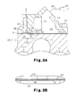
line 2B of Fig. 2A; - Fig. 3A is a cross-sectional view of Fig. 1 taken along the
line 3A-3A; - Fig. 3B is an enlarged view of the part encircled by the
line 3B of Fig. 3A; - Fig. 4 is a cross-sectional view of Fig. 2A taken along the line 4-4;
- Fig. 5 is a cross-sectional view of Fig. 2A taken along the line 5-5;
- Fig. 6 is a cross-sectional view of Fig. 2A taken along the line 6-6 and
- Fig. 7 is a partial cross-sectional side view of a second embodiment of a structure for sensing flow rate of refrigerant.
- A first embodiment of a structure for sensing flow rate of refrigerant according to the present invention is described with reference to Figs. 1 to 6.
- As shown in Fig. 1, a
front housing member 12 is secured to the front end of acylinder block 11. Arear housing member 13 is secured to the rear end of thecylinder block 11 with avalve plate 14,valve flap plates retainer plate 17 arranged in between. Thecylinder block 11, thefront housing member 12, and therear housing member 13 form a housing of avariable displacement compressor 10. - The
cylinder block 11 and thefront housing member 12 define acontrol pressure chamber 121. Thefront housing member 12 and thecylinder block 11 rotatably support arotary shaft 18 withradial bearings rotary shaft 18 projects from thecontrol pressure chamber 121 to the outside, and receives power from a vehicle engine E, which is an external power source. - A
rotary support 21 is fixed to therotary shaft 18, and aswash plate 22 is supported on therotary shaft 18. Theswash plate 22 is permitted to incline with respect to and slide along an axial direction of therotary shaft 18. A pair of guide holes 211 are formed in therotary support 21, and a pair of guide pins 23 are formed on theswash plate 22. The guide pins 23 are slidably fitted in the guide holes 211. The engagement of the guide pins 23 with the guide holes 211 allows theswash plate 22 to be tiltable with respect to the axial direction of therotary shaft 18 and rotatable together with therotary shaft 18. The guide holes 211 slidably guide the guide pins 23, and therotary shaft 18 slidably supports theswash plate 22. These actions permit theswash plate 22 to be inclined. - When the center of the
swash plate 22 moves toward therotary support 21, the inclination of theswash plate 22 increases. When contacting theswash plate 22, therotary support 21 determines the maximum inclination of theswash plate 22. When in a position indicated by solid line in Fig. 1, theswash plate 22 is at the maximum inclination position. When in a position indicated by chain line, theswash plate 22 is at the minimum inclination position. - A plurality of cylinder bores 111 extend through the
cylinder block 11. Each cylinder bore 111 accommodates apiston 24. The rotation of theswash plate 22 is converted to reciprocation of thepistons 24 by means ofshoes 25. Thus, eachpiston 24 reciprocates in the corresponding cylinder bore 111. - A
suction chamber 131 and adischarge chamber 132 are defined in therear housing member 13. Thesuction chamber 131 forms a suction pressure zone and thedischarge chamber 132 forms a discharge pressure zone.Suction ports 141 are formed in avalve plate 14, avalve flap plate 16, and aretainer plate 17. Discharge ports 142 are formed in thevalve plate 14 and avalve flap plate 15. Suction valve flaps 151 are formed on thevalve flap plate 15, and discharge valve flaps 161 are formed on thevalve flap plate 16. As eachpiston 24 moves from the top dead center to the bottom dead center (from the right side to the left side in Fig. 1), refrigerant in thesuction chamber 131 is drawn into the associated cylinder bore 111 through the correspondingsuction port 141 while flexing thesuction valve flap 151. When eachpiston 24 moves from the bottom dead center to the top dead center (from the left side to the right side in Fig. 1), gaseous refrigerant in the corresponding cylinder bore 111 is discharged into thedischarge chamber 132, which is a discharge pressure zone, through the corresponding discharge port 142 while flexing thedischarge valve flap 161. Theretainer plate 17 includesretainers 171, which correspond to thedischarge valves 161. Eachretainer 171 restricts the opening degree of the correspondingdischarge valve flap 161. - An electromagnetic
displacement control valve 26 is installed in therear housing member 13. Thedisplacement control valve 26 is positioned in asupply passage 27 that connects thedischarge chamber 132 to thecontrol pressure chamber 121. The opening degree of thevalve 26 is adjusted by a pressure in thesuction chamber 131 and a duty ratio when an electromagnetic solenoid (not shown) of thevalve 26 is powered. When a valve hole of thevalve 26 is closed, refrigerant in thedischarge chamber 132 is not sent to thecontrol pressure chamber 121. - The
control pressure chamber 121 communicates with thesuction chamber 131 through a bleed passage 28 and refrigerant in thecontrol pressure chamber 121 flows out to thesuction chamber 131 through bleed passage 28. When the valve opening of thedisplacement control valve 26 becomes greater, the greater amount of refrigerant flows from the discharge chamber132 through thesupply passage 27 to thecontrol pressure chamber 121, which increases pressure in thecontrol pressure chamber 121. As a result, the inclination of theswash plate 22 and thus displacement of thecompressor 10 are decreased. When the valve opening of thedisplacement control valve 26 becomes smaller, the smaller amount of refrigerant flow from thedischarge chamber 132 through thesupply passage 27 to thecontrol pressure chamber 121, which decreases a pressure in thecontrol pressure chamber 121. As a result, the inclination of theswash plate 22 and thus displacement of thecompressor 10 are increased. - A
base 29 is integrally formed with thecylinder block 11, which is a part of an entire housing of the compressor, to protrude from the outercircumferential surface 110 of thecylinder block 11. As illustrated in Fig. 2A, anupper end 291 of thebase 29, or an outer surface of thecylinder block 11 is flat. Amuffler forming member 30 which serves as a passage forming member is attached to theupper end 291 with a sealinggasket 31. As illustrated in Fig. 2B, thegasket 31, serving as a partition plate, is formed by attachingrubber layers core metal plate 311 by heating. Thegasket 31 prevents leakage of refrigerant from between the base 29 and themuffler forming member 30. As illustrated in Fig. 3A, themuffler forming member 30 and thegasket 31 are secured together with ascrew 32. - As illustrated in Fig. 1 the
muffler forming member 30 includes amuffler chamber 33 and apressure introduction chamber 34. Thepressure introduction chamber 34 accommodates a movingbody 35. The movingbody 35 divides thepressure introduction chamber 34 into afirst pressure chamber 341 and asecond pressure chamber 342. Acompression spring 37 is positioned between the movingbody 35 and avalve seat 36 in the form of ring. Thecompression spring 37 urges the movingbody 35 from thesecond pressure chamber 342 toward thefirst pressure chamber 341. Thesecond pressure chamber 342 communicates with themuffler chamber 33 through a center hole in thevalve seat 36. - A
permanent magnet 351 is attached to the movingbody 35 and amagnetic detector 46 is provided on an outer surface of themuffler forming member 30. Themagnetic detector 46 detects magnetic flux density of thepermanent magnet 351. The magnetic flux density detected by themagnetic detector 46 is sent to a displacement control computer C1. - An
upstream passage 39 is formed invalve plate 14 andcylinder block 11 to connect with thedischarge chamber 132. Arestriction hole 38 is formed in thegasket 31 to penetrate thegasket 31 in the thickness direction of thegasket 31 so that theupstream passage 39 and themuffler chamber 33 are connected. Fig. 4 illustrates theupstream passage 39 formed in thecylinder block 11 and Fig. 5 illustrates therestriction hole 38 extending through thegasket 31. - As illustrated in Fig. 2A, the
muffler chamber 33 is connected to thedischarge chamber 132 through therestriction hole 38 and theupstream passage 39. Apressure introduction passage 40 extends in themuffler forming member 30 and penetrate thegasket 31. Thefirst pressure chamber 341 communicates with theupstream passage 39 via thepressure introduction passage 40. - As illustrated in Figs. 3A and 3B, an
opening 41, which is a part of thepressure introduction passage 40, extends through thegasket 31 in the thickness direction of thegasket 31. The flow passage area of theopening 41 is smaller than that of thepressure introduction passage 40 in themuffler forming member 30. - Refrigerant in the
discharge chamber 132 flows through theupstream passage 39, therestriction hole 38, and themuffler chamber 33 to the externalrefrigerant circuit 42. Theupstream passage 39, therestriction hole 38, and themuffler chamber 33 form a refrigerant passage 50 (as shown in Fig. 2A) of refrigerant that is discharged from inside the housing of thecompressor 10 to outside the housing. Therestriction hole 38 divides therefrigerant passage 50 into theupstream passage 39 and themuffler chamber 33 that is a downstream passage. - As illustrated in Fig.1, refrigerant flowing out of the external
refrigerant circuit 42 is returned to thesuction chamber 131. Aheat exchanger 43 for conducting heat away from refrigerant, anexpansion valve 44, and aheat exchanger 45 for transferring ambient heat to refrigerant are positioned in the externalrefrigerant circuit 42. A thermal sensor for sensing temperature of refrigerant is positioned at the exit of theheat exchanger 45. Theexpansion valve 44 controls the flow rate of refrigerant depending on the change in temperature of the refrigerant. - The
restriction hole 38 restricts the flow of the refrigerant that flows from theupstream passage 39 through therestriction hole 38 to themuffler chamber 33. This results in a pressure difference between a pressure in theupstream passage 39 and a pressure in themuffler chamber 33. The pressure in themuffler chamber 33 is lower than the pressure in theupstream passage 39. - As illustrated in Fig.2A, pressure in the
upstream passage 39 extends to thefirst pressure chamber 341 through thepressure introduction passage 40 and a pressure in themuffler chamber 33 extends to thesecond pressure chamber 342 through the central hole of thevalve seat 36. A pressure in thefirst pressure chamber 341 and a pressure in thesecond pressure chamber 342 counteract via the movingbody 35. A differential pressure between the pressure in the first pressure chamber 341 (or the pressure in the upstream passage 39) and the pressure in the second pressure chamber 342 (or the pressure in the muffler chamber 33) acts against a spring force by thecompression spring 37 so that the movingbody 35 is placed in a position at which the differential pressure and the spring force are balanced. - When the flow rate of refrigerant that flows through the
upstream passage 39, therestriction hole 38, and themuffler chamber 33 is increased, the differential pressure becomes greater. Thus, the movingbody 35 moves in a direction from thefirst pressure chamber 341 to thesecond pressure chamber 342. When the flow rate of refrigerant that flows through theupstream passage 39, therestriction hole 38, and themuffler chamber 33 is decreased, the differential pressure becomes smaller. Thus, the movingbody 35 moves in a direction from thesecond pressure chamber 342 to thefirst pressure chamber 341. The magnetic flux density detected by themagnetic detector 46 reflect the location of the movingbody 35, and thus, the flow rate of discharged refrigerant that flows through theupstream passage 39, therestriction hole 38, and themuffler chamber 33. - The
pressure introduction chamber 34, the movingbody 35, thecompression spring 37, and themagnetic detector 46 form the differential pressure-typeflow rate sensor 49. Fig.2A that picks up a pressure in theupstream passage 39 and a pressure in themuffler chamber 33 serving as a downstream passage to detect the flow rate of refrigerant in therefrigerant passage 50. Thepressure introduction passage 40 in themuffler forming member 30 has a linear shape and extends from asurface 301 ofmuffler forming member 30 facing to the base 29 (or the cylinder block 11) to thesensor 49, as shown in Figs.2A and 3A. - As illustrated in Fig. 1, the displacement control computer C is connected to a compartment
temperature setting device 47 and acompartment temperature detector 48. The displacement control computer C1 controls the current supplied to the electromagnetic solenoid so that the temperature detected by thecompartment temperature detector 48 is converged to a target temperature set by the compartmenttemperature setting device 47 based on the information on the magnetic flux density obtained from themagnetic detector 46. In other words, the displacement control computer C1 feedback-controls the flow rate of discharged refrigerant to an appropriate flow rate based on the information on the magnetic flux density obtained from themagnetic detector 46. - The displacement control computer C1 transmits the torque data of the
compressor 10 that are measured based on the information on the magnetic flux density to a engine control computer C2. The engine control computer C2, based on the torque data, controls the speed of the engine to an appropriate value. - The present embodiment has the following advantages.
- The
restriction hole 38 is provided in theplanar gasket 31 to extend through thegasket 31. This facilitates formation of therestriction hole 38 by pressing. Thus, therestriction hole 38 that has a desired size corresponding to the flow passage area can be formed with high accuracy. If agasket 31 having a thickness that corresponds to a desired length of therestriction hole 38 is used, theresultant hole 38 should have the desired length. In this regard, therestriction hole 38 may also be formed with high accuracy. - The smaller the flow passage area of the
pressure introduction passage 40 for introducing pressure into theupstream passage 39 to thefirst pressure chamber 341, the less the effect that hydrodynamic pressure from the discharged refrigerant flowing in theupstream passage 39 will have on theflow rate sensor 49. The configuration that theopening 41, which is a part of thepressure introduction passage 40, is provided in thegasket 31 is advantageous in making the flow passage area of theopening 41 small. - If the pressure introduction passage is formed by forming a space in a structure by die molding and then forming a pressure introduction passage by extending the passage from the space with a drill, the volume of the
muffler chamber 33 will be limited by the space. Meanwhile, when the pressure introduction passage40 is formed in themuffler forming member 30 in the form of a straight passage, thepressure introduction passage 40 may be readily formed by drilling themuffler forming member 30 from the bottom side and no such space is required. Therefore, the volume of themuffler chamber 33 may be made greater. - The
gasket 31 is suitable for easily providing therestriction hole 38 and theopening 41. - Pressure in the
muffler chamber 33 is introduced into thesecond pressure chamber 342, which is open to themuffler chamber 33. The structure that connects themuffler chamber 33 with thesecond pressure chamber 342 is simple. The fact that themuffler chamber 33 is a downstream passage of therefrigerant passage 50 facilitates introduction of the pressure in the downstream passage to thesensor 49. - The gasket includes a
metal plate 311 as a core member. This is advantageous in improving accuracy of pressing the hole. - Referring to Fig.7, a second embodiment is described. In the second embodiment, like reference numerals refer to like elements.
- In the second embodiment, the
muffler chamber 51 is recessed in the base 29 (or cylinder block 11) so as to communicate with themuffler chamber 33. Themuffler chamber 51 is a part of the downstream passage and contributes to improvement in noise reduction by increasing the volume of theentire muffler chamber 51. - The invention may be embodied in the following forms.
- The passage forming member may be provided between the external
refrigerant circuit 42 and thesuction chamber 131. In such a case, a differential pressure-typeflow rate sensor 49 in the passage forming member senses the flow rate of refrigerant that flows from the externalrefrigerant circuit 42 into thesuction chamber 131. - The
first pressure chamber 341 and thesecond pressure chamber 342 in thesensor 49 may be interchanged. - The moving
body 35 in thesensor 49 may be a bellows or a diaphragm. - A seal ring may be placed between the base 29 and the
muffler forming member 30 to seal around therestriction hole 38 of the partition plate. - A seal ring may be placed between the base 29 and the
muffler forming member 30 to seal around theopening 41 of the partition plate. - The
muffler forming member 30 may be attached to the outer circumferential surface of thefront housing 12 or that of therear housing 13 instead of the outer circumferential surface of thecylinder block 11. Alternatively, themuffler forming member 30 may be attached to two or more of thecylinder block 11, thefront housing 12, and therear housing 13. - The
gasket 31 may be formed by attaching resin layers to both sides of themetal plate 311. - The present examples and embodiments are to be considered as illustrative and not restrictive and the invention is not to be limited to the details given herein, but may be modified within the scope and equivalence of the appended claims.
- A structure for sensing refrigerant flow rate in a compressor (10). The structure includes a passage forming member, a restriction hole (38), a differential pressure-type flow rate sensor (49), and a partition plate. The compressor (10) includes a housing connected to an external refrigerant circuit (42) via a refrigerant passage (50). The passage forming member is connected to an outer surface of the housing and forms a part of the refrigerant passage (50). The restriction hole (38) divides the refrigerant passage (50) into an upstream passage (39) and a downstream passage. The sensor (49) is provided in the passage forming member and picks up a pressure in the upstream passage (39) and a pressure in the downstream passage to sense flow rate of refrigerant in the refrigerant passage (50). The upstream passage (39) is formed in either the housing or the passage forming member. The structure further comprises a partition plate disposed between the housing and the passage forming member. The restriction hole (38) is formed in the partition plate to extend through the partition plate.
Claims (8)
- A structure for sensing refrigerant flow rate in a compressor (10), the compressor (10) including a housing connected to an external refrigerant circuit (42) via a refrigerant passage (50), the structure comprising:a passage forming member connected to an outer surface of the housing, wherein the passage forming member forms a part of the refrigerant passage (50);a restriction hole (38) for dividing the refrigerant passage (50) into an upstream passage (39) and a downstream passage;a differential pressure-type flow rate sensor (49) provided in the passage forming member, wherein the sensor (49) picks up a pressure in the upstream passage (39) and a pressure in the downstream passage to sense flow rate of refrigerant in the refrigerant passage (50); characterized in that the upstream passage (39) is formed in either the housing or the passage forming member, wherein the structure further comprises a partition plate disposed between the housing and the passage forming member,wherein the restriction hole (38) is formed in the partition plate to extend through the partition plate.
- The structure according to claim 1 characterized in that the passage forming member forms a part of the refrigerant passage (50) of the refrigerant that is discharged from inside the housing to the outside of the housing, wherein the upstream passage (39) is formed in the housing and the downstream passage is formed in the passage forming member.
- The structure according to claim 2 characterized in that the structure further comprising a pressure introduction passage (40) for introducing the pressure in the upstream passage (39) into the sensor (49), wherein the pressure introduction passage (40) is formed to extend through the partition plate.
- The structure according to claim 3 characterized in that the pressure introduction passage (40) is a linear passage extending from the sensor (49) to the partition plate.
- The structure according to any one of claims 2 to 4 characterized in that the downstream passage comprises a muffler chamber (33).
- The structure according to any one of claims 2 to 5 characterized in that the partition plate comprises a gasket (31).
- The structure according to any one of claims 1 to 6 characterized in that the compressor (10) is a variable displacement compressor (10) for controlling displacement by adjusting a pressure in a control pressure chamber (121),
wherein the refrigerant circuit includes a discharge pressure zone and a suction pressure zone, wherein the compressor (10) includes a supply passage (27) for connecting the control pressure chamber (121) to the discharge pressure zone and a bleed passage (29) for connecting the suction pressure zone to the control pressure chamber (121), wherein the pressure in the control pressure chamber (121) is adjusted by supplying refrigerant in discharge pressure zone to the control pressure chamber (121) via the supply passage (27) and releasing refrigerant in the control pressure chamber (121) into the suction pressure zone via the bleed passage (29). - The structure according to any one of claims 3 to 7 characterized in that the sensor (49) includes:a pressure introduction chamber (34) formed in the passage forming member;a moving body (35) for dividing the pressure introduction chamber (34) into a first pressure chamber (3419 and a second pressure chamber (342), wherein the moving body (35) includes a permanent magnet (351),wherein the first pressure chamber (341) is connected to the upstream passage (39) through the pressure introduction passage (40) and the second pressure chamber (342) is connected to the downstream passage;
a compression spring (37) for urging the moving body (35) from the second pressure chamber (342) to first pressure chamber (341); and
a magnetic detector (46) for detecting magnetic flux density of the permanent magnet (351), wherein the detector (46) is disposed outside the passage forming member, wherein the magnetic flux density reflects a location of the moving body (35) determined by the differential pressure.
Applications Claiming Priority (1)
| Application Number | Priority Date | Filing Date | Title |
|---|---|---|---|
| JP2006224204A JP2008045522A (en) | 2006-08-21 | 2006-08-21 | Refrigerant flow rate detecting structure in compressor |
Publications (2)
| Publication Number | Publication Date |
|---|---|
| EP1895163A1 true EP1895163A1 (en) | 2008-03-05 |
| EP1895163B1 EP1895163B1 (en) | 2011-01-05 |
Family
ID=38814349
Family Applications (1)
| Application Number | Title | Priority Date | Filing Date |
|---|---|---|---|
| EP07114595A Not-in-force EP1895163B1 (en) | 2006-08-21 | 2007-08-20 | Structure for sensing refrigerant flow rate in a compressor |
Country Status (5)
| Country | Link |
|---|---|
| US (1) | US8186172B2 (en) |
| EP (1) | EP1895163B1 (en) |
| JP (1) | JP2008045522A (en) |
| AT (1) | ATE494479T1 (en) |
| DE (1) | DE602007011699D1 (en) |
Families Citing this family (3)
| Publication number | Priority date | Publication date | Assignee | Title |
|---|---|---|---|---|
| JP4930444B2 (en) * | 2008-04-11 | 2012-05-16 | 株式会社豊田自動織機 | Variable capacity compressor |
| JP6101892B2 (en) | 2013-04-24 | 2017-03-29 | 株式会社テージーケー | Variable displacement compressor and flow sensor mounting structure |
| JP2023174096A (en) * | 2022-05-27 | 2023-12-07 | キャタピラー エス エー アール エル | Control calibration device of variable displacement pump and method thereof |
Citations (5)
| Publication number | Priority date | Publication date | Assignee | Title |
|---|---|---|---|---|
| EP0219489A1 (en) | 1985-10-15 | 1987-04-22 | AVL Gesellschaft für Verbrennungskraftmaschinen und Messtechnik mbH.Prof.Dr.Dr.h.c. Hans List | Measuring orifice for a measuring arrangement for measuring fluid flow and measuring arrangement using such a measuring orifice |
| JPH04353210A (en) * | 1991-05-31 | 1992-12-08 | Kyocera Corp | Regeneration of particulate trap filter |
| EP0992684A2 (en) * | 1998-10-08 | 2000-04-12 | TGK Co., Ltd. | Solenoid controlled valve and variable displacement compressor |
| JP2004012394A (en) | 2002-06-10 | 2004-01-15 | Komatsu Ltd | Flow sensor |
| EP1431578A2 (en) | 2002-12-19 | 2004-06-23 | Kabushiki Kaisha Toyota Jidoshokki | Control system for a variable displacement compressor |
Family Cites Families (16)
| Publication number | Priority date | Publication date | Assignee | Title |
|---|---|---|---|---|
| DD219489A1 (en) | 1983-10-31 | 1985-03-06 | Adw Ddr | PROCESS FOR THE PREPARATION OF CARDA-16,20 (22) -DIIENOLIDES AND CARDA-16,20 (22) -DIOLIDE GLYCOSIDES |
| JPS60209116A (en) | 1984-03-31 | 1985-10-21 | Keihin Seiki Mfg Co Ltd | Flow meter |
| US4646624A (en) * | 1984-08-06 | 1987-03-03 | United Technologies Corporation | Differential pressure sensor |
| JPH0626484B2 (en) | 1987-01-16 | 1994-04-13 | 三菱農機株式会社 | Lowering device for working unit in paddy working machine |
| JPH01253574A (en) * | 1988-04-01 | 1989-10-09 | Toyota Autom Loom Works Ltd | Variable-volume swash plate type compressor |
| US5284053A (en) * | 1992-01-10 | 1994-02-08 | The Boc Group, Inc. | Controlled flow volumetric flowmeter |
| JP2000205666A (en) * | 1999-01-12 | 2000-07-28 | Toyota Autom Loom Works Ltd | Air conditioner |
| JP3932728B2 (en) * | 1999-08-09 | 2007-06-20 | 株式会社豊田自動織機 | Control unit for variable capacity compressor |
| JP3942851B2 (en) * | 2001-07-31 | 2007-07-11 | 株式会社テージーケー | Capacity control valve |
| JP2004034943A (en) * | 2002-07-08 | 2004-02-05 | Tgk Co Ltd | Control method for refrigeration cycle |
| JP2006057506A (en) * | 2004-08-19 | 2006-03-02 | Tgk Co Ltd | Control valve for variable displacement compressor |
| JP2006177300A (en) * | 2004-12-24 | 2006-07-06 | Toyota Industries Corp | Capacity control mechanism in variable displacement compressor |
| JP4353210B2 (en) | 2006-07-10 | 2009-10-28 | トヨタ自動車株式会社 | Control device for internal combustion engine |
| JP2008045523A (en) * | 2006-08-21 | 2008-02-28 | Toyota Industries Corp | Capacity control structure in variable displacement compressor |
| JP2008107282A (en) * | 2006-10-27 | 2008-05-08 | Toyota Industries Corp | Refrigerant flow rate detection structure in compressor |
| JP2008121636A (en) * | 2006-11-15 | 2008-05-29 | Toyota Industries Corp | Refrigerant flow volume detecting structure in compressor |
-
2006
- 2006-08-21 JP JP2006224204A patent/JP2008045522A/en active Pending
-
2007
- 2007-08-20 AT AT07114595T patent/ATE494479T1/en not_active IP Right Cessation
- 2007-08-20 EP EP07114595A patent/EP1895163B1/en not_active Not-in-force
- 2007-08-20 DE DE602007011699T patent/DE602007011699D1/en active Active
- 2007-08-20 US US11/894,320 patent/US8186172B2/en not_active Expired - Fee Related
Patent Citations (6)
| Publication number | Priority date | Publication date | Assignee | Title |
|---|---|---|---|---|
| EP0219489A1 (en) | 1985-10-15 | 1987-04-22 | AVL Gesellschaft für Verbrennungskraftmaschinen und Messtechnik mbH.Prof.Dr.Dr.h.c. Hans List | Measuring orifice for a measuring arrangement for measuring fluid flow and measuring arrangement using such a measuring orifice |
| JPH04353210A (en) * | 1991-05-31 | 1992-12-08 | Kyocera Corp | Regeneration of particulate trap filter |
| EP0992684A2 (en) * | 1998-10-08 | 2000-04-12 | TGK Co., Ltd. | Solenoid controlled valve and variable displacement compressor |
| JP2004012394A (en) | 2002-06-10 | 2004-01-15 | Komatsu Ltd | Flow sensor |
| EP1431578A2 (en) | 2002-12-19 | 2004-06-23 | Kabushiki Kaisha Toyota Jidoshokki | Control system for a variable displacement compressor |
| JP2004197679A (en) | 2002-12-19 | 2004-07-15 | Toyota Industries Corp | Control device for variable displacement compressor |
Also Published As
| Publication number | Publication date |
|---|---|
| ATE494479T1 (en) | 2011-01-15 |
| US8186172B2 (en) | 2012-05-29 |
| DE602007011699D1 (en) | 2011-02-17 |
| US20080041080A1 (en) | 2008-02-21 |
| JP2008045522A (en) | 2008-02-28 |
| EP1895163B1 (en) | 2011-01-05 |
Similar Documents
| Publication | Publication Date | Title |
|---|---|---|
| US7841839B2 (en) | Displacement control structure for a variable displacement compressor | |
| JP5235569B2 (en) | Capacity control valve, variable capacity compressor and capacity control system of variable capacity compressor | |
| US20050287014A1 (en) | Displacement control valve for variable displacement compressor | |
| WO2009116485A1 (en) | Displacement control valve for variable displacement compressor, and reciprocating type variable displacement compressor | |
| US6585494B1 (en) | Variable-capacity control for refrigerating cycle without using a large pressure control valve | |
| JP5765566B2 (en) | VEHICLE AIR CONDITIONER AND METHOD FOR DETERMINING OPERATION STATE OF VARIABLE DISPLACEMENT COMPRESSOR IN VEHICLE AIR CONDITIONER | |
| CN100591916C (en) | Method and system for controlling a variable displacement compressor | |
| JP3726759B2 (en) | Control device for variable capacity compressor | |
| US20070264131A1 (en) | Variable displacement compressor | |
| US7493829B2 (en) | Flow meter for variable displacement compressor | |
| US8186172B2 (en) | Structure for sensing refrigerant flow rate in a compressor | |
| EP1925821A2 (en) | Structure for sensing refrigerant flow rate in a compressor | |
| CN101809288B (en) | Displacement control system for variable displacement compressor | |
| EP1936191A2 (en) | Variable displacement compressor | |
| JP5413956B2 (en) | Driving torque calculation device for variable capacity compressor and air conditioning system for vehicle | |
| JP2017133393A (en) | Variable displacement swash plate compressor | |
| JP2007211701A (en) | Flow rate detection device in variable displacement compressor | |
| KR101766509B1 (en) | Variable displacement swash plate type compressor | |
| CN101815866B (en) | Variable displacement compressor | |
| KR102797366B1 (en) | Variable capacity swash plate compressor | |
| JP5474284B2 (en) | Capacity control system for variable capacity compressor | |
| JP5260906B2 (en) | Volume control valve for variable capacity compressor | |
| KR20140100825A (en) | Variable displacement swash plate type compressor | |
| JP2007315189A (en) | Capacity control valve of variable displacement compressor | |
| JP2016169698A (en) | Variable capacity type swash plate compressor |
Legal Events
| Date | Code | Title | Description |
|---|---|---|---|
| PUAI | Public reference made under article 153(3) epc to a published international application that has entered the european phase |
Free format text: ORIGINAL CODE: 0009012 |
|
| 17P | Request for examination filed |
Effective date: 20070820 |
|
| AK | Designated contracting states |
Kind code of ref document: A1 Designated state(s): AT BE BG CH CY CZ DE DK EE ES FI FR GB GR HU IE IS IT LI LT LU LV MC MT NL PL PT RO SE SI SK TR |
|
| AX | Request for extension of the european patent |
Extension state: AL BA HR MK YU |
|
| AKX | Designation fees paid |
Designated state(s): AT BE BG CH CY CZ DE DK EE ES FI FR GB GR HU IE IS IT LI LT LU LV MC MT NL PL PT RO SE SI SK TR |
|
| GRAP | Despatch of communication of intention to grant a patent |
Free format text: ORIGINAL CODE: EPIDOSNIGR1 |
|
| GRAS | Grant fee paid |
Free format text: ORIGINAL CODE: EPIDOSNIGR3 |
|
| GRAA | (expected) grant |
Free format text: ORIGINAL CODE: 0009210 |
|
| AK | Designated contracting states |
Kind code of ref document: B1 Designated state(s): AT BE BG CH CY CZ DE DK EE ES FI FR GB GR HU IE IS IT LI LT LU LV MC MT NL PL PT RO SE SI SK TR |
|
| REG | Reference to a national code |
Ref country code: GB Ref legal event code: FG4D |
|
| REG | Reference to a national code |
Ref country code: CH Ref legal event code: EP |
|
| REG | Reference to a national code |
Ref country code: IE Ref legal event code: FG4D |
|
| REF | Corresponds to: |
Ref document number: 602007011699 Country of ref document: DE Date of ref document: 20110217 Kind code of ref document: P |
|
| REG | Reference to a national code |
Ref country code: DE Ref legal event code: R096 Ref document number: 602007011699 Country of ref document: DE Effective date: 20110217 |
|
| REG | Reference to a national code |
Ref country code: NL Ref legal event code: VDEP Effective date: 20110105 |
|
| PG25 | Lapsed in a contracting state [announced via postgrant information from national office to epo] |
Ref country code: SI Free format text: LAPSE BECAUSE OF FAILURE TO SUBMIT A TRANSLATION OF THE DESCRIPTION OR TO PAY THE FEE WITHIN THE PRESCRIBED TIME-LIMIT Effective date: 20110105 |
|
| LTIE | Lt: invalidation of european patent or patent extension |
Effective date: 20110105 |
|
| PG25 | Lapsed in a contracting state [announced via postgrant information from national office to epo] |
Ref country code: ES Free format text: LAPSE BECAUSE OF FAILURE TO SUBMIT A TRANSLATION OF THE DESCRIPTION OR TO PAY THE FEE WITHIN THE PRESCRIBED TIME-LIMIT Effective date: 20110416 Ref country code: LT Free format text: LAPSE BECAUSE OF FAILURE TO SUBMIT A TRANSLATION OF THE DESCRIPTION OR TO PAY THE FEE WITHIN THE PRESCRIBED TIME-LIMIT Effective date: 20110105 Ref country code: SE Free format text: LAPSE BECAUSE OF FAILURE TO SUBMIT A TRANSLATION OF THE DESCRIPTION OR TO PAY THE FEE WITHIN THE PRESCRIBED TIME-LIMIT Effective date: 20110105 Ref country code: LV Free format text: LAPSE BECAUSE OF FAILURE TO SUBMIT A TRANSLATION OF THE DESCRIPTION OR TO PAY THE FEE WITHIN THE PRESCRIBED TIME-LIMIT Effective date: 20110105 Ref country code: PT Free format text: LAPSE BECAUSE OF FAILURE TO SUBMIT A TRANSLATION OF THE DESCRIPTION OR TO PAY THE FEE WITHIN THE PRESCRIBED TIME-LIMIT Effective date: 20110505 Ref country code: IS Free format text: LAPSE BECAUSE OF FAILURE TO SUBMIT A TRANSLATION OF THE DESCRIPTION OR TO PAY THE FEE WITHIN THE PRESCRIBED TIME-LIMIT Effective date: 20110505 Ref country code: GR Free format text: LAPSE BECAUSE OF FAILURE TO SUBMIT A TRANSLATION OF THE DESCRIPTION OR TO PAY THE FEE WITHIN THE PRESCRIBED TIME-LIMIT Effective date: 20110406 |
|
| PG25 | Lapsed in a contracting state [announced via postgrant information from national office to epo] |
Ref country code: PL Free format text: LAPSE BECAUSE OF FAILURE TO SUBMIT A TRANSLATION OF THE DESCRIPTION OR TO PAY THE FEE WITHIN THE PRESCRIBED TIME-LIMIT Effective date: 20110105 Ref country code: FI Free format text: LAPSE BECAUSE OF FAILURE TO SUBMIT A TRANSLATION OF THE DESCRIPTION OR TO PAY THE FEE WITHIN THE PRESCRIBED TIME-LIMIT Effective date: 20110105 Ref country code: NL Free format text: LAPSE BECAUSE OF FAILURE TO SUBMIT A TRANSLATION OF THE DESCRIPTION OR TO PAY THE FEE WITHIN THE PRESCRIBED TIME-LIMIT Effective date: 20110105 Ref country code: BG Free format text: LAPSE BECAUSE OF FAILURE TO SUBMIT A TRANSLATION OF THE DESCRIPTION OR TO PAY THE FEE WITHIN THE PRESCRIBED TIME-LIMIT Effective date: 20110405 Ref country code: CY Free format text: LAPSE BECAUSE OF FAILURE TO SUBMIT A TRANSLATION OF THE DESCRIPTION OR TO PAY THE FEE WITHIN THE PRESCRIBED TIME-LIMIT Effective date: 20110105 Ref country code: BE Free format text: LAPSE BECAUSE OF FAILURE TO SUBMIT A TRANSLATION OF THE DESCRIPTION OR TO PAY THE FEE WITHIN THE PRESCRIBED TIME-LIMIT Effective date: 20110105 Ref country code: AT Free format text: LAPSE BECAUSE OF FAILURE TO SUBMIT A TRANSLATION OF THE DESCRIPTION OR TO PAY THE FEE WITHIN THE PRESCRIBED TIME-LIMIT Effective date: 20110105 |
|
| PG25 | Lapsed in a contracting state [announced via postgrant information from national office to epo] |
Ref country code: EE Free format text: LAPSE BECAUSE OF FAILURE TO SUBMIT A TRANSLATION OF THE DESCRIPTION OR TO PAY THE FEE WITHIN THE PRESCRIBED TIME-LIMIT Effective date: 20110105 Ref country code: DK Free format text: LAPSE BECAUSE OF FAILURE TO SUBMIT A TRANSLATION OF THE DESCRIPTION OR TO PAY THE FEE WITHIN THE PRESCRIBED TIME-LIMIT Effective date: 20110105 |
|
| PLBE | No opposition filed within time limit |
Free format text: ORIGINAL CODE: 0009261 |
|
| STAA | Information on the status of an ep patent application or granted ep patent |
Free format text: STATUS: NO OPPOSITION FILED WITHIN TIME LIMIT |
|
| PG25 | Lapsed in a contracting state [announced via postgrant information from national office to epo] |
Ref country code: SK Free format text: LAPSE BECAUSE OF FAILURE TO SUBMIT A TRANSLATION OF THE DESCRIPTION OR TO PAY THE FEE WITHIN THE PRESCRIBED TIME-LIMIT Effective date: 20110105 Ref country code: CZ Free format text: LAPSE BECAUSE OF FAILURE TO SUBMIT A TRANSLATION OF THE DESCRIPTION OR TO PAY THE FEE WITHIN THE PRESCRIBED TIME-LIMIT Effective date: 20110105 Ref country code: RO Free format text: LAPSE BECAUSE OF FAILURE TO SUBMIT A TRANSLATION OF THE DESCRIPTION OR TO PAY THE FEE WITHIN THE PRESCRIBED TIME-LIMIT Effective date: 20110105 |
|
| PGFP | Annual fee paid to national office [announced via postgrant information from national office to epo] |
Ref country code: DE Payment date: 20110817 Year of fee payment: 5 |
|
| 26N | No opposition filed |
Effective date: 20111006 |
|
| PG25 | Lapsed in a contracting state [announced via postgrant information from national office to epo] |
Ref country code: MT Free format text: LAPSE BECAUSE OF FAILURE TO SUBMIT A TRANSLATION OF THE DESCRIPTION OR TO PAY THE FEE WITHIN THE PRESCRIBED TIME-LIMIT Effective date: 20110105 Ref country code: IT Free format text: LAPSE BECAUSE OF FAILURE TO SUBMIT A TRANSLATION OF THE DESCRIPTION OR TO PAY THE FEE WITHIN THE PRESCRIBED TIME-LIMIT Effective date: 20110105 |
|
| REG | Reference to a national code |
Ref country code: DE Ref legal event code: R097 Ref document number: 602007011699 Country of ref document: DE Effective date: 20111006 |
|
| PG25 | Lapsed in a contracting state [announced via postgrant information from national office to epo] |
Ref country code: MC Free format text: LAPSE BECAUSE OF NON-PAYMENT OF DUE FEES Effective date: 20110831 |
|
| REG | Reference to a national code |
Ref country code: CH Ref legal event code: PL |
|
| GBPC | Gb: european patent ceased through non-payment of renewal fee |
Effective date: 20110820 |
|
| PG25 | Lapsed in a contracting state [announced via postgrant information from national office to epo] |
Ref country code: CH Free format text: LAPSE BECAUSE OF NON-PAYMENT OF DUE FEES Effective date: 20110831 Ref country code: LI Free format text: LAPSE BECAUSE OF NON-PAYMENT OF DUE FEES Effective date: 20110831 |
|
| REG | Reference to a national code |
Ref country code: FR Ref legal event code: ST Effective date: 20120430 |
|
| REG | Reference to a national code |
Ref country code: IE Ref legal event code: MM4A |
|
| PG25 | Lapsed in a contracting state [announced via postgrant information from national office to epo] |
Ref country code: IE Free format text: LAPSE BECAUSE OF NON-PAYMENT OF DUE FEES Effective date: 20110820 |
|
| PG25 | Lapsed in a contracting state [announced via postgrant information from national office to epo] |
Ref country code: GB Free format text: LAPSE BECAUSE OF NON-PAYMENT OF DUE FEES Effective date: 20110820 Ref country code: FR Free format text: LAPSE BECAUSE OF NON-PAYMENT OF DUE FEES Effective date: 20110831 |
|
| PG25 | Lapsed in a contracting state [announced via postgrant information from national office to epo] |
Ref country code: LU Free format text: LAPSE BECAUSE OF NON-PAYMENT OF DUE FEES Effective date: 20110820 |
|
| PG25 | Lapsed in a contracting state [announced via postgrant information from national office to epo] |
Ref country code: DE Free format text: LAPSE BECAUSE OF NON-PAYMENT OF DUE FEES Effective date: 20130301 |
|
| REG | Reference to a national code |
Ref country code: DE Ref legal event code: R119 Ref document number: 602007011699 Country of ref document: DE Effective date: 20130301 |
|
| PG25 | Lapsed in a contracting state [announced via postgrant information from national office to epo] |
Ref country code: TR Free format text: LAPSE BECAUSE OF FAILURE TO SUBMIT A TRANSLATION OF THE DESCRIPTION OR TO PAY THE FEE WITHIN THE PRESCRIBED TIME-LIMIT Effective date: 20110105 |
|
| PG25 | Lapsed in a contracting state [announced via postgrant information from national office to epo] |
Ref country code: HU Free format text: LAPSE BECAUSE OF FAILURE TO SUBMIT A TRANSLATION OF THE DESCRIPTION OR TO PAY THE FEE WITHIN THE PRESCRIBED TIME-LIMIT Effective date: 20110105 |