EP1895059A2 - Hydraulic circuit of option device for excavator - Google Patents
Hydraulic circuit of option device for excavator Download PDFInfo
- Publication number
- EP1895059A2 EP1895059A2 EP20070012747 EP07012747A EP1895059A2 EP 1895059 A2 EP1895059 A2 EP 1895059A2 EP 20070012747 EP20070012747 EP 20070012747 EP 07012747 A EP07012747 A EP 07012747A EP 1895059 A2 EP1895059 A2 EP 1895059A2
- Authority
- EP
- European Patent Office
- Prior art keywords
- spool
- poppet
- hydraulic fluid
- option device
- hydraulic
- Prior art date
- Legal status (The legal status is an assumption and is not a legal conclusion. Google has not performed a legal analysis and makes no representation as to the accuracy of the status listed.)
- Granted
Links
Images



Classifications
-
- E—FIXED CONSTRUCTIONS
- E02—HYDRAULIC ENGINEERING; FOUNDATIONS; SOIL SHIFTING
- E02F—DREDGING; SOIL-SHIFTING
- E02F3/00—Dredgers; Soil-shifting machines
- E02F3/04—Dredgers; Soil-shifting machines mechanically-driven
- E02F3/28—Dredgers; Soil-shifting machines mechanically-driven with digging tools mounted on a dipper- or bucket-arm, i.e. there is either one arm or a pair of arms, e.g. dippers, buckets
- E02F3/36—Component parts
- E02F3/42—Drives for dippers, buckets, dipper-arms or bucket-arms
- E02F3/43—Control of dipper or bucket position; Control of sequence of drive operations
-
- E—FIXED CONSTRUCTIONS
- E02—HYDRAULIC ENGINEERING; FOUNDATIONS; SOIL SHIFTING
- E02F—DREDGING; SOIL-SHIFTING
- E02F9/00—Component parts of dredgers or soil-shifting machines, not restricted to one of the kinds covered by groups E02F3/00 - E02F7/00
- E02F9/20—Drives; Control devices
- E02F9/22—Hydraulic or pneumatic drives
- E02F9/2264—Arrangements or adaptations of elements for hydraulic drives
- E02F9/2267—Valves or distributors
-
- E—FIXED CONSTRUCTIONS
- E02—HYDRAULIC ENGINEERING; FOUNDATIONS; SOIL SHIFTING
- E02F—DREDGING; SOIL-SHIFTING
- E02F3/00—Dredgers; Soil-shifting machines
- E02F3/04—Dredgers; Soil-shifting machines mechanically-driven
- E02F3/28—Dredgers; Soil-shifting machines mechanically-driven with digging tools mounted on a dipper- or bucket-arm, i.e. there is either one arm or a pair of arms, e.g. dippers, buckets
- E02F3/36—Component parts
- E02F3/42—Drives for dippers, buckets, dipper-arms or bucket-arms
-
- E—FIXED CONSTRUCTIONS
- E02—HYDRAULIC ENGINEERING; FOUNDATIONS; SOIL SHIFTING
- E02F—DREDGING; SOIL-SHIFTING
- E02F9/00—Component parts of dredgers or soil-shifting machines, not restricted to one of the kinds covered by groups E02F3/00 - E02F7/00
- E02F9/20—Drives; Control devices
- E02F9/22—Hydraulic or pneumatic drives
- E02F9/2264—Arrangements or adaptations of elements for hydraulic drives
- E02F9/2271—Actuators and supports therefor and protection therefor
-
- E—FIXED CONSTRUCTIONS
- E02—HYDRAULIC ENGINEERING; FOUNDATIONS; SOIL SHIFTING
- E02F—DREDGING; SOIL-SHIFTING
- E02F9/00—Component parts of dredgers or soil-shifting machines, not restricted to one of the kinds covered by groups E02F3/00 - E02F7/00
- E02F9/20—Drives; Control devices
- E02F9/22—Hydraulic or pneumatic drives
- E02F9/2278—Hydraulic circuits
- E02F9/2296—Systems with a variable displacement pump
-
- F—MECHANICAL ENGINEERING; LIGHTING; HEATING; WEAPONS; BLASTING
- F15—FLUID-PRESSURE ACTUATORS; HYDRAULICS OR PNEUMATICS IN GENERAL
- F15B—SYSTEMS ACTING BY MEANS OF FLUIDS IN GENERAL; FLUID-PRESSURE ACTUATORS, e.g. SERVOMOTORS; DETAILS OF FLUID-PRESSURE SYSTEMS, NOT OTHERWISE PROVIDED FOR
- F15B11/00—Servomotor systems without provision for follow-up action ; Circuits therefor
- F15B11/02—Systems essentially incorporating special features for controlling the speed or the actuating force of an output member
- F15B11/04—Systems essentially incorporating special features for controlling the speed or the actuating force of an output member for controlling the speed
- F15B11/042—Systems essentially incorporating special features for controlling the speed or the actuating force of an output member for controlling the speed by means in the feed line
-
- F—MECHANICAL ENGINEERING; LIGHTING; HEATING; WEAPONS; BLASTING
- F15—FLUID-PRESSURE ACTUATORS; HYDRAULICS OR PNEUMATICS IN GENERAL
- F15B—SYSTEMS ACTING BY MEANS OF FLUIDS IN GENERAL; FLUID-PRESSURE ACTUATORS, e.g. SERVOMOTORS; DETAILS OF FLUID-PRESSURE SYSTEMS, NOT OTHERWISE PROVIDED FOR
- F15B11/00—Servomotor systems without provision for follow-up action ; Circuits therefor
- F15B11/02—Systems essentially incorporating special features for controlling the speed or the actuating force of an output member
- F15B11/04—Systems essentially incorporating special features for controlling the speed or the actuating force of an output member for controlling the speed
- F15B11/05—Systems essentially incorporating special features for controlling the speed or the actuating force of an output member for controlling the speed specially adapted to maintain constant speed, e.g. pressure-compensated, load-responsive
-
- F—MECHANICAL ENGINEERING; LIGHTING; HEATING; WEAPONS; BLASTING
- F15—FLUID-PRESSURE ACTUATORS; HYDRAULICS OR PNEUMATICS IN GENERAL
- F15B—SYSTEMS ACTING BY MEANS OF FLUIDS IN GENERAL; FLUID-PRESSURE ACTUATORS, e.g. SERVOMOTORS; DETAILS OF FLUID-PRESSURE SYSTEMS, NOT OTHERWISE PROVIDED FOR
- F15B2211/00—Circuits for servomotor systems
- F15B2211/20—Fluid pressure source, e.g. accumulator or variable axial piston pump
- F15B2211/205—Systems with pumps
- F15B2211/2053—Type of pump
- F15B2211/20546—Type of pump variable capacity
-
- F—MECHANICAL ENGINEERING; LIGHTING; HEATING; WEAPONS; BLASTING
- F15—FLUID-PRESSURE ACTUATORS; HYDRAULICS OR PNEUMATICS IN GENERAL
- F15B—SYSTEMS ACTING BY MEANS OF FLUIDS IN GENERAL; FLUID-PRESSURE ACTUATORS, e.g. SERVOMOTORS; DETAILS OF FLUID-PRESSURE SYSTEMS, NOT OTHERWISE PROVIDED FOR
- F15B2211/00—Circuits for servomotor systems
- F15B2211/30—Directional control
- F15B2211/31—Directional control characterised by the positions of the valve element
- F15B2211/3105—Neutral or centre positions
- F15B2211/3116—Neutral or centre positions the pump port being open in the centre position, e.g. so-called open centre
-
- F—MECHANICAL ENGINEERING; LIGHTING; HEATING; WEAPONS; BLASTING
- F15—FLUID-PRESSURE ACTUATORS; HYDRAULICS OR PNEUMATICS IN GENERAL
- F15B—SYSTEMS ACTING BY MEANS OF FLUIDS IN GENERAL; FLUID-PRESSURE ACTUATORS, e.g. SERVOMOTORS; DETAILS OF FLUID-PRESSURE SYSTEMS, NOT OTHERWISE PROVIDED FOR
- F15B2211/00—Circuits for servomotor systems
- F15B2211/30—Directional control
- F15B2211/32—Directional control characterised by the type of actuation
- F15B2211/329—Directional control characterised by the type of actuation actuated by fluid pressure
-
- F—MECHANICAL ENGINEERING; LIGHTING; HEATING; WEAPONS; BLASTING
- F15—FLUID-PRESSURE ACTUATORS; HYDRAULICS OR PNEUMATICS IN GENERAL
- F15B—SYSTEMS ACTING BY MEANS OF FLUIDS IN GENERAL; FLUID-PRESSURE ACTUATORS, e.g. SERVOMOTORS; DETAILS OF FLUID-PRESSURE SYSTEMS, NOT OTHERWISE PROVIDED FOR
- F15B2211/00—Circuits for servomotor systems
- F15B2211/40—Flow control
- F15B2211/405—Flow control characterised by the type of flow control means or valve
- F15B2211/40553—Flow control characterised by the type of flow control means or valve with pressure compensating valves
- F15B2211/40561—Flow control characterised by the type of flow control means or valve with pressure compensating valves the pressure compensating valve arranged upstream of the flow control means
-
- F—MECHANICAL ENGINEERING; LIGHTING; HEATING; WEAPONS; BLASTING
- F15—FLUID-PRESSURE ACTUATORS; HYDRAULICS OR PNEUMATICS IN GENERAL
- F15B—SYSTEMS ACTING BY MEANS OF FLUIDS IN GENERAL; FLUID-PRESSURE ACTUATORS, e.g. SERVOMOTORS; DETAILS OF FLUID-PRESSURE SYSTEMS, NOT OTHERWISE PROVIDED FOR
- F15B2211/00—Circuits for servomotor systems
- F15B2211/40—Flow control
- F15B2211/41—Flow control characterised by the positions of the valve element
- F15B2211/413—Flow control characterised by the positions of the valve element the positions being continuously variable, e.g. as realised by proportional valves
-
- F—MECHANICAL ENGINEERING; LIGHTING; HEATING; WEAPONS; BLASTING
- F15—FLUID-PRESSURE ACTUATORS; HYDRAULICS OR PNEUMATICS IN GENERAL
- F15B—SYSTEMS ACTING BY MEANS OF FLUIDS IN GENERAL; FLUID-PRESSURE ACTUATORS, e.g. SERVOMOTORS; DETAILS OF FLUID-PRESSURE SYSTEMS, NOT OTHERWISE PROVIDED FOR
- F15B2211/00—Circuits for servomotor systems
- F15B2211/40—Flow control
- F15B2211/42—Flow control characterised by the type of actuation
- F15B2211/428—Flow control characterised by the type of actuation actuated by fluid pressure
-
- F—MECHANICAL ENGINEERING; LIGHTING; HEATING; WEAPONS; BLASTING
- F15—FLUID-PRESSURE ACTUATORS; HYDRAULICS OR PNEUMATICS IN GENERAL
- F15B—SYSTEMS ACTING BY MEANS OF FLUIDS IN GENERAL; FLUID-PRESSURE ACTUATORS, e.g. SERVOMOTORS; DETAILS OF FLUID-PRESSURE SYSTEMS, NOT OTHERWISE PROVIDED FOR
- F15B2211/00—Circuits for servomotor systems
- F15B2211/40—Flow control
- F15B2211/455—Control of flow in the feed line, i.e. meter-in control
-
- F—MECHANICAL ENGINEERING; LIGHTING; HEATING; WEAPONS; BLASTING
- F15—FLUID-PRESSURE ACTUATORS; HYDRAULICS OR PNEUMATICS IN GENERAL
- F15B—SYSTEMS ACTING BY MEANS OF FLUIDS IN GENERAL; FLUID-PRESSURE ACTUATORS, e.g. SERVOMOTORS; DETAILS OF FLUID-PRESSURE SYSTEMS, NOT OTHERWISE PROVIDED FOR
- F15B2211/00—Circuits for servomotor systems
- F15B2211/50—Pressure control
- F15B2211/505—Pressure control characterised by the type of pressure control means
- F15B2211/50563—Pressure control characterised by the type of pressure control means the pressure control means controlling a differential pressure
- F15B2211/50581—Pressure control characterised by the type of pressure control means the pressure control means controlling a differential pressure using counterbalance valves
- F15B2211/5059—Pressure control characterised by the type of pressure control means the pressure control means controlling a differential pressure using counterbalance valves using double counterbalance valves
-
- F—MECHANICAL ENGINEERING; LIGHTING; HEATING; WEAPONS; BLASTING
- F15—FLUID-PRESSURE ACTUATORS; HYDRAULICS OR PNEUMATICS IN GENERAL
- F15B—SYSTEMS ACTING BY MEANS OF FLUIDS IN GENERAL; FLUID-PRESSURE ACTUATORS, e.g. SERVOMOTORS; DETAILS OF FLUID-PRESSURE SYSTEMS, NOT OTHERWISE PROVIDED FOR
- F15B2211/00—Circuits for servomotor systems
- F15B2211/70—Output members, e.g. hydraulic motors or cylinders or control therefor
- F15B2211/705—Output members, e.g. hydraulic motors or cylinders or control therefor characterised by the type of output members or actuators
- F15B2211/7051—Linear output members
- F15B2211/7053—Double-acting output members
-
- Y—GENERAL TAGGING OF NEW TECHNOLOGICAL DEVELOPMENTS; GENERAL TAGGING OF CROSS-SECTIONAL TECHNOLOGIES SPANNING OVER SEVERAL SECTIONS OF THE IPC; TECHNICAL SUBJECTS COVERED BY FORMER USPC CROSS-REFERENCE ART COLLECTIONS [XRACs] AND DIGESTS
- Y10—TECHNICAL SUBJECTS COVERED BY FORMER USPC
- Y10T—TECHNICAL SUBJECTS COVERED BY FORMER US CLASSIFICATION
- Y10T137/00—Fluid handling
- Y10T137/7722—Line condition change responsive valves
- Y10T137/7758—Pilot or servo controlled
- Y10T137/7762—Fluid pressure type
- Y10T137/7764—Choked or throttled pressure type
- Y10T137/7766—Choked passage through main valve head
-
- Y—GENERAL TAGGING OF NEW TECHNOLOGICAL DEVELOPMENTS; GENERAL TAGGING OF CROSS-SECTIONAL TECHNOLOGIES SPANNING OVER SEVERAL SECTIONS OF THE IPC; TECHNICAL SUBJECTS COVERED BY FORMER USPC CROSS-REFERENCE ART COLLECTIONS [XRACs] AND DIGESTS
- Y10—TECHNICAL SUBJECTS COVERED BY FORMER USPC
- Y10T—TECHNICAL SUBJECTS COVERED BY FORMER US CLASSIFICATION
- Y10T137/00—Fluid handling
- Y10T137/7722—Line condition change responsive valves
- Y10T137/7758—Pilot or servo controlled
- Y10T137/7762—Fluid pressure type
- Y10T137/7764—Choked or throttled pressure type
- Y10T137/7768—Pilot controls supply to pressure chamber
-
- Y—GENERAL TAGGING OF NEW TECHNOLOGICAL DEVELOPMENTS; GENERAL TAGGING OF CROSS-SECTIONAL TECHNOLOGIES SPANNING OVER SEVERAL SECTIONS OF THE IPC; TECHNICAL SUBJECTS COVERED BY FORMER USPC CROSS-REFERENCE ART COLLECTIONS [XRACs] AND DIGESTS
- Y10—TECHNICAL SUBJECTS COVERED BY FORMER USPC
- Y10T—TECHNICAL SUBJECTS COVERED BY FORMER US CLASSIFICATION
- Y10T137/00—Fluid handling
- Y10T137/7722—Line condition change responsive valves
- Y10T137/7758—Pilot or servo controlled
- Y10T137/7762—Fluid pressure type
- Y10T137/7769—Single acting fluid servo
-
- Y—GENERAL TAGGING OF NEW TECHNOLOGICAL DEVELOPMENTS; GENERAL TAGGING OF CROSS-SECTIONAL TECHNOLOGIES SPANNING OVER SEVERAL SECTIONS OF THE IPC; TECHNICAL SUBJECTS COVERED BY FORMER USPC CROSS-REFERENCE ART COLLECTIONS [XRACs] AND DIGESTS
- Y10—TECHNICAL SUBJECTS COVERED BY FORMER USPC
- Y10T—TECHNICAL SUBJECTS COVERED BY FORMER US CLASSIFICATION
- Y10T137/00—Fluid handling
- Y10T137/8593—Systems
- Y10T137/87169—Supply and exhaust
- Y10T137/87193—Pilot-actuated
- Y10T137/87209—Electric
Definitions
- the present invention relates to a hydraulic circuit of an option device for an excavator which can operate an option device such as a breaker, a hammer, a shear, and so forth, mounted on an excavator.
- the present invention relates to a hydraulic circuit of an option device for an excavator, which can constantly supply hydraulic fluid fed from a hydraulic pump to the option device irrespective of the size of load occurring when the option device operates, and can control respective flow rates required for various kinds of option devices.
- a conventional hydraulic circuit of an option device for an excavator includes variable displacement hydraulic pump 26; an option device 24 (e.g., a breaker and so on) connected to the hydraulic pump 26; a first spool 15 installed in a flow path between the hydraulic pump 26 and the option device 24 and shifted to control hydraulic fluid being supplied to the option device 24 through an option port 22 in response to a pilot signal pressure Pi applied thereto; a poppet 14 installed in a flow path between the hydraulic pump 26 and the first spool 15 to control hydraulic fluid fed from the hydraulic pump 26 to the option device 24 when the first spool 15 is shifted; a piston 13 elastically supported in a back pressure chamber 17 of the poppet 14; and a second spool 3 shifted to control hydraulic fluid fed from the hydraulic pump 26 to the back pressure chamber 17 of the poppet 14 through a flow path 23 connected to the back pressure chamber 17, in response to a difference between a pressure of an inlet part of the first spool and a sum of a pressure of an
- the conventional hydraulic circuit of an option device for an excavator further includes a first orifice 13a formed in the piston 13 and controlling hydraulic fluid fed from the hydraulic pump 26 to the back pressure chamber 17 of the poppet 14 when the second spool 3 is shifted; a second orifice 30 formed in a flow path 23 between the second spool 3 and a back pressure chamber 29 of the piston 13, and controlling hydraulic fluid fed from the hydraulic pump 26 to the back pressure chamber 29 when the second spool 3 is shifted; and a third orifice 31 installed in a flow path 16 having an inlet part connected to a flow path between the first spool 15 and the poppet 14 and an outlet part connected to the second spool 3, and controlling hydraulic fluid which is fed from the hydraulic pump 26 to shift the second spool 3.
- reference numeral 19 denotes a pilot flow path connected to a supply line 20 of the hydraulic pump 26 to receive a signal pressure for shifting the second spool 3.
- the hydraulic fluid fed from the hydraulic pump 26 is supplied to the supply line 20 and the pilot flow path 19.
- the hydraulic fluid fed to the supply line 20 pushes the poppet 14 upward as shown in the drawing.
- the hydraulic fluid fed to the back pressure chamber 17 of the poppet 14 is supplied to a chamber 21 through an orifice 14a of the poppet 14, and thus the poppet 14 is moved upward to be in contact with the piston 13 (in this case, the elastic member 12 is compressed). Accordingly, the hydraulic fluid on the supply line 20 is supplied to the chamber 21.
- the first spool 15 When the pilot signal pressure Pi is applied to a left port of the first spool 15, the first spool 15 is shifted in the right direction.
- the hydraulic fluid fed to the chamber 21 is supplied to the option device 24 through the option port 22 to drive the option device 24.
- the pressure which is increased due to the shifting of the first spool 15, is supplied to a left end of the second spool 3 along the flow path 16 connected to the chamber 21.
- the second spool 3 is shifted in the right direction as shown in the drawing (FIG. 2 illustrates the second spool 3 that is shifted in the left direction).
- the cross-sectional area of a diaphragm of the second spool is A1
- a force that shifts the second spool 3 in the right direction is ( A 1 ⁇ P 1).
- the pressure in the option port 22 is applied to a right end of the second spool 3 after passing through the pilot flow path 18. Accordingly, the second spool 3 is shifted in the left direction as shown in the drawing (FIG. 2 illustrates the second spool 3 that is shifted in the right direction).
- FIG. 2 illustrates the second spool 3 that is shifted in the right direction.
- a force that shifts the second spool 3 in the left direction is ( A 2 ⁇ P 2)+ F 1 (which corresponds to the elastic force of the valve spring 5).
- the hydraulic fluid is supplied to a left end of the second spool 3 through the flow path 16, and the second spool 3 is shifted in the right direction.
- the hydraulic fluid fed to the pilot flow path 19 is supplied to the back pressure chamber 29 of the piston 13 after passing through the second spool 3, and a through flow path 23 in order, and thus the piston is moved downward as shown in the drawing.
- the poppet 14 elastically installed by the elastic member 12 is moved downward.
- Q denotes the flow rate
- Cd denotes a flow rate coefficient
- the hydraulic fluid fed from the hydraulic pump 26 can be constantly supplied to the option device 24 irrespective of the size of a load occurring in the option device 24.
- the flow rate of the hydraulic fluid being supplied to the option device is overshot (indicated as "a" in the drawing) in an initial control period of the option device, and then is stabilized with the lapse of a predetermined time. This may cause an abnormal operation of the option device in the initial operation period of the option device to lower the stability of the option device.
- option devices have different specifications depending on their manufacturers. Although the flow rate and pressure required for the option devices may differ, the flow rate of the hydraulic fluid being supplied to various kinds of option devices is not controlled, but the same flow rate is always applied thereto.
- the present invention has been made to solve the above-mentioned problems occurring in the prior art while advantages achieved by the prior art are maintained intact.
- One object of the present invention is to provide a hydraulic circuit of an option device for an excavator, which can constantly supply hydraulic fluid to the option device, irrespective of the size of a load occurring in the option device, to improve the manipulation, and can control respective flow rates required for various kinds of option devices.
- the hydraulic circuit can prevent the flow rate from being overshot in an initial control period of the option device, and thus the stability of the option device can be secured.
- a hydraulic circuit of an option device for an excavator which includes a variable hydraulic pump; an option device connected to the hydraulic pump; a first spool installed in a flow path between the hydraulic pump and the option device and shifted to control hydraulic fluid fed from the hydraulic pump to the option device; a poppet installed to open/close a flow path between the hydraulic pump and the first spool and controlling hydraulic fluid fed from the hydraulic pump to the option device when the first spool is shifted, and a piston elastically supported in a back pressure chamber of the poppet; an option spool installed in a flow path between the first spool and the option device and shifted to control hydraulic fluid fed to the option device via the first spool; a second spool shifted to control hydraulic fluid fed from the hydraulic pump to the back pressure chamber of the poppet via a through flow path connected to the back pressure chamber of the poppet, in response to a difference between a pressure of an inlet part of the first s
- the control means may include a shim placed in an inlet part of the orifice of the poppet and having a through hole formed in the center thereof to be connected to the orifice of the poppet, and a check valve installed inside the orifice of the poppet and having an orifice formed in the center thereof.
- the hydraulic circuit of an option device for an excavator may further include a first orifice formed in the piston and controlling the hydraulic fluid fed from the hydraulic pump to the back pressure chamber of the poppet when the second spool is shifted; a second orifice formed in a flow path between the second spool and the back pressure chamber of the piston and controlling the hydraulic fluid fed from the hydraulic pump to the back pressure chamber of the piston when the second spool is shifted; and a third orifice installed in a flow path having an inlet part connected to a flow path between the first spool and the poppet and an outlet part connected to the second spool, and controlling the hydraulic fluid fed from the hydraulic pump to shift the second spool.
- a hydraulic circuit of an option device for an excavator includes a variable hydraulic pump 26; an option device 24 (e.g., a hammer, a shear, a breaker, and so forth) connected to the hydraulic pump 26; a first spool 15 installed in a flow path between the hydraulic pump 26 and the option device 24 and shifted to control hydraulic fluid being supplied from the hydraulic pump 26 to the option device 24 in response to a pilot signal pressure Pi applied thereto; a poppet 14 installed to open/close a flow path 20 between the hydraulic pump 26 and the first spool 15 and controlling hydraulic fluid fed from the hydraulic pump 26 to the option device 24 when the first spool 15 is shifted, and a piston 13 elastically supported by an elastic member 12 (e.g., a compression coil spring) in a back pressure chamber 17 of the poppet 14; an option spool 25 installed in a flow path 22 between the first spool 15 and the option device 24 and shifted to control hydraulic fluid fed
- an elastic member 12 e.g., a compression coil
- the control means includes a shim 14c placed on an inlet part of the orifice 14a of the poppet and having a through hole 14-3 formed in the center thereof to be connected to the orifice 14a of the poppet 14, and a check valve 14b installed inside the orifice 14a of the poppet 14 and having an orifice 14-2 formed in the center thereof.
- the hydraulic circuit of an option device for an excavator further includes a first orifice 13a formed in the piston 13 and controlling the hydraulic fluid fed from the hydraulic pump 26 to the back pressure chamber 17 of the poppet 14 when the second spool 3 is shifted; a second orifice 30 formed in a flow path 23 between the second spool 3 and a back pressure chamber 29 of the piston 13 and controlling the hydraulic fluid fed from the hydraulic pump 26 to the back pressure chamber 29 of the piston 13 when the second spool 3 is shifted; and a third orifice 31 installed in a flow path 16 having an inlet part connected to a flow path between the first spool 15 and the poppet 14 and an outlet part connected to the second spool 3, and controlling the hydraulic fluid fed from the hydraulic pump 26 to shift the second spool 3.
- the hydraulic fluid fed from the hydraulic pump 26 is supplied to the supply line 20 and the pilot flow path 19.
- the hydraulic fluid fed to the supply line 20 pushes the poppet 14 upward as shown in the drawing.
- the hydraulic fluid pushes the check valve 14b installed inside the orifice 14a of the poppet 14 upward, and moves the check valve up to the position of the shim 14c.
- the hydraulic fluid fed to the back pressure chamber 17 of the poppet 14 is supplied to a chamber 21 through an orifice 14-2 of the check valve 14b installed inside the poppet 14. Accordingly, the poppet 14 is moved upward to be in contact with the piston 13 (in this case, the elastic member 12 is compressed).
- the hydraulic fluid on the supply line 20 is supplied to the chamber 21.
- the hydraulic fluid moved to the chamber 21 is intercepted by the first spool 15 that is kept in a neutral state, and thus is not supplied to the option device 24.
- the first spool 15 is shifted in the right direction (while in FIG. 7, the first spool 15 is shifted in the left direction).
- the hydraulic fluid fed into the chamber 21 is supplied to the option device 24 via the option port 22, and thus the option device is driven.
- the cross-sectional area of a variable notch part 27 formed on the first spool 15 is varied depending on the movement of the first spool 15. Accordingly, the flow rate of the hydraulic fluid fed to the option device 24 through the first spool 15 can be controlled.
- the hydraulic fluid having the pressure that is increased through the shifting of the first spool 15 is supplied to the left end of the second spool 3 after passing through the third orifice 31 of the flow path 16 connected to the chamber 21. Accordingly, the second spool 3 is shifted in the right direction as shown in the drawing (while in FIG. 7, the second spool 3 is shifted in the left direction).
- the pressure in the option port 22 is applied to the right end of the second spool 3 after passing through the pilot flow path 18. Accordingly, the second spool 3 is shifted in the left direction as shown in FIG. 6 (while, in FIG. 7, the second spool 3 is shifted in the right direction).
- the cross-sectional area of the diaphragm of the second spool 3 is A2
- a force that shifts the second spool 3 in the left direction is ( A 2 ⁇ P 2)+ F 1 (which corresponds to the elastic force of the valve spring 5).
- the hydraulic fluid fed from the back pressure chamber 17 passes in order through a through hole 14-3 formed on the shim 14c placed in the inlet part of the orifice 14a of the poppet 14 and an orifice 14-2 formed on the check valve 14b installed inside the orifice 14a of the poppet 14.
- the time when the hydraulic fluid fed from the back pressure chamber 17 passes through the orifice 14a of the poppet 14 and the flow rate of the hydraulic fluid passing through the orifice 14a can be reduced.
- Q denotes the flow rate
- Cd denotes a flow rate coefficient
- the hydraulic fluid fed from the hydraulic pump 26 can be constantly supplied to the option device 24, irrespective of the size of a load occurring in the option device 24.
- the flow rates required for various kinds of option devices can be respectively controlled.
- the flow rate of the hydraulic fluid being supplied to the option device 24 in an initial control period of the option device can be prevented from being overshot over the predetermined flow rate.
- the hydraulic circuit can constantly supply the hydraulic fluid to the option device, irrespective of the size of a load of the option device, and thus the operation speed of the option device is kept constant to improve the manipulation. Also, the hydraulic circuit can respectively control the flow rates required for various kinds of option devices.
- the hydraulic circuit can prevent the flow rate from being overshot in an initial control period of the option device, and thus the stability of the option device can be secured.
Landscapes
- Engineering & Computer Science (AREA)
- General Engineering & Computer Science (AREA)
- Mechanical Engineering (AREA)
- Mining & Mineral Resources (AREA)
- Civil Engineering (AREA)
- Structural Engineering (AREA)
- Physics & Mathematics (AREA)
- Fluid Mechanics (AREA)
- Fluid-Pressure Circuits (AREA)
- Operation Control Of Excavators (AREA)
Abstract
Description
- This application is based on and claims priority from
Korean Patent Application No. 10-2006-82265, filed on August 29, 2006 - The present invention relates to a hydraulic circuit of an option device for an excavator which can operate an option device such as a breaker, a hammer, a shear, and so forth, mounted on an excavator.
- More particularly, the present invention relates to a hydraulic circuit of an option device for an excavator, which can constantly supply hydraulic fluid fed from a hydraulic pump to the option device irrespective of the size of load occurring when the option device operates, and can control respective flow rates required for various kinds of option devices.
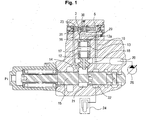
- As illustrated in FIGS. 1 and 2, a conventional hydraulic circuit of an option device for an excavator includes variable displacement
hydraulic pump 26; an option device 24 (e.g., a breaker and so on) connected to thehydraulic pump 26; afirst spool 15 installed in a flow path between thehydraulic pump 26 and theoption device 24 and shifted to control hydraulic fluid being supplied to theoption device 24 through anoption port 22 in response to a pilot signal pressure Pi applied thereto; apoppet 14 installed in a flow path between thehydraulic pump 26 and thefirst spool 15 to control hydraulic fluid fed from thehydraulic pump 26 to theoption device 24 when thefirst spool 15 is shifted; apiston 13 elastically supported in aback pressure chamber 17 of thepoppet 14; and asecond spool 3 shifted to control hydraulic fluid fed from thehydraulic pump 26 to theback pressure chamber 17 of thepoppet 14 through aflow path 23 connected to theback pressure chamber 17, in response to a difference between a pressure of an inlet part of the first spool and a sum of a pressure of an outlet part of thefirst spool 15 and an elastic force of avalve spring 5. - The conventional hydraulic circuit of an option device for an excavator further includes a
first orifice 13a formed in thepiston 13 and controlling hydraulic fluid fed from thehydraulic pump 26 to theback pressure chamber 17 of thepoppet 14 when thesecond spool 3 is shifted; asecond orifice 30 formed in aflow path 23 between thesecond spool 3 and aback pressure chamber 29 of thepiston 13, and controlling hydraulic fluid fed from thehydraulic pump 26 to theback pressure chamber 29 when thesecond spool 3 is shifted; and athird orifice 31 installed in aflow path 16 having an inlet part connected to a flow path between thefirst spool 15 and thepoppet 14 and an outlet part connected to thesecond spool 3, and controlling hydraulic fluid which is fed from thehydraulic pump 26 to shift thesecond spool 3. - In the drawing,
reference numeral 19 denotes a pilot flow path connected to asupply line 20 of thehydraulic pump 26 to receive a signal pressure for shifting thesecond spool 3. - Hereinafter, the operation of the conventional hydraulic circuit of an option device will be described.
- As shown in FIGS. 1 and 2, the hydraulic fluid fed from the
hydraulic pump 26 is supplied to thesupply line 20 and thepilot flow path 19. The hydraulic fluid fed to thesupply line 20 pushes thepoppet 14 upward as shown in the drawing. - The hydraulic fluid fed to the
back pressure chamber 17 of thepoppet 14 is supplied to achamber 21 through anorifice 14a of thepoppet 14, and thus thepoppet 14 is moved upward to be in contact with the piston 13 (in this case, theelastic member 12 is compressed). Accordingly, the hydraulic fluid on thesupply line 20 is supplied to thechamber 21. - When the pilot signal pressure Pi is applied to a left port of the
first spool 15, thefirst spool 15 is shifted in the right direction. The hydraulic fluid fed to thechamber 21 is supplied to theoption device 24 through theoption port 22 to drive theoption device 24. - In this case, when the
chamber 21 and theoption port 22 are connected together by the shifting of thefirst spool 15 and the hydraulic fluid is supplied to theoption device 24, a loss in pressure occurs between a pressure before the hydraulic fluid passes through thesecond spool 3 and a pressure after the hydraulic fluid passes through thesecond spool 3. - As illustrated in FIG. 1, the pressure, which is increased due to the shifting of the
first spool 15, is supplied to a left end of thesecond spool 3 along theflow path 16 connected to thechamber 21. When the hydraulic fluid is supplied to thesecond spool 3 after passing through thethird orifice 31 formed at an end part of theflow path 16, thesecond spool 3 is shifted in the right direction as shown in the drawing (FIG. 2 illustrates thesecond spool 3 that is shifted in the left direction). In this case, if it is assumed that the cross-sectional area of a diaphragm of the second spool is A1, a force that shifts thesecond spool 3 in the right direction is (A1×P1). - The pressure in the
option port 22 is applied to a right end of thesecond spool 3 after passing through thepilot flow path 18. Accordingly, thesecond spool 3 is shifted in the left direction as shown in the drawing (FIG. 2 illustrates thesecond spool 3 that is shifted in the right direction). In this case, if it is assumed that the cross-sectional area of the diaphragm of the second spool is A2, a force that shifts thesecond spool 3 in the left direction is (A2×P2)+F1 (which corresponds to the elastic force of the valve spring 5). - That is, the condition that the
second spool 3 is kept in its initial state (which corresponds to the state as illustrated in the drawing) is given as (A1×P1)<((A2×P2)+F1), and the condition that thesecond spool 3 is shifted in the right direction is given as (A1×P1)>((A2×P2)+F1). - In the case of shifting the
second spool 3 in the right direction as shown in FIG. 1, the hydraulic fluid is supplied to a left end of thesecond spool 3 through theflow path 16, and thesecond spool 3 is shifted in the right direction. The hydraulic fluid fed to thepilot flow path 19 is supplied to theback pressure chamber 29 of thepiston 13 after passing through thesecond spool 3, and a throughflow path 23 in order, and thus the piston is moved downward as shown in the drawing. Simultaneously, thepoppet 14 elastically installed by theelastic member 12 is moved downward. - The flow path between the
supply line 20 and thechamber 21 is blocked by thepoppet 14. AS the pressure in theflow path 16 is reduced, thesecond spool 3 is moved in the left direction as shown in FIG. 1. This corresponds to the state given as (A1 × P1) < ((A2 × P2) + F1). - When the
second spool 3 is shifted in the left direction as shown in the drawing, the supply of the pressure in thepilot flow path 19 to the throughflow path 23 is intercepted. As thepoppet 14 is moved upward as shown in the drawing, the hydraulic fluid fed from thehydraulic pump 26 is supplied to thesecond spool 3 via thechamber 21 and theflow path 16. This corresponds to the state given as (A1×P1)>((A2×P2)+F1). Accordingly, thesecond spool 3 is shifted in the right direction as shown in the drawing. - As illustrated in FIGS. 4A and 4B, a loss in pressure occurring between the signal pressures for shifting the
second spool 3 becomes constant due to the repeated shifting of thesecond spool 3. - That is, it is known that the flow rate Q of the hydraulic fluid being supplied to the
option device 24 is Q=(Cd×A×ΔP). Here, Q denotes the flow rate, Cd denotes a flow rate coefficient, A denotes an opening area of a spool (A = constant), and ΔP denotes a loss in pressure between P1 and P2 (ΔP = constant). - As described above, in the conventional hydraulic control valve structure of an option device, the hydraulic fluid fed from the
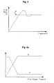
hydraulic pump 26 can be constantly supplied to theoption device 24 irrespective of the size of a load occurring in theoption device 24. - By contrast, as shown in FIG. 3, the flow rate of the hydraulic fluid being supplied to the option device is overshot (indicated as "a" in the drawing) in an initial control period of the option device, and then is stabilized with the lapse of a predetermined time. This may cause an abnormal operation of the option device in the initial operation period of the option device to lower the stability of the option device.
- In addition, option devices have different specifications depending on their manufacturers. Although the flow rate and pressure required for the option devices may differ, the flow rate of the hydraulic fluid being supplied to various kinds of option devices is not controlled, but the same flow rate is always applied thereto.
- Accordingly, even an operator having wide experience in operation cannot efficiently manipulate the option devices to lower the workability.
- Accordingly, the present invention has been made to solve the above-mentioned problems occurring in the prior art while advantages achieved by the prior art are maintained intact.
- One object of the present invention is to provide a hydraulic circuit of an option device for an excavator, which can constantly supply hydraulic fluid to the option device, irrespective of the size of a load occurring in the option device, to improve the manipulation, and can control respective flow rates required for various kinds of option devices.
- In an embodiment of the present invention, the hydraulic circuit can prevent the flow rate from being overshot in an initial control period of the option device, and thus the stability of the option device can be secured.
- In order to accomplish these objects, there is provided a hydraulic circuit of an option device for an excavator, according to one aspect of the present invention, which includes a variable hydraulic pump; an option device connected to the hydraulic pump; a first spool installed in a flow path between the hydraulic pump and the option device and shifted to control hydraulic fluid fed from the hydraulic pump to the option device; a poppet installed to open/close a flow path between the hydraulic pump and the first spool and controlling hydraulic fluid fed from the hydraulic pump to the option device when the first spool is shifted, and a piston elastically supported in a back pressure chamber of the poppet; an option spool installed in a flow path between the first spool and the option device and shifted to control hydraulic fluid fed to the option device via the first spool; a second spool shifted to control hydraulic fluid fed from the hydraulic pump to the back pressure chamber of the poppet via a through flow path connected to the back pressure chamber of the poppet, in response to a difference between a pressure of an inlet part of the first spool and a sum of a pressure of an outlet part of the first spool and an elastic force of a valve spring; and a control means installed inside the poppet and controlling hydraulic fluid passing through an orifice of the poppet when the piston and the poppet are pressed by the hydraulic fluid fed from the hydraulic pump, through the shifting of the second spool; wherein in an initial control period of the option device, the flow rate of the hydraulic fluid fed from the back chamber of the poppet to the option device through the shifting of the second poppet is prevented from being increased over a predetermined flow rate set by the control means.
- The control means may include a shim placed in an inlet part of the orifice of the poppet and having a through hole formed in the center thereof to be connected to the orifice of the poppet, and a check valve installed inside the orifice of the poppet and having an orifice formed in the center thereof.
- The hydraulic circuit of an option device for an excavator may further include a first orifice formed in the piston and controlling the hydraulic fluid fed from the hydraulic pump to the back pressure chamber of the poppet when the second spool is shifted; a second orifice formed in a flow path between the second spool and the back pressure chamber of the piston and controlling the hydraulic fluid fed from the hydraulic pump to the back pressure chamber of the piston when the second spool is shifted; and a third orifice installed in a flow path having an inlet part connected to a flow path between the first spool and the poppet and an outlet part connected to the second spool, and controlling the hydraulic fluid fed from the hydraulic pump to shift the second spool.
- The above and other objects, features and advantages of the present invention will be more apparent from the following detailed description taken in conjunction with the accompanying drawings, in which:
- FIG. 1 is a sectional view of a conventional hydraulic circuit of an option device for an excavator;
- FIG. 2 is a hydraulic circuit diagram of a conventional option device for an excavator;
- FIG. 3 is a graph showing the control flow rate that is overshot in an initial control period of the conventional option device for an excavator;
- FIGS. 4A and 4B are graphs showing the flow rate change against pressure in the hydraulic circuit of an option device for an excavator;
- FIG. 5 is a sectional view of main parts extracted from a hydraulic circuit of an option device for an excavator according to an embodiment of the present invention;
- FIG. 6 is a sectional view of a flow rate control valve in a hydraulic circuit of an option device for an excavator according to an embodiment of the present invention; and
- FIG. 7 is a hydraulic circuit diagram of an option device for an excavator according to an embodiment of the present invention.
- Hereinafter, preferred embodiments of the present invention will be described with reference to the accompanying drawings. The matters defined in the description, such as the detailed construction and elements, are nothing but specific details provided to assist those of ordinary skill in the art in a comprehensive understanding of the invention, and thus the present invention is not limited thereto.
- As shown in FIGS. 5 to 7, a hydraulic circuit of an option device for an excavator according to an embodiment of the present invention includes a variable
hydraulic pump 26; an option device 24 (e.g., a hammer, a shear, a breaker, and so forth) connected to thehydraulic pump 26; afirst spool 15 installed in a flow path between thehydraulic pump 26 and theoption device 24 and shifted to control hydraulic fluid being supplied from thehydraulic pump 26 to theoption device 24 in response to a pilot signal pressure Pi applied thereto; apoppet 14 installed to open/close aflow path 20 between thehydraulic pump 26 and thefirst spool 15 and controlling hydraulic fluid fed from thehydraulic pump 26 to theoption device 24 when thefirst spool 15 is shifted, and apiston 13 elastically supported by an elastic member 12 (e.g., a compression coil spring) in aback pressure chamber 17 of thepoppet 14; anoption spool 25 installed in aflow path 22 between thefirst spool 15 and theoption device 24 and shifted to control hydraulic fluid fed to theoption device 24 via thefirst spool 15 in response to pilot signal pressures 5pa4 and 5pb4; asecond spool 3 shifted to control hydraulic fluid fed from thehydraulic pump 26 to theback pressure chamber 17 of thepoppet 14 via a throughflow path 23 connected to theback pressure chamber 17 of thepoppet 14, in response to a difference between a pressure of an inlet part of thefirst spool 15 and a sum of a pressure of an outlet part of thefirst spool 15 and an elastic force of avalve spring 5; and a control means installed inside thepoppet 14 and controlling hydraulic fluid passing through anorifice 14a of thepoppet 14 when thepiston 13 and thepoppet 14 are pressed by the hydraulic fluid fed from thehydraulic pump 26, through the shifting of thesecond spool 3. - The control means includes a
shim 14c placed on an inlet part of theorifice 14a of the poppet and having a through hole 14-3 formed in the center thereof to be connected to theorifice 14a of thepoppet 14, and acheck valve 14b installed inside theorifice 14a of thepoppet 14 and having an orifice 14-2 formed in the center thereof. - The hydraulic circuit of an option device for an excavator according to an embodiment of the present invention further includes a
first orifice 13a formed in thepiston 13 and controlling the hydraulic fluid fed from thehydraulic pump 26 to theback pressure chamber 17 of thepoppet 14 when thesecond spool 3 is shifted; asecond orifice 30 formed in aflow path 23 between thesecond spool 3 and aback pressure chamber 29 of thepiston 13 and controlling the hydraulic fluid fed from thehydraulic pump 26 to theback pressure chamber 29 of thepiston 13 when thesecond spool 3 is shifted; and athird orifice 31 installed in aflow path 16 having an inlet part connected to a flow path between thefirst spool 15 and thepoppet 14 and an outlet part connected to thesecond spool 3, and controlling the hydraulic fluid fed from thehydraulic pump 26 to shift thesecond spool 3. - In the whole description of the present invention, the same drawing reference numerals as illustrated in FIG. 1 are used for the same elements across various figures, and the detailed description thereof will be omitted.
- Hereinafter, the operation of the hydraulic circuit of an option device for an excavator according to an embodiment of the present invention will be described with reference to the accompanying drawings.
- As shown in FIG. 7, the hydraulic fluid fed from the
hydraulic pump 26 is supplied to thesupply line 20 and thepilot flow path 19. The hydraulic fluid fed to thesupply line 20 pushes thepoppet 14 upward as shown in the drawing. Simultaneously, the hydraulic fluid pushes thecheck valve 14b installed inside theorifice 14a of thepoppet 14 upward, and moves the check valve up to the position of theshim 14c. - In this case, the hydraulic fluid fed to the
back pressure chamber 17 of thepoppet 14 is supplied to achamber 21 through an orifice 14-2 of thecheck valve 14b installed inside thepoppet 14. Accordingly, thepoppet 14 is moved upward to be in contact with the piston 13 (in this case, theelastic member 12 is compressed). - Accordingly, the hydraulic fluid on the
supply line 20 is supplied to thechamber 21. At this time, the hydraulic fluid moved to thechamber 21 is intercepted by thefirst spool 15 that is kept in a neutral state, and thus is not supplied to theoption device 24. - When the pilot signal pressure 5pa4 is applied to the
option spool 25, its inner spool is shifted in the left direction as shown in FIG. 7. Accordingly, the hydraulic fluid fed from thehydraulic pump 26 to the flow path 20-1 is intercepted by the shiftedoption spool 25, and the hydraulic fluid fed from thehydraulic pump 26 to theflow path 22 is supplied to theoption device 24 via a flow path 5A4. - As shown in FIG. 6, in the case where the pilot signal pressure Pi is applied to the left port of the
first spool 15, thefirst spool 15 is shifted in the right direction (while in FIG. 7, thefirst spool 15 is shifted in the left direction). The hydraulic fluid fed into thechamber 21 is supplied to theoption device 24 via theoption port 22, and thus the option device is driven. - That is, when the
first spool 15 is shifted by the pilot signal pressure Pi, the cross-sectional area of avariable notch part 27 formed on thefirst spool 15 is varied depending on the movement of thefirst spool 15. Accordingly, the flow rate of the hydraulic fluid fed to theoption device 24 through thefirst spool 15 can be controlled. - As shown in FIG. 6, when the hydraulic fluid fed from the
hydraulic pump 26 is supplied to theoption spool 25 via thefirst spool 15, a loss in pressure occurs between thechamber 21 and theoption port 22 by thevariable notch part 27 formed on the periphery of thefirst spool 15. In this case, if the flow rate of the hydraulic fluid fed from thechamber 21 to theoption port 22 through the shifting of thefirst spool 15 is increased, the pressure loss is also increased. - At this time, the hydraulic fluid having the pressure that is increased through the shifting of the
first spool 15 is supplied to the left end of thesecond spool 3 after passing through thethird orifice 31 of theflow path 16 connected to thechamber 21. Accordingly, thesecond spool 3 is shifted in the right direction as shown in the drawing (while in FIG. 7, thesecond spool 3 is shifted in the left direction). - In this case, if it is assumed that the cross-sectional area of a diaphragm of the second spool is A1, a force that shifts the
second spool 3 in the right direction is (A1×P1). - The pressure in the
option port 22 is applied to the right end of thesecond spool 3 after passing through thepilot flow path 18. Accordingly, thesecond spool 3 is shifted in the left direction as shown in FIG. 6 (while, in FIG. 7, thesecond spool 3 is shifted in the right direction). In this case, if it is assumed that the cross-sectional area of the diaphragm of thesecond spool 3 is A2, a force that shifts thesecond spool 3 in the left direction is (A2×P2)+F1 (which corresponds to the elastic force of the valve spring 5). - The condition that the
second spool 3 is kept in its initial state, i.e., in its non-shifted state, (which corresponds to the state as shown in FIG. 6) is given as (A1 × P1) < ((A2 × P2) + F1). - By contrast, the condition that the
second spool 3 is shifted in the right direction as shown in FIG. 6 is given as (A1 × P1) > ((A2 × P2) + F1). - In the case of shifting the
second spool 3 in the right direction as shown in FIG. 6, the hydraulic fluid fed to thepilot flow path 19 connected to thesupply line 20 is supplied to theback pressure chamber 29 of thepiston 13 after passing through thesecond spool 3 and a throughflow path 23 in order. Accordingly, thepiston 13 is moved downward as shown in the drawing. Simultaneously, thepoppet 14 elastically supported by theelastic member 12 is moved downward. - At this time, if the
second spool 3 is shifted and thepiston 13 is pressed by the hydraulic fluid fed from thehydraulic pump 26, the flow rate of the hydraulic fluid passing through theorifice 14a of thepoppet 14 can be reduced by theshim 14c and thecheck valve 14b installed in thepoppet 14. - That is, the hydraulic fluid fed from the
back pressure chamber 17 passes in order through a through hole 14-3 formed on theshim 14c placed in the inlet part of theorifice 14a of thepoppet 14 and an orifice 14-2 formed on thecheck valve 14b installed inside theorifice 14a of thepoppet 14. - Accordingly, at an initial operation of the
option device 24, the time when the hydraulic fluid fed from theback pressure chamber 17 passes through theorifice 14a of thepoppet 14 and the flow rate of the hydraulic fluid passing through theorifice 14a can be reduced. - By the movement of the
poppet 14, the flow path between thesupply line 20 and thechamber 21 is blocked. AS the pressure in theflow path 16 is reduced, thesecond spool 3 is moved in the left direction as shown in FIG. 6. This corresponds to the condition given as (A1×P1)<((A2×P2)+F1). - When the
second spool 3 is shifted in the left direction as shown in the drawing, the supply of the pressure in thepilot flow path 19 to the throughflow path 23 is intercepted. Accordingly, as thepoppet 14 is moved upward as shown in the drawing, the hydraulic fluid fed from thehydraulic pump 26 is supplied to the left end of thesecond spool 3 via thesupply line 20, thechamber 21 and theflow path 16. - This is, the condition that the
second spool 3 is shifted in the right direction as shown in the drawing is given as (A1×P1)>((A2×P2)+F1). Accordingly, thesecond spool 3 is shifted in the right direction as shown in the drawing. - Accordingly, as the repeated shifting of the
second spool 3 is performed, the loss in pressure occurring between thechamber 21 and theoption port 22 becomes constant. - As illustrated in FIGS. 4A and 4B, it is known that the flow rate Q of the hydraulic fluid being supplied to the
option device 24 is Q=(Cd×A×ΔP). Here, Q denotes the flow rate, Cd denotes a flow rate coefficient, A denotes an opening area of a spool (A = constant), and ΔP denotes a loss in pressure between P1 and P2 (ΔP = constant). - As described above, when an excavator having option devices mounted thereon operates, the hydraulic fluid fed from the
hydraulic pump 26 can be constantly supplied to theoption device 24, irrespective of the size of a load occurring in theoption device 24. Also, the flow rates required for various kinds of option devices can be respectively controlled. In addition, the flow rate of the hydraulic fluid being supplied to theoption device 24 in an initial control period of the option device can be prevented from being overshot over the predetermined flow rate. - From the foregoing, it will be apparent that the hydraulic circuit of an option device for an excavator according to an embodiment of the present invention has the following advantages.
- The hydraulic circuit can constantly supply the hydraulic fluid to the option device, irrespective of the size of a load of the option device, and thus the operation speed of the option device is kept constant to improve the manipulation. Also, the hydraulic circuit can respectively control the flow rates required for various kinds of option devices.
- The hydraulic circuit can prevent the flow rate from being overshot in an initial control period of the option device, and thus the stability of the option device can be secured.
- Although preferred embodiment of the present invention has been described for illustrative purposes, those skilled in the art will appreciate that various modifications, additions and substitutions are possible, without departing from the scope and spirit of the invention as disclosed in the accompanying claims.
Claims (5)
- A hydraulic circuit of an option device for an excavator, comprising:a variable hydraulic pump;an option device connected to the hydraulic pump;a first spool installed in a flow path between the hydraulic pump and the option device and shifted to control hydraulic fluid fed from the hydraulic pump to the option device;a poppet installed to open/close a flow path between the hydraulic pump and the first spool and controlling hydraulic fluid fed from the hydraulic pump to the option device when the first spool is shifted, and a piston elastically supported in a back pressure chamber of the poppet;an option spool installed in a flow path between the first spool and the option device and shifted to control hydraulic fluid fed to the option device via the first spool;a second spool shifted to control hydraulic fluid fed from the hydraulic pump to the back pressure chamber of the poppet via a through flow path connected to the back pressure chamber of the poppet, in response to a difference between a pressure of an inlet part of the first spool and a sum of a pressure of an outlet part of the first spool and an elastic force of a valve spring; anda control means installed inside the poppet and controlling hydraulic fluid passing through an orifice of the poppet when the piston and the poppet are pressed by the hydraulic fluid fed from the hydraulic pump, through the shifting of the second spool;wherein in an initial control period of the option device, the flow rate of the hydraulic fluid fed from the back chamber of the poppet to the option device through the shifting of the second poppet is prevented from being increased over a predetermined flow rate set by the control means.
- The hydraulic circuit of claim 1, wherein the control means comprises:a shim placed in an inlet part of the orifice of the poppet and having a through hole formed in the center thereof to be connected to the orifice of the poppet; anda check valve installed inside the orifice of the poppet and having an orifice formed in the center thereof.
- The hydraulic circuit of claim 1, further comprising a first orifice formed in the piston and controlling the hydraulic fluid fed from the hydraulic pump to the back pressure chamber of the poppet when the second spool is shifted.
- The hydraulic circuit of claim 1, further comprising a second orifice formed in a flow path between the second spool and the back pressure chamber of the piston and controlling the hydraulic fluid fed from the hydraulic pump to the back pressure chamber of the piston when the second spool is shifted.
- The hydraulic circuit of claim 1, further comprising a third orifice installed in a flow path having an inlet part connected to a flow path between the first spool and the poppet and an outlet part connected to the second spool, and controlling the hydraulic fluid fed from the hydraulic pump to shift the second spool.
Applications Claiming Priority (1)
| Application Number | Priority Date | Filing Date | Title |
|---|---|---|---|
| KR1020060082265A KR100800081B1 (en) | 2006-08-29 | 2006-08-29 | Hydraulic Circuit of Excavator Option |
Publications (3)
| Publication Number | Publication Date |
|---|---|
| EP1895059A2 true EP1895059A2 (en) | 2008-03-05 |
| EP1895059A3 EP1895059A3 (en) | 2015-08-05 |
| EP1895059B1 EP1895059B1 (en) | 2017-01-25 |
Family
ID=38775551
Family Applications (1)
| Application Number | Title | Priority Date | Filing Date |
|---|---|---|---|
| EP07012747.7A Ceased EP1895059B1 (en) | 2006-08-29 | 2007-06-29 | Hydraulic circuit of option device for excavator |
Country Status (5)
| Country | Link |
|---|---|
| US (1) | US8113233B2 (en) |
| EP (1) | EP1895059B1 (en) |
| JP (1) | JP5124207B2 (en) |
| KR (1) | KR100800081B1 (en) |
| CN (1) | CN101135324B (en) |
Families Citing this family (9)
| Publication number | Priority date | Publication date | Assignee | Title |
|---|---|---|---|---|
| KR100974273B1 (en) * | 2007-09-14 | 2010-08-06 | 볼보 컨스트럭션 이키프먼트 홀딩 스웨덴 에이비 | Flow control device for construction equipment |
| US8684037B2 (en) * | 2009-08-05 | 2014-04-01 | Eaton Corportion | Proportional poppet valve with integral check valve |
| WO2011145755A1 (en) * | 2010-05-17 | 2011-11-24 | 볼보 컨스트럭션 이큅먼트 에이비 | Hydraulic control valve for construction machinery |
| KR101094710B1 (en) | 2010-11-10 | 2011-12-16 | 주식회사 고려다이캐스팅기계 | Flow control valve |
| CN103299088A (en) * | 2010-12-28 | 2013-09-11 | 沃尔沃建造设备有限公司 | Holding valve for construction equipment |
| BR112014032589A2 (en) * | 2012-07-19 | 2017-06-27 | Volvo Constr Equip Ab | flow control valve for construction machinery |
| DE112013006593T5 (en) | 2013-02-05 | 2015-12-31 | Volvo Construction Equipment Ab | Pressure control valve for a construction machine |
| US20160221171A1 (en) * | 2015-02-02 | 2016-08-04 | Caterpillar Inc. | Hydraulic hammer having dual valve acceleration control system |
| WO2017122836A1 (en) * | 2016-01-11 | 2017-07-20 | 볼보 컨스트럭션 이큅먼트 에이비 | Hydraulic system for construction equipment |
Family Cites Families (16)
| Publication number | Priority date | Publication date | Assignee | Title |
|---|---|---|---|---|
| US3952771A (en) * | 1975-01-08 | 1976-04-27 | Zahnradfabrik Friedrichshafen Ag | Relief valves with pilot valves |
| US4531543A (en) * | 1983-06-20 | 1985-07-30 | Ingersoll-Rand Company | Uni-directional flow, fluid valve |
| KR920006546B1 (en) * | 1988-03-23 | 1992-08-08 | 히다찌 겐끼 가부시기가이샤 | Hydraulic Drive |
| US5137254A (en) * | 1991-09-03 | 1992-08-11 | Caterpillar Inc. | Pressure compensated flow amplifying poppet valve |
| US5207059A (en) * | 1992-01-15 | 1993-05-04 | Caterpillar Inc. | Hydraulic control system having poppet and spool type valves |
| KR0185493B1 (en) * | 1996-03-30 | 1999-04-01 | 토니헬샴 | Flow merging apparatus for heavy equipment |
| KR100198158B1 (en) * | 1996-12-31 | 1999-06-15 | 추호석 | Actuator hydraulic system for heavy equipment |
| JP2002004341A (en) * | 2000-06-20 | 2002-01-09 | Sumitomo (Shi) Construction Machinery Manufacturing Co Ltd | Hydraulic circuit for switching actuators of civil and construction machinery |
| KR100406275B1 (en) * | 2000-12-14 | 2003-11-17 | 볼보 컨스트럭션 이키프먼트 홀딩 스웨덴 에이비 | hydraulic circuit for heavy equipment option device |
| KR100402231B1 (en) * | 2000-12-21 | 2003-10-17 | 대우종합기계 주식회사 | Hydraulic circuit for excavator with an option device |
| KR20030052031A (en) * | 2001-12-20 | 2003-06-26 | 볼보 컨스트럭션 이키프먼트 홀딩 스웨덴 에이비 | control apparatus of hydraulic valve for construction heavy equipment |
| US6675904B2 (en) * | 2001-12-20 | 2004-01-13 | Volvo Construction Equipment Holding Sweden Ab | Apparatus for controlling an amount of fluid for heavy construction equipment |
| KR100559291B1 (en) * | 2003-06-25 | 2006-03-15 | 볼보 컨스트럭션 이키프먼트 홀딩 스웨덴 에이비 | Hydraulic Circuit for Heavy Equipment Option |
| DE10345712A1 (en) * | 2003-10-01 | 2005-04-21 | Bosch Rexroth Ag | Pressure feed |
| WO2005075834A1 (en) * | 2004-02-05 | 2005-08-18 | Bosch Rexroth Ag | Metering orifice arrangement for a hydraulic current divider and current adding device |
| KR100631072B1 (en) * | 2005-06-27 | 2006-10-02 | 볼보 컨스트럭션 이키프먼트 홀딩 스웨덴 에이비 | Hydraulic Circuit for Heavy Equipment Option |
-
2006
- 2006-08-29 KR KR1020060082265A patent/KR100800081B1/en not_active Expired - Fee Related
-
2007
- 2007-06-21 US US11/821,109 patent/US8113233B2/en not_active Expired - Fee Related
- 2007-06-29 EP EP07012747.7A patent/EP1895059B1/en not_active Ceased
- 2007-07-13 CN CN2007101366053A patent/CN101135324B/en not_active Expired - Fee Related
- 2007-08-20 JP JP2007213543A patent/JP5124207B2/en not_active Expired - Fee Related
Also Published As
| Publication number | Publication date |
|---|---|
| KR100800081B1 (en) | 2008-02-01 |
| EP1895059B1 (en) | 2017-01-25 |
| CN101135324B (en) | 2012-02-01 |
| CN101135324A (en) | 2008-03-05 |
| JP5124207B2 (en) | 2013-01-23 |
| US20080053538A1 (en) | 2008-03-06 |
| JP2008057319A (en) | 2008-03-13 |
| US8113233B2 (en) | 2012-02-14 |
| EP1895059A3 (en) | 2015-08-05 |
Similar Documents
| Publication | Publication Date | Title |
|---|---|---|
| EP1895059B1 (en) | Hydraulic circuit of option device for excavator | |
| EP1975324B1 (en) | Hydraulic circuit for construction equipment | |
| EP2071195A2 (en) | Hydraulic circuit with load holding valves operated by external pilot pressure | |
| EP1927759A1 (en) | Double check valve having floating function | |
| EP2037048A2 (en) | Flow control apparatus for heavy construction equipment | |
| EP0559903A1 (en) | Valve device | |
| JP2005265062A (en) | Hydraulic control device for work machine | |
| EP1906030A2 (en) | Pressure control device for heavy equipment | |
| EP2573407A1 (en) | Hydraulic control valve for construction machinery | |
| US20170261011A1 (en) | Valve assembly | |
| US9657754B2 (en) | Hydraulic circuit | |
| EP1739313A2 (en) | Hydraulic circuit for option device of heavy construction equipment | |
| US7766042B2 (en) | Direct operated cartridge valve assembly | |
| CN105221399A (en) | With the oil pressure actuated system of failure safe function | |
| EP1568892B1 (en) | Flow control apparatus for construction heavy equipment | |
| JP2634969B2 (en) | Hydraulic drive and unload valve for civil engineering and construction machinery | |
| JP2001187903A (en) | Piping break control valve device | |
| CN110714507A (en) | Valve structure and construction machine | |
| JP2002276608A (en) | Hydraulic control device | |
| JPH10252706A (en) | Hydraulic control circuit | |
| JP6510910B2 (en) | Hydraulic drive | |
| JPH11294338A (en) | Control device for hydraulic pump | |
| JP2001027184A (en) | Safety device for pneumatic drive equipment | |
| JPH02138503A (en) | valve device | |
| JPH081205B2 (en) | Hydraulic circuit |
Legal Events
| Date | Code | Title | Description |
|---|---|---|---|
| PUAI | Public reference made under article 153(3) epc to a published international application that has entered the european phase |
Free format text: ORIGINAL CODE: 0009012 |
|
| AK | Designated contracting states |
Kind code of ref document: A2 Designated state(s): AT BE BG CH CY CZ DE DK EE ES FI FR GB GR HU IE IS IT LI LT LU LV MC MT NL PL PT RO SE SI SK TR |
|
| AX | Request for extension of the european patent |
Extension state: AL BA HR MK YU |
|
| PUAL | Search report despatched |
Free format text: ORIGINAL CODE: 0009013 |
|
| AK | Designated contracting states |
Kind code of ref document: A3 Designated state(s): AT BE BG CH CY CZ DE DK EE ES FI FR GB GR HU IE IS IT LI LT LU LV MC MT NL PL PT RO SE SI SK TR |
|
| AX | Request for extension of the european patent |
Extension state: AL BA HR MK RS |
|
| RIC1 | Information provided on ipc code assigned before grant |
Ipc: F15B 11/05 20060101ALI20150701BHEP Ipc: E02F 9/22 20060101ALI20150701BHEP Ipc: E02F 3/96 20060101AFI20150701BHEP Ipc: F15B 11/042 20060101ALI20150701BHEP |
|
| 17P | Request for examination filed |
Effective date: 20160204 |
|
| RBV | Designated contracting states (corrected) |
Designated state(s): AT BE BG CH CY CZ DE DK EE ES FI FR GB GR HU IE IS IT LI LT LU LV MC MT NL PL PT RO SE SI SK TR |
|
| AKX | Designation fees paid |
Designated state(s): DE FR GB IT |
|
| AXX | Extension fees paid |
Extension state: AL Extension state: HR Extension state: BA Extension state: RS Extension state: MK |
|
| GRAP | Despatch of communication of intention to grant a patent |
Free format text: ORIGINAL CODE: EPIDOSNIGR1 |
|
| INTG | Intention to grant announced |
Effective date: 20160923 |
|
| GRAS | Grant fee paid |
Free format text: ORIGINAL CODE: EPIDOSNIGR3 |
|
| GRAA | (expected) grant |
Free format text: ORIGINAL CODE: 0009210 |
|
| AK | Designated contracting states |
Kind code of ref document: B1 Designated state(s): DE FR GB IT |
|
| REG | Reference to a national code |
Ref country code: GB Ref legal event code: FG4D |
|
| REG | Reference to a national code |
Ref country code: DE Ref legal event code: R096 Ref document number: 602007049615 Country of ref document: DE |
|
| REG | Reference to a national code |
Ref country code: FR Ref legal event code: PLFP Year of fee payment: 11 |
|
| REG | Reference to a national code |
Ref country code: DE Ref legal event code: R097 Ref document number: 602007049615 Country of ref document: DE |
|
| PG25 | Lapsed in a contracting state [announced via postgrant information from national office to epo] |
Ref country code: IT Free format text: LAPSE BECAUSE OF FAILURE TO SUBMIT A TRANSLATION OF THE DESCRIPTION OR TO PAY THE FEE WITHIN THE PRESCRIBED TIME-LIMIT Effective date: 20170125 |
|
| PLBE | No opposition filed within time limit |
Free format text: ORIGINAL CODE: 0009261 |
|
| STAA | Information on the status of an ep patent application or granted ep patent |
Free format text: STATUS: NO OPPOSITION FILED WITHIN TIME LIMIT |
|
| 26N | No opposition filed |
Effective date: 20171026 |
|
| REG | Reference to a national code |
Ref country code: FR Ref legal event code: PLFP Year of fee payment: 12 |
|
| PGFP | Annual fee paid to national office [announced via postgrant information from national office to epo] |
Ref country code: GB Payment date: 20220621 Year of fee payment: 16 |
|
| PGFP | Annual fee paid to national office [announced via postgrant information from national office to epo] |
Ref country code: FR Payment date: 20220624 Year of fee payment: 16 |
|
| PGFP | Annual fee paid to national office [announced via postgrant information from national office to epo] |
Ref country code: DE Payment date: 20220628 Year of fee payment: 16 |
|
| REG | Reference to a national code |
Ref country code: DE Ref legal event code: R119 Ref document number: 602007049615 Country of ref document: DE |
|
| GBPC | Gb: european patent ceased through non-payment of renewal fee |
Effective date: 20230629 |
|
| PG25 | Lapsed in a contracting state [announced via postgrant information from national office to epo] |
Ref country code: DE Free format text: LAPSE BECAUSE OF NON-PAYMENT OF DUE FEES Effective date: 20240103 Ref country code: GB Free format text: LAPSE BECAUSE OF NON-PAYMENT OF DUE FEES Effective date: 20230629 |
|
| PG25 | Lapsed in a contracting state [announced via postgrant information from national office to epo] |
Ref country code: FR Free format text: LAPSE BECAUSE OF NON-PAYMENT OF DUE FEES Effective date: 20230630 |