EP1894839A2 - A valve defining modulated and unmodulated flow paths - Google Patents
A valve defining modulated and unmodulated flow paths Download PDFInfo
- Publication number
- EP1894839A2 EP1894839A2 EP20070253381 EP07253381A EP1894839A2 EP 1894839 A2 EP1894839 A2 EP 1894839A2 EP 20070253381 EP20070253381 EP 20070253381 EP 07253381 A EP07253381 A EP 07253381A EP 1894839 A2 EP1894839 A2 EP 1894839A2
- Authority
- EP
- European Patent Office
- Prior art keywords
- valve
- flow path
- inlet
- heat exchanger
- air
- Prior art date
- Legal status (The legal status is an assumption and is not a legal conclusion. Google has not performed a legal analysis and makes no representation as to the accuracy of the status listed.)
- Granted
Links
Images

Classifications
-
- B—PERFORMING OPERATIONS; TRANSPORTING
- B64—AIRCRAFT; AVIATION; COSMONAUTICS
- B64D—EQUIPMENT FOR FITTING IN OR TO AIRCRAFT; FLIGHT SUITS; PARACHUTES; ARRANGEMENT OR MOUNTING OF POWER PLANTS OR PROPULSION TRANSMISSIONS IN AIRCRAFT
- B64D37/00—Arrangements in connection with fuel supply for power plant
- B64D37/32—Safety measures not otherwise provided for, e.g. preventing explosive conditions
-
- Y—GENERAL TAGGING OF NEW TECHNOLOGICAL DEVELOPMENTS; GENERAL TAGGING OF CROSS-SECTIONAL TECHNOLOGIES SPANNING OVER SEVERAL SECTIONS OF THE IPC; TECHNICAL SUBJECTS COVERED BY FORMER USPC CROSS-REFERENCE ART COLLECTIONS [XRACs] AND DIGESTS
- Y10—TECHNICAL SUBJECTS COVERED BY FORMER USPC
- Y10T—TECHNICAL SUBJECTS COVERED BY FORMER US CLASSIFICATION
- Y10T137/00—Fluid handling
- Y10T137/2496—Self-proportioning or correlating systems
- Y10T137/2559—Self-controlled branched flow systems
- Y10T137/265—Plural outflows
-
- Y—GENERAL TAGGING OF NEW TECHNOLOGICAL DEVELOPMENTS; GENERAL TAGGING OF CROSS-SECTIONAL TECHNOLOGIES SPANNING OVER SEVERAL SECTIONS OF THE IPC; TECHNICAL SUBJECTS COVERED BY FORMER USPC CROSS-REFERENCE ART COLLECTIONS [XRACs] AND DIGESTS
- Y10—TECHNICAL SUBJECTS COVERED BY FORMER USPC
- Y10T—TECHNICAL SUBJECTS COVERED BY FORMER US CLASSIFICATION
- Y10T137/00—Fluid handling
- Y10T137/8593—Systems
- Y10T137/877—With flow control means for branched passages
-
- Y—GENERAL TAGGING OF NEW TECHNOLOGICAL DEVELOPMENTS; GENERAL TAGGING OF CROSS-SECTIONAL TECHNOLOGIES SPANNING OVER SEVERAL SECTIONS OF THE IPC; TECHNICAL SUBJECTS COVERED BY FORMER USPC CROSS-REFERENCE ART COLLECTIONS [XRACs] AND DIGESTS
- Y10—TECHNICAL SUBJECTS COVERED BY FORMER USPC
- Y10T—TECHNICAL SUBJECTS COVERED BY FORMER US CLASSIFICATION
- Y10T137/00—Fluid handling
- Y10T137/8593—Systems
- Y10T137/877—With flow control means for branched passages
- Y10T137/87788—With valve or movable deflector at junction
-
- Y—GENERAL TAGGING OF NEW TECHNOLOGICAL DEVELOPMENTS; GENERAL TAGGING OF CROSS-SECTIONAL TECHNOLOGIES SPANNING OVER SEVERAL SECTIONS OF THE IPC; TECHNICAL SUBJECTS COVERED BY FORMER USPC CROSS-REFERENCE ART COLLECTIONS [XRACs] AND DIGESTS
- Y10—TECHNICAL SUBJECTS COVERED BY FORMER USPC
- Y10T—TECHNICAL SUBJECTS COVERED BY FORMER US CLASSIFICATION
- Y10T137/00—Fluid handling
- Y10T137/8593—Systems
- Y10T137/877—With flow control means for branched passages
- Y10T137/87788—With valve or movable deflector at junction
- Y10T137/87812—Pivoted valve or deflector
Definitions
- the present invention relates to a valve. More particularly, the present invention relates to a fluidic or air valve defining at least a first flow path with a modulating device such as a disk or flapper and a second, unmodulated flow path.
- a modulating device such as a disk or flapper
- One method of suppressing fire and explosions in an aircraft fuel tank is to provide a non-explosive atmosphere within the fuel tank by replacing potentially combustible air in a fuel tank ullage (i.e., the space within the fuel tank unoccupied by fuel) with an inerting gas, such as nitrogen-enriched air (NEA).
- an inerting gas such as nitrogen-enriched air (NEA).
- NAA nitrogen-enriched air
- An onboard inerting system is often used to supply NEA (or another inerting gas) into the tank ullage when the demand arises (e.g., in order to increase the pressure inside the ullage in response to changing atmospheric conditions or to otherwise maintain the oxygen content in the ullage at or below a desirable level).
- the inerting system can typically include a nitrogen generating system (NGS) that separates nitrogen from high pressure air generated by a single compressor, or series of compressors within the system.
- NGS nitrogen generating system
- Ram air i.e., air from outside the aircraft
- Both ram air and compressor air flow through a heat exchanger to exchange heat.
- ram air is fed to the NGS through a single inlet duct.
- a component's modulating valve controls flow of ram air to the NGS, such as a plurality of heat exchangers.
- the NGS output level typically depends on the amount of inert air required to fill the fuel tank ullage to maintain an inert environment.
- the modulating valve helps to achieve various NGS nitrogen gas output levels by controlling the amount of ram air that is directed to the heat exchangers to cool the heat of compressed air from the compressors. The amount of heat transfer is dependent upon flow through the compressors to accommodate the NGS desired output.
- a dedicated constant flow of ram air is desirable for multiple purposes, such as cooling a compressor motor and/or because at least one of the plurality of heat exchangers requires a constant flow of air.
- both the constant flow and modulated flow of ram air must be provided through a single inlet duct leading to the valve.
- the present invention is a valve defining at least two adjacent flow paths, where the fluid flow rate through one flow path is modulated and the fluid flow rate through the other flow path is constant.
- the two flow paths share one inlet duct.
- the present invention is a valve defining at least a first modulated or variable flow path and a second, unmodulated or bypass flow path. While the inventive valve is described below in reference to a nitrogen generating system (NGS) for an aircraft, it should be understood that a valve in accordance with the present invention is suitable for any application in which it is desirable to implement a valve with at least two flow paths that share a common inlet portion.
- NGS nitrogen generating system
- FIG. 1 shows nitrogen generating system (NGS) 10, which includes inlet air valve 12, heat exchanger 14, motor 16, first compressor 18, and second compressor 20.
- GNS nitrogen generating system
- Valve 12 is mounted to the inlet header of heat exchanger 14, and includes valve body 30, baffle 32, modulating valve disk 34, actuator 36, and shaft 38.
- Valve 12 provides dual flow paths for ram air into heat exchanger 14.
- Bypass path B is shown to the right of baffle or separator 32, while variable path V (shown to the left of separator 32) has a variable opening controlled by modulating valve disk 34.
- the position of disk 34, and therefore the flow through variable path V is controlled by actuator 36, which rotates shaft 38, on which disk 34 is mounted.
- heat exchanger 14 includes intercooler 40 and main heat exchanger 42.
- Intercooler 40 is divided into two sections: intercooler section 40a, which is dedicated to cooling motor 16; and intercooler section 40b, which cools air from first compressor 18.
- Separator 32 is a vertical wall that extends into heat exchanger 14 to separate incoming ram air to intercooler 40. Separator 32 defines a constant flow opening for ram air to flow through section 40a of intercooler 40. The opposite side of separator 32 provides for ram air flow to enter intercooler section 40b through the variable opening of valve 12 controlled by disk 34. The variable flow of ram air also is delivered to main heat exchanger 42, and is used to cool air from second compressor 20.
- Heat exchanger 14 includes compressor air inlets 44 and 46, air outlet 48, air outlet 50, heat exchanger outlet 52, ram air outlet 54 (shown in FIG. 2), and mount 56.
- Motor 16 drives first compressor 18 and second compressor 20.
- Motor 16 includes air inlet 60 for receiving cooling air from outlet 48 of heat exchanger 14.
- First compressor 18 includes inlet 62 and outlet 64. Air from outlet 64 of first compressor 18 is delivered to inlet 44 of heat exchanger 14.
- Second compressor 20 includes inlet 66 and outlet 68. As shown in FIG. 1, second compressor inlet 66 receives air from outlet 50 of heat exchanger 14. Air from second compressor outlet 68 is delivered to inlet 46 of heat exchanger 14.
- air is drawn through inlet 62 into first compressor 18. Air flows out of outlet 64 of compressor 18 to inlet 44 of heat exchanger 14. The first compressor air flows through intercooler section 40a to outlet 48, where it is delivered to air inlet 60 of motor 16. The air passing through intercooler section 40a is cooled by ram air which has flowed through the open bypass section of valve 12.
- the air flowing through intercooler 40b from first compressor 18 is cooled by a variable flow of ram air that is modulated by disc 34.
- Output air from second compressor 20 is delivered through outlet 68 to inlet 46.
- the second compressor air flows through main heat exchanger 42 to heat exchanger outlet 52.
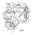
- FIG. 2 shows valve 12 and heat exchanger 14 separate from the other components of NGS 10.
- Valve 12 provides two separate passageways for ram air: unmodulated or bypass passage B and modulated or variable passage V.
- Bypass passage B allows a portion of ram air received at the inlet end of valve 12 to pass directly to intercooler 40a.
- Variable flow passage V controls the flow of air to intercooler 40b and main heat exchanger 42.
- the amount of air flowing through passage V is controlled by the position of disc 34.
- Actuator 36 rotates shaft 38 to position disc 34 in passage V.
- Disc 34 in combination with actuator 36 and shaft 38, operates as a butterfly valve assembly, which rotates around centerline CL of shaft 38.
- disc 34 is shown in a closed position, thereby blocking airflow through passage V.
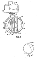
- disc 34 is shown in an open position, so that a portion of the ram air delivered to valve 12 can pass through passage V to intercooler section 40b and main heat exchanger 42.
- Valve 12 provides multiple flow paths that share a single inlet.
- Bypass passage B provides a constant airflow
- variable passage V provides a variable airflow, depending upon the position of valve disc 34.
- the flow passages run alongside each other through the valve body 30 separated only by the separating wall 32.
- the first passage V extends up to the inlet of the intercooler section 40b of heat exchanger 14 and to the inlet of main heat exchanger 42
- the second passage B extends up to the inlet of intercooler section 40a of heat exchanger 14.
- both passages B and V are shown as having a D-shaped opening, other shapes can also be used.
- FIG. 4 shows an embodiment in which separator 32 is curved and bypass passage B is crescent shaped in cross-section.
- the butterfly-type valve is shown in variable passage V, other types of flow modulating valves may be positioned within passage V. Examples include a ball valve, a gate valve, a spool valve, and a flapper valve.
- inlet valve 12 is described as being used to introduce ram air into NGS 10, it should be understood that an inlet valve in accordance with the principles of the present invention may be used in conjunction with other fluids, such as liquids, as well as other assemblies.
- the inlet valve may be formed of any suitable material, such as, but not limited to, metals, polyvinyl chloride, and other plastic materials.
Landscapes
- Engineering & Computer Science (AREA)
- Aviation & Aerospace Engineering (AREA)
- Lift Valve (AREA)
- Multiple-Way Valves (AREA)
- Valve Housings (AREA)
- External Artificial Organs (AREA)
Abstract
Description
- The present invention relates to a valve. More particularly, the present invention relates to a fluidic or air valve defining at least a first flow path with a modulating device such as a disk or flapper and a second, unmodulated flow path.
- One method of suppressing fire and explosions in an aircraft fuel tank is to provide a non-explosive atmosphere within the fuel tank by replacing potentially combustible air in a fuel tank ullage (i.e., the space within the fuel tank unoccupied by fuel) with an inerting gas, such as nitrogen-enriched air (NEA). An onboard inerting system is often used to supply NEA (or another inerting gas) into the tank ullage when the demand arises (e.g., in order to increase the pressure inside the ullage in response to changing atmospheric conditions or to otherwise maintain the oxygen content in the ullage at or below a desirable level). The inerting system can typically include a nitrogen generating system (NGS) that separates nitrogen from high pressure air generated by a single compressor, or series of compressors within the system. Ram air (i.e., air from outside the aircraft), independent of the high pressure air circuit, is the heat sink source to cool the hot compressed air generated by the compressors. Both ram air and compressor air flow through a heat exchanger to exchange heat.
- In one type of NGS, ram air is fed to the NGS through a single inlet duct. A component's modulating valve controls flow of ram air to the NGS, such as a plurality of heat exchangers. The NGS output level typically depends on the amount of inert air required to fill the fuel tank ullage to maintain an inert environment. The modulating valve helps to achieve various NGS nitrogen gas output levels by controlling the amount of ram air that is directed to the heat exchangers to cool the heat of compressed air from the compressors. The amount of heat transfer is dependent upon flow through the compressors to accommodate the NGS desired output.
- It has been found that in at least one particular NGS, a dedicated constant flow of ram air is desirable for multiple purposes, such as cooling a compressor motor and/or because at least one of the plurality of heat exchangers requires a constant flow of air. Given the space constraints in many aircraft, it may be undesirable to modify the NGS system to include more than one inlet duct to provide for modulating and constant ram flows to the heat exchanger. As a result, both the constant flow and modulated flow of ram air must be provided through a single inlet duct leading to the valve. There is a need for a valve design that provides multiple out flows, including at least one constant out flow, without requiring substantial modification of current NGS inlet duct dimensions.
- The present invention is a valve defining at least two adjacent flow paths, where the fluid flow rate through one flow path is modulated and the fluid flow rate through the other flow path is constant. The two flow paths share one inlet duct.
-
- FIG. 1 is a perspective view of a nitrogen generating system, which includes an air inlet valve in accordance with the present invention.
- FIG. 2 is a perspective view of the inlet valve and heat exchanger of the system of FIG. 1.
- FIG. 3 is a perspective view of the air inlet valve of FIG. 1 and with the valve modulating disk in an open position.
- FIG. 4 shows an embodiment with a curved separator.
- The present invention is a valve defining at least a first modulated or variable flow path and a second, unmodulated or bypass flow path. While the inventive valve is described below in reference to a nitrogen generating system (NGS) for an aircraft, it should be understood that a valve in accordance with the present invention is suitable for any application in which it is desirable to implement a valve with at least two flow paths that share a common inlet portion.
- FIG. 1 shows nitrogen generating system (NGS) 10, which includes
inlet air valve 12,heat exchanger 14,motor 16,first compressor 18, andsecond compressor 20. Valve 12 is mounted to the inlet header ofheat exchanger 14, and includesvalve body 30,baffle 32, modulatingvalve disk 34,actuator 36, andshaft 38. Valve 12 provides dual flow paths for ram air intoheat exchanger 14. Bypass path B is shown to the right of baffle orseparator 32, while variable path V (shown to the left of separator 32) has a variable opening controlled by modulatingvalve disk 34. The position ofdisk 34, and therefore the flow through variable path V, is controlled byactuator 36, which rotatesshaft 38, on whichdisk 34 is mounted. - As shown in FIG. 1,
heat exchanger 14 includesintercooler 40 andmain heat exchanger 42. Intercooler 40 is divided into two sections:intercooler section 40a, which is dedicated tocooling motor 16; andintercooler section 40b, which cools air fromfirst compressor 18.Separator 32 is a vertical wall that extends intoheat exchanger 14 to separate incoming ram air to intercooler 40.Separator 32 defines a constant flow opening for ram air to flow throughsection 40a ofintercooler 40. The opposite side ofseparator 32 provides for ram air flow to enterintercooler section 40b through the variable opening ofvalve 12 controlled bydisk 34. The variable flow of ram air also is delivered tomain heat exchanger 42, and is used to cool air fromsecond compressor 20.Heat exchanger 14 includescompressor air inlets air outlet 48,air outlet 50,heat exchanger outlet 52, ram air outlet 54 (shown in FIG. 2), andmount 56. -
Motor 16 drivesfirst compressor 18 andsecond compressor 20.Motor 16 includesair inlet 60 for receiving cooling air fromoutlet 48 ofheat exchanger 14. -
First compressor 18 includesinlet 62 andoutlet 64. Air fromoutlet 64 offirst compressor 18 is delivered toinlet 44 ofheat exchanger 14. -
Second compressor 20 includes inlet 66 andoutlet 68. As shown in FIG. 1, second compressor inlet 66 receives air fromoutlet 50 ofheat exchanger 14. Air fromsecond compressor outlet 68 is delivered toinlet 46 ofheat exchanger 14. - In operation, air is drawn through
inlet 62 intofirst compressor 18. Air flows out ofoutlet 64 ofcompressor 18 to inlet 44 ofheat exchanger 14. The first compressor air flows throughintercooler section 40a tooutlet 48, where it is delivered toair inlet 60 ofmotor 16. The air passing throughintercooler section 40a is cooled by ram air which has flowed through the open bypass section ofvalve 12. - A portion of the air delivered from
first compressor 18 toinlet 44 flows throughintercooler section 40b tooutlet 50, and then is supplied to inlet 66 ofsecond compressor 20. The air flowing throughintercooler 40b fromfirst compressor 18 is cooled by a variable flow of ram air that is modulated bydisc 34. - Output air from
second compressor 20 is delivered throughoutlet 68 toinlet 46. The second compressor air flows throughmain heat exchanger 42 toheat exchanger outlet 52. - FIG. 2 shows
valve 12 andheat exchanger 14 separate from the other components ofNGS 10. Valve 12 provides two separate passageways for ram air: unmodulated or bypass passage B and modulated or variable passage V. Bypass passage B allows a portion of ram air received at the inlet end ofvalve 12 to pass directly tointercooler 40a. - Variable flow passage V controls the flow of air to intercooler 40b and
main heat exchanger 42. The amount of air flowing through passage V is controlled by the position ofdisc 34.Actuator 36 rotatesshaft 38 to positiondisc 34 in passage V.Disc 34, in combination withactuator 36 andshaft 38, operates as a butterfly valve assembly, which rotates around centerline CL ofshaft 38. In FIG. 2,disc 34 is shown in a closed position, thereby blocking airflow through passage V. In FIG. 3,disc 34 is shown in an open position, so that a portion of the ram air delivered tovalve 12 can pass through passage V tointercooler section 40b andmain heat exchanger 42. - Valve 12 provides multiple flow paths that share a single inlet. Bypass passage B provides a constant airflow, while variable passage V provides a variable airflow, depending upon the position of
valve disc 34. The flow passages run alongside each other through thevalve body 30 separated only by theseparating wall 32. The first passage V extends up to the inlet of theintercooler section 40b ofheat exchanger 14 and to the inlet ofmain heat exchanger 42, and the second passage B extends up to the inlet ofintercooler section 40a ofheat exchanger 14. Although both passages B and V are shown as having a D-shaped opening, other shapes can also be used. For example, FIG. 4 shows an embodiment in whichseparator 32 is curved and bypass passage B is crescent shaped in cross-section. Similarly, although the butterfly-type valve is shown in variable passage V, other types of flow modulating valves may be positioned within passage V. Examples include a ball valve, a gate valve, a spool valve, and a flapper valve. - Although
inlet valve 12 is described as being used to introduce ram air intoNGS 10, it should be understood that an inlet valve in accordance with the principles of the present invention may be used in conjunction with other fluids, such as liquids, as well as other assemblies. Furthermore, the inlet valve may be formed of any suitable material, such as, but not limited to, metals, polyvinyl chloride, and other plastic materials. - The terminology used herein is for the purpose of description, not limitation. Specific structural and functional details disclosed herein are not to be interpreted as limiting, but merely as bases for teaching one skilled in the art to variously employ the present invention. Although the present invention has been described with reference to preferred embodiments, workers skilled in the art will recognize that changes may be made in form and detail without departing from the scope of the invention, which is defined by the claims.
Claims (24)
- A valve (12) comprising:an inlet portion configured to couple to a source of a fluid; anda body portion in fluidic communication with the inlet portion, the body portion defining:a modulated flow path (V); anda constant flow path (B) adjacent to the modulated flow path.
- The valve of claim 1, and further comprising:a modulating valve (34) disposed in the modulated flow path (V).
- The valve of claim 2, wherein the modulating valve is selected from a group consisting of disk, flapper, gate and ball valves.
- The valve of claim 1, 2 or 3, wherein the constant flow path has a shape selected from a group consisting of: a D-shape, and a crescent shape.
- The valve of claim 1, 2, 3 or 4, wherein the inlet portion and the body portion are constructed of a material selected from a group consisting of: metal and plastic.
- The valve of any preceding claim, wherein the fluid is air, gas, liquid or combinations thereof.
- The valve of any preceding claim and further comprising a separator (32) positioned between the modulated flow path and the constant flow path.
- The valve of claim 8 and further comprising a butterfly valve (34) positioned in the modulated flow path (V).
- The valve of claim 8 wherein the separator (32) comprises a vertical wall.
- A valve for providing a fluid to an apparatus, the valve comprising:an inlet;a first outlet;a second outlet;a first flow path (V) in fluidic communication with the inlet and the first outlet;a modulating valve (34) disposed within the first flow path and configured to control a rate of fluid flow through the first outlet; anda second flow path (B) adjacent to the first flow path and in fluidic communication with the inlet and the second outlet, wherein the second flow path is configured to provide a constant flow of fluid to the second outlet.
- The valve of claim 10, wherein the modulating valve is selected from a group consisting of a butterfly disk valve, a ball valve, a gate valve, a spool valve and a flapper valve.
- The valve of claim 10 or 11, wherein the inlet is configured to fluidically connect to a source of ram air.
- The valve of claim 10, 11 or 12, wherein the first flow path has a shape selected from a group consisting of: a D-shape and a crescent shape.
- The valve of any of claims 10 to 13, wherein the fluid is air.
- The valve of any of claims 10 to 14 and further comprising a separator (32) positioned between the first and second flow paths.
- The valve of claim 15 wherein the separator (32) comprises a vertical wall.
- A nitrogen generating system (10) for an aircraft, the nitrogen generating system comprising:a heat exchanger (14) including a first section and a second section; andan inlet valve (12) fluidically connected to the heat exchanger and configured to receive a flow of air, wherein the inlet valve comprises:a first flow path (B) configured to provide a constant flow of air to the first section (40a) of the heat exchanger; anda second flow path (V) configured to provide a variable flow of air to the second section (40b, 42) of the heat exchanger.
- The nitrogen generating system of claim 17, wherein the inlet valve comprises:a modulating valve (34) disposed within the second flow path for varying the flow of air through the second flow path.
- The nitrogen generating system of claim 18, wherein the modulating valve is selected from a group consisting of a butterfly valve and a ball valve.
- The nitrogen generating system of claim 18 or 19, wherein the heat exchanger includes a main heat exchanger (42) and an intercooler (40) having a first intercooler section (40a) and a second intercooler section (40b), wherein the first section of the heat exchanger includes the first intercooler section, and wherein the second section of the heat exchanger includes the second intercooler section and the main heat exchanger.
- The nitrogen generating system of claim 20 and further comprising:a first compressor (18) having an outlet (64) connected to an inlet (44) of the intercooler (40);a second compressor (20) having an inlet (66) connected to an outlet (50) of the second intercooler section (40b), and having an outlet (68) connected to an inlet (46) of the main heat exchanger (42); anda motor (16) for driving the first and second compressors and having an air inlet (60) connected to an outlet (48) of the first intercooler section (40a).
- The nitrogen generating system of any of claims 17 to 21 and further comprising a separator (32) positioned between the modulated flow path and the constant flow path.
- The nitrogen generating system of claim 22 and further comprising a butterfly valve (34) positioned in the modulated flow path.
- The nitrogen generating system of claim 22 or 23, wherein the separator (32) comprises a vertical wall.
Applications Claiming Priority (1)
| Application Number | Priority Date | Filing Date | Title |
|---|---|---|---|
| US11/511,940 US7584782B1 (en) | 2006-08-28 | 2006-08-28 | Valve defining modulated and unmodulated flow paths |
Publications (3)
| Publication Number | Publication Date |
|---|---|
| EP1894839A2 true EP1894839A2 (en) | 2008-03-05 |
| EP1894839A3 EP1894839A3 (en) | 2012-02-01 |
| EP1894839B1 EP1894839B1 (en) | 2013-02-13 |
Family
ID=38895584
Family Applications (1)
| Application Number | Title | Priority Date | Filing Date |
|---|---|---|---|
| EP20070253381 Active EP1894839B1 (en) | 2006-08-28 | 2007-08-28 | A valve defining modulated and unmodulated flow paths |
Country Status (3)
| Country | Link |
|---|---|
| US (2) | US7584782B1 (en) |
| EP (1) | EP1894839B1 (en) |
| JP (1) | JP5080171B2 (en) |
Families Citing this family (13)
| Publication number | Priority date | Publication date | Assignee | Title |
|---|---|---|---|---|
| US8225849B2 (en) * | 2003-10-02 | 2012-07-24 | Behr Gmbh & Co. Kg | Charge intercooler for a motor vehicle |
| FR2923859B1 (en) * | 2007-11-15 | 2009-12-18 | Valeo Systemes Thermiques Branche Thermique Habitacle | HEAT EXCHANGER FOR AN AIR SUPPLY CIRCUIT FOR A MOTOR VEHICLE ENGINE |
| US9366342B2 (en) * | 2010-02-12 | 2016-06-14 | Hamilton Sundstrand Corporation | Poppet valve with linear area gain |
| US20110209769A1 (en) * | 2010-03-01 | 2011-09-01 | Chun Richard K | Thermally operated valve |
| US8439073B2 (en) | 2010-09-10 | 2013-05-14 | Hamilton Sundstrand Corporation | Gate valve |
| US9658005B2 (en) | 2010-11-18 | 2017-05-23 | Hamilton Sundstrand Corporation | Heat exchanger system |
| US8727312B2 (en) | 2011-04-21 | 2014-05-20 | Hamilton Sundstrand Corporation | Butterfly valve |
| US9016078B2 (en) * | 2011-11-17 | 2015-04-28 | The Boeing Company | Fuel tank flammability reduction and inerting system and methods thereof |
| US9027885B2 (en) | 2012-09-27 | 2015-05-12 | Hamilton Sundstrand Corporation | Nitrogen gas system with diverter valve |
| CN104685284B (en) * | 2012-09-28 | 2017-03-15 | 日东工器株式会社 | There is the negative joint of security function |
| US9206913B2 (en) | 2013-03-05 | 2015-12-08 | Hamilton Sundstrand Corporation | Check valve having petals with lift generating elements |
| EP3155267B1 (en) * | 2014-06-16 | 2019-05-01 | Solidsvac Pty Ltd | Pneumatic pump |
| EP3842619B1 (en) | 2019-12-23 | 2022-09-28 | Hamilton Sundstrand Corporation | Valve assembly for an active clearance control system |
Citations (4)
| Publication number | Priority date | Publication date | Assignee | Title |
|---|---|---|---|---|
| FR800214A (en) | 1935-01-02 | 1936-06-30 | Centralventilen Ab | Valve device for central heating systems |
| DE2946357A1 (en) | 1979-11-16 | 1981-05-21 | Dietz-Armaturen GmbH, 5060 Bergisch-Gladbach | Single heating pipe controller - has housing with divided channel terminating with thermostat valve and connection to heater |
| EP1669290A1 (en) | 2004-12-08 | 2006-06-14 | Hamilton Sundstrand Corporation | On-board inert gas generation system |
| US20060185514A1 (en) | 2005-02-24 | 2006-08-24 | Gregory Schwalm | On-board inert gas generation system with compressor surge protection |
Family Cites Families (26)
| Publication number | Priority date | Publication date | Assignee | Title |
|---|---|---|---|---|
| US3441993A (en) * | 1966-11-08 | 1969-05-06 | Willem Stelwagen | Apparatus for heat-treating travelling threadlike products |
| US4054151A (en) * | 1974-05-20 | 1977-10-18 | Buchler Instruments, Division Of Searle Diagnostics Inc. | Concentrating vortex shaker |
| US3965933A (en) * | 1974-11-15 | 1976-06-29 | Beaudin Patrick L | Air duct made from sheet metal stamping |
| US4121610A (en) | 1976-02-02 | 1978-10-24 | Ambac Industries Incorporated | Electrically operated proportional flow control hydraulic valve and manually operable remote control device therefor |
| US4195777A (en) * | 1977-02-03 | 1980-04-01 | Nippondenso Co., Ltd. | Hot water heating system |
| US4200124A (en) * | 1978-02-21 | 1980-04-29 | Eaton Corporation | Valve assembly |
| FR2492979A1 (en) * | 1980-10-24 | 1982-04-30 | Cit Alcatel | GAS TANK VALVE WITH EXTENDED RANGE OF PRESSURES |
| US4526729A (en) * | 1983-01-26 | 1985-07-02 | Braun Alfred J | Vortex carburetor |
| US4535932A (en) * | 1984-06-11 | 1985-08-20 | Carrier Corporation | Actuator for a heating/cooling diffuser |
| US4699314A (en) * | 1986-12-17 | 1987-10-13 | Carrier Corporation | Actuator for a heating/cooling diffuser |
| ES1008822Y (en) * | 1988-12-09 | 1989-12-01 | Barnadas Solsona Miguel | PERFECTED DRAIN OF WATER STEAM CONDENSATES. |
| JP2816577B2 (en) * | 1989-10-31 | 1998-10-27 | 芳則 織部 | Method and apparatus for equalizing wind speed at each outlet of duct |
| US5265547A (en) * | 1990-10-04 | 1993-11-30 | Daws Gregory R | Diverting valve usable in apparatus for selectively creating tramlines |
| US5220944A (en) * | 1992-07-14 | 1993-06-22 | Ford Motor Company | Dual blend door assembly |
| US5533303A (en) * | 1995-04-18 | 1996-07-09 | Harvey; Robert B. | Downspout water conservation diversion adaptor |
| JP3787861B2 (en) * | 1995-07-14 | 2006-06-21 | 株式会社デンソー | Throttle valve device for internal combustion engine |
| EP0884539B1 (en) * | 1997-06-10 | 2003-04-23 | Hans Sasserath & Co Kg | Connector assembly for connecting an expansion vessel for hot sanitary water |
| DE10216537B3 (en) * | 2002-04-15 | 2004-02-05 | Visteon Global Technologies, Inc., Dearborn | Reversing device for flowing media, in particular switch valve for the exhaust gases of an internal combustion engine |
| JP4013249B2 (en) * | 2002-08-29 | 2007-11-28 | 株式会社デンソー | Throttle valve device for internal combustion engine |
| US7048231B2 (en) * | 2002-10-04 | 2006-05-23 | Shaw Aero Devices, Inc. | Increasing the performance of aircraft on-board inert gas generating systems by turbocharging |
| US6929056B2 (en) * | 2002-12-06 | 2005-08-16 | Modine Manufacturing Company | Tank manifold for internally mounted radial flow intercooler for a combustion air charger |
| US6913636B2 (en) * | 2002-12-17 | 2005-07-05 | Hamilton Sundstrand Corporation | Low power nitrogen enriched air generation system |
| US7081153B2 (en) * | 2003-12-02 | 2006-07-25 | Honeywell International Inc. | Gas generating system and method for inerting aircraft fuel tanks |
| US7306646B2 (en) * | 2004-04-08 | 2007-12-11 | Parker-Hannifin Corporation | Utilization of compressor surge control air in an aircraft on-board inert gas generating system |
| US7175692B2 (en) * | 2004-06-21 | 2007-02-13 | Hamilton Sundstrand | Ejector to reduce permeate backpressure of air separation module |
| US7828874B2 (en) * | 2008-09-12 | 2010-11-09 | Hamilton Sundstrand Corporation | On-board inert gas generation system with air separation module temperature control |
-
2006
- 2006-08-28 US US11/511,940 patent/US7584782B1/en active Active
-
2007
- 2007-08-22 JP JP2007215380A patent/JP5080171B2/en active Active
- 2007-08-28 EP EP20070253381 patent/EP1894839B1/en active Active
-
2009
- 2009-08-03 US US12/534,660 patent/US8307853B2/en active Active
Patent Citations (4)
| Publication number | Priority date | Publication date | Assignee | Title |
|---|---|---|---|---|
| FR800214A (en) | 1935-01-02 | 1936-06-30 | Centralventilen Ab | Valve device for central heating systems |
| DE2946357A1 (en) | 1979-11-16 | 1981-05-21 | Dietz-Armaturen GmbH, 5060 Bergisch-Gladbach | Single heating pipe controller - has housing with divided channel terminating with thermostat valve and connection to heater |
| EP1669290A1 (en) | 2004-12-08 | 2006-06-14 | Hamilton Sundstrand Corporation | On-board inert gas generation system |
| US20060185514A1 (en) | 2005-02-24 | 2006-08-24 | Gregory Schwalm | On-board inert gas generation system with compressor surge protection |
Also Published As
| Publication number | Publication date |
|---|---|
| JP5080171B2 (en) | 2012-11-21 |
| US20090241594A1 (en) | 2009-10-01 |
| US20090288724A1 (en) | 2009-11-26 |
| EP1894839A3 (en) | 2012-02-01 |
| JP2008057780A (en) | 2008-03-13 |
| EP1894839B1 (en) | 2013-02-13 |
| US7584782B1 (en) | 2009-09-08 |
| US8307853B2 (en) | 2012-11-13 |
Similar Documents
| Publication | Publication Date | Title |
|---|---|---|
| EP1894839B1 (en) | A valve defining modulated and unmodulated flow paths | |
| EP1695910B1 (en) | On-board inert gas generation system and method | |
| CN1894130B (en) | Cooling air supply system for aircraft and aircraft with the supply system | |
| EP3293383B1 (en) | Stepped high-pressure bleed control system | |
| EP3423721B1 (en) | Fluidic diode check valve | |
| EP1669290B1 (en) | On-board inert gas generation system | |
| EP2711297A2 (en) | Heat exchanger systems and methods for controlling airflow cooling | |
| CA2447351A1 (en) | Heat recovery ventilator | |
| US9254923B2 (en) | Aircraft fuel system and aircraft | |
| EP3045709B1 (en) | Valve system comprising a heat exchanger and method of cooling a valve controller | |
| EP0956480A1 (en) | Integral bypass valves and air cycle machine | |
| US20140299305A1 (en) | Heat Exchanger with Differentiated Resistance Flowpaths | |
| US20240157759A1 (en) | Fluid management device and thermal management system | |
| US9103300B2 (en) | Exhaust gas cooler for an exhaust gas recirculation system, and an exhaust gas recirculation system with such an exhaust gas cooler | |
| GB2496292A (en) | A system for controlling a gas turbine engine pneumatic valve | |
| EP4324666A1 (en) | Fluid management apparatus | |
| WO2006057944A2 (en) | Diverter for exhaust gas recirculation cooler | |
| EP1528351A3 (en) | Method and apparatus for heat exchange in an aircraft or other vehicle | |
| CN218439952U (en) | Assembly for compressing a gas | |
| US11046441B2 (en) | Adaptive plate-fin heat exchanger | |
| CN215851919U (en) | Aircraft fuel tank inerting and cooling system thereof | |
| EP4184109B1 (en) | Variable core heat exchanger with flow control | |
| EP4455467A1 (en) | Engine exhaust reverse flow prevention | |
| CN1361350A (en) | Cooling system and method for cooling fluid mechanical shell | |
| EP3800123B1 (en) | Air cycle machine with handed turbine bypass |
Legal Events
| Date | Code | Title | Description |
|---|---|---|---|
| PUAI | Public reference made under article 153(3) epc to a published international application that has entered the european phase |
Free format text: ORIGINAL CODE: 0009012 |
|
| AK | Designated contracting states |
Kind code of ref document: A2 Designated state(s): AT BE BG CH CY CZ DE DK EE ES FI FR GB GR HU IE IS IT LI LT LU LV MC MT NL PL PT RO SE SI SK TR |
|
| AX | Request for extension of the european patent |
Extension state: AL BA HR MK YU |
|
| PUAL | Search report despatched |
Free format text: ORIGINAL CODE: 0009013 |
|
| AK | Designated contracting states |
Kind code of ref document: A3 Designated state(s): AT BE BG CH CY CZ DE DK EE ES FI FR GB GR HU IE IS IT LI LT LU LV MC MT NL PL PT RO SE SI SK TR |
|
| AX | Request for extension of the european patent |
Extension state: AL BA HR MK RS |
|
| RIC1 | Information provided on ipc code assigned before grant |
Ipc: B64D 37/32 20060101AFI20111227BHEP |
|
| 17P | Request for examination filed |
Effective date: 20120801 |
|
| GRAP | Despatch of communication of intention to grant a patent |
Free format text: ORIGINAL CODE: EPIDOSNIGR1 |
|
| AKX | Designation fees paid |
Designated state(s): DE ES FR GB |
|
| RBV | Designated contracting states (corrected) |
Designated state(s): DE ES FR GB IT |
|
| GRAS | Grant fee paid |
Free format text: ORIGINAL CODE: EPIDOSNIGR3 |
|
| GRAA | (expected) grant |
Free format text: ORIGINAL CODE: 0009210 |
|
| AK | Designated contracting states |
Kind code of ref document: B1 Designated state(s): DE ES FR GB IT |
|
| REG | Reference to a national code |
Ref country code: GB Ref legal event code: FG4D |
|
| REG | Reference to a national code |
Ref country code: DE Ref legal event code: R096 Ref document number: 602007028390 Country of ref document: DE Effective date: 20130411 |
|
| PG25 | Lapsed in a contracting state [announced via postgrant information from national office to epo] |
Ref country code: ES Free format text: LAPSE BECAUSE OF FAILURE TO SUBMIT A TRANSLATION OF THE DESCRIPTION OR TO PAY THE FEE WITHIN THE PRESCRIBED TIME-LIMIT Effective date: 20130524 |
|
| PLBE | No opposition filed within time limit |
Free format text: ORIGINAL CODE: 0009261 |
|
| STAA | Information on the status of an ep patent application or granted ep patent |
Free format text: STATUS: NO OPPOSITION FILED WITHIN TIME LIMIT |
|
| PG25 | Lapsed in a contracting state [announced via postgrant information from national office to epo] |
Ref country code: IT Free format text: LAPSE BECAUSE OF FAILURE TO SUBMIT A TRANSLATION OF THE DESCRIPTION OR TO PAY THE FEE WITHIN THE PRESCRIBED TIME-LIMIT Effective date: 20130213 |
|
| 26N | No opposition filed |
Effective date: 20131114 |
|
| REG | Reference to a national code |
Ref country code: DE Ref legal event code: R097 Ref document number: 602007028390 Country of ref document: DE Effective date: 20131114 |
|
| PG25 | Lapsed in a contracting state [announced via postgrant information from national office to epo] |
Ref country code: DE Free format text: LAPSE BECAUSE OF NON-PAYMENT OF DUE FEES Effective date: 20140301 |
|
| REG | Reference to a national code |
Ref country code: DE Ref legal event code: R119 Ref document number: 602007028390 Country of ref document: DE Effective date: 20140301 |
|
| REG | Reference to a national code |
Ref country code: FR Ref legal event code: PLFP Year of fee payment: 10 |
|
| REG | Reference to a national code |
Ref country code: FR Ref legal event code: PLFP Year of fee payment: 11 |
|
| REG | Reference to a national code |
Ref country code: FR Ref legal event code: PLFP Year of fee payment: 12 |
|
| P01 | Opt-out of the competence of the unified patent court (upc) registered |
Effective date: 20230522 |
|
| PGFP | Annual fee paid to national office [announced via postgrant information from national office to epo] |
Ref country code: GB Payment date: 20250725 Year of fee payment: 19 |
|
| PGFP | Annual fee paid to national office [announced via postgrant information from national office to epo] |
Ref country code: FR Payment date: 20250725 Year of fee payment: 19 |