EP1894829A1 - Steering damper mounting structure for vehicle - Google Patents
Steering damper mounting structure for vehicle Download PDFInfo
- Publication number
- EP1894829A1 EP1894829A1 EP07015387A EP07015387A EP1894829A1 EP 1894829 A1 EP1894829 A1 EP 1894829A1 EP 07015387 A EP07015387 A EP 07015387A EP 07015387 A EP07015387 A EP 07015387A EP 1894829 A1 EP1894829 A1 EP 1894829A1
- Authority
- EP
- European Patent Office
- Prior art keywords
- steering damper
- bridge
- head pipe
- top bridge
- disposed
- Prior art date
- Legal status (The legal status is an assumption and is not a legal conclusion. Google has not performed a legal analysis and makes no representation as to the accuracy of the status listed.)
- Granted
Links
Images




Classifications
-
- B—PERFORMING OPERATIONS; TRANSPORTING
- B62—LAND VEHICLES FOR TRAVELLING OTHERWISE THAN ON RAILS
- B62K—CYCLES; CYCLE FRAMES; CYCLE STEERING DEVICES; RIDER-OPERATED TERMINAL CONTROLS SPECIALLY ADAPTED FOR CYCLES; CYCLE AXLE SUSPENSIONS; CYCLE SIDECARS, FORECARS, OR THE LIKE
- B62K21/00—Steering devices
- B62K21/08—Steering dampers
-
- F—MECHANICAL ENGINEERING; LIGHTING; HEATING; WEAPONS; BLASTING
- F16—ENGINEERING ELEMENTS AND UNITS; GENERAL MEASURES FOR PRODUCING AND MAINTAINING EFFECTIVE FUNCTIONING OF MACHINES OR INSTALLATIONS; THERMAL INSULATION IN GENERAL
- F16F—SPRINGS; SHOCK-ABSORBERS; MEANS FOR DAMPING VIBRATION
- F16F9/00—Springs, vibration-dampers, shock-absorbers, or similarly-constructed movement-dampers using a fluid or the equivalent as damping medium
- F16F9/06—Springs, vibration-dampers, shock-absorbers, or similarly-constructed movement-dampers using a fluid or the equivalent as damping medium using both gas and liquid
- F16F9/064—Units characterised by the location or shape of the expansion chamber
- F16F9/065—Expansion chamber provided on the upper or lower end of a damper, separately there from or laterally on the damper
-
- F—MECHANICAL ENGINEERING; LIGHTING; HEATING; WEAPONS; BLASTING
- F16—ENGINEERING ELEMENTS AND UNITS; GENERAL MEASURES FOR PRODUCING AND MAINTAINING EFFECTIVE FUNCTIONING OF MACHINES OR INSTALLATIONS; THERMAL INSULATION IN GENERAL
- F16F—SPRINGS; SHOCK-ABSORBERS; MEANS FOR DAMPING VIBRATION
- F16F9/00—Springs, vibration-dampers, shock-absorbers, or similarly-constructed movement-dampers using a fluid or the equivalent as damping medium
- F16F9/32—Details
- F16F9/44—Means on or in the damper for manual or non-automatic adjustment; such means combined with temperature correction
Definitions
- the present invention relates to a vehicular steering damper mounting structure that dampens a steering directional movement transmitted from a road surface to a handlebar via a front wheel and a front fork.
- a known vehicular steering damper mounting structure includes a tubular damper, as a steering damper, disposed between a head pipe on a side of a vehicle body frame and a bottom bridge on a side of a front fork (see, for example, JP-A-2005-96735 ).
- a vehicle includes a head pipe 6h disposed at a front end of a vehicle body frame 6.
- a front fork 2 is steerably mounted to the head pipe 6h via a steering stem 5.
- the front fork 2 includes left and right fork pipes 3, 3 connected by a fork bridge 4 including a top bridge 4a and a bottom bridge 4b.
- the fork pipes 3, 3 support a front wheel 1 via an axle.
- the steering stem 5 is mounted across the top bridge 4a and the bottom bridge 4b so as to extend vertically.
- a handlebar 7 is fitted to the top bridge 4a.
- a tubular damper 10 includes a damper case 11 and a damper rod 12 that slides inside the damper case 11.
- the damper case 11 has an end mounted to the head pipe 6h, while the damper rod 12 has an end mounted to the bottom bridge 4b.
- the tubular damper 10 is mounted between the head pipe 6h and the bottom bridge 4b, disposed at a position between the top bridge 4a and the bottom bridge 4b on a side of the bottom bridge 4b.
- a light unit such as a headlamp or the like
- the light unit is to be disposed at a space upward of the tubular damper 10. Disposing the light unit at this position results in a high optical axis of the light unit. As a result, a forward descent angle of the optical axis becomes greater when a predetermined position ahead of the vehicle is to be illuminated. This results in a smaller illumination range of a road surface in a longitudinal direction.
- a steering damper mounting structure of a vehicle includes a head pipe, a front fork, a fork bridge, and a steering damper.
- the head pipe forms part of a vehicle body.
- the front fork which suspends a front wheel, is steerably disposed on the head pipe.
- the fork bridge includes a top bridge and a bottom bridge, each of which connects a left member and a right member of the front fork.
- the steering damper is disposed on the fork bridge and the head pipe. The steering damper dampens a movement transmitted from a side of the front wheel to a handlebar.
- the steering damper is mounted to the head pipe and the top bridge and disposed on a side of the top bridge between the top bridge and the bottom bridge. Additionally, a light unit is disposed on a side of the bottom bridge between the top bridge and the bottom bridge.
- the arrangements according to the first aspect of the present invention achieve the following effects. Specifically, disposing the light unit closer to the bottom bridge between the top bridge and the bottom bridge results in the light unit being disposed at an even lower position of an upper portion of the front fork. This leads to a smaller forward descent angle of an optical axis of the light unit when the light unit is brought into action to illuminating a predetermined position forward of the vehicle.
- the steering damper is mounted to the head pipe and the top bridge and disposed on the side of the top bridge between the top bridge and the bottom bridge. This allows the light unit to be disposed near the bottom bridge between the top bridge and the bottom bridge without being affected by rotation of the steering damper. Moreover, the light unit does not overlap the steering damper in a forward direction of the vehicle. Accordingly, the light unit does not protrude forwardly and a structure is simplified at a forward upper portion of the vehicle, thus maintaining good appearance.
- the steering damper includes a main body having a cylinder, a piston movably inserted in the cylinder, and a rod mounted on the piston. Further, the main body has an end mounted on the head pipe and the rod has an end mounted on the top bridge.
- the main body includes an adjustment knob for use in adjusting a cross-sectional area of a path for oil packed in the cylinder. The adjustment knob is operable from an upward direction.
- the top bridge includes a protrusion that contacts the main body if an attempt is made to mount the main body on the top bridge or the rod on the head pipe, thereby preventing erroneous installation.
- the arrangements according to the second aspect of the present invention achieve the following effects. Specifically, if the main body is mounted to the top bridge or the rod is mounted to the head pipe, then the protrusion comes in contact with the main body, defying further assembly steps. Erroneous installation can thereby be prevented.
- the end of the main body is invariably mounted to the head pipe and the end of the rod is invariably mounted to the top bridge.
- the adjustment knob disposed on the main body for use in adjusting the cross-sectional area of the path for oil packed in the cylinder can be operable from the upward direction at all times.
- the end of the rod is mounted on the top bridge via the collar.
- the arrangement according to the third aspect of the present invention achieves the following effect. Specifically, a direct force acts less easily from the rod on the top bridge.
- the vehicle includes the number plate marked with the competition identification number.
- the number plate is disposed upwardly of the light unit and forwardly of the steering damper.
- the arrangement according to the fourth aspect of the present invention achieves the following effect. Specifically, the steering damper is covered with the number plate and protected from flying gravel or the like.
- the first portion of the steering damper attached to the head pipe and the second portion of the steering damper attached to the top bridge are each covered with the boot for minimizing entry of rainwater, dust, or the like.
- the arrangement according to the fifth aspect of the present invention achieves the following effect.
- the first portion of the steering damper attached to the head pipe and the second portion of the steering damper attached to the top bridge are pivotally moving portions which are less exposed to rainwater, dust, and the like.
- the boot includes an opening for draining water.
- the arrangement according to the sixth aspect of the present invention achieves the following effect. Specifically, water entering the boot is drained through this opening for draining water:
- the steering damper is mounted to the head pipe and the top bridge and disposed on the side of the top bridge between the top bridge and the bottom bridge. Additionally, there is disposed the light unit on the side of the bottom bridge between the top bridge and the bottom bridge. Consequently, the light unit is disposed at a lower position in front of the front fork. The forward descent angle of the optical axis of the light unit can thus be kept small, helping make wider an illumination range in a longitudinal direction of the road surface.
- the steering damper is mounted to the head pipe and the top bridge and disposed on the side of the top bridge between the top bridge and the bottom bridge. This additionally allows the light unit to be easily disposed near the bottom bridge between the top bridge and the bottom bridge without being affected by rotation of the steering damper. Moreover, the structure is simplified at the forward upper portion of the vehicle, thereby allowing the steering damper to be disposed without degrading appearance.
- the steering damper includes the main body having the cylinder, the piston movably inserted in the cylinder, and the rod mounted on the piston. Further, the main body has an end mounted on the head pipe and the rod has an end mounted on the top bridge.
- the main body includes the adjustment knob for use in adjusting the cross-sectional area of the path for oil packed in the cylinder. The adjustment knob is operable from an upward direction.
- the top bridge includes the protrusion that contacts the main body if an attempt is made to mount the main body on the top bridge or the rod on the head pipe, thereby preventing erroneous installation. By letting the protrusion prevent erroneous installation of the steering damper, the steering damper can be disposed such that the adjustment knob included in the main body is faced upward at all times for easy operation.
- the end of the rod is mounted on the top bridge via the collar. No direct force therefore acts from the rod on the top bridge. Wear in the top bridge can therefore be suppressed even if a material with a low hardness is used for the top bridge.
- the vehicle includes the number plate marked with the competition identification number.
- the number plate is disposed upwardly of the light unit and forwardly of the steering damper.
- the steering damper is thus covered with the number plate and can be protected from flying gravel or the like.
- the first portion of the steering damper attached to the head pipe and the second portion of the steering damper attached to the top bridge are each covered with the boot for minimizing entry of rainwater, dust, or the like.
- the first portion of the steering damper attached to the head pipe and the second portion of the steering damper attached to the top bridge, which are pivotally moved, are less exposed to rainwater, dust, and the like. A smooth pivotal movement of these portions can therefore be ensured for an extended period of time.
- the boot includes the opening for draining water. Accordingly, water entering the boot is drained through this opening for draining water. No water can therefore be accumulated inside the boot.
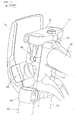
- Fig. 1 is a perspective view showing a front portion of a vehicle having a steering damper according to an embodiment of the present invention.
- Fig. 2 is a view for illustrating the front portion of the vehicle according to the embodiment of the present invention.
- Fig. 3 is a perspective view showing the front portion of the vehicle according to the embodiment of the present invention.
- Fig. 4 is a side elevational view showing the front portion of the vehicle according to the embodiment of the present invention.
- Fig. 5 is a cross-sectional view showing a steering damper mounting structure according to the embodiment of the present invention.
- Fig. 6 is a cross-sectional view showing the steering damper according to the embodiment of the present invention.
- Fig. 7 is a view for illustrating the operation of a protrusion for preventing erroneous installation of the steering damper according to the embodiment of the present invention.
- Fig. 8 is a view for illustrating a pivotal movement of the steering damper according to the embodiment of the present invention.
- Figs. 9(a) through 9(d) are views showing schematically mounting positions on, and pivotally moved postures of, both ends of the steering damper.
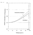
- Fig. 10 is a graph showing changes in the distance between the mounting portions of the steering damper during the steering action according to the embodiments of the present invention.
- Fig. 1 is a perspective view showing a front portion of a vehicle having a steering damper according to an embodiment of the present invention.
- a vehicle 10 is an off-road motorcycle.
- a handlebar 12 is fitted to an upper end of a front fork 13 that supports a front wheel at a lower end thereof.
- a steering damper (not shown) to be described in detail later is mounted on an upper portion of the front fork 13.
- a number plate 15 marked with a competition identification number is disposed so as to cover a forward area of the steering damper.
- reference numeral 21 represents a vehicle body frame serving as a framework for the vehicle 10.
- the front fork 13 is steerably mounted to a head pipe (not shown) disposed at a front end of the vehicle body frame 21.
- reference numeral 23 represents a fuel tank mounted at an upper portion of the vehicle body frame 21.
- Reference numeral 24 represents a cowl that covers a front side portion of a vehicle body.
- Reference numerals 25, 26 represent a clutch lever and a front wheel brake lever, respectively, attached to the handlebar 12.
- Reference numeral 27 represents a brake hose that transmits an operating force applied to the front wheel brake lever 26 to a brake caliper disposed on a side of the front wheel as brake hydraulic pressure.
- Reference numeral 28 represents a front fender that covers an area upward of the front wheel.
- Fig. 2 is a view for illustrating a front portion of the vehicle 10 according to the embodiment of the present invention.
- the front fork 13 includes a pair of left and right fork pipes 51, 52, a fork bridge 53, and a steering stem 57.
- the front wheel is mounted to lower ends of the fork pipes 51, 52 via an axle.
- the fork bridge 53 connects upper portions of the fork pipes 51, 52.
- the fork bridge 53 includes a top bridge 54 and a bottom bridge 56 formed of an aluminum alloy.
- the steering stem 57 which serves as a pivot, is extended across a central portion of each of the top bridge 54 and the bottom bridge 56.
- the steering stem 57 is rotatably mounted on a head pipe 61 disposed at a front end of the vehicle body frame 21 (see Fig. 1).
- the front fork 13, the handlebar 12 (see Fig. 1), and the head pipe 61 described above constitute a steering mechanism 58 for steering the front wheel.
- a steering damper 63 is mounted with bolts 65, 66 between the head pipe 61 and the top bridge 54.
- the steering damper 63 serves as a shock absorber that lessens a steering directional force suddenly transmitted to the front fork 13 and the handlebar 12 from a road surface via the front wheel.
- Fig. 3 is a perspective view (an arrow FRONT in Fig. 3 indicates a forward direction of the vehicle; the same applies hereunder) showing the front portion of the vehicle 10 according to the embodiment of the present invention.
- Fig. 3 shows that a light unit 68 is disposed forwardly of the head pipe 61 and downwardly of the steering damper 63.
- the light unit 68 is a lightweight competition lighting apparatus illuminating a road surface forward of the vehicle 10.
- the steering damper 63 can be protected from flying gravel or the like.
- Fig. 4 is a side elevational view showing the front portion of the vehicle 10 according to the embodiment of the present invention.
- Fig. 4 shows the following arrangements, specifically: the steering damper 63 is pivotally movably mounted to a front portion of the head pipe 61 and a front portion of the top bridge 54; the steering damper 63 is disposed between the top bridge 54 and the bottom bridge 56 on the side of the top bridge 54; the light unit 68 is disposed downwardly of the steering damper 63 and between the top bridge 54 and the bottom bridge 56 on the side of the bottom bridge 56; and a portion forward of an area from the top bridge 54 to the bottom bridge 56 is covered with the number plate 15 (a cross section thereof is shown in Fig. 4).
- the light unit 68 is mounted to the number plate 15 and exposed forwardly of the vehicle 10 through a window 15a formed in the number plate 15.
- the light unit 68 has an optical axis (that coincides with an axis of an electric bulb) 68A inclined at an illumination angle ⁇ relative to a horizontal line 70.
- the light unit 68 is disposed further upwardly, for example, at a position of the steering damper 63.
- the illumination angle involved becomes greater than the above-referenced illumination angle ⁇ .
- the light unit 68 is disposed to a lower level, so that the illumination angle ⁇ is even closer to the horizontal line 70. This allows the longitudinal illumination range on the road surface to be made greater.
- the steering damper 63 has a proximal end fitted to the head pipe 61 and a distal end fitted to the top bridge 54.
- the proximal end of the steering damper 63 is disposed closer to a side of the head pipe 61 than the distal end thereof. Accordingly, the steering damper 63 is mounted substantially perpendicularly as compared with the head pipe 61 that is inclined relative to a perpendicular direction. Consequently, the proximal end of the steering damper 63 attached to the head pipe 61 protrudes forwardly only a small amount. This allows the number plate 15 to be disposed even closer to the side of the head pipe 61, contributing to a compactly built front portion of the vehicle 10.
- Fig. 5 is a cross-sectional view (partly side elevational view) showing a steering damper mounting structure according to the embodiment of the present invention.
- An upper mounting portion 71 for the steering damper 63 mounted on the top bridge 54 includes an upper annular portion 72, a spherical plain bearing 73, and a snap ring 74.
- the spherical plain bearing 73 is fitted into the upper annular portion 72.
- the snap ring 74 secures the spherical plain bearing 73 to the upper annular portion 72.
- the upper mounting portion 71 is mounted via a collar 77 to an upper mounting portion 78 formed in the top bridge 54 with the bolt 65 passed through a bolt insertion hole 76 formed in the spherical plain bearing 73.
- reference numeral 79 represents a mounting surface formed on an end of the upper mounting portion 78.
- Reference numeral 81 represents internal threads formed in the upper mounting portion 78, in which the bolt 65 is screwed.
- Reference numeral 82 represents a protrusion (to be described in detail later) formed on a lower portion on the end of the upper mounting portion 78, the protrusion 82 preventing erroneous installation of the steering damper 63.
- the spherical plain bearing 73 includes an inner race 83 and an outer race 84.
- the inner race 83 has an outer surface 83a, on which part of a convex spherical surface is formed.
- the outer race 84 has an inner surface 84a, on which part of a concave spherical surface slidably fitted over the outer surface 83a of the inner race 83 is formed.
- the inner race 83 includes the bolt insertion hole 76, while the outer race 84 is fitted in the upper annular portion 72.
- reference numeral 65b represents a hexagon socket formed in the head 65a.
- Reference numeral 65c represents a large-diameter portion formed in the head 65a.
- the upper boot 86 includes a bolt fitting portion 86a, a collar fitting portion 86b, and an opening 86c.
- the bolt fitting portion 86a is fitted over the large-diameter portion 65c of the bolt 65.
- the collar fitting portion 86b is fitted to the collar 77.
- the opening 86c is for draining water.
- the upper boot 86 protects the upper mounting portion 71 from rainwater, dust, and the like. Rainwater entering the upper boot 86 is drained through the opening 86c.
- a lower mounting portion 91 of the steering damper 63 is mounted to the head pipe 61.
- the lower mounting portion 91 includes a lower annular portion 92, a spherical plain bearing 93, and a snap ring 94.
- the spherical plain bearing 93 is fitted into the lower annular portion 92.
- the snap ring 94 secures the spherical plain bearing 93 to the lower annular portion 92.
- the lower mounting portion 91 is mounted via a collar 98 to a lower mounting portion 97 formed in the head pipe 61 with the bolt 66 passed through a bolt insertion hole 96 formed in the spherical plain bearing 93.
- reference numeral 101 represents internal threads formed in the lower mounting portion 97, in which the bolt 66 is screwed.
- Reference numeral 102 represents a mounting surface formed on the lower mounting portion 97.
- the spherical plain bearing 93 includes an inner race 103 and an outer race 104.
- the inner race 103 has an outer surface 103a, on which part of a convex spherical surface is formed.
- the outer race 104 has an inner surface 104a, on which part of a concave spherical surface slidably fitted over the outer surface 103a of the inner race 103 is formed.
- the inner race 103 includes the bolt insertion hole 96, while the outer race 104 is fitted in the lower annular portion 92.
- the lower mounting portion 91, a head 66a of the bolt 66, and part of the collar 98 are covered with a lower boot 106 formed of rubber.
- the lower boot 106 includes a base fitting portion 106a, a head abutment portion 106b, a side opening 106c, and a lower opening 106d.
- the base fitting portion 106a is fitted over a base portion 91 a of the lower mounting portion 91.
- the head abutment portion 106b abuts on the head 66a of the bolt 66.
- the side opening 106c opens so as to circumvent the collar 98.
- the lower opening 106d disposed at a lower portion is for draining water.
- the lower boot 106 protects the lower mounting portion 91 from rainwater, dust, and the like. Rainwater entering the lower boot 106 is drained through the lower opening 106d.
- reference numeral 108 denotes a taper roller bearing disposed between the steering stem 57 and the head pipe 61.
- an axis 63A of the steering damper 63 is inclined by an angle ⁇ relative to a straight line 109 that extends in parallel with an axis 57A of the steering stem 57 (and the head pipe 61) in a side view.
- the axis 63A is inclined by the angle ⁇ relative to the axis 57A.
- the axis 63A of the steering damper 63 is inclined relative to the axis 57A and, moreover, the mounting surface 79 on the side of the upper mounting portion 71 extends in parallel with the axis 63A in the side view when the handlebar steering angle is zero. This makes greater a swingable range of the spherical plain bearing 73 in the upper mounting portion 71.
- reference numeral 65A represents an axis of the bolt 65
- reference numeral 66A represents an axis of the bolt 66.
- Fig. 6 is a cross-sectional view showing the steering damper 63 according to the embodiment of the present invention.
- the steering damper 63 includes a body 111, a piston 113, a piston rod 114, the upper mounting portion 71, a first cylinder end hermetic sealing portion 116, a free piston 118, a second cylinder end hermetic sealing portion 121, and a flow rate adjustment mechanism 127.
- the body 111 includes a plurality of tubes.
- the piston 113 is movably inserted in a first cylinder hole 112 formed in the body 111.
- the piston rod 114 is attached to the piston 113.
- the upper mounting portion 71 is mounted to a leading end of the piston rod 114.
- the first cylinder end hermetic sealing portion 116 is fitted slidably in the piston rod 114 and closes an opening of the first cylinder hole 112.
- the free piston 118 is movably inserted in a second cylinder hole 117 formed in the body 111.
- the second cylinder end hermetic sealing portion 121 closes an opening of the second cylinder hole 117.
- the flow rate adjustment mechanism 127 varies a damping force of the steering damper 63 by adjusting a flow rate of a hydraulic fluid flowing through a communication path 126 that provides fluid communication between a first hydraulic chamber 123 and a second hydraulic chamber 124 formed on either side of the piston 113 in the first cylinder hole 112.
- the lower mounting portion 91 is integrally formed with a lower end of the body 111.
- reference numeral 161 represents a communication hole providing communication between the first cylinder hole 112 and the second cylinder hole 117.
- Reference numerals 163, 164 represent a first chamber and a second chamber, respectively, formed on either side
- first hydraulic chamber 123, the second hydraulic chamber 124, and the first chamber 163 are filled with hydraulic fluid, while the second chamber 164 is filled with air.
- the flow rate adjustment mechanism 127 includes a needle 177, an adjustment shaft 178, a shaft support member 181, and an adjustment knob 187.
- the communication path 126 includes an upper communication hole 174 and a lower communication hole 175.
- the needle 177 advances into, or retracts from, a flow rate adjustment hole 176 formed at an upper end of the lower communication hole 175.
- the adjustment shaft 178 is connected to an end of the needle 177.
- the shaft support member 181 is mounted in the body 111 for rotatably supporting the adjustment shaft 178.
- the adjustment knob 187 is mounted to an end of the adjustment shaft 178 with a screw 182.
- the adjustment knob 187 can be stopped at every predetermined angle relative to the shaft support member 181 when a ball 184 pressed by a spring 183 fits into a specific one of a plurality of indentations 186, each being formed circumferentially at every predetermined angle.
- reference numeral 191 denotes internal threads formed in a lower longitudinal hole 192 in the body 111.
- the internal threads 191 are threadedly connected to external threads 177a formed on the needle 177.
- Reference numeral 193 denotes internal threads formed in an upper longitudinal hole 196 in the body 111.
- the internal threads 193 are threadedly connected to external threads 194 formed on the shaft support member 181.
- Reference numeral 197 denotes an O-ring fitted to an outer peripheral portion of the shaft support member 181.
- Reference numeral 198 denotes an O-ring mounted in an inner peripheral portion of the shaft support member 181.
- Reference numeral 201 denotes a retaining ring that prevents the adjustment knob 187 from coming off from the adjustment shaft 178.
- Adjusting the adjustment knob 187 rotates the needle 177 via the adjustment shaft 178. Turning the adjustment knob 187 also causes the needle 177 to advance into, or retract from, the flow rate adjustment hole 176 through the internal threads 191 and the external threads 177a threadedly connected thereto.
- the flow rate adjustment hole 176 is a female taper hole, while the needle 177 has a leading end that is a male taper to be engaged with the flow rate adjustment hole 176.
- Fig. 7 is a view for illustrating the operation of the protrusion 82 for preventing erroneous installation of the steering damper 63 according to the embodiment of the present invention.
- the protrusion 82 contacts a portion of the body 111 of the steering damper 63 close to the lower mounting portion 91. This prevents the steering damper 63 from being inclined further toward the side of the head pipe 61. Specifically, the axis 63A of the steering damper 63 is inclined less by an angle ⁇ relative to an axis 63B during correct installation.
- the protrusion 82 contacts the body 111, so that the other mounting portion of the steering damper 63, that is, the upper mounting portion 71 or the lower mounting portion 91, cannot be mounted. As such, erroneous installation of the steering damper 63 can be prevented.
- Fig. 8 is a view for illustrating a pivotal movement of the steering damper 63 according to the embodiment of the present invention.
- Fig. 8 is a bottom view showing the steering damper 63 and the top bridge 54 as viewed from a lower end side of the head pipe 61.
- Fig. 8 shows that the top bridge 54 rotates from a position of zero steering angles as shown by an imaginary line to a position of a steering angle ⁇ as shown by a solid line.
- Fig. 8 further shows that, as a result of the foregoing rotation of the top bridge 54, the steering damper 63 pivotally moves about the lower mounting portion 91, causing the upper mounting portion 71 to move arcuately as shown by an arrow.
- Figs. 9(a) through 9(d) are views showing schematically mounting positions on, and pivotally moved postures of, both ends of the steering damper 63.
- Fig. 9(a) is a side elevational view showing the embodiment of the present invention.
- Fig. 9(b) is a bottom view of.
- Fig. 9(c) is a side elevational view showing a comparative embodiment of the present invention.
- Fig. 9(d) is a bottom view of Fig. 9(c).
- a distance between the axis 57A and the lower mounting portion 91 (indicated by a black dot) of the steering damper 63 is R1
- a distance between the axis 57A and the upper mounting portion 71 (indicated by a blank dot) of the steering damper 63 is R2 (R2 > R1)
- a distance between the upper mounting portion 71 and the lower mounting portion 91, that is, a distance between the mounting portions is L1.
- the steering damper 63 (the steering damper 63 is shown by a broad solid line; the same applies hereunder) gradually pivotally moves, through a steering action, about the lower mounting portion 91 as shown by the arrow, causing the upper mounting portion 71 to move through the steering angle ⁇ .
- a steering damper 201 extends in parallel with an axis 57A. Further, a distance between the axis 57A and an upper mounting portion 202 (indicated by a blank dot) of the steering damper 201 equals a distance between the axis 57A and a lower mounting portion 203 (indicated by a blank dot) of the steering damper 201, each being referred to as R2.
- a distance between the upper mounting portion 202 and the lower mounting portion 203 that is, a distance between the mounting portions, is L2.
- the steering damper 201 gradually pivotally moves, through a steering action, about the lower mounting portion 203 as shown by the arrow, causing the upper mounting portion 202 to move through the steering angle ⁇ .
- Fig. 10 is a graph showing changes in the distance between the mounting portions of the steering damper during the steering action according to the embodiments of the present invention.
- the ordinate represents the distance L between the mounting portions of the steering damper, specifically, the distance between the upper and lower mounting portions, and the abscissa represents the steering angle ⁇ .
- Figs. 9(a) through 9(d) assume, for example, that the distance R1 is 60 mm, the distance R2 is 75 mm, the distance between the mounting portions L1 of the embodiment is 90 mm, the distance between the mounting portions L2 of the comparative embodiment is 90 mm, and the maximum steering angle ⁇ max is 47°. Changes in the distance between the mounting portions L (specifically, L1 and L2) at the steering angle ⁇ changing from 0 through ⁇ max° become greater as the steering angle ⁇ increases, as shown by the solid line for the embodiment and the broken line for the comparative embodiment. Further, the distance between the mounting portions L2 of the comparative embodiment remains greater at all times than the distance between the mounting portions L1 of the embodiment.
- the ordinate represents a stroke of the steering damper from an initial state if 90 mm is subtracted from the distance between the mounting portions L at each steering angle ⁇ .
- the stroke of the embodiment remains smaller than that of the comparative embodiment at all times, which promotes reduction in size of the steering damper of the embodiment.
- the steering damper mounting structure of the vehicle 10 which includes the head pipe 61, the front fork 13, the fork bridge 53, and the steering damper 63.
- the head pipe 61 forms part of a vehicle body.
- the front fork 13, which suspends the front wheel, is steerably disposed on the head pipe 61.
- the fork bridge 53 includes the top bridge 54 and the bottom bridge 56, each of which connects the left member and the right member of the front fork 13.
- the steering damper 63 is disposed on the fork bridge 53 and the head pipe 61. The steering damper 63 dampens the movement transmitted from the side of the front wheel to the handlebar 12.
- the steering damper 63 is mounted to the head pipe 61 and the top bridge 54 and disposed on the side of the top bridge 54 between the top bridge 54 and the bottom bridge 56. Additionally, the light unit 68 is disposed on the side of the bottom bridge 56 between the top bridge 54 and the bottom bridge 56.
- the foregoing arrangements result in the light unit 68 being disposed at a lower position in front of the front fork 13. This, in turn, leads to a smaller forward descent angle, specifically, the illumination angle ⁇ , of the optical axis 68A of the light unit 68, thus widening the illumination range in the longitudinal direction of the road surface.
- the steering damper 63 is mounted to the head pipe 61 and the top bridge 54 and disposed on the side of the top bridge 54 between the top bridge 54 and the bottom bridge 56. This allows the light unit 68 to be easily disposed near the bottom bridge 56 between the top bridge 54 and the bottom bridge 56 without being affected by rotation of the steering damper 63. Moreover, the structure is simplified at the forward upper portion of the vehicle and the steering damper 63 can be disposed without degrading appearance.
- the steering damper 63 includes the body 111 as a main body having the first cylinder hole 112 as a cylinder, the piston 113 movably inserted in the first cylinder hole 112, and the piston rod 114 as a rod mounted on the piston 113. Further, the body 111 has an end mounted on the head pipe 61 and the piston rod 114 has an end mounted on the top bridge 54.
- the body 111 includes the adjustment knob 187 for use in adjusting the cross-sectional area of the path for oil packed in the first cylinder hole 112. The adjustment knob 187 is operable from an upward direction.
- the top bridge 54 includes the protrusion 82 that contacts the body 111 if an attempt is made to mount the body 111 on the top bridge 54 or the piston rod 114 on the head pipe 61, thereby preventing erroneous installation.
- the steering damper 63 can thereby be disposed such that the adjustment knob 187 included in the body 111 is faced upwardly at all times for easy operation.
- the end of the piston rod 114 is mounted on the top bridge 54 via the collar 77.
- This arrangement results in no direct force acting from the piston rod 114 on the top bridge 54. Wear in the top bridge 54 can thereby be suppressed even if a material with a low hardness is used for the top bridge 54.
- the vehicle 10 includes the number plate 15 marked with the competition identification number.
- the number plate 15 is disposed upwardly of the light unit 68 and forwardly of the steering damper 63.
- the steering damper 63 is thus covered, at a forward area thereof, with the number plate 15 and can be protected from flying gravel or the like.
- the first portion (lower mounting portion 91) of the steering damper 63 attached to the head pipe 61 and the second portion (upper mounting portion 71) of the steering damper 63 attached to the top bridge 54 are covered with the lower boot 106 and the upper boot 86, respectively, for minimizing entry of rainwater, dust, or the like.
- the upper boot 86 and the lower boot 106 help make the upper mounting portion 71 and the lower mounting portion 91, which are pivotally moved, less exposed to rainwater, dust, and the like. A smooth pivotal movement of the upper mounting portion 71 and the lower mounting portion 91 can therefore be maintained for an extended period of time.
- the upper boot 86 and the lower boot 106 include the opening 86c and the lower opening 106d, respectively, as an opening for draining water.
- the steering damper of the vehicle according to the present invention is ideally applicable to a motorcycle.
- the invention is directed to a steering damper that ensures a wide longitudinal illumination range of a road surface when a light unit is provided and that facilitates layout of parts and simplifies structure without degrading appearance.
- a steering damper mounting structure of a vehicle 10 which includes a head pipe 61, a front fork 13, a fork bridge 53, and a steering damper 63.
- the head pipe 61 forms part of a vehicle body.
- the front fork 13, which suspends a front wheel, is steerably disposed on the head pipe 61.
- the fork bridge 53 includes a top bridge 54 and a bottom bridge 56, each of which connects a left member and a right member of the front fork 13.
- the steering damper 63 is mounted on the fork bridge 53 and the head pipe 61.
- the steering damper 63 dampens a movement transmitted from a side of the front wheel to a handlebar 12.
- the steering damper 63 is mounted to the head pipe 61 and the top bridge 54 and disposed on the side of the top bridge 54 between the top bridge 54 and the bottom bridge 56. Additionally, a light unit 68 is disposed on the side of the bottom bridge 56 between the top bridge 54 and the bottom bridge 56.
Landscapes
- Engineering & Computer Science (AREA)
- General Engineering & Computer Science (AREA)
- Mechanical Engineering (AREA)
- Fluid-Damping Devices (AREA)
Abstract
Description
- The present invention relates to a vehicular steering damper mounting structure that dampens a steering directional movement transmitted from a road surface to a handlebar via a front wheel and a front fork.
- A known vehicular steering damper mounting structure includes a tubular damper, as a steering damper, disposed between a head pipe on a side of a vehicle body frame and a bottom bridge on a side of a front fork (see, for example,
JP-A-2005-96735 - The arrangement disclosed in Figs. 1 and 2 of
JP-A-2005-96735 - A vehicle includes a head pipe 6h disposed at a front end of a vehicle body frame 6. A front fork 2 is steerably mounted to the head pipe 6h via a steering stem 5.
- The front fork 2 includes left and right fork pipes 3, 3 connected by a fork bridge 4 including a top bridge 4a and a bottom bridge 4b. The fork pipes 3, 3 support a front wheel 1 via an axle. The steering stem 5 is mounted across the top bridge 4a and the bottom bridge 4b so as to extend vertically. A handlebar 7 is fitted to the top bridge 4a.
- A
tubular damper 10 includes a damper case 11 and adamper rod 12 that slides inside the damper case 11. The damper case 11 has an end mounted to the head pipe 6h, while thedamper rod 12 has an end mounted to the bottom bridge 4b. - In the arrangement disclosed in Patent Document 1, the
tubular damper 10 is mounted between the head pipe 6h and the bottom bridge 4b, disposed at a position between the top bridge 4a and the bottom bridge 4b on a side of the bottom bridge 4b. If, for example, a light unit, such as a headlamp or the like, is to be disposed on an upper portion of the front fork 2, the light unit is to be disposed at a space upward of thetubular damper 10. Disposing the light unit at this position results in a high optical axis of the light unit. As a result, a forward descent angle of the optical axis becomes greater when a predetermined position ahead of the vehicle is to be illuminated. This results in a smaller illumination range of a road surface in a longitudinal direction. - It is possible to dispose the light unit at a position forward of the
tubular damper 10. This arrangement, however, requires that a space allowing thetubular damper 10 to rotate be secured. To allow for this space, the light unit is made to protrude forwardly, resulting in a complicated construction having only a forward upper portion of the vehicle protruding. It is then anticipated that appearance is impaired. - It is an object of the present invention to improve the vehicular steering damper mounting structure and to provide a steering damper that ensures a wide longitudinal illumination range of the road surface when a light unit is provided and that facilitates layout of parts and simplifies structure without degrading appearance.
- To achieve the foregoing object, according to a first aspect of the present invention, there is provided a steering damper mounting structure of a vehicle. The vehicle includes a head pipe, a front fork, a fork bridge, and a steering damper. The head pipe forms part of a vehicle body. The front fork, which suspends a front wheel, is steerably disposed on the head pipe. The fork bridge includes a top bridge and a bottom bridge, each of which connects a left member and a right member of the front fork. Further, the steering damper is disposed on the fork bridge and the head pipe. The steering damper dampens a movement transmitted from a side of the front wheel to a handlebar. In this steering damper mounting structure, the steering damper is mounted to the head pipe and the top bridge and disposed on a side of the top bridge between the top bridge and the bottom bridge. Additionally, a light unit is disposed on a side of the bottom bridge between the top bridge and the bottom bridge.
- The arrangements according to the first aspect of the present invention achieve the following effects. Specifically, disposing the light unit closer to the bottom bridge between the top bridge and the bottom bridge results in the light unit being disposed at an even lower position of an upper portion of the front fork. This leads to a smaller forward descent angle of an optical axis of the light unit when the light unit is brought into action to illuminating a predetermined position forward of the vehicle.
- Further, the steering damper is mounted to the head pipe and the top bridge and disposed on the side of the top bridge between the top bridge and the bottom bridge. This allows the light unit to be disposed near the bottom bridge between the top bridge and the bottom bridge without being affected by rotation of the steering damper. Moreover, the light unit does not overlap the steering damper in a forward direction of the vehicle. Accordingly, the light unit does not protrude forwardly and a structure is simplified at a forward upper portion of the vehicle, thus maintaining good appearance.
- According to a second aspect of the present invention, the steering damper includes a main body having a cylinder, a piston movably inserted in the cylinder, and a rod mounted on the piston. Further, the main body has an end mounted on the head pipe and the rod has an end mounted on the top bridge. The main body includes an adjustment knob for use in adjusting a cross-sectional area of a path for oil packed in the cylinder. The adjustment knob is operable from an upward direction. The top bridge includes a protrusion that contacts the main body if an attempt is made to mount the main body on the top bridge or the rod on the head pipe, thereby preventing erroneous installation.
- The arrangements according to the second aspect of the present invention achieve the following effects. Specifically, if the main body is mounted to the top bridge or the rod is mounted to the head pipe, then the protrusion comes in contact with the main body, defying further assembly steps. Erroneous installation can thereby be prevented.
- Accordingly, the end of the main body is invariably mounted to the head pipe and the end of the rod is invariably mounted to the top bridge. The adjustment knob disposed on the main body for use in adjusting the cross-sectional area of the path for oil packed in the cylinder can be operable from the upward direction at all times.
- According to a third aspect of the present invention, the end of the rod is mounted on the top bridge via the collar.
- The arrangement according to the third aspect of the present invention achieves the following effect. Specifically, a direct force acts less easily from the rod on the top bridge.
- According to a fourth aspect of the present invention, the vehicle includes the number plate marked with the competition identification number. The number plate is disposed upwardly of the light unit and forwardly of the steering damper.
- The arrangement according to the fourth aspect of the present invention achieves the following effect. Specifically, the steering damper is covered with the number plate and protected from flying gravel or the like.
- According to a fifth aspect of the present invention, the first portion of the steering damper attached to the head pipe and the second portion of the steering damper attached to the top bridge are each covered with the boot for minimizing entry of rainwater, dust, or the like.
- The arrangement according to the fifth aspect of the present invention achieves the following effect. Specifically, the first portion of the steering damper attached to the head pipe and the second portion of the steering damper attached to the top bridge are pivotally moving portions which are less exposed to rainwater, dust, and the like.
- According to a sixth aspect of the present invention, the boot includes an opening for draining water.
- The arrangement according to the sixth aspect of the present invention achieves the following effect. Specifically, water entering the boot is drained through this opening for draining water:
- In accordance with the first aspect of the present invention, the steering damper is mounted to the head pipe and the top bridge and disposed on the side of the top bridge between the top bridge and the bottom bridge. Additionally, there is disposed the light unit on the side of the bottom bridge between the top bridge and the bottom bridge. Consequently, the light unit is disposed at a lower position in front of the front fork. The forward descent angle of the optical axis of the light unit can thus be kept small, helping make wider an illumination range in a longitudinal direction of the road surface.
- Again, the steering damper is mounted to the head pipe and the top bridge and disposed on the side of the top bridge between the top bridge and the bottom bridge. This additionally allows the light unit to be easily disposed near the bottom bridge between the top bridge and the bottom bridge without being affected by rotation of the steering damper. Moreover, the structure is simplified at the forward upper portion of the vehicle, thereby allowing the steering damper to be disposed without degrading appearance.
- In accordance with the second aspect of the present invention, the steering damper includes the main body having the cylinder, the piston movably inserted in the cylinder, and the rod mounted on the piston. Further, the main body has an end mounted on the head pipe and the rod has an end mounted on the top bridge. The main body includes the adjustment knob for use in adjusting the cross-sectional area of the path for oil packed in the cylinder. The adjustment knob is operable from an upward direction. The top bridge includes the protrusion that contacts the main body if an attempt is made to mount the main body on the top bridge or the rod on the head pipe, thereby preventing erroneous installation. By letting the protrusion prevent erroneous installation of the steering damper, the steering damper can be disposed such that the adjustment knob included in the main body is faced upward at all times for easy operation.
- In accordance with the third aspect of the present invention, the end of the rod is mounted on the top bridge via the collar. No direct force therefore acts from the rod on the top bridge. Wear in the top bridge can therefore be suppressed even if a material with a low hardness is used for the top bridge.
- In accordance with the fourth aspect of the present invention, the vehicle includes the number plate marked with the competition identification number. The number plate is disposed upwardly of the light unit and forwardly of the steering damper. The steering damper is thus covered with the number plate and can be protected from flying gravel or the like.
- In accordance with the fifth aspect of the present invention, the first portion of the steering damper attached to the head pipe and the second portion of the steering damper attached to the top bridge are each covered with the boot for minimizing entry of rainwater, dust, or the like. The first portion of the steering damper attached to the head pipe and the second portion of the steering damper attached to the top bridge, which are pivotally moved, are less exposed to rainwater, dust, and the like. A smooth pivotal movement of these portions can therefore be ensured for an extended period of time.
- In accordance with the sixth aspect of the present invention, the boot includes the opening for draining water. Accordingly, water entering the boot is drained through this opening for draining water. No water can therefore be accumulated inside the boot.
- Fig. 1 is a perspective view showing a front portion of a vehicle having a steering damper according to an embodiment of the present invention.
- Fig. 2 is a view for illustrating the front portion of the vehicle according to the embodiment of the present invention.
- Fig. 3 is a perspective view showing the front portion of the vehicle according to the embodiment of the present invention.
- Fig. 4 is a side elevational view showing the front portion of the vehicle according to the embodiment of the present invention.
- Fig. 5 is a cross-sectional view showing a steering damper mounting structure according to the embodiment of the present invention.
- Fig. 6 is a cross-sectional view showing the steering damper according to the embodiment of the present invention.
- Fig. 7 is a view for illustrating the operation of a protrusion for preventing erroneous installation of the steering damper according to the embodiment of the present invention.
- Fig. 8 is a view for illustrating a pivotal movement of the steering damper according to the embodiment of the present invention.
- Figs. 9(a) through 9(d) are views showing schematically mounting positions on, and pivotally moved postures of, both ends of the steering damper.
- Fig. 10 is a graph showing changes in the distance between the mounting portions of the steering damper during the steering action according to the embodiments of the present invention.
- The best mode for carrying out the invention will be described below with reference to the accompanying drawings. The drawings should be viewed in the direction of reference numerals.
- Fig. 1 is a perspective view showing a front portion of a vehicle having a steering damper according to an embodiment of the present invention. A
vehicle 10 is an off-road motorcycle. Ahandlebar 12 is fitted to an upper end of afront fork 13 that supports a front wheel at a lower end thereof. A steering damper (not shown) to be described in detail later is mounted on an upper portion of thefront fork 13. Anumber plate 15 marked with a competition identification number is disposed so as to cover a forward area of the steering damper. - Referring to Fig. 1,
reference numeral 21 represents a vehicle body frame serving as a framework for thevehicle 10. Thefront fork 13 is steerably mounted to a head pipe (not shown) disposed at a front end of thevehicle body frame 21. - In Fig. 1,
reference numeral 23 represents a fuel tank mounted at an upper portion of thevehicle body frame 21.Reference numeral 24 represents a cowl that covers a front side portion of a vehicle body.Reference numerals handlebar 12.Reference numeral 27 represents a brake hose that transmits an operating force applied to the frontwheel brake lever 26 to a brake caliper disposed on a side of the front wheel as brake hydraulic pressure.Reference numeral 28 represents a front fender that covers an area upward of the front wheel. - Fig. 2 is a view for illustrating a front portion of the
vehicle 10 according to the embodiment of the present invention. Thefront fork 13 includes a pair of left andright fork pipes fork bridge 53, and asteering stem 57. The front wheel is mounted to lower ends of thefork pipes fork bridge 53 connects upper portions of thefork pipes fork bridge 53 includes atop bridge 54 and abottom bridge 56 formed of an aluminum alloy. Thesteering stem 57, which serves as a pivot, is extended across a central portion of each of thetop bridge 54 and thebottom bridge 56. - The steering stem 57 is rotatably mounted on a
head pipe 61 disposed at a front end of the vehicle body frame 21 (see Fig. 1). - The
front fork 13, the handlebar 12 (see Fig. 1), and thehead pipe 61 described above constitute asteering mechanism 58 for steering the front wheel. - A steering
damper 63 is mounted withbolts head pipe 61 and thetop bridge 54. The steeringdamper 63 serves as a shock absorber that lessens a steering directional force suddenly transmitted to thefront fork 13 and thehandlebar 12 from a road surface via the front wheel. - Fig. 3 is a perspective view (an arrow FRONT in Fig. 3 indicates a forward direction of the vehicle; the same applies hereunder) showing the front portion of the
vehicle 10 according to the embodiment of the present invention. Fig. 3 shows that alight unit 68 is disposed forwardly of thehead pipe 61 and downwardly of thesteering damper 63. - The
light unit 68 is a lightweight competition lighting apparatus illuminating a road surface forward of thevehicle 10. - Being covered with the
number plate 15 at front, the steeringdamper 63 can be protected from flying gravel or the like. - Fig. 4 is a side elevational view showing the front portion of the
vehicle 10 according to the embodiment of the present invention. Fig. 4 shows the following arrangements, specifically: the steeringdamper 63 is pivotally movably mounted to a front portion of thehead pipe 61 and a front portion of thetop bridge 54; thesteering damper 63 is disposed between thetop bridge 54 and thebottom bridge 56 on the side of thetop bridge 54; thelight unit 68 is disposed downwardly of thesteering damper 63 and between thetop bridge 54 and thebottom bridge 56 on the side of thebottom bridge 56; and a portion forward of an area from thetop bridge 54 to thebottom bridge 56 is covered with the number plate 15 (a cross section thereof is shown in Fig. 4). - The
light unit 68 is mounted to thenumber plate 15 and exposed forwardly of thevehicle 10 through awindow 15a formed in thenumber plate 15. - The
light unit 68 has an optical axis (that coincides with an axis of an electric bulb) 68A inclined at an illumination angle α relative to ahorizontal line 70. - Assume, for example, a case, in which the
light unit 68 is disposed further upwardly, for example, at a position of thesteering damper 63. In this case, if the road surface a predetermined distance forward of thevehicle 10 is illuminated with thelight unit 68, the illumination angle involved becomes greater than the above-referenced illumination angle α. This results in a smaller longitudinal illumination range on the road surface. In accordance with the embodiment of the present invention, on the other hand, thelight unit 68 is disposed to a lower level, so that the illumination angle α is even closer to thehorizontal line 70. This allows the longitudinal illumination range on the road surface to be made greater. - The steering
damper 63 has a proximal end fitted to thehead pipe 61 and a distal end fitted to thetop bridge 54. The proximal end of thesteering damper 63 is disposed closer to a side of thehead pipe 61 than the distal end thereof. Accordingly, the steeringdamper 63 is mounted substantially perpendicularly as compared with thehead pipe 61 that is inclined relative to a perpendicular direction. Consequently, the proximal end of thesteering damper 63 attached to thehead pipe 61 protrudes forwardly only a small amount. This allows thenumber plate 15 to be disposed even closer to the side of thehead pipe 61, contributing to a compactly built front portion of thevehicle 10. - Fig. 5 is a cross-sectional view (partly side elevational view) showing a steering damper mounting structure according to the embodiment of the present invention. An upper mounting
portion 71 for thesteering damper 63 mounted on thetop bridge 54 includes an upperannular portion 72, a spherical plain bearing 73, and asnap ring 74. The spherical plain bearing 73 is fitted into the upperannular portion 72. Thesnap ring 74 secures the spherical plain bearing 73 to the upperannular portion 72. The upper mountingportion 71 is mounted via acollar 77 to an upper mountingportion 78 formed in thetop bridge 54 with thebolt 65 passed through abolt insertion hole 76 formed in the spherical plain bearing 73. In Fig. 5,reference numeral 79 represents a mounting surface formed on an end of the upper mountingportion 78.Reference numeral 81 represents internal threads formed in the upper mountingportion 78, in which thebolt 65 is screwed.Reference numeral 82 represents a protrusion (to be described in detail later) formed on a lower portion on the end of the upper mountingportion 78, theprotrusion 82 preventing erroneous installation of thesteering damper 63. - The spherical plain bearing 73 includes an
inner race 83 and anouter race 84. Theinner race 83 has anouter surface 83a, on which part of a convex spherical surface is formed. Theouter race 84 has aninner surface 84a, on which part of a concave spherical surface slidably fitted over theouter surface 83a of theinner race 83 is formed. Theinner race 83 includes thebolt insertion hole 76, while theouter race 84 is fitted in the upperannular portion 72. - The upper mounting
portion 71, ahead 65a of thebolt 65, and part of thecollar 77 are covered with anupper boot 86 formed of rubber. In Fig. 5,reference numeral 65b represents a hexagon socket formed in thehead 65a.Reference numeral 65c represents a large-diameter portion formed in thehead 65a. - The
upper boot 86 includes a boltfitting portion 86a, a collarfitting portion 86b, and anopening 86c. The boltfitting portion 86a is fitted over the large-diameter portion 65c of thebolt 65. The collarfitting portion 86b is fitted to thecollar 77. Theopening 86c is for draining water. Theupper boot 86 protects the upper mountingportion 71 from rainwater, dust, and the like. Rainwater entering theupper boot 86 is drained through theopening 86c. - A lower mounting
portion 91 of thesteering damper 63 is mounted to thehead pipe 61. The lower mountingportion 91 includes a lowerannular portion 92, a spherical plain bearing 93, and asnap ring 94. The spherical plain bearing 93 is fitted into the lowerannular portion 92. Thesnap ring 94 secures the spherical plain bearing 93 to the lowerannular portion 92. The lower mountingportion 91 is mounted via acollar 98 to a lower mountingportion 97 formed in thehead pipe 61 with thebolt 66 passed through abolt insertion hole 96 formed in the spherical plain bearing 93. In Fig. 5,reference numeral 101 represents internal threads formed in the lower mountingportion 97, in which thebolt 66 is screwed. Reference numeral 102 represents a mounting surface formed on the lower mountingportion 97. - The spherical plain bearing 93 includes an
inner race 103 and anouter race 104. Theinner race 103 has anouter surface 103a, on which part of a convex spherical surface is formed. Theouter race 104 has aninner surface 104a, on which part of a concave spherical surface slidably fitted over theouter surface 103a of theinner race 103 is formed. Theinner race 103 includes thebolt insertion hole 96, while theouter race 104 is fitted in the lowerannular portion 92. - The lower mounting
portion 91, ahead 66a of thebolt 66, and part of thecollar 98 are covered with alower boot 106 formed of rubber. - The
lower boot 106 includes a basefitting portion 106a, ahead abutment portion 106b, aside opening 106c, and a lower opening 106d. The basefitting portion 106a is fitted over abase portion 91 a of the lower mountingportion 91. Thehead abutment portion 106b abuts on thehead 66a of thebolt 66. Theside opening 106c opens so as to circumvent thecollar 98. The lower opening 106d disposed at a lower portion is for draining water. Thelower boot 106 protects the lower mountingportion 91 from rainwater, dust, and the like. Rainwater entering thelower boot 106 is drained through the lower opening 106d. - Referring to Fig. 5,
reference numeral 108 denotes a taper roller bearing disposed between the steeringstem 57 and thehead pipe 61. - When a handlebar steering angle is zero, an
axis 63A of thesteering damper 63 is inclined by an angle β relative to astraight line 109 that extends in parallel with anaxis 57A of the steering stem 57 (and the head pipe 61) in a side view. Specifically, theaxis 63A is inclined by the angle β relative to theaxis 57A. - This represents the above-described arrangement, in which the lower mounting
portion 91 of thesteering damper 63 is disposed closer to a side of theaxis 57A than the upper mountingportion 71. - As described heretofore, the
axis 63A of thesteering damper 63 is inclined relative to theaxis 57A and, moreover, the mountingsurface 79 on the side of the upper mountingportion 71 extends in parallel with theaxis 63A in the side view when the handlebar steering angle is zero. This makes greater a swingable range of the spherical plain bearing 73 in the upper mountingportion 71. It is to be noted that, in Fig. 5,reference numeral 65A represents an axis of thebolt 65 andreference numeral 66A represents an axis of thebolt 66. - Fig. 6 is a cross-sectional view showing the
steering damper 63 according to the embodiment of the present invention. The steeringdamper 63 includes abody 111, apiston 113, apiston rod 114, the upper mountingportion 71, a first cylinder endhermetic sealing portion 116, afree piston 118, a second cylinder endhermetic sealing portion 121, and a flowrate adjustment mechanism 127. Thebody 111 includes a plurality of tubes. Thepiston 113 is movably inserted in afirst cylinder hole 112 formed in thebody 111. Thepiston rod 114 is attached to thepiston 113. The upper mountingportion 71 is mounted to a leading end of thepiston rod 114. The first cylinder endhermetic sealing portion 116 is fitted slidably in thepiston rod 114 and closes an opening of thefirst cylinder hole 112. Thefree piston 118 is movably inserted in asecond cylinder hole 117 formed in thebody 111. The second cylinder endhermetic sealing portion 121 closes an opening of thesecond cylinder hole 117. The flowrate adjustment mechanism 127 varies a damping force of thesteering damper 63 by adjusting a flow rate of a hydraulic fluid flowing through acommunication path 126 that provides fluid communication between a firsthydraulic chamber 123 and a secondhydraulic chamber 124 formed on either side of thepiston 113 in thefirst cylinder hole 112. The lower mountingportion 91 is integrally formed with a lower end of thebody 111. In Fig. 6,reference numeral 161 represents a communication hole providing communication between thefirst cylinder hole 112 and thesecond cylinder hole 117.Reference numerals free piston 118. - The above-referenced first
hydraulic chamber 123, the secondhydraulic chamber 124, and thefirst chamber 163 are filled with hydraulic fluid, while thesecond chamber 164 is filled with air. - The flow
rate adjustment mechanism 127 includes aneedle 177, anadjustment shaft 178, ashaft support member 181, and anadjustment knob 187. It is to be noted herein that thecommunication path 126 includes an upper communication hole 174 and alower communication hole 175. To describe the flowrate adjustment mechanism 127 more specifically, theneedle 177 advances into, or retracts from, a flowrate adjustment hole 176 formed at an upper end of thelower communication hole 175. Theadjustment shaft 178 is connected to an end of theneedle 177. Theshaft support member 181 is mounted in thebody 111 for rotatably supporting theadjustment shaft 178. Theadjustment knob 187 is mounted to an end of theadjustment shaft 178 with a screw 182. Theadjustment knob 187 can be stopped at every predetermined angle relative to theshaft support member 181 when aball 184 pressed by aspring 183 fits into a specific one of a plurality of indentations 186, each being formed circumferentially at every predetermined angle. - Referring to Fig. 6,
reference numeral 191 denotes internal threads formed in a lowerlongitudinal hole 192 in thebody 111. Theinternal threads 191 are threadedly connected toexternal threads 177a formed on theneedle 177.Reference numeral 193 denotes internal threads formed in an upperlongitudinal hole 196 in thebody 111. Theinternal threads 193 are threadedly connected toexternal threads 194 formed on theshaft support member 181.Reference numeral 197 denotes an O-ring fitted to an outer peripheral portion of theshaft support member 181.Reference numeral 198 denotes an O-ring mounted in an inner peripheral portion of theshaft support member 181.Reference numeral 201 denotes a retaining ring that prevents theadjustment knob 187 from coming off from theadjustment shaft 178. - Turning the
adjustment knob 187 rotates theneedle 177 via theadjustment shaft 178. Turning theadjustment knob 187 also causes theneedle 177 to advance into, or retract from, the flowrate adjustment hole 176 through theinternal threads 191 and theexternal threads 177a threadedly connected thereto. - The flow
rate adjustment hole 176 is a female taper hole, while theneedle 177 has a leading end that is a male taper to be engaged with the flowrate adjustment hole 176. - As the leading end of the
needle 177 advances into the flowrate adjustment hole 176, a cross-sectional area of the hydraulic fluid path becomes small, reducing the flow rate of the hydraulic fluid. When the leading end of theneedle 177 retracts from the flowrate adjustment hole 176, the cross-sectional area of the hydraulic fluid path becomes large, increasing the flow rate of the hydraulic fluid. - Operation of the
protrusion 82 for preventing erroneous installation of thesteering damper 63 described heretofore will be described below. - Fig. 7 is a view for illustrating the operation of the
protrusion 82 for preventing erroneous installation of thesteering damper 63 according to the embodiment of the present invention. - If, for example, the lower mounting
portion 91 of thesteering damper 63 is mistakenly mounted to thetop bridge 54 with thebolt 65, theprotrusion 82 contacts a portion of thebody 111 of thesteering damper 63 close to the lower mountingportion 91. This prevents the steeringdamper 63 from being inclined further toward the side of thehead pipe 61. Specifically, theaxis 63A of thesteering damper 63 is inclined less by an angle γ relative to anaxis 63B during correct installation. - Consequently, a further attempt will fail, in which the
bolt 66 is passed through the upper mountingportion 71 of thesteering damper 63 and thebolt 66 is screwed into theinternal threads 101 in thehead pipe 61. This is because thebolt 66 does not reach theinternal threads 101, defying further assembly steps. - More specifically, if the lower mounting
portion 91 of thesteering damper 63 is mounted to thetop bridge 54, or the upper mountingportion 71 of thesteering damper 63 is mounted to thehead pipe 61, theprotrusion 82 contacts thebody 111, so that the other mounting portion of thesteering damper 63, that is, the upper mountingportion 71 or the lower mountingportion 91, cannot be mounted. As such, erroneous installation of thesteering damper 63 can be prevented. - Fig. 8 is a view for illustrating a pivotal movement of the
steering damper 63 according to the embodiment of the present invention. Fig. 8 is a bottom view showing thesteering damper 63 and thetop bridge 54 as viewed from a lower end side of thehead pipe 61. - Fig. 8 shows that the
top bridge 54 rotates from a position of zero steering angles as shown by an imaginary line to a position of a steering angle θ as shown by a solid line. Fig. 8 further shows that, as a result of the foregoing rotation of thetop bridge 54, the steeringdamper 63 pivotally moves about the lower mountingportion 91, causing the upper mountingportion 71 to move arcuately as shown by an arrow. - Figs. 9(a) through 9(d) are views showing schematically mounting positions on, and pivotally moved postures of, both ends of the
steering damper 63. Fig. 9(a) is a side elevational view showing the embodiment of the present invention. Fig. 9(b) is a bottom view of.Fig. 9(a). Fig. 9(c) is a side elevational view showing a comparative embodiment of the present invention. Fig. 9(d) is a bottom view of Fig. 9(c). - Referring to Fig. 9(a) showing the embodiment of the present invention, assume that a distance between the
axis 57A and the lower mounting portion 91 (indicated by a black dot) of thesteering damper 63 is R1, a distance between theaxis 57A and the upper mounting portion 71 (indicated by a blank dot) of thesteering damper 63 is R2 (R2 > R1), and a distance between the upper mountingportion 71 and the lower mountingportion 91, that is, a distance between the mounting portions, is L1. - Referring to Fig. 9(b) showing the embodiment of the present invention, the steering damper 63 (the steering
damper 63 is shown by a broad solid line; the same applies hereunder) gradually pivotally moves, through a steering action, about the lower mountingportion 91 as shown by the arrow, causing the upper mountingportion 71 to move through the steering angle θ. - Referring to Fig. 9(c) showing the comparative embodiment of the present invention, a
steering damper 201 extends in parallel with anaxis 57A. Further, a distance between theaxis 57A and an upper mounting portion 202 (indicated by a blank dot) of thesteering damper 201 equals a distance between theaxis 57A and a lower mounting portion 203 (indicated by a blank dot) of thesteering damper 201, each being referred to as R2. - Further, assume that a distance between the upper mounting
portion 202 and the lower mountingportion 203, that is, a distance between the mounting portions, is L2. - Referring to Fig. 9(d) showing the comparative embodiment of the present invention, the
steering damper 201 gradually pivotally moves, through a steering action, about the lower mountingportion 203 as shown by the arrow, causing the upper mountingportion 202 to move through the steering angle θ. - Fig. 10 is a graph showing changes in the distance between the mounting portions of the steering damper during the steering action according to the embodiments of the present invention. On the graph shown in Fig. 10, the ordinate represents the distance L between the mounting portions of the steering damper, specifically, the distance between the upper and lower mounting portions, and the abscissa represents the steering angle θ.
- Referring to Figs. 9(a) through 9(d), assume, for example, that the distance R1 is 60 mm, the distance R2 is 75 mm, the distance between the mounting portions L1 of the embodiment is 90 mm, the distance between the mounting portions L2 of the comparative embodiment is 90 mm, and the maximum steering angle θmax is 47°. Changes in the distance between the mounting portions L (specifically, L1 and L2) at the steering angle θ changing from 0 through θmax° become greater as the steering angle θ increases, as shown by the solid line for the embodiment and the broken line for the comparative embodiment. Further, the distance between the mounting portions L2 of the comparative embodiment remains greater at all times than the distance between the mounting portions L1 of the embodiment.
- Though not shown, changes in the distance between the mounting portions L (specifically, L1 and L2) at the steering angle θ changing from 0 through -θmax° are the same as above.
- In the graph shown in Fig. 10, the ordinate represents a stroke of the steering damper from an initial state if 90 mm is subtracted from the distance between the mounting portions L at each steering angle θ. The stroke of the embodiment remains smaller than that of the comparative embodiment at all times, which promotes reduction in size of the steering damper of the embodiment.
- As described above with reference to Figs. 1 through 4, according to the first aspect of the present invention, there is provided the steering damper mounting structure of the
vehicle 10 which includes thehead pipe 61, thefront fork 13, thefork bridge 53, and thesteering damper 63. Thehead pipe 61 forms part of a vehicle body. Thefront fork 13, which suspends the front wheel, is steerably disposed on thehead pipe 61. Thefork bridge 53 includes thetop bridge 54 and thebottom bridge 56, each of which connects the left member and the right member of thefront fork 13. Further, the steeringdamper 63 is disposed on thefork bridge 53 and thehead pipe 61. The steeringdamper 63 dampens the movement transmitted from the side of the front wheel to thehandlebar 12. In this steering damper mounting structure, the steeringdamper 63 is mounted to thehead pipe 61 and thetop bridge 54 and disposed on the side of thetop bridge 54 between thetop bridge 54 and thebottom bridge 56. Additionally, thelight unit 68 is disposed on the side of thebottom bridge 56 between thetop bridge 54 and thebottom bridge 56. - The foregoing arrangements result in the
light unit 68 being disposed at a lower position in front of thefront fork 13. This, in turn, leads to a smaller forward descent angle, specifically, the illumination angle α, of theoptical axis 68A of thelight unit 68, thus widening the illumination range in the longitudinal direction of the road surface. - Further, the steering
damper 63 is mounted to thehead pipe 61 and thetop bridge 54 and disposed on the side of thetop bridge 54 between thetop bridge 54 and thebottom bridge 56. This allows thelight unit 68 to be easily disposed near thebottom bridge 56 between thetop bridge 54 and thebottom bridge 56 without being affected by rotation of thesteering damper 63. Moreover, the structure is simplified at the forward upper portion of the vehicle and thesteering damper 63 can be disposed without degrading appearance. - As described above with reference to Figs. 6 and 7, according to the second aspect of the present invention, the steering
damper 63 includes thebody 111 as a main body having thefirst cylinder hole 112 as a cylinder, thepiston 113 movably inserted in thefirst cylinder hole 112, and thepiston rod 114 as a rod mounted on thepiston 113. Further, thebody 111 has an end mounted on thehead pipe 61 and thepiston rod 114 has an end mounted on thetop bridge 54. Thebody 111 includes theadjustment knob 187 for use in adjusting the cross-sectional area of the path for oil packed in thefirst cylinder hole 112. Theadjustment knob 187 is operable from an upward direction. Thetop bridge 54 includes theprotrusion 82 that contacts thebody 111 if an attempt is made to mount thebody 111 on thetop bridge 54 or thepiston rod 114 on thehead pipe 61, thereby preventing erroneous installation. - These arrangements let the
protrusion 82 prevent erroneous installation of thesteering damper 63. The steeringdamper 63 can thereby be disposed such that theadjustment knob 187 included in thebody 111 is faced upwardly at all times for easy operation. - Referring to Fig. 5, according to the third aspect of the present invention, the end of the
piston rod 114 is mounted on thetop bridge 54 via thecollar 77. - This arrangement results in no direct force acting from the
piston rod 114 on thetop bridge 54. Wear in thetop bridge 54 can thereby be suppressed even if a material with a low hardness is used for thetop bridge 54. - Referring to Fig. 4, according to the fourth aspect of the present invention, the
vehicle 10 includes thenumber plate 15 marked with the competition identification number. Thenumber plate 15 is disposed upwardly of thelight unit 68 and forwardly of thesteering damper 63. - The steering
damper 63 is thus covered, at a forward area thereof, with thenumber plate 15 and can be protected from flying gravel or the like. - Referring to Fig. 5, according to the fifth aspect of the present invention, the first portion (lower mounting portion 91) of the
steering damper 63 attached to thehead pipe 61 and the second portion (upper mounting portion 71) of thesteering damper 63 attached to thetop bridge 54 are covered with thelower boot 106 and theupper boot 86, respectively, for minimizing entry of rainwater, dust, or the like. - The
upper boot 86 and thelower boot 106 help make the upper mountingportion 71 and the lower mountingportion 91, which are pivotally moved, less exposed to rainwater, dust, and the like. A smooth pivotal movement of the upper mountingportion 71 and the lower mountingportion 91 can therefore be maintained for an extended period of time. - According to the sixth aspect of the present invention, the
upper boot 86 and thelower boot 106 include theopening 86c and the lower opening 106d, respectively, as an opening for draining water. - Water entering the
upper boot 86 and thelower boot 106 is therefore drained through theopening 86c and the lower opening 106d. No water can therefore be accumulated inside theupper boot 86 and thelower boot 106. - The steering damper of the vehicle according to the present invention is ideally applicable to a motorcycle.
- The invention is directed to a steering damper that ensures a wide longitudinal illumination range of a road surface when a light unit is provided and that facilitates layout of parts and simplifies structure without degrading appearance.
- There is provided a steering damper mounting structure of a
vehicle 10 which includes ahead pipe 61, afront fork 13, afork bridge 53, and asteering damper 63. Thehead pipe 61 forms part of a vehicle body. Thefront fork 13, which suspends a front wheel, is steerably disposed on thehead pipe 61. Thefork bridge 53 includes atop bridge 54 and abottom bridge 56, each of which connects a left member and a right member of thefront fork 13. Further, the steeringdamper 63 is mounted on thefork bridge 53 and thehead pipe 61. The steeringdamper 63 dampens a movement transmitted from a side of the front wheel to ahandlebar 12. In this steering damper mounting structure, the steeringdamper 63 is mounted to thehead pipe 61 and thetop bridge 54 and disposed on the side of thetop bridge 54 between thetop bridge 54 and thebottom bridge 56. Additionally, alight unit 68 is disposed on the side of thebottom bridge 56 between thetop bridge 54 and thebottom bridge 56.
Claims (6)
- A steering damper (63) mounting structure of a vehicle (10), the vehicle (10) comprising:a head pipe (61) forming part of a vehicle body;a front fork (13) steerably disposed on the head pipe (61), the front fork (13) for suspending a front wheel;a fork bridge (53) including a top bridge (54) and a bottom bridge (56) connecting a left member and a right member of the front fork (13); anda steering damper (63) disposed on the fork bridge (53) and the head pipe (61), the steering damper (63) for dampening a movement transmitted from a side of the front wheel to a handlebar (12),wherein the steering damper (63) is mounted to the head pipe (61) and the top bridge (54) and disposed on a side of the top bridge (54) between the top bridge (54) and the bottom bridge (56); and
wherein a light unit is disposed on a side of the bottom bridge (56) between the top bridge (54) and the bottom bridge (56). - The steering damper (63) mounting structure according to claim 1,
wherein the steering damper (63) includes a main body (111) having a cylinder (112), a piston (113) movably inserted in the cylinder (112), and a rod (114) disposed on the piston (113);
wherein the main body (111) has an end disposed on the head pipe (61) and the rod (114) has an end disposed on the top bridge (54);
wherein the main body (111) includes an adjustment knob for use in adjusting a cross-sectional area of a path for oil packed in the cylinder (112), the adjustment knob being operable from an upward direction; and
wherein the top bridge (54) includes a protrusion (82) that contacts the main body (111) if an attempt is made to mount the main body (111) on the top bridge (54) or the rod (114) on the head pipe (61), thereby preventing erroneous installation. - The steering damper (63) mounting structure according to claim 1 or 2,
wherein the end of the rod (114) is mounted on the top bridge (54) via a collar (77). - The steering damper (63) mounting structure according to claim 1, 2 or 3,
wherein the vehicle (10) includes a number plate (15) marked with a competition identification number, the number plate being disposed upwardly of the light unit (68) and forwardly of the steering damper (63). - The steering damper (63) mounting structure according to any one of claims 1 to 4,
wherein a first portion of the steering damper (63) attached to the head pipe (61) and a second portion of the steering damper (63) attached to the top bridge (54) are each covered with a boot (86, 106) for minimizing entry of rainwater, dust, or the like. - The steering damper (63) mounting structure according to claim 5,
wherein the boot (86, 106) includes an opening (86c, 106d) for draining water.
Applications Claiming Priority (1)
| Application Number | Priority Date | Filing Date | Title |
|---|---|---|---|
| JP2006234068A JP4726746B2 (en) | 2006-08-30 | 2006-08-30 | Vehicle steering damper mounting structure |
Publications (2)
| Publication Number | Publication Date |
|---|---|
| EP1894829A1 true EP1894829A1 (en) | 2008-03-05 |
| EP1894829B1 EP1894829B1 (en) | 2009-03-25 |
Family
ID=38634711
Family Applications (1)
| Application Number | Title | Priority Date | Filing Date |
|---|---|---|---|
| EP07015387A Not-in-force EP1894829B1 (en) | 2006-08-30 | 2007-08-06 | Vehicle comprising a steering damper mounting structure |
Country Status (5)
| Country | Link |
|---|---|
| US (1) | US7857338B2 (en) |
| EP (1) | EP1894829B1 (en) |
| JP (1) | JP4726746B2 (en) |
| DE (1) | DE602007000760D1 (en) |
| ES (1) | ES2322673T3 (en) |
Families Citing this family (6)
| Publication number | Priority date | Publication date | Assignee | Title |
|---|---|---|---|---|
| JP4825623B2 (en) * | 2006-08-30 | 2011-11-30 | 本田技研工業株式会社 | Vehicle steering damper mounting structure |
| JP5033456B2 (en) * | 2007-03-30 | 2012-09-26 | 本田技研工業株式会社 | Steering damper mounting structure |
| US7793957B2 (en) * | 2007-06-29 | 2010-09-14 | Kayaba Industry Co., Ltd. | Steering damping device |
| JP2009234515A (en) * | 2008-03-28 | 2009-10-15 | Kayaba Ind Co Ltd | Steering damper |
| JP4972603B2 (en) * | 2008-04-22 | 2012-07-11 | カヤバ工業株式会社 | Steering damper |
| US20110133428A1 (en) * | 2009-12-08 | 2011-06-09 | Jung-Chai Hsieh | Steering safety mechanism for bicycle |
Citations (4)
| Publication number | Priority date | Publication date | Assignee | Title |
|---|---|---|---|---|
| DE2710651A1 (en) * | 1977-03-11 | 1978-09-14 | Bayerische Motoren Werke Ag | Transversely mounted steering damper for motorcycle - has fixed piston rod and moving cylinder with link to fork bridge |
| JP2003104270A (en) * | 2001-10-01 | 2003-04-09 | Honda Motor Co Ltd | Steering damper device for saddle type vehicle |
| EP1491436A2 (en) * | 2003-06-25 | 2004-12-29 | HONDA MOTOR CO., Ltd. | Steering damper device for two-wheeled vehicle |
| JP2006123888A (en) * | 2004-09-28 | 2006-05-18 | Honda Motor Co Ltd | Steering damper device |
Family Cites Families (6)
| Publication number | Priority date | Publication date | Assignee | Title |
|---|---|---|---|---|
| JPH08258768A (en) * | 1995-03-23 | 1996-10-08 | Suzuki Motor Corp | Headlamp cover structure for motorcycles |
| JP4197592B2 (en) * | 2001-12-28 | 2008-12-17 | 本田技研工業株式会社 | Steering damper device |
| US6764206B1 (en) * | 2003-01-28 | 2004-07-20 | Joel R. Felty | Single-bolt auxiliary light bracket |
| JP2004349136A (en) * | 2003-05-22 | 2004-12-09 | Yamaha Motor Co Ltd | Vehicle headlights |
| JP4206353B2 (en) * | 2003-08-26 | 2009-01-07 | 本田技研工業株式会社 | Steering damper device |
| JP4825623B2 (en) * | 2006-08-30 | 2011-11-30 | 本田技研工業株式会社 | Vehicle steering damper mounting structure |
-
2006
- 2006-08-30 JP JP2006234068A patent/JP4726746B2/en not_active Expired - Fee Related
-
2007
- 2007-08-06 ES ES07015387T patent/ES2322673T3/en active Active
- 2007-08-06 DE DE602007000760T patent/DE602007000760D1/en active Active
- 2007-08-06 EP EP07015387A patent/EP1894829B1/en not_active Not-in-force
- 2007-08-27 US US11/892,756 patent/US7857338B2/en not_active Expired - Fee Related
Patent Citations (4)
| Publication number | Priority date | Publication date | Assignee | Title |
|---|---|---|---|---|
| DE2710651A1 (en) * | 1977-03-11 | 1978-09-14 | Bayerische Motoren Werke Ag | Transversely mounted steering damper for motorcycle - has fixed piston rod and moving cylinder with link to fork bridge |
| JP2003104270A (en) * | 2001-10-01 | 2003-04-09 | Honda Motor Co Ltd | Steering damper device for saddle type vehicle |
| EP1491436A2 (en) * | 2003-06-25 | 2004-12-29 | HONDA MOTOR CO., Ltd. | Steering damper device for two-wheeled vehicle |
| JP2006123888A (en) * | 2004-09-28 | 2006-05-18 | Honda Motor Co Ltd | Steering damper device |
Also Published As
| Publication number | Publication date |
|---|---|
| DE602007000760D1 (en) | 2009-05-07 |
| US20080054591A1 (en) | 2008-03-06 |
| EP1894829B1 (en) | 2009-03-25 |
| JP4726746B2 (en) | 2011-07-20 |
| JP2008056033A (en) | 2008-03-13 |
| ES2322673T3 (en) | 2009-06-24 |
| US7857338B2 (en) | 2010-12-28 |
Similar Documents
| Publication | Publication Date | Title |
|---|---|---|
| EP1894829B1 (en) | Vehicle comprising a steering damper mounting structure | |
| US10793214B1 (en) | Headlight support structure of saddle riding vehicle | |
| US20080179852A1 (en) | Swing arm type suspension for vehicle | |
| US7802805B2 (en) | Steering damper mounting structure for vehicle | |
| US7559566B2 (en) | Swing arm suspension | |
| KR20020077807A (en) | Rear suspension mounting structure of motorcycle | |
| US7258356B2 (en) | Vehicle steering damper apparatus, and vehicle incorporating same | |
| EP1491436B1 (en) | Steering damper device for two-wheeled vehicle | |
| JP5033456B2 (en) | Steering damper mounting structure | |
| US7806216B2 (en) | Vehicular number plate | |
| EP2048074B1 (en) | Suspension-adjuster for Motorcycle | |
| US20070272451A1 (en) | Suspended Front Steering System For Multiple Rotation Cycles | |
| US12422013B2 (en) | Shock absorber | |
| EP1588915B1 (en) | Straddle type vehicle | |
| US20240217614A1 (en) | Valves For Changing The Pressure Of A Fluid In A Suspension And Retainer For Retaining Fluid In A Suspension | |
| US6189897B1 (en) | Steering actuated shock system for vehicles | |
| JP2009113679A (en) | Saddle riding vehicle | |
| JP3898356B2 (en) | Rear fork mounting structure for motorcycles | |
| US20040084871A1 (en) | Suspension assembly for a vehicle | |
| WO2021009877A1 (en) | Shock absorber | |
| JP2542707Y2 (en) | Manual height adjustment device for front forks such as motorcycles | |
| JP3159533U (en) | Saddle riding vehicle | |
| JP2000274477A (en) | Front fork for motorcycle suspension | |
| JP2006234066A (en) | Front forks such as motorcycles |
Legal Events
| Date | Code | Title | Description |
|---|---|---|---|
| PUAI | Public reference made under article 153(3) epc to a published international application that has entered the european phase |
Free format text: ORIGINAL CODE: 0009012 |
|
| 17P | Request for examination filed |
Effective date: 20070806 |
|
| AK | Designated contracting states |
Kind code of ref document: A1 Designated state(s): AT BE BG CH CY CZ DE DK EE ES FI FR GB GR HU IE IS IT LI LT LU LV MC MT NL PL PT RO SE SI SK TR |
|
| AX | Request for extension of the european patent |
Extension state: AL BA HR MK YU |
|
| GRAP | Despatch of communication of intention to grant a patent |
Free format text: ORIGINAL CODE: EPIDOSNIGR1 |
|
| RTI1 | Title (correction) |
Free format text: VEHICLE COMPRISING A STEERING DAMPER MOUNTING STRUCTURE |
|
| GRAS | Grant fee paid |
Free format text: ORIGINAL CODE: EPIDOSNIGR3 |
|
| AKX | Designation fees paid |
Designated state(s): DE ES IT |
|
| GRAA | (expected) grant |
Free format text: ORIGINAL CODE: 0009210 |
|
| RAP1 | Party data changed (applicant data changed or rights of an application transferred) |
Owner name: HONDA MOTOR CO., LTD. |
|
| AK | Designated contracting states |
Kind code of ref document: B1 Designated state(s): DE ES IT |
|
| REF | Corresponds to: |
Ref document number: 602007000760 Country of ref document: DE Date of ref document: 20090507 Kind code of ref document: P |
|
| REG | Reference to a national code |
Ref country code: ES Ref legal event code: FG2A Ref document number: 2322673 Country of ref document: ES Kind code of ref document: T3 |
|
| PLBE | No opposition filed within time limit |
Free format text: ORIGINAL CODE: 0009261 |
|
| STAA | Information on the status of an ep patent application or granted ep patent |
Free format text: STATUS: NO OPPOSITION FILED WITHIN TIME LIMIT |
|
| 26N | No opposition filed |
Effective date: 20091229 |
|
| REG | Reference to a national code |
Ref country code: DE Ref legal event code: R084 Ref document number: 602007000760 Country of ref document: DE |
|
| PGFP | Annual fee paid to national office [announced via postgrant information from national office to epo] |
Ref country code: ES Payment date: 20180903 Year of fee payment: 12 Ref country code: IT Payment date: 20180823 Year of fee payment: 12 |
|
| PG25 | Lapsed in a contracting state [announced via postgrant information from national office to epo] |
Ref country code: IT Free format text: LAPSE BECAUSE OF NON-PAYMENT OF DUE FEES Effective date: 20190806 |
|
| REG | Reference to a national code |
Ref country code: ES Ref legal event code: FD2A Effective date: 20210105 |
|
| PG25 | Lapsed in a contracting state [announced via postgrant information from national office to epo] |
Ref country code: ES Free format text: LAPSE BECAUSE OF NON-PAYMENT OF DUE FEES Effective date: 20190807 |
|
| PGFP | Annual fee paid to national office [announced via postgrant information from national office to epo] |
Ref country code: DE Payment date: 20210630 Year of fee payment: 15 |
|
| REG | Reference to a national code |
Ref country code: DE Ref legal event code: R119 Ref document number: 602007000760 Country of ref document: DE |
|
| PG25 | Lapsed in a contracting state [announced via postgrant information from national office to epo] |
Ref country code: DE Free format text: LAPSE BECAUSE OF NON-PAYMENT OF DUE FEES Effective date: 20230301 |