EP1894701A1 - Mold clamping device of injection molding machine - Google Patents
Mold clamping device of injection molding machine Download PDFInfo
- Publication number
- EP1894701A1 EP1894701A1 EP07114365A EP07114365A EP1894701A1 EP 1894701 A1 EP1894701 A1 EP 1894701A1 EP 07114365 A EP07114365 A EP 07114365A EP 07114365 A EP07114365 A EP 07114365A EP 1894701 A1 EP1894701 A1 EP 1894701A1
- Authority
- EP
- European Patent Office
- Prior art keywords
- clamping device
- crosshead
- mold
- motor
- belt
- Prior art date
- Legal status (The legal status is an assumption and is not a legal conclusion. Google has not performed a legal analysis and makes no representation as to the accuracy of the status listed.)
- Withdrawn
Links
- 238000001746 injection moulding Methods 0.000 title claims description 14
- 230000005856 abnormality Effects 0.000 claims abstract description 11
- 230000005540 biological transmission Effects 0.000 claims description 4
- 238000001514 detection method Methods 0.000 abstract description 8
- 238000010276 construction Methods 0.000 abstract description 4
- 238000000034 method Methods 0.000 description 10
- 238000010586 diagram Methods 0.000 description 4
- 230000007257 malfunction Effects 0.000 description 2
- 238000009434 installation Methods 0.000 description 1
Images

Classifications
-
- B—PERFORMING OPERATIONS; TRANSPORTING
- B29—WORKING OF PLASTICS; WORKING OF SUBSTANCES IN A PLASTIC STATE IN GENERAL
- B29C—SHAPING OR JOINING OF PLASTICS; SHAPING OF MATERIAL IN A PLASTIC STATE, NOT OTHERWISE PROVIDED FOR; AFTER-TREATMENT OF THE SHAPED PRODUCTS, e.g. REPAIRING
- B29C45/00—Injection moulding, i.e. forcing the required volume of moulding material through a nozzle into a closed mould; Apparatus therefor
- B29C45/17—Component parts, details or accessories; Auxiliary operations
- B29C45/84—Safety devices
-
- B—PERFORMING OPERATIONS; TRANSPORTING
- B29—WORKING OF PLASTICS; WORKING OF SUBSTANCES IN A PLASTIC STATE IN GENERAL
- B29C—SHAPING OR JOINING OF PLASTICS; SHAPING OF MATERIAL IN A PLASTIC STATE, NOT OTHERWISE PROVIDED FOR; AFTER-TREATMENT OF THE SHAPED PRODUCTS, e.g. REPAIRING
- B29C45/00—Injection moulding, i.e. forcing the required volume of moulding material through a nozzle into a closed mould; Apparatus therefor
- B29C45/17—Component parts, details or accessories; Auxiliary operations
- B29C45/76—Measuring, controlling or regulating
- B29C45/768—Detecting defective moulding conditions
-
- B—PERFORMING OPERATIONS; TRANSPORTING
- B29—WORKING OF PLASTICS; WORKING OF SUBSTANCES IN A PLASTIC STATE IN GENERAL
- B29C—SHAPING OR JOINING OF PLASTICS; SHAPING OF MATERIAL IN A PLASTIC STATE, NOT OTHERWISE PROVIDED FOR; AFTER-TREATMENT OF THE SHAPED PRODUCTS, e.g. REPAIRING
- B29C2945/00—Indexing scheme relating to injection moulding, i.e. forcing the required volume of moulding material through a nozzle into a closed mould
- B29C2945/76—Measuring, controlling or regulating
- B29C2945/76003—Measured parameter
- B29C2945/76083—Position
-
- B—PERFORMING OPERATIONS; TRANSPORTING
- B29—WORKING OF PLASTICS; WORKING OF SUBSTANCES IN A PLASTIC STATE IN GENERAL
- B29C—SHAPING OR JOINING OF PLASTICS; SHAPING OF MATERIAL IN A PLASTIC STATE, NOT OTHERWISE PROVIDED FOR; AFTER-TREATMENT OF THE SHAPED PRODUCTS, e.g. REPAIRING
- B29C2945/00—Indexing scheme relating to injection moulding, i.e. forcing the required volume of moulding material through a nozzle into a closed mould
- B29C2945/76—Measuring, controlling or regulating
- B29C2945/76003—Measured parameter
- B29C2945/76083—Position
- B29C2945/76093—Angular position
-
- B—PERFORMING OPERATIONS; TRANSPORTING
- B29—WORKING OF PLASTICS; WORKING OF SUBSTANCES IN A PLASTIC STATE IN GENERAL
- B29C—SHAPING OR JOINING OF PLASTICS; SHAPING OF MATERIAL IN A PLASTIC STATE, NOT OTHERWISE PROVIDED FOR; AFTER-TREATMENT OF THE SHAPED PRODUCTS, e.g. REPAIRING
- B29C2945/00—Indexing scheme relating to injection moulding, i.e. forcing the required volume of moulding material through a nozzle into a closed mould
- B29C2945/76—Measuring, controlling or regulating
- B29C2945/76177—Location of measurement
- B29C2945/76224—Closure or clamping unit
- B29C2945/7623—Closure or clamping unit clamping or closing drive means
-
- B—PERFORMING OPERATIONS; TRANSPORTING
- B29—WORKING OF PLASTICS; WORKING OF SUBSTANCES IN A PLASTIC STATE IN GENERAL
- B29C—SHAPING OR JOINING OF PLASTICS; SHAPING OF MATERIAL IN A PLASTIC STATE, NOT OTHERWISE PROVIDED FOR; AFTER-TREATMENT OF THE SHAPED PRODUCTS, e.g. REPAIRING
- B29C2945/00—Indexing scheme relating to injection moulding, i.e. forcing the required volume of moulding material through a nozzle into a closed mould
- B29C2945/76—Measuring, controlling or regulating
- B29C2945/76822—Phase or stage of control
- B29C2945/76919—Shut down
- B29C2945/76923—Shut down in case of emergency
-
- B—PERFORMING OPERATIONS; TRANSPORTING
- B29—WORKING OF PLASTICS; WORKING OF SUBSTANCES IN A PLASTIC STATE IN GENERAL
- B29C—SHAPING OR JOINING OF PLASTICS; SHAPING OF MATERIAL IN A PLASTIC STATE, NOT OTHERWISE PROVIDED FOR; AFTER-TREATMENT OF THE SHAPED PRODUCTS, e.g. REPAIRING
- B29C45/00—Injection moulding, i.e. forcing the required volume of moulding material through a nozzle into a closed mould; Apparatus therefor
- B29C45/17—Component parts, details or accessories; Auxiliary operations
- B29C45/64—Mould opening, closing or clamping devices
- B29C45/66—Mould opening, closing or clamping devices mechanical
- B29C45/661—Mould opening, closing or clamping devices mechanical using a toggle mechanism for mould clamping
-
- B—PERFORMING OPERATIONS; TRANSPORTING
- B29—WORKING OF PLASTICS; WORKING OF SUBSTANCES IN A PLASTIC STATE IN GENERAL
- B29C—SHAPING OR JOINING OF PLASTICS; SHAPING OF MATERIAL IN A PLASTIC STATE, NOT OTHERWISE PROVIDED FOR; AFTER-TREATMENT OF THE SHAPED PRODUCTS, e.g. REPAIRING
- B29C45/00—Injection moulding, i.e. forcing the required volume of moulding material through a nozzle into a closed mould; Apparatus therefor
- B29C45/17—Component parts, details or accessories; Auxiliary operations
- B29C45/76—Measuring, controlling or regulating
- B29C45/80—Measuring, controlling or regulating of relative position of mould parts
Definitions
- the present invention relates to a clamping device of an injection molding machine, and more particularly to a mold clamping device for clamping a mold by driving a toggle mechanism by a motor through a belt.
- a method that transmits torque of the motor through a belt to the toggle mechanism of a clamping device to drive the clamping device is commonly employed.
- a method that detects a position of a movable-side mold driven by the clamping device by a rotation position of the motor that drives the clamping device is also common.
- a clamping device that transmits motor torque to a crosshead of a toggle mechanism of the clamping device with a timing belt
- providing a first pulse generator that detects the rotation of the motor and a second pulse generator that detects movement of the crosshead and determining that an abnormality has occurred when the difference in the number of pulses measured by the first and second pulse generators exceeds a predetermined range is known (see JP07-16901A ).
- a first pulse generating means such as a rotary encoder that detects rotations of the drive shaft and having a second pulse generating means composed of a proximity switch that detects proximity of a dog provided on a second pulley driven by the drive shaft through a power transmission belt, providing count-speed converters that obtain the rotation speeds of each pulley from a first and a second pulse width counter that count the number of pulses from a clock pulse generator in a single cycle of pulses generated from the first pulse generator and the second pulse generator and from the counts of the first and second pulse width generators, comparing the rotation speeds of the first and second pulleys, and outputting a malfunction signal whenever the difference between the two speeds meets or exceeds a threshold value is known (see JP2003-174786A ).
- the present invention provides a mold clamping device of an injection molding machine capable of detecting a break in a belt simply and securely and preventing faulty operation of an injection molding machine.
- a mold clamping device of the present invention comprises: a motor; a toggle mechanism having a crosshead; a transmission mechanism for transmitting an output of the motor to the toggle mechanism through a belt; a position detector for detecting a rotational position of the motor, so that a position of the crosshead of the toggle mechanism is determined based on the detected rotational position of the motor; a sensing unit for sensing an arrival of the crosshead of the toggle mechanism at a predetermined position; and abnormality determining means that determines an abnormality if an arrival of the crosshead at the predetermined position is not sensed by the sensing unit when the position of the crosshead determined based on the detected rotational position of the motor reaches the predetermined position.
- the sensing unit may comprise a proximity switch and a dog.
- the predetermined position may be set to a mold touch position where mold halves touch with each other or to a position where the mold halves are opened by a predetermined distance from the mold touch position.
- FIG. 1 is a schematic diagram of a clamping device according to an embodiment of the present invention.
- a stationary platen 1 and a rear platen 2 are coupled to each other by a plurality of tie bars 4. Between the stationary platen 1 and the rear platen 2 a movable platen 3 is disposed so as to be movable along the tie bars 4.
- a stationary mold half 5a is mounted on the stationary platen 1 and a movable mold 5half b is mounted on the movable platen 3.
- a toggle mechanism 6 is disposed between the rear platen 2 and the movable platen 3 .
- a ball nut provided on a crosshead 6a of the toggle mechanism 6 engages a ball screw 7 mounted on the rear platen 2 so as to be rotatable but unmovable in an axial direction.
- a belt 9 is suspended between a pulley 10 provided on the ball screw 7 and a pulley 11 provided on an output shaft of a clamping servomotor 8 used for clamping.
- the ball screw 7 is driven by the drive of the clamping servomotor 8 via the pulley 11, the belt 9, and the pulley 10, causing the crosshead 6a of the toggle mechanism 6 to advance and retreat (that is, to move laterally left and right in FIG.
- a position/speed detector 12 such as a pulse encoder or the like that detects a rotation position and a speed of the clamping servomotor 8 is mounted on the clamping servomotor 8, such that the position of the crosshead 6a and the position of the movable platen 3 (that is, the movable-side mold 5b) can be detected by feedback signals from the position/speed detector 12.
- reference numeral 16 designates an eject mechanism provided on the movable platen 3 for pushing a molded product out of the interior of the mold, which works by driving an eject motor 16a during opening of the mold so as to push an eject pin into the interior of the mold, thus pushing the molded product out of the mold.
- reference numeral 17 designates a clamping force adjustment mechanism provided on the rear platen 2, which drives a clamping force adjustment motor 17a that rotates nuts that engage screws mounted on the tie bars 4 through a transmission mechanism so as to change the position of the rear platen 2 with respect to the tie bars 4 and thereby adjust the clamping force.
- the eject mechanism 16 and the clamping force adjustment mechanism 17 are not directly related to the present invention and detailed descriptions thereof are therefore omitted.
- Reference numeral 15 designates a controller for controlling the injection molding machine, and as conventionally comprises a processor, memory units such as a ROM, a RAM, etc., an input/output interface, and a motor control circuit that controls the position and speed of the servomotors that drive the movable parts of the injection molding machine.
- the controller 15 controls the driving of the movable parts of the injection molding machine such as the clamping servomotor 8, the eject motor 16a, and the clamping force adjustment motor 17a described above. Further, the position/speed detector 12 mounted on the clamping servomotor 8 is connected to the controller 15 so that signals from the position/speed detector 12 are fed back to the controller 15.
- the construction described above is the same construction as that of the conventional toggle-type clamping device, and does not differ from the related art.
- the distinctive feature of the present invention is the addition of a detection unit to the toggle mechanism 6 side of this type of toggle-type clamping device that detects the arrival of the crosshead 6a of the toggle mechanism 6 at a predetermined position.
- a detection unit a dog 13 is provided on the crosshead 6a and a proximity switch 14 that detects the dog 13 when the dog 13 reaches a predetermined position is provided on the rear platen 2.
- the proximity switch 14 is also connected to the controller 15.
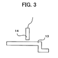
- FIG. 3 is a diagram illustrating the relation between the dog 13 and the proximity switch 14.
- the position of the dog 13 or the mounting position of the proximity switch 14 are adjusted so that, when the crosshead 6a reaches a predetermined position, the dog 13 mounted on the crosshead 6a of the toggle mechanism 6 is sensed by the proximity switch 14.
- the predetermined position at which the proximity switch 14 sensed the dog 13 is set so as to be either a mold touch position where two halves of the mold 5a, 5b contact each other, or a position where the mold halves are opened by a predetermined distance from the mold touch position.
- FIG. 2 is a flow chart showing an algorithm of a belt breakage detection process to be executed by a processor of the controller 15 during opening and closing of the mold.
- Step S1 the processor of the controller 15 determines whether or not the crosshead 6a has reached the set predetermined position based on the position feedback signals from the position/speed detector 12 mounted on the clamping servomotor 8 (Step S2).
- the processor determines that the crosshead 6a has reached the predetermined position based on the position feedback signals, it then determines whether or not a signal indicating sensing of the dog 13 has been inputted from the proximity switch 14 (Step S3).
- the proximity switch 14 senses the dog 13 when the position of the crosshead 6a determined based on the detection by the position/speed detector 12 has reached the predetermined position, and therefore the opening or closing movement of the mold continues as is.
- Step S3 the processor outputs an alarm and stops the movement of the mold.
- the sensing unit that senses the arrival of the crosshead 6a at the predetermined position is comprised of the dog 13 and the proximity switch 14, another equally simple sensing unit such as a limit switch may be used instead.
Landscapes
- Engineering & Computer Science (AREA)
- Manufacturing & Machinery (AREA)
- Mechanical Engineering (AREA)
- Moulds For Moulding Plastics Or The Like (AREA)
- Injection Moulding Of Plastics Or The Like (AREA)
Abstract
In a toggle-type clamping device that is driven by a belt (9) driven by a motor, it is desired to detect securely a break in the belt (9) using a simple and inexpensive construction. A dog (13) is mounted on a crosshead of a toggle mechanism, a proximity switch (14) is mounted on a rear platen, and arrival of the crosshead at a predetermined position is detected. A position detector is mounted on a motor that drives the toggle mechanism via a belt and a ball screw. When arrival of the crosshead at the predetermined position (a mold touch position or a position at which the mold is open a predetermined distance from the mold touch position) is detected by the position detector, if the dog (13) is not detected by the proximity switch (14), the clamping device outputs an alarm as an indication that an abnormality such as a break in the belt (9) has occurred. Simply by adding to a conventional toggle-type clamping device a simple and inexpensive detection unit such as the proximity switch (14), the dog (13), and the like, abnormalities such as belt breakage and the like can be securely detected.
Description
- The present invention relates to a clamping device of an injection molding machine, and more particularly to a mold clamping device for clamping a mold by driving a toggle mechanism by a motor through a belt.
- In injection molding machines, when driving a toggle-type clamping mechanism with a motor, a method that transmits torque of the motor through a belt to the toggle mechanism of a clamping device to drive the clamping device is commonly employed. In addition, a method that detects a position of a movable-side mold driven by the clamping device by a rotation position of the motor that drives the clamping device is also common.
- At the same time, because a large clamping force is required of the clamping device the force transmitted by the belt is also large, and therefore the belt sometimes breaks. A variety of methods have been proposed for detecting such belt breaks and preventing faulty operation of the injection molding machine.
- For example, in a clamping device that transmits motor torque to a crosshead of a toggle mechanism of the clamping device with a timing belt, providing a first pulse generator that detects the rotation of the motor and a second pulse generator that detects movement of the crosshead, and determining that an abnormality has occurred when the difference in the number of pulses measured by the first and second pulse generators exceeds a predetermined range is known (see
JP07-16901A - In addition, mounting on a drive shaft driven by a motor (a first pulley) a first pulse generating means such as a rotary encoder that detects rotations of the drive shaft and having a second pulse generating means composed of a proximity switch that detects proximity of a dog provided on a second pulley driven by the drive shaft through a power transmission belt, providing count-speed converters that obtain the rotation speeds of each pulley from a first and a second pulse width counter that count the number of pulses from a clock pulse generator in a single cycle of pulses generated from the first pulse generator and the second pulse generator and from the counts of the first and second pulse width generators, comparing the rotation speeds of the first and second pulleys, and outputting a malfunction signal whenever the difference between the two speeds meets or exceeds a threshold value is known (see
JP2003-174786A - Further, providing one or more projections in a circumferential direction on a side of a driven pulley to which a motor transmits rotation via a driving pulley and a belt as well as providing a proximity switch that detects the projections and generates ON-OFF signals, and detecting an absence of ON-OFF signals from the proximity switch during motor drive as a belt break is known (see
JP2003-74649A - Further, in an injection molding machine that transmits torque of a motor to a toggle mechanism of a clamping device with a timing belt, storing the torque of the motor during normal operation and determining that there is a break in the timing belt when a torque detected by a torque detection means is smaller than the stored torque by a predetermined amount is known (see
JP06-182845A - However, as methods of detecting a break in the belt that transmits the torque of the motor to the toggle mechanism of the clamping device, of the methods described above the methods taught by
JP07-16901A JP2003-174786A - Moreover, with the method of detecting the rotations of the driven-side pulley taught by
JP2003-74649A JP06-182845A - The present invention provides a mold clamping device of an injection molding machine capable of detecting a break in a belt simply and securely and preventing faulty operation of an injection molding machine.
- A mold clamping device of the present invention comprises: a motor; a toggle mechanism having a crosshead; a transmission mechanism for transmitting an output of the motor to the toggle mechanism through a belt; a position detector for detecting a rotational position of the motor, so that a position of the crosshead of the toggle mechanism is determined based on the detected rotational position of the motor; a sensing unit for sensing an arrival of the crosshead of the toggle mechanism at a predetermined position; and abnormality determining means that determines an abnormality if an arrival of the crosshead at the predetermined position is not sensed by the sensing unit when the position of the crosshead determined based on the detected rotational position of the motor reaches the predetermined position.
- The sensing unit may comprise a proximity switch and a dog. The predetermined position may be set to a mold touch position where mold halves touch with each other or to a position where the mold halves are opened by a predetermined distance from the mold touch position.
- According to the injection molding machine clamping device having the construction described above, simply by adding to a conventional toggle-type clamping device a simple detection unit, abnormalities such as belt breakage and the like can be detected simply, inexpensively and securely.
-
- FIG. 1 is a schematic diagram of a clamping device according to an embodiment of the present invention;
- FIG. 2 is a flow chart illustrating an algorithm of a belt breakage detection process that a processor of a control device of the clamping device according to the embodiment of the present invention executes during opening and closing of a mold; and
- FIG. 3 is a diagram illustrating a dog and a proximity switch of the clamping device according to the embodiment of the present invention.
- FIG. 1 is a schematic diagram of a clamping device according to an embodiment of the present invention. A stationary platen 1 and a
rear platen 2 are coupled to each other by a plurality oftie bars 4. Between the stationary platen 1 and the rear platen 2 amovable platen 3 is disposed so as to be movable along thetie bars 4. In addition, astationary mold half 5a is mounted on the stationary platen 1 and a movable mold 5half b is mounted on themovable platen 3. - Between the
rear platen 2 and the movable platen 3 a toggle mechanism 6 is disposed. A ball nut provided on acrosshead 6a of the toggle mechanism 6 engages aball screw 7 mounted on therear platen 2 so as to be rotatable but unmovable in an axial direction. Abelt 9 is suspended between apulley 10 provided on theball screw 7 and apulley 11 provided on an output shaft of aclamping servomotor 8 used for clamping. Theball screw 7 is driven by the drive of theclamping servomotor 8 via thepulley 11, thebelt 9, and thepulley 10, causing thecrosshead 6a of the toggle mechanism 6 to advance and retreat (that is, to move laterally left and right in FIG. 1) and driving the toggle mechanism 6, which in turn moves themovable platen 3 toward and away from the stationary platen 1, opening/closing and clamping the two halves of themold speed detector 12 such as a pulse encoder or the like that detects a rotation position and a speed of theclamping servomotor 8 is mounted on theclamping servomotor 8, such that the position of thecrosshead 6a and the position of the movable platen 3 (that is, the movable-side mold 5b) can be detected by feedback signals from the position/speed detector 12. - It should be noted that
reference numeral 16 designates an eject mechanism provided on themovable platen 3 for pushing a molded product out of the interior of the mold, which works by driving aneject motor 16a during opening of the mold so as to push an eject pin into the interior of the mold, thus pushing the molded product out of the mold. In addition,reference numeral 17 designates a clamping force adjustment mechanism provided on therear platen 2, which drives a clampingforce adjustment motor 17a that rotates nuts that engage screws mounted on thetie bars 4 through a transmission mechanism so as to change the position of therear platen 2 with respect to thetie bars 4 and thereby adjust the clamping force. Theeject mechanism 16 and the clampingforce adjustment mechanism 17 are not directly related to the present invention and detailed descriptions thereof are therefore omitted. -
Reference numeral 15 designates a controller for controlling the injection molding machine, and as conventionally comprises a processor, memory units such as a ROM, a RAM, etc., an input/output interface, and a motor control circuit that controls the position and speed of the servomotors that drive the movable parts of the injection molding machine. Thecontroller 15 controls the driving of the movable parts of the injection molding machine such as theclamping servomotor 8, theeject motor 16a, and the clampingforce adjustment motor 17a described above. Further, the position/speed detector 12 mounted on theclamping servomotor 8 is connected to thecontroller 15 so that signals from the position/speed detector 12 are fed back to thecontroller 15. - The construction described above is the same construction as that of the conventional toggle-type clamping device, and does not differ from the related art. The distinctive feature of the present invention is the addition of a detection unit to the toggle mechanism 6 side of this type of toggle-type clamping device that detects the arrival of the
crosshead 6a of the toggle mechanism 6 at a predetermined position. Specifically, in the present embodiment, as the detection unit, adog 13 is provided on thecrosshead 6a and aproximity switch 14 that detects thedog 13 when thedog 13 reaches a predetermined position is provided on therear platen 2. Theproximity switch 14 is also connected to thecontroller 15. - FIG. 3 is a diagram illustrating the relation between the
dog 13 and theproximity switch 14. The position of thedog 13 or the mounting position of theproximity switch 14 are adjusted so that, when thecrosshead 6a reaches a predetermined position, thedog 13 mounted on thecrosshead 6a of the toggle mechanism 6 is sensed by theproximity switch 14. The predetermined position at which the proximity switch 14 sensed thedog 13 is set so as to be either a mold touch position where two halves of themold - FIG. 2 is a flow chart showing an algorithm of a belt breakage detection process to be executed by a processor of the
controller 15 during opening and closing of the mold. - When an opening or closing movement of the mold begins (Step S1), the processor of the
controller 15 determines whether or not thecrosshead 6a has reached the set predetermined position based on the position feedback signals from the position/speed detector 12 mounted on the clamping servomotor 8 (Step S2). When the processor determines that thecrosshead 6a has reached the predetermined position based on the position feedback signals, it then determines whether or not a signal indicating sensing of thedog 13 has been inputted from the proximity switch 14 (Step S3). If no abnormality such as breakage of thebelt 9 has occurred, the proximity switch 14 senses thedog 13 when the position of thecrosshead 6a determined based on the detection by the position/speed detector 12 has reached the predetermined position, and therefore the opening or closing movement of the mold continues as is. - By contrast, when it is determined that the
proximity switch 14 has not sensed thedog 13 in Step S3, the processor outputs an alarm and stops the movement of the mold (Step S4). - Thus, as described above, simply by adding a simple mechanism comprised of the
proximity switch 14 and thedog 13 to the conventional toggle-type clamping device, abnormalities such as a break in thebelt 9 and the like can be detected simply, inexpensively and securely by utilizing the position/speed detector 12 or the like mounted on theclamping servomotor 8 of the conventional toggle-type clamping device. - It should be noted that although in the above-described embodiment the sensing unit that senses the arrival of the
crosshead 6a at the predetermined position is comprised of thedog 13 and theproximity switch 14, another equally simple sensing unit such as a limit switch may be used instead.
Claims (3)
- A mold clamping device of an injection molding machine, comprising:a motor;a toggle mechanism having a crosshead;a transmission mechanism for transmitting an output of said motor to said toggle mechanism through a belt;a position detector for detecting a rotational position of said motor, so that a position of the crosshead of said toggle mechanism is determined based on the detected rotational position of the motor;a sensing unit for sensing an arrival of the crosshead of the toggle mechanism at a predetermined position; andabnormality determining means that determines an abnormality if an arrival of the crosshead at the predetermined position is not sensed by said sensing unit when the position of the crosshead determined based on the detected rotational position of the motor reaches the predetermined position.
- A mold clamping device of an injection molding machine according to claim 1, wherein said sensing unit comprises a proximity switch and a dog.
- A mold clamping device of an injection molding machine according to claim 1, wherein the predetermined position is set to a mold touch position where mold halves touch with each other or to a position where the mold halves are opened from the mold touch position by a predetermined distance.
Applications Claiming Priority (1)
| Application Number | Priority Date | Filing Date | Title |
|---|---|---|---|
| JP2006231705A JP2008055617A (en) | 2006-08-29 | 2006-08-29 | Mold clamping device of injection molding machine |
Publications (1)
| Publication Number | Publication Date |
|---|---|
| EP1894701A1 true EP1894701A1 (en) | 2008-03-05 |
Family
ID=38657206
Family Applications (1)
| Application Number | Title | Priority Date | Filing Date |
|---|---|---|---|
| EP07114365A Withdrawn EP1894701A1 (en) | 2006-08-29 | 2007-08-15 | Mold clamping device of injection molding machine |
Country Status (4)
| Country | Link |
|---|---|
| US (1) | US20080057146A1 (en) |
| EP (1) | EP1894701A1 (en) |
| JP (1) | JP2008055617A (en) |
| CN (1) | CN101148085A (en) |
Cited By (1)
| Publication number | Priority date | Publication date | Assignee | Title |
|---|---|---|---|---|
| CN113246423A (en) * | 2021-04-02 | 2021-08-13 | 海天塑机集团有限公司 | Secondary door opening control method for electric door of injection molding machine |
Families Citing this family (12)
| Publication number | Priority date | Publication date | Assignee | Title |
|---|---|---|---|---|
| JP5016707B2 (en) * | 2010-07-27 | 2012-09-05 | 日精樹脂工業株式会社 | Belt monitoring device for injection molding machine |
| TW201228799A (en) * | 2011-01-07 | 2012-07-16 | Acumen Co Ltd | Electrical injection molding machine |
| JP5134110B2 (en) | 2011-05-12 | 2013-01-30 | ファナック株式会社 | Toggle mold clamping device |
| CN103112136A (en) * | 2013-02-20 | 2013-05-22 | 翁学海 | Mode locking device |
| JP6162612B2 (en) * | 2014-01-15 | 2017-07-12 | ファナック株式会社 | Abnormality detection device for movable parts of injection molding machine |
| JP6427369B2 (en) * | 2014-09-16 | 2018-11-21 | 東芝機械株式会社 | Abnormality detection device for power transmission means, molding device and abnormality detection method for power transmission means |
| JP7043321B2 (en) * | 2018-03-30 | 2022-03-29 | 住友重機械工業株式会社 | Injection molding machine |
| JP7294960B2 (en) * | 2019-08-30 | 2023-06-20 | ファナック株式会社 | Injection molding machine |
| CN112092317A (en) * | 2020-08-13 | 2020-12-18 | 宁波长飞亚塑料机械制造有限公司 | A negative relief angle type toggle link mold clamping mechanism |
| CN112318840B (en) * | 2020-10-14 | 2025-08-12 | 宁波创基机械股份有限公司 | Belt mode locking action detection device |
| JP7559640B2 (en) * | 2021-03-23 | 2024-10-02 | Ubeマシナリー株式会社 | Clamping force adjustment method and clamping device |
| CN115456652B (en) * | 2022-09-29 | 2023-06-20 | 广东格林精密部件股份有限公司 | Precise injection molding defective product tracing method based on artificial intelligence |
Citations (4)
| Publication number | Priority date | Publication date | Assignee | Title |
|---|---|---|---|---|
| JPS61233518A (en) * | 1985-04-10 | 1986-10-17 | Mitsubishi Heavy Ind Ltd | Apparatus for changing over injection speed |
| JPH03114805A (en) * | 1989-09-29 | 1991-05-16 | Nissei Plastics Ind Co | Method for detecting position in toggle type mold clamping device |
| JPH0716901A (en) * | 1993-06-30 | 1995-01-20 | Japan Steel Works Ltd:The | Method and apparatus for detecting abnormality in power transmission means of electric injection molding machine |
| US5929583A (en) * | 1998-03-13 | 1999-07-27 | Cincinnati Milacron Inc. | Method and apparatus for detecting aberrant motor operation in a plastics processing machine |
Family Cites Families (9)
| Publication number | Priority date | Publication date | Assignee | Title |
|---|---|---|---|---|
| US5059365A (en) * | 1990-05-17 | 1991-10-22 | Cincinnati Milacron Inc. | Method of setting and maintaining a desired mold clamping force |
| US5362222A (en) * | 1993-08-31 | 1994-11-08 | Cincinnati Milacron Inc. | Injection molding machine having a vector controlled AC drive system |
| US6011376A (en) * | 1998-03-13 | 2000-01-04 | Cincinnati Milacron Inc. | Method and apparatus for injection molding machine control |
| JP3235059B2 (en) * | 1998-12-22 | 2001-12-04 | 住友重機械工業株式会社 | Mold clamping controller |
| JP2001062884A (en) * | 1999-08-31 | 2001-03-13 | Toshiba Mach Co Ltd | Apparatus and method for setting position of movable mold of motor-operated injection molding machine |
| US6419861B1 (en) * | 1999-11-10 | 2002-07-16 | Uniloy Milacron Usa Inc. | Method and apparatus for setting die height |
| JP3910803B2 (en) * | 2001-04-02 | 2007-04-25 | 東芝機械株式会社 | Mold protection method in injection molding machine |
| JP2002326265A (en) * | 2001-04-27 | 2002-11-12 | Toshiba Mach Co Ltd | Method for monitoring mold opening force in motor- operated injection molding machine |
| CA2477149C (en) * | 2002-02-28 | 2012-10-02 | Ube Machinery Corporation, Ltd. | Method for expansion injection molding |
-
2006
- 2006-08-29 JP JP2006231705A patent/JP2008055617A/en active Pending
-
2007
- 2007-08-15 EP EP07114365A patent/EP1894701A1/en not_active Withdrawn
- 2007-08-27 US US11/892,801 patent/US20080057146A1/en not_active Abandoned
- 2007-08-29 CN CNA2007101477944A patent/CN101148085A/en active Pending
Patent Citations (4)
| Publication number | Priority date | Publication date | Assignee | Title |
|---|---|---|---|---|
| JPS61233518A (en) * | 1985-04-10 | 1986-10-17 | Mitsubishi Heavy Ind Ltd | Apparatus for changing over injection speed |
| JPH03114805A (en) * | 1989-09-29 | 1991-05-16 | Nissei Plastics Ind Co | Method for detecting position in toggle type mold clamping device |
| JPH0716901A (en) * | 1993-06-30 | 1995-01-20 | Japan Steel Works Ltd:The | Method and apparatus for detecting abnormality in power transmission means of electric injection molding machine |
| US5929583A (en) * | 1998-03-13 | 1999-07-27 | Cincinnati Milacron Inc. | Method and apparatus for detecting aberrant motor operation in a plastics processing machine |
Cited By (2)
| Publication number | Priority date | Publication date | Assignee | Title |
|---|---|---|---|---|
| CN113246423A (en) * | 2021-04-02 | 2021-08-13 | 海天塑机集团有限公司 | Secondary door opening control method for electric door of injection molding machine |
| CN113246423B (en) * | 2021-04-02 | 2022-05-17 | 海天塑机集团有限公司 | Secondary door opening control method for electric door of injection molding machine |
Also Published As
| Publication number | Publication date |
|---|---|
| JP2008055617A (en) | 2008-03-13 |
| CN101148085A (en) | 2008-03-26 |
| US20080057146A1 (en) | 2008-03-06 |
Similar Documents
| Publication | Publication Date | Title |
|---|---|---|
| US20080057146A1 (en) | Mold clamping device of injection molding machine | |
| US6616872B2 (en) | Method of and apparatus for determining separating force of molded product from mold | |
| JP4568350B2 (en) | Abnormality detection device for injection molding machine | |
| US8651846B2 (en) | Abnormality detection apparatus of an injection molding machine | |
| JP4477546B2 (en) | Molding condition setting method | |
| EP4177692A1 (en) | Management device for power transmission mechanism and management method for power transmission mechanism | |
| JP4077840B2 (en) | Clamping device abnormality detection device | |
| US20110177187A1 (en) | Injection molding machine provided with power transmission mechanism | |
| US5639486A (en) | Control device for an ejector mechanism used in an injection molding machine | |
| EP1958752B1 (en) | Method of indicating an open/close state of a check valve of an injection molding machine | |
| JP2006231749A (en) | Device for detecting abnormality of pressure of injection molding machine | |
| JP3366691B2 (en) | Abnormality detection method of power transmission means of electric injection molding machine | |
| JP2009241425A (en) | Injection molding machine | |
| US7252796B2 (en) | Ejecting load monitoring method for injection molding machine | |
| JP6034741B2 (en) | Injection molding machine that can detect a decrease in clamping force | |
| JP7091345B2 (en) | Signal processing methods for injection molding machines | |
| JP3910052B2 (en) | Abnormality detection device for power transmission means | |
| JP4568261B2 (en) | Abnormality detection device for power transmission means of electric injection molding machine | |
| JP3484629B2 (en) | Self-diagnosis device of injection molding machine | |
| US7132067B2 (en) | Mold-clamping control method for injection molding machine | |
| JP4964313B2 (en) | Molding condition setting method and mold clamping device | |
| CN112318840B (en) | Belt mode locking action detection device | |
| JP2003074649A (en) | Belt breakage detector and electric injection molding machine using the same | |
| JP2010194918A (en) | Drive control method for injection molding machine and drive control device | |
| JP5179993B2 (en) | Injection molding machine equipped with a method for determining the closed state of the backflow prevention valve of the injection molding machine and its discrimination function |
Legal Events
| Date | Code | Title | Description |
|---|---|---|---|
| PUAI | Public reference made under article 153(3) epc to a published international application that has entered the european phase |
Free format text: ORIGINAL CODE: 0009012 |
|
| AK | Designated contracting states |
Kind code of ref document: A1 Designated state(s): AT BE BG CH CY CZ DE DK EE ES FI FR GB GR HU IE IS IT LI LT LU LV MC MT NL PL PT RO SE SI SK TR |
|
| AX | Request for extension of the european patent |
Extension state: AL BA HR MK YU |
|
| 17P | Request for examination filed |
Effective date: 20080328 |
|
| AKX | Designation fees paid |
Designated state(s): DE |
|
| STAA | Information on the status of an ep patent application or granted ep patent |
Free format text: STATUS: THE APPLICATION HAS BEEN WITHDRAWN |
|
| 18W | Application withdrawn |
Effective date: 20090427 |