EP1894700A1 - Mold clamping force detection method - Google Patents
Mold clamping force detection method Download PDFInfo
- Publication number
- EP1894700A1 EP1894700A1 EP06766959A EP06766959A EP1894700A1 EP 1894700 A1 EP1894700 A1 EP 1894700A1 EP 06766959 A EP06766959 A EP 06766959A EP 06766959 A EP06766959 A EP 06766959A EP 1894700 A1 EP1894700 A1 EP 1894700A1
- Authority
- EP
- European Patent Office
- Prior art keywords
- mold
- output
- clamping force
- value
- strain
- Prior art date
- Legal status (The legal status is an assumption and is not a legal conclusion. Google has not performed a legal analysis and makes no representation as to the accuracy of the status listed.)
- Granted
Links
- 238000001514 detection method Methods 0.000 title claims abstract description 152
- 238000000465 moulding Methods 0.000 claims abstract description 14
- 230000005856 abnormality Effects 0.000 claims description 5
- 230000000717 retained effect Effects 0.000 claims description 2
- 230000008859 change Effects 0.000 abstract description 14
- 238000000034 method Methods 0.000 description 22
- 101710170231 Antimicrobial peptide 2 Proteins 0.000 description 15
- 230000008569 process Effects 0.000 description 15
- 238000010586 diagram Methods 0.000 description 14
- 238000006243 chemical reaction Methods 0.000 description 9
- 230000007246 mechanism Effects 0.000 description 9
- 230000032683 aging Effects 0.000 description 8
- 238000001746 injection moulding Methods 0.000 description 8
- 101710170230 Antimicrobial peptide 1 Proteins 0.000 description 5
- 230000003321 amplification Effects 0.000 description 4
- 238000003199 nucleic acid amplification method Methods 0.000 description 4
- 230000002159 abnormal effect Effects 0.000 description 3
- 230000008602 contraction Effects 0.000 description 2
- 238000012986 modification Methods 0.000 description 2
- 230000004048 modification Effects 0.000 description 2
- 230000035882 stress Effects 0.000 description 2
- 230000000694 effects Effects 0.000 description 1
- 238000005516 engineering process Methods 0.000 description 1
- 230000007774 longterm Effects 0.000 description 1
Images






Classifications
-
- B—PERFORMING OPERATIONS; TRANSPORTING
- B29—WORKING OF PLASTICS; WORKING OF SUBSTANCES IN A PLASTIC STATE IN GENERAL
- B29C—SHAPING OR JOINING OF PLASTICS; SHAPING OF MATERIAL IN A PLASTIC STATE, NOT OTHERWISE PROVIDED FOR; AFTER-TREATMENT OF THE SHAPED PRODUCTS, e.g. REPAIRING
- B29C45/00—Injection moulding, i.e. forcing the required volume of moulding material through a nozzle into a closed mould; Apparatus therefor
- B29C45/17—Component parts, details or accessories; Auxiliary operations
- B29C45/64—Mould opening, closing or clamping devices
-
- B—PERFORMING OPERATIONS; TRANSPORTING
- B22—CASTING; POWDER METALLURGY
- B22D—CASTING OF METALS; CASTING OF OTHER SUBSTANCES BY THE SAME PROCESSES OR DEVICES
- B22D17/00—Pressure die casting or injection die casting, i.e. casting in which the metal is forced into a mould under high pressure
- B22D17/20—Accessories: Details
- B22D17/26—Mechanisms or devices for locking or opening dies
-
- B—PERFORMING OPERATIONS; TRANSPORTING
- B22—CASTING; POWDER METALLURGY
- B22D—CASTING OF METALS; CASTING OF OTHER SUBSTANCES BY THE SAME PROCESSES OR DEVICES
- B22D17/00—Pressure die casting or injection die casting, i.e. casting in which the metal is forced into a mould under high pressure
- B22D17/20—Accessories: Details
- B22D17/32—Controlling equipment
-
- B—PERFORMING OPERATIONS; TRANSPORTING
- B29—WORKING OF PLASTICS; WORKING OF SUBSTANCES IN A PLASTIC STATE IN GENERAL
- B29C—SHAPING OR JOINING OF PLASTICS; SHAPING OF MATERIAL IN A PLASTIC STATE, NOT OTHERWISE PROVIDED FOR; AFTER-TREATMENT OF THE SHAPED PRODUCTS, e.g. REPAIRING
- B29C45/00—Injection moulding, i.e. forcing the required volume of moulding material through a nozzle into a closed mould; Apparatus therefor
- B29C45/17—Component parts, details or accessories; Auxiliary operations
- B29C45/76—Measuring, controlling or regulating
-
- B—PERFORMING OPERATIONS; TRANSPORTING
- B29—WORKING OF PLASTICS; WORKING OF SUBSTANCES IN A PLASTIC STATE IN GENERAL
- B29C—SHAPING OR JOINING OF PLASTICS; SHAPING OF MATERIAL IN A PLASTIC STATE, NOT OTHERWISE PROVIDED FOR; AFTER-TREATMENT OF THE SHAPED PRODUCTS, e.g. REPAIRING
- B29C45/00—Injection moulding, i.e. forcing the required volume of moulding material through a nozzle into a closed mould; Apparatus therefor
- B29C45/17—Component parts, details or accessories; Auxiliary operations
- B29C45/76—Measuring, controlling or regulating
- B29C45/7653—Measuring, controlling or regulating mould clamping forces
-
- B—PERFORMING OPERATIONS; TRANSPORTING
- B29—WORKING OF PLASTICS; WORKING OF SUBSTANCES IN A PLASTIC STATE IN GENERAL
- B29C—SHAPING OR JOINING OF PLASTICS; SHAPING OF MATERIAL IN A PLASTIC STATE, NOT OTHERWISE PROVIDED FOR; AFTER-TREATMENT OF THE SHAPED PRODUCTS, e.g. REPAIRING
- B29C2945/00—Indexing scheme relating to injection moulding, i.e. forcing the required volume of moulding material through a nozzle into a closed mould
- B29C2945/76—Measuring, controlling or regulating
- B29C2945/76177—Location of measurement
- B29C2945/76224—Closure or clamping unit
- B29C2945/76234—Closure or clamping unit tie-bars
-
- B—PERFORMING OPERATIONS; TRANSPORTING
- B29—WORKING OF PLASTICS; WORKING OF SUBSTANCES IN A PLASTIC STATE IN GENERAL
- B29C—SHAPING OR JOINING OF PLASTICS; SHAPING OF MATERIAL IN A PLASTIC STATE, NOT OTHERWISE PROVIDED FOR; AFTER-TREATMENT OF THE SHAPED PRODUCTS, e.g. REPAIRING
- B29C2945/00—Indexing scheme relating to injection moulding, i.e. forcing the required volume of moulding material through a nozzle into a closed mould
- B29C2945/76—Measuring, controlling or regulating
- B29C2945/76451—Measurement means
- B29C2945/76481—Strain gauges
Definitions
- the present invention relates to mold-clamping force detection methods and, more particularly, to a mold-clamping force detection method that detects a mold-clamping force using a strain gauge which measures a strain of a tie bar of a mold-clamping apparatus of a molding machine.
- a method of measuring a strain (elongation) of a tie bar of a mold-clamping apparatus and converting the measured strain into a mold-clamping force.
- a tensile stress proportional to a mold-clamping force is generated in a tie bar.
- the mold-clamping force actually applied to the mold can be acquired by detecting the strain (elongation) of the tie bar generated by the tensile stress.
- a strain gauge is used as means for detecting a strain of a rod-like member such as a tie bar (for example, refer to Patent Document 1).
- a strain gauge is constituted by a bridge circuit consisting of a plurality of resistors. At least one of the resistors is attached to an object to be measured (tie bar) so as to be distorted together with the object to be measured.
- the strain gauge is a strain detection apparatus which measures a strain based on a change in an output voltage caused by a change in a resistance corresponding to such a strain.
- Patent Document Japanese Laid-Open Patent Application No. 2002-103402
- a drift occurs in an output voltage from the strain detection apparatus due to aging of a resistor attached to an object to be measured or aging of an attaching means. If the drift occurs in the output voltage, an error occurs in a clamping force acquired by conversion of the output voltage.
- the strain detection apparatus for detecting a mold-clamping force of a conventional injection molding machine there has been taken no measures for the detection error of a mold-clamping force due to the drift in the output voltage since less accuracy has been required in detecting a mold-clamping force.
- a more specific object of the present invention is to provide a mold-clamping force detection method which can detect a mold-clamping force with good accuracy by correcting a drift in an output from a strain detection apparatus due to aging.
- a mold-clamping force detection method for detecting a mold-clamping force based on an output from at least one strain detection apparatus provided to a mold-clamping apparatus of a molding machine, comprising: detecting a first output value output from the strain detection apparatus when the mold-clamping apparatus is unloaded; correcting a second output value output from the strain detection apparatus based on the first output value when a mold-clamping force is generated by the mold-clamping apparatus; and acquiring the mold-clamping force based on the corrected second output value.
- a plurality of the strain detection apparatuses may be provided to the mold-clamping force of the molding machine, and acquiring the second output value from the first output value output from each of the strain detection apparatuses, and acquiring the mold-clamping force based on a sum of the second output values.
- the correction of the output value may be performed using a digital value which is an output from the strain detection apparatus being converted into a digital value, or the strain detection apparatus may comprise a strain gauge, and the correction of the second output value may be performed by changing a reference voltage supplied to a comparison amplifier circuit of the strain gauge based on the first output value.
- an output voltage of the comparison amplifier circuit may be converted into a digital value and retained so as to generate the reference voltage by converting the digital value into an analog value. It is preferable that the comparison amplifier circuit includes at least two comparison amplifiers connected in series.
- a comparison may be made between output values based on at least two of the strain detection apparatuses so as to determine an abnormality when a result of the comparison is greater than a predetermined value.
- the present invention since a changed part of the output caused by aging of the strain detection apparatus is reflected in the output, the drift in the output due to the aging of the strain detection apparatus is corrected and an actual strain can be detected accurately. Thereby, a mold-clamping force of a mold of an injection molding machine can be detected accurately, and an optimum molding condition can be set efficiently based on the accurate detection value of the mold-clamping force.
- FIG. 1 A description will be given briefly below, with reference to FIG. 1 , of a mold-clamping apparatus of an injection molding machine as an apparatus to which a strain detection apparatus according to the present invention is applicable.
- FIG. 1 is a side view of a mold-clamping apparatus of an injection molding machine to which a strain detection apparatus according to the present invention is attached.
- the mold-clamping apparatus shown in FIG. 1 comprises a mold thickness adjustment apparatus 10 and a mold-clamping mechanism 20.
- the mold-clamping mechanism 20 is a toggle type mold-clamping mechanism, which comprises a stationary platen 21, tie bars 22, a movable platen 23, an arm 24, a toggle support 25, a servo motor 26 for mold-clamping, a ball screw 27 and a crosshead 28.
- a stationary mold (not shown in the figure) is attached to the stationary platen 21, and a movable mold (not shown in the figure) is attached to the movable platen 23. Opening and closing operation and mold-clamping operation of the mold is performed by moving the movable mold with respect to the stationary mold by moving the movable platen 23 along the tie bars 22.
- a rotational motion of the servo motor 26 is converted into a linear motion by the ball screw 27 and is transmitted to a toggle mechanism (consisting of the crosshead 28, a toggle levers 29a and 29b and the arm 24)connected to the ball screw 27.
- the toggle mechanism is connected to the movable platen 23 so that the movable platen 23 is moved forward and backward by the linear motion of the toggle mechanism.
- a strain detection apparatus 30 as a mold-clamping force detection apparatus is provided to one of the tie bars 22 so as to detect a mold-clamping force by an output of the strain detection apparatus 30.
- the strain detection apparatus 30 detects an elongation of the tie bar 22 using a strain gauge.
- the strain gauge is applied to the tie bar 22, or attached to the tie bar 22 by being pressed against the tie bar 22 by a fixing jig so as to be elongated and contacted together with the tie bar 22.
- the strain gauge comprises resistance wires, and is configured to detect elongation and contraction based on an output voltage caused by a change in the resistance value due to the elongation and contraction of the resistance wire when a voltage is applied to the strain gauge.
- the output voltage from the strain detection apparatus 30 is supplied to a control unit 40 provided, for example, in the injection molding machine.
- the control unit 40 converts the output voltage supplied from the strain detection apparatus 30 (strain gauge) so as to acquire a mold-clamping force.
- the acquired mold-clamping force is used for checking or setting molding conditions.
- the strain gauge used in the above-mentioned strain detection apparatus 30 is a detection circuit that detects a change in a resistance value using a known bridge circuit.
- the strain gauge forms a bridge circuit by a combination with a plurality of resistance wires so as to amplify a difference between an output voltage from a predetermined position of the bridge circuit and a reference voltage and output as a voltage signal.
- the circuit is configured so that the reference voltage is a ground potential (0 volt).
- the bridge circuit is configured output 0 volt.
- the resistance values in the bridge circuit are off-balance and it is configured so that a voltage proportional to the change in the resistance values is output.
- the resistance values of the resistance wires constituting the bridge circuit change although they are small. If there is such a change in the resistance values due to such aging, the output voltage form the bridge circuit, which has been set to 0 volt, becomes not equal to 0 volt, and a voltage (for example, 10 millivolts) proportional to the change in the resistance values due to the aging is output.
- the change in the output voltage is referred to as a drift. That is, although the output voltage is set to 0 volt initially in a state where no strain is generated in the tie bar (when there is no load), the output voltage may be drifted when a certain time has passed and becomes equal to 10 millivolts. Thus, a voltage that is a result that 10 millivolts is always added to the voltage generated due to an actual strain (elongation) of the tie bar is output.
- the strain (elongation) of the tie bar is a value acquired by converting the output voltage, and is turn to a different value from an actual strain (elongation) by a voltage drift, which results in generation of an error in detection of a strain.
- a correction is made by canceling a voltage value corresponding to a drift by subtracting the above-mentioned drift in the output voltage at no load from an actual output voltage value.
- This correction includes a soft reset and a hard reset.
- the soft reset is a correction method in which an analog/digital conversion circuit, which converts an output voltage output from the bridge circuit through an amplifier (AMP) so as to perform the cancellation by adding or subtracting a digital value corresponding to a voltage drift to or from a digital value of an output voltage acquired by the digital conversion.
- the soft reset is a method of correction by processing data representing the output voltage according to software.
- the hard reset is a correction method in which a circuit for changing a reference voltage supplied to a comparison amplifier generating the output voltage by a part corresponding to the drift voltage so as to cancel the voltage drift according to hardware (circuit).
- the present invention aims to eliminate influences of the voltage drift, and the above-mentioned soft reset and hard reset are examples thereof and either one can be used, and variations and modifications may be made within the scope of the present invention.
- step S1 an operating state of the mold-clamping apparatus is checked so as to determine whether or not the movable mold is at the maximum mold-open position.
- the maximum mold-open position is a position where the movable mold is farthest from the stationary mold, that is, a position where the movable platen 23 is moved backward at maximum and stopped. There is no clamping-force generated at the maximum mold-open position, and there is no strain (elongation) generated in the tie bars 22.
- step S2 the process proceeds to step S2 to detect an output voltage from the strain detection apparatus 30. Since the movable mold is stopped at the maximum mold-open position, under normal circumstances, the output voltage of the strain detection apparatus 30 is 0 volt and the detection value is 0. However, if there is a change with age in the strain detection apparatus 30, a drift is generated and the output voltage is not equal to 0 volt. Thus, also the detection value is not zero.
- the detection value is a digitized output voltage value in the above-mentioned soft reset, and means a value of the output voltage output from the comparison amplifier in the hard reset.
- step S3 it is determined whether or not the detection value is equal to or greater than a predetermined value.
- the detection value is equal to or greater than the predetermined value, it proceeds to step S4 to set the detection value as an offset value.
- the predetermined value is a threshold value for judging whether or not it is necessary to correct the detection error due to the drift. That is, in the case where the detection value is equal to or greater than the predetermined value, it is assumed that the detection error is not at a negligible degree, and setting is made so that a value which is obtained by subtracting the offset value from the detection value is set to a value for converting into a mold-clamping force.
- the mold-clamping force is calculated based on a value, which is obtained by subtracting the offset value from the detection value at the time of mold-clamping, in the process of actually detecting the mold-clamping force after the correction process. It should be noted that the initial value of the offset value is set to 0.
- the detection value at the time of mold-clamping is a digital value of the output voltage in the soft reset
- the offset value is a digital value of the drift voltage at the maximum mold-open position.
- the detection value at the time of mold-clamping is the output voltage of the strain gauge itself
- the offset value is the drift voltage itself.
- step S5 If the setting to set the value obtained by subtracting the offset value from the detection value is completed in step S5, the process at this time is ended. Additionally, if it is judged in step S1 that the movable mold is not at the maximum mold-open position and if it is determined in step S3 that the detection value is not equal to or greater than the predetermined value, the correction in step S4 is not performed, and the process is ended after proceeding to step S5.
- the movable platen 23 is not limited to this, and may be a position where there are no mold-closing force and no mold-clamping force generated (that is, a state where the mold is open) and the movable platen 23 is not moving and is stopped. That is, a voltage drift is detectable if the movable platen 23 is stopped at a position where the tie bars 22 are in an unloaded state.
- the output voltage value (a first output value) from the strain detection apparatus is detected when the mold-clamping apparatus is unloaded, and the output voltage value (a second output value) output from the strain detection apparatus when a mold-clamping force is generated by the mold-clamping apparatus is corrected based on the first output value, and the mold-clamping force is acquired based on the corrected second output value.
- FIG. 3 is a block circuit diagram of the strain detection apparatus 30 constituted to perform the software reset.
- a strain gauge 50 has a well-known structure, and a description thereof will be omitted.
- an output voltage from the strain gauge 50 is supplied to a digital processing part 60.
- the digital processing part 60 converts the analog voltage signal from the strain gauge 50 into a digital voltage signal by an analog/digital conversion circuit 62.
- the analog/digital conversion circuit 62 converts the output voltage of the strain gauge 50 into a digital value of 5000 when it is 0.5 volt and a digital value of 10000 when it is 1 volt.
- the analog/digital conversion part 60 comprises a reset processing circuit 64 which performs a process of correcting the above-mentioned voltage drift shown in FIG. 2 (in this case, the soft reset).
- the reset processing circuit 64 performs the process in FIG. 2 , when a reset signal RESET is input.
- the output voltage at the maximum mold-open position is converted into a digital value by the analog/digital conversion part 62. If the output voltage (corresponding to a voltage drift) at the maximum mold-open position is 10 millivolts, the 10 millivolts is converted into a digital value 100. Then, the digital value 100 is memorized as the offset value in the above-mentioned step S4.
- the above-mentioned digital processing part 60 may be provided to the strain detection apparatus 30 or the control unit 40 of the molding machine.
- FIG. 4 is a block circuit diagram of the strain detection apparatus 30 constituted to perform the hard reset.
- the strain gauge 50 has a well-known structure and a description thereof will be omitted.
- the output voltage from the strain gauge 50 is sent to the control unit 40 of the molding machine as a voltage signal as it is.
- the correction of a voltage drift is performed by a correction circuit 70.
- the correction circuit 70 comprises an output voltage detection circuit 72, which detects the output voltage from the strain gauge 50, and a reference voltage generation circuit 74, which generates a reference voltage V_REF supplied to an amplifier of the strain gauge.
- a reset signal RESET is input to the output voltage detection circuit 72
- the output voltage detection circuit 72 detects the output voltage from the strain gauge 50 and supplied the detected output voltage to the reference voltage generation circuit 74. This output voltage corresponds to the voltage drift.
- the reference voltage generation circuit 74 compares the supplied output voltage with a predetermined voltage and, if it is equal to or greater than the predetermined voltage, memorizes this voltage value as an offset value.
- the reference voltage generation circuit 74 When detecting a mold-clamping force at a next time, the reference voltage generation circuit 74 generates a voltage equal to a difference between the memorized voltage value and 0 volt and supplies it to the amplifier of the strain gauge 50 as a reference voltage V_REF. Therefore, since the amplifier of the strain gauge 50 outputs a voltage based on the reference voltage of which part corresponding to a voltage drift is previously adjusted, the output voltage from the strain detection apparatus 30 is equal to the output voltage of which part corresponding to the voltage drift is corrected, and, if this output voltage is supplied to the control unit 40 of the molding machine as it is, the control unit 40 can acquire the actual mold-clamping force which does not contain the part corresponding to the drift voltage.
- the output voltage of a bridge circuit BRIDGE is amplified by a comparison amplifier (differential amplifier) AMP as mentioned above so as to be a strain detection signal. Since the output voltage from the bridge circuit BRIDGE is small, it is necessary to set the amplification factor of the AMP, for example, 100 times. However, it is difficult for a single AMP to achieve 100 times, and, for example, it is necessary to make a structure to amplify by two stages as shown in FIG. 5 .
- FIG. 5 is a diagram showing a circuit structure in which a hard reset circuit according to the present invention is incorporated into an amplification circuit of a strain gauge.
- the amplification circuit of the strain gauge shown in FIG. 5 has a two-stage amplification structure having an AMP1 and an AMP2, and is configured to perform the above-mentioned hard reset with respect to the AMP2.
- the output voltage from the bridge circuit BRIDGE is first amplified to some extent by the AMP1. Then, the output of the AMP1 is again amplified by the AMP2, and is made into the output signal (strain detection signal) VOUT from the strain gauge.
- an auto-zero part is connected to the output line of the AMP2 through a changeover switch SW.
- the auto-zero part is a circuit which performs the above-mentioned hard reset, and comprises an analog/digital converter A/D, a control element CONTROLLER and a digital/analog converter D/A.
- a reference voltage V_REF is output from the auto-zero part, and is supplied to the AMP2. This reference voltage V_REF serves as a correction signal for correcting a part corresponding to a voltage drift in the output voltage of the bridge circuit BRIDGE by the AMP2.
- the changeover switch SW is connected to a grounding side so that the grounding potential is supplied to the auto-zero part and the grounding potential is set to the reference voltage V_REF of the AMP2 as it is and is supplied to the AMP2.
- a reset signal RESET is input to the control element CONTROLLER. Then, the control element CONTROLLER changes the changeover switch SW to the VOUT side. Thereby, the output voltage VOUT of the AMP2 is supplied to the auto-zero part.
- the output voltage VOUT supplied to the auto-zero part is digital-converted by the analog/digital converter A/D so as to be a digital value and is supplied to the control element CONTROLLER.
- the control element CONTROLLER retains the digital value of the output voltage VOUT, and inputs the digital value to the digital/analog converter D/A.
- the digital/analog converter D/A converts the input digital value to an analog value. That is, the output voltage of the AMP2 input to the analog/digital converter A/D is reproduced. This reproduced voltage is the reference voltage V_REF, and is supplied to the reference voltage input terminal of the AMP2.
- the reset signal RESET is input to the control element CONTROLLER, the output voltage from the AMP2 at that time is set as the reference voltage V_REF, and is supplied to the AMP2.
- the control element CONTROLLER retains the digital value of the reference voltage V_REF, and, thereafter, supplies the reference voltage V_REF to the AMP2 continuously.
- the mold-clamping force can be obtained by detecting a force applied to one of the tie bars 22 and quadrupling the detected value.
- the detection error caused by variation between the tie bars 22 can be reduced or eliminated by attaching the strain detection apparatus 30 to each of a plurality of tie bars 22 and calculating a mold-clamping force base on a sum of outputs of the strain detection apparatuses 30.
- FIG. 6 is an illustration showing a case where the strain detection apparatus 30 is provided to each of two tie bars 22 on a diagonal line from among the four tie bars 22. It should be noted that FIG. 6 is an illustration of the stationary platen 21 viewed from the movable platen 23 side in FIG. 1 , and each tie bar 22 is shown as a cross section. As mentioned above, a mold-clamping force can be calculated by acquiring forces applied to the two tie bars 22 on a diagonal line and doubling the sum of these.
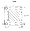
- FIG. 7 is an illustration showing a case where the strain detection apparatus 30 is provided to each of the four tie bars 22.
- a mold-clamping force can be calculated by acquiring forces applied to all tie bars 22 and acquiring a sum of those.
- variation between forces applied to the tie bars 22 does not give an influence to the acquired mold-clamping force, which can obtain an accurate mold-clamping force.
- an output sum may be acquired by inputting the outputs of amplifiers AMP1 through AMP4 of the strain detection apparatuses 30 and the output sum may be converted by an analog/digital converter A/D.
- the outputs from the plurality of strain detection apparatuses 30 are summed in the analog state, and the sum is converted into a digital signal.
- the outputs from the plurality of strain detection apparatuses 30 are converted into digital values individually, and the sum is calculated in digital values.
- the outputs of all strain detection apparatuses 30 may be digital-converted by a single analog/digital converter A/D by using a multiplexer ML.
- the DATA1 through DATA4 are detected values at times shifted by 1 millisecond from each other, and, thus, they are not detected values of a plurality of tie bars at the same time.
- the sum DATA of the DATA1 through DATA4 is assumed to be obtained at a middle time of the times when the DATA1 through the DATA4 are obtained.
- the DATA1 through DATA4 are output for every 1 millisecond, since it takes 3 milliseconds from the time when the DATA1 is obtained to the time when the DAAT4 is obtained, it is supposed that the sum DATA is obtained at a time, as a middle time, when 1.5 milliseconds has passed from the time when the ADTA1 was obtained. Or, it is supposed that the sum DATA is obtained at the time when the DATA1 is obtained so that the sum DATA may be obtained after subtracting a predetermined value from the values of DATA2 through DATA4.
- FIG. 11 is a block circuit diagram of an example in which the structure of the soft reset shown in FIG. 3 is applied to the structure in which the strain detection apparatus 30 is provided to each of the four tie bars.
- the output VOUT of a digital value output from the digital processing circuit 60 of each strain detection apparatus 30 is input to the control unit 40, and a mold-clamping force is acquired by operating a sum of those in the control unit 40. It should be noted that the control unit 40 operates the sum of the outputs of the four strain detection apparatuses 30 at the same time.
- the correction of the voltage drift is performed in the same manner as the process shown in FIG. 2 . That is, when it is determined that the movable platen is at the maximum mold-open position, the process of step S2 to S5 is performed in each strain detection apparatus 30 so as to perform a process of canceling a part corresponding to the voltage drift.
- the voltage drift is generated individually in each strain detection apparatus 30, and the same voltage drift does not always occur in all strain detection apparatuses 30. Accordingly, it is preferable to perform the correction of the voltage drift in each strain detection apparatus 30.
- the structure of the hard reset shown in FIG. 4 may be applied to the structure in which the strain detection apparatus 30 is provided to each of the four tie bars. This structure is the same as the structure shown in FIG. 11 , and a description thereof will be omitted.
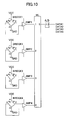
- FIG. 12 is a block circuit diagram of an example in which the structure of the hard reset shown in FIG. 5 is applied to the structure in which the strain detection apparatus 30 is provided to each of the four tie bars.
- the output VOUT of an analog value output from the amplifier AMP2 of each strain detection apparatus 30 is supplied to the multiplexer ML.
- the multiplexer ML sequentially switches the outputs VOUT for every 1 millisecond, and outputs them to the analog/digital converter A/D.
- the correction of the voltage drift is performed in the same manner as the process shown in FIG. 2 in each strain detection apparatus 30.
- an analog/digital converter A/D may by provided to each of the strain detection apparatuses 30 provided to the respective four tie bars.
- the digital value DATA output from each analog/digital converter A/D is input to the control unit 40.
- FIG. 13 is a diagram showing a difference, as a third detection value, between the detection values detected by two strain detection apparatuses 30 attached to the tie bars on a diagonal line as shown in FIG. 6 .
- a solid line indicates the third output value, which is a difference between the detection values of the two strain detection apparatuses 30 when a mold-clamping force is applied to the tie bars in a normal state.
- the difference between the detection values is a small value, and variation between the tie bars is small, and it is judged that a . mold-clamping force is applied to the mold in a well-balanced manner.
- a single-dashed chain line indicates the third output value when a mold-clamping force is applied in an abnormal state. Since the mold-clamping force starts to increase from a mold-touch position and the mold-clamping force becomes constant after the mold-clamping is completed, the third output value as a comparison value increases from the mold-touch position and becomes constant after the completion of the mold-clamping. However, unless the mold-clamping force is applied to the mold in a well-balanced manner, the third detection valued is a very large value as compared to that of the normal state. In this case, it can be judged that the mold-clamping apparatus is in an abnormal state, such as a bad attachment state of the mold or breakage of a tie bar.
- the third output value exceeds the threshold value, it can be judged that an abnormality occurs and the operation of the mold-clamping apparatus may be stopped or an operator is caused to recognize a failure earlier by announcing generation of an abnormality to the operator by generation of an abnormality alarm.
- strain detection apparatus 30 may be provided to not two but all the tie bars. Further, a more accurate judgment can be made by using an integral value.
- the present invention is applicable to a molding machine that detects a mold-clamping force by using a stain gauge for measuring a strain of a tie bar of a mold-clamping apparatus.
Landscapes
- Engineering & Computer Science (AREA)
- Mechanical Engineering (AREA)
- Manufacturing & Machinery (AREA)
- Injection Moulding Of Plastics Or The Like (AREA)
- Moulds For Moulding Plastics Or The Like (AREA)
Abstract
Description
- The present invention relates to mold-clamping force detection methods and, more particularly, to a mold-clamping force detection method that detects a mold-clamping force using a strain gauge which measures a strain of a tie bar of a mold-clamping apparatus of a molding machine.
- For example, as means for detecting a mold-clamping force in a mold of an injection molding machine, there is suggested a method of measuring a strain (elongation) of a tie bar of a mold-clamping apparatus and converting the measured strain into a mold-clamping force. A tensile stress proportional to a mold-clamping force is generated in a tie bar. The mold-clamping force actually applied to the mold can be acquired by detecting the strain (elongation) of the tie bar generated by the tensile stress.
- Generally, a strain gauge is used as means for detecting a strain of a rod-like member such as a tie bar (for example, refer to Patent Document 1). A strain gauge is constituted by a bridge circuit consisting of a plurality of resistors. At least one of the resistors is attached to an object to be measured (tie bar) so as to be distorted together with the object to be measured. The strain gauge is a strain detection apparatus which measures a strain based on a change in an output voltage caused by a change in a resistance corresponding to such a strain.
- Patent Document:
Japanese Laid-Open Patent Application No. 2002-103402 - In a strain detection apparatus using a strain gauge, a drift occurs in an output voltage from the strain detection apparatus due to aging of a resistor attached to an object to be measured or aging of an attaching means. If the drift occurs in the output voltage, an error occurs in a clamping force acquired by conversion of the output voltage. With the strain detection apparatus for detecting a mold-clamping force of a conventional injection molding machine, there has been taken no measures for the detection error of a mold-clamping force due to the drift in the output voltage since less accuracy has been required in detecting a mold-clamping force.
- However, with progress in an injection molding technology, a demand for improving a quality of a mold product by detecting a mold-clamping force precisely and reflecting it in molding conditions has been increasing. In order to detect a mold-clamping force with a sufficient accuracy, it is necessary to correct a drift in an output voltage due to the above-mentioned aging.
- It is a general object of the present invention to provide an improved and useful mold-clamping force detection method in which the above-mentioned problems are eliminated.
- A more specific object of the present invention is to provide a mold-clamping force detection method which can detect a mold-clamping force with good accuracy by correcting a drift in an output from a strain detection apparatus due to aging.
- In order to achieve the above-mentioned objects, there is provided according to the present invention a mold-clamping force detection method for detecting a mold-clamping force based on an output from at least one strain detection apparatus provided to a mold-clamping apparatus of a molding machine, comprising: detecting a first output value output from the strain detection apparatus when the mold-clamping apparatus is unloaded; correcting a second output value output from the strain detection apparatus based on the first output value when a mold-clamping force is generated by the mold-clamping apparatus; and acquiring the mold-clamping force based on the corrected second output value.
- In the above-mentioned invention, a plurality of the strain detection apparatuses may be provided to the mold-clamping force of the molding machine, and acquiring the second output value from the first output value output from each of the strain detection apparatuses, and acquiring the mold-clamping force based on a sum of the second output values.
- In the above-mentioned mold-clamping force detection method, it is preferable to detect the first output value when the mold-clamping apparatus is in a maximum mold-open state. Additionally, the correction of the output value may be performed using a digital value which is an output from the strain detection apparatus being converted into a digital value, or the strain detection apparatus may comprise a strain gauge, and the correction of the second output value may be performed by changing a reference voltage supplied to a comparison amplifier circuit of the strain gauge based on the first output value.
- Additionally, in the above-mentioned mold-clamping force detection method, an output voltage of the comparison amplifier circuit may be converted into a digital value and retained so as to generate the reference voltage by converting the digital value into an analog value. It is preferable that the comparison amplifier circuit includes at least two comparison amplifiers connected in series.
- Further, in the above-mentioned mold-clamping force detection method, a comparison may be made between output values based on at least two of the strain detection apparatuses so as to determine an abnormality when a result of the comparison is greater than a predetermined value.
- According to the present invention, since a changed part of the output caused by aging of the strain detection apparatus is reflected in the output, the drift in the output due to the aging of the strain detection apparatus is corrected and an actual strain can be detected accurately. Thereby, a mold-clamping force of a mold of an injection molding machine can be detected accurately, and an optimum molding condition can be set efficiently based on the accurate detection value of the mold-clamping force.
- Other objects, features and advantages of the present invention will become more apparent from the following detailed description when read in conjunction with the accompanying drawings.
-
- [
FIG. 1 ] is a side view of a mold-clamping apparatus of an injection molding machine to which a strain detection method according to the present invention is applied. - [
FIG. 2 ] is a flowchart of a process of correcting a voltage drift in a clamping force detection method according to the present invention. - [
FIG. 3 ] is a block circuit diagram of a strain detection apparatus constituted to perform a soft reset. - [
FIG. 4 ] is a block circuit diagram of a strain detection apparatus constituted to perform a hard reset. - [
FIG. 5 ] is a circuit diagram of a specific example of a strain detection apparatus configured to perform a hard reset. - [
FIG. 6 ] is an illustration showing a case where a strain detection apparatus is provided to each of two tie bars on a diagonal line from among four tie bars. - [
FIG. 7 ] is an illustration showing a case where a strain detection apparatus is provided to each of four tie bars. - [
FIG. 8 ] is a block circuit diagram showing an example of acquiring a mold-clamping force based on a sum of analog outputs from strain detection apparatuses provided to four tie bars. - [
FIG. 9 ] is a block circuit diagram showing an example of acquiring a mold-clamping force based on a sum of digital outputs from strain detection apparatuses provided to four tie bars. - [
FIG. 10 ] is a block circuit diagram showing an example of acquiring a mold-clamping force based on a sum of analog outputs by outputting the analog outputs from strain detection apparatuses provided to four tie bars through a multiplexer and performing a digital conversion thereon. - [
FIG. 11 ] is a block circuit diagram of an example in which a structure of the soft reset shown inFIG. 3 is applied to a structure in which a strain detection apparatus is provided to each of four tie bars. - [
FIG. 12 ] is a block circuit diagram of an example in which a structure of the hard reset shown inFIG. 5 is applied to a structure in which a strain detection apparatus is provided to each of four tie bars. - [
FIG. 13 ] is an illustration showing as a third output value a difference between detection values detected by two strain detection apparatuses attached to tie bars on a diagonal line. -
- 20
- mold-clamping mechanism
- 21
- stationary platen
- 22
- tie bar
- 23
- movable platen
- 30
- strain detection apparatus
- 40
- control apparatus
- 50
- stain gauge
- 60
- digital processing part
- 62
- analog/digital conversion circuit
- 64
- reset processing circuit
- 70
- correction circuit
- 72
- output voltage detection circuit
- 74
- reference voltage generation circuit
- A description will be given briefly below, with reference to
FIG. 1 , of a mold-clamping apparatus of an injection molding machine as an apparatus to which a strain detection apparatus according to the present invention is applicable. -
FIG. 1 is a side view of a mold-clamping apparatus of an injection molding machine to which a strain detection apparatus according to the present invention is attached. The mold-clamping apparatus shown inFIG. 1 comprises a moldthickness adjustment apparatus 10 and a mold-clampingmechanism 20. The mold-clampingmechanism 20 is a toggle type mold-clamping mechanism, which comprises astationary platen 21, tie bars 22, amovable platen 23, anarm 24, atoggle support 25, aservo motor 26 for mold-clamping, aball screw 27 and acrosshead 28. - A stationary mold (not shown in the figure) is attached to the
stationary platen 21, and a movable mold (not shown in the figure) is attached to themovable platen 23. Opening and closing operation and mold-clamping operation of the mold is performed by moving the movable mold with respect to the stationary mold by moving themovable platen 23 along the tie bars 22. - In the mold-clamping
mechanism 20, a rotational motion of theservo motor 26 is converted into a linear motion by theball screw 27 and is transmitted to a toggle mechanism (consisting of thecrosshead 28, a toggle levers 29a and 29b and the arm 24)connected to theball screw 27. The toggle mechanism is connected to themovable platen 23 so that themovable platen 23 is moved forward and backward by the linear motion of the toggle mechanism. - When the
movable platen 23 moves forward and the movable mold touches the stationary mold (mold close) and themovable platen 23 is pressed further against the stationary mold, the tie bars 22 are stretched by the pressing force and an elongation is generated, which results in generation of a mold-clamping force proportional to the elongation of the tie bars 22. - Accordingly, when a mold-clamping force is generated by the mold-clamping
mechanism 20, the mold-clamping force actually applied to the stationary mold and the movable mold can be detected by detecting a strain (elongation) generated in the tie bars 22. Thus, in the mold-clamping apparatus shown inFIG. 1 , astrain detection apparatus 30 as a mold-clamping force detection apparatus is provided to one of the tie bars 22 so as to detect a mold-clamping force by an output of thestrain detection apparatus 30. - The
strain detection apparatus 30 detects an elongation of thetie bar 22 using a strain gauge. The strain gauge is applied to thetie bar 22, or attached to thetie bar 22 by being pressed against thetie bar 22 by a fixing jig so as to be elongated and contacted together with thetie bar 22. The strain gauge comprises resistance wires, and is configured to detect elongation and contraction based on an output voltage caused by a change in the resistance value due to the elongation and contraction of the resistance wire when a voltage is applied to the strain gauge. - The output voltage from the strain detection apparatus 30 (strain gauge) is supplied to a
control unit 40 provided, for example, in the injection molding machine. Thecontrol unit 40 converts the output voltage supplied from the strain detection apparatus 30 (strain gauge) so as to acquire a mold-clamping force. The acquired mold-clamping force is used for checking or setting molding conditions. - The strain gauge used in the above-mentioned
strain detection apparatus 30 is a detection circuit that detects a change in a resistance value using a known bridge circuit. The strain gauge forms a bridge circuit by a combination with a plurality of resistance wires so as to amplify a difference between an output voltage from a predetermined position of the bridge circuit and a reference voltage and output as a voltage signal. Usually, the circuit is configured so that the reference voltage is a ground potential (0 volt). When there is no change in each resistance wire (that is, there is no change in the resistance value), the bridge circuit is configured output 0 volt. Then, when there is a change in one or two of the resistance wires (that is, the resistance value changes due to the resistance wires being elongated or contracted), the resistance values in the bridge circuit are off-balance and it is configured so that a voltage proportional to the change in the resistance values is output. - In a case of a long-term use, the resistance values of the resistance wires constituting the bridge circuit change although they are small. If there is such a change in the resistance values due to such aging, the output voltage form the bridge circuit, which has been set to 0 volt, becomes not equal to 0 volt, and a voltage (for example, 10 millivolts) proportional to the change in the resistance values due to the aging is output. The change in the output voltage is referred to as a drift. That is, although the output voltage is set to 0 volt initially in a state where no strain is generated in the tie bar (when there is no load), the output voltage may be drifted when a certain time has passed and becomes equal to 10 millivolts. Thus, a voltage that is a result that 10 millivolts is always added to the voltage generated due to an actual strain (elongation) of the tie bar is output.
- The strain (elongation) of the tie bar is a value acquired by converting the output voltage, and is turn to a different value from an actual strain (elongation) by a voltage drift, which results in generation of an error in detection of a strain.
- Thus, in the mold-clamping force detection method according to the present invention, a correction is made by canceling a voltage value corresponding to a drift by subtracting the above-mentioned drift in the output voltage at no load from an actual output voltage value. This correction includes a soft reset and a hard reset.
- The soft reset is a correction method in which an analog/digital conversion circuit, which converts an output voltage output from the bridge circuit through an amplifier (AMP) so as to perform the cancellation by adding or subtracting a digital value corresponding to a voltage drift to or from a digital value of an output voltage acquired by the digital conversion. The soft reset is a method of correction by processing data representing the output voltage according to software.
- On the other hand, the hard reset is a correction method in which a circuit for changing a reference voltage supplied to a comparison amplifier generating the output voltage by a part corresponding to the drift voltage so as to cancel the voltage drift according to hardware (circuit).
- The present invention aims to eliminate influences of the voltage drift, and the above-mentioned soft reset and hard reset are examples thereof and either one can be used, and variations and modifications may be made within the scope of the present invention.
- Here, a description will be given, with reference to
FIG. 2 , of a method of correcting a voltage drift in the mold-clamping force detection method according to the present invention. It should be noted that this correction is supposed to be performed on the mold-clamping apparatus shown inFIG. 1 . - First, in step S1, an operating state of the mold-clamping apparatus is checked so as to determine whether or not the movable mold is at the maximum mold-open position. The maximum mold-open position is a position where the movable mold is farthest from the stationary mold, that is, a position where the
movable platen 23 is moved backward at maximum and stopped. There is no clamping-force generated at the maximum mold-open position, and there is no strain (elongation) generated in the tie bars 22. - If the
movable platen 23 is at the maximum mold-open position, the process proceeds to step S2 to detect an output voltage from thestrain detection apparatus 30. Since the movable mold is stopped at the maximum mold-open position, under normal circumstances, the output voltage of thestrain detection apparatus 30 is 0 volt and the detection value is 0. However, if there is a change with age in thestrain detection apparatus 30, a drift is generated and the output voltage is not equal to 0 volt. Thus, also the detection value is not zero. Here, the detection value is a digitized output voltage value in the above-mentioned soft reset, and means a value of the output voltage output from the comparison amplifier in the hard reset. - Next, in step S3, it is determined whether or not the detection value is equal to or greater than a predetermined value. When the detection value is equal to or greater than the predetermined value, it proceeds to step S4 to set the detection value as an offset value. The predetermined value is a threshold value for judging whether or not it is necessary to correct the detection error due to the drift. That is, in the case where the detection value is equal to or greater than the predetermined value, it is assumed that the detection error is not at a negligible degree, and setting is made so that a value which is obtained by subtracting the offset value from the detection value is set to a value for converting into a mold-clamping force. That is, the mold-clamping force is calculated based on a value, which is obtained by subtracting the offset value from the detection value at the time of mold-clamping, in the process of actually detecting the mold-clamping force after the correction process. It should be noted that the initial value of the offset value is set to 0.
- As mentioned above, the detection value at the time of mold-clamping is a digital value of the output voltage in the soft reset, and the offset value is a digital value of the drift voltage at the maximum mold-open position. On the other hand, in the hard reset, the detection value at the time of mold-clamping is the output voltage of the strain gauge itself, and the offset value is the drift voltage itself.
- If the setting to set the value obtained by subtracting the offset value from the detection value is completed in step S5, the process at this time is ended. Additionally, if it is judged in step S1 that the movable mold is not at the maximum mold-open position and if it is determined in step S3 that the detection value is not equal to or greater than the predetermined value, the correction in step S4 is not performed, and the process is ended after proceeding to step S5.
- It should be noted that although it is caused to perform the correction when the
movable platen 23 is at the maximum mold-open position in the above-mentioned process, it is not limited to this, and may be a position where there are no mold-closing force and no mold-clamping force generated (that is, a state where the mold is open) and themovable platen 23 is not moving and is stopped. That is, a voltage drift is detectable if themovable platen 23 is stopped at a position where the tie bars 22 are in an unloaded state. - As mentioned above, in the above-mentioned mold-clamping force detection method, when detecting a mold-clamping force based on the output from the strain detection apparatus, the output voltage value (a first output value) from the strain detection apparatus is detected when the mold-clamping apparatus is unloaded, and the output voltage value (a second output value) output from the strain detection apparatus when a mold-clamping force is generated by the mold-clamping apparatus is corrected based on the first output value, and the mold-clamping force is acquired based on the corrected second output value.
- Next, a description will be given of the above-mentioned soft reset in more detail.
FIG. 3 is a block circuit diagram of thestrain detection apparatus 30 constituted to perform the software reset. - In
FIG. 3 , astrain gauge 50 has a well-known structure, and a description thereof will be omitted. In the present embodiment, an output voltage from thestrain gauge 50 is supplied to adigital processing part 60. Thedigital processing part 60 converts the analog voltage signal from thestrain gauge 50 into a digital voltage signal by an analog/digital conversion circuit 62. The analog/digital conversion circuit 62 converts the output voltage of thestrain gauge 50 into a digital value of 5000 when it is 0.5 volt and a digital value of 10000 when it is 1 volt. - The analog/
digital conversion part 60 comprises areset processing circuit 64 which performs a process of correcting the above-mentioned voltage drift shown inFIG. 2 (in this case, the soft reset). Thereset processing circuit 64 performs the process inFIG. 2 , when a reset signal RESET is input. For example, in the process of step S2, the output voltage at the maximum mold-open position is converted into a digital value by the analog/digital conversion part 62. If the output voltage (corresponding to a voltage drift) at the maximum mold-open position is 10 millivolts, the 10 millivolts is converted into a digital value 100. Then, the digital value 100 is memorized as the offset value in the above-mentioned step S4. - Therefore, when detecting a mold-clamping force at next time, the
digital processing part 60 outputs a value, which is obtained by subtracting the offset value by thereset processing circuit 64, after converting the voltage actually output from thestrain gauge 50 into a digital value by thereset processing circuit 64. For example, if the voltage actually output from thestrain gauge 50 is 1.01 volt which contains 10 millivolts corresponding to the voltage drift, the voltage is converted into a digital value 10100 and thereafter the offset value 100 is subtracted and digital value of 10000 is output from thedigital processing part 60. That is, the voltage drift=100 is subtracted, and a value corrected to a value close to the actual mold-clamping force is output, and, thus, thecontrol unit 40 of the molding machine is capable of acquiring an actual mold-clamping force base on the corrected value. - It should be noted that the above-mentioned
digital processing part 60 may be provided to thestrain detection apparatus 30 or thecontrol unit 40 of the molding machine. - Next, a description will be given of the above-mentioned hard reset in more detail.
FIG. 4 is a block circuit diagram of thestrain detection apparatus 30 constituted to perform the hard reset. - In
FIG. 4 , thestrain gauge 50 has a well-known structure and a description thereof will be omitted. In the present embodiment, the output voltage from thestrain gauge 50 is sent to thecontrol unit 40 of the molding machine as a voltage signal as it is. The correction of a voltage drift is performed by acorrection circuit 70. Thecorrection circuit 70 comprises an outputvoltage detection circuit 72, which detects the output voltage from thestrain gauge 50, and a referencevoltage generation circuit 74, which generates a reference voltage V_REF supplied to an amplifier of the strain gauge. When a reset signal RESET is input to the outputvoltage detection circuit 72, the outputvoltage detection circuit 72 detects the output voltage from thestrain gauge 50 and supplied the detected output voltage to the referencevoltage generation circuit 74. This output voltage corresponds to the voltage drift. The referencevoltage generation circuit 74 compares the supplied output voltage with a predetermined voltage and, if it is equal to or greater than the predetermined voltage, memorizes this voltage value as an offset value. - When detecting a mold-clamping force at a next time, the reference
voltage generation circuit 74 generates a voltage equal to a difference between the memorized voltage value and 0 volt and supplies it to the amplifier of thestrain gauge 50 as a reference voltage V_REF. Therefore, since the amplifier of thestrain gauge 50 outputs a voltage based on the reference voltage of which part corresponding to a voltage drift is previously adjusted, the output voltage from thestrain detection apparatus 30 is equal to the output voltage of which part corresponding to the voltage drift is corrected, and, if this output voltage is supplied to thecontrol unit 40 of the molding machine as it is, thecontrol unit 40 can acquire the actual mold-clamping force which does not contain the part corresponding to the drift voltage. - Here, an example of a circuit of performing the above-mentioned hard reset is given and explained. In the strain gage circuit, the output voltage of a bridge circuit BRIDGE is amplified by a comparison amplifier (differential amplifier) AMP as mentioned above so as to be a strain detection signal. Since the output voltage from the bridge circuit BRIDGE is small, it is necessary to set the amplification factor of the AMP, for example, 100 times. However, it is difficult for a single AMP to achieve 100 times, and, for example, it is necessary to make a structure to amplify by two stages as shown in
FIG. 5 . -
FIG. 5 is a diagram showing a circuit structure in which a hard reset circuit according to the present invention is incorporated into an amplification circuit of a strain gauge. The amplification circuit of the strain gauge shown inFIG. 5 has a two-stage amplification structure having an AMP1 and an AMP2, and is configured to perform the above-mentioned hard reset with respect to the AMP2. - In
FIG. 5 , the output voltage from the bridge circuit BRIDGE is first amplified to some extent by the AMP1. Then, the output of the AMP1 is again amplified by the AMP2, and is made into the output signal (strain detection signal) VOUT from the strain gauge. - Here, an auto-zero part is connected to the output line of the AMP2 through a changeover switch SW. The auto-zero part is a circuit which performs the above-mentioned hard reset, and comprises an analog/digital converter A/D, a control element CONTROLLER and a digital/analog converter D/A. A reference voltage V_REF is output from the auto-zero part, and is supplied to the AMP2. This reference voltage V_REF serves as a correction signal for correcting a part corresponding to a voltage drift in the output voltage of the bridge circuit BRIDGE by the AMP2.
- In an initial state in which a voltage drift is not generated in the output voltage of the bridge circuit BRIDGE, the changeover switch SW is connected to a grounding side so that the grounding potential is supplied to the auto-zero part and the grounding potential is set to the reference voltage V_REF of the AMP2 as it is and is supplied to the AMP2.
- When a certain time has passed and reaches a time of performing the hard reset, a reset signal RESET is input to the control element CONTROLLER. Then, the control element CONTROLLER changes the changeover switch SW to the VOUT side. Thereby, the output voltage VOUT of the AMP2 is supplied to the auto-zero part.
- The output voltage VOUT supplied to the auto-zero part is digital-converted by the analog/digital converter A/D so as to be a digital value and is supplied to the control element CONTROLLER. The control element CONTROLLER retains the digital value of the output voltage VOUT, and inputs the digital value to the digital/analog converter D/A. The digital/analog converter D/A converts the input digital value to an analog value. That is, the output voltage of the AMP2 input to the analog/digital converter A/D is reproduced. This reproduced voltage is the reference voltage V_REF, and is supplied to the reference voltage input terminal of the AMP2.
- As mentioned above, if the reset signal RESET is input to the control element CONTROLLER, the output voltage from the AMP2 at that time is set as the reference voltage V_REF, and is supplied to the AMP2. The control element CONTROLLER retains the digital value of the reference voltage V_REF, and, thereafter, supplies the reference voltage V_REF to the AMP2 continuously.
- Here, four
tie bars 22 are provided in the mold-clamping apparatus shown inFIG. 1 . If it is assumed that equal forces are exerted on the fourtie bars 22 at the time mold-clamping, the mold-clamping force can be obtained by detecting a force applied to one of the tie bars 22 and quadrupling the detected value. - However, in an actual mold-clamping apparatus, there are many cases where a force is not equally applied to the four
tie bars 22 due to influences of dimensional tolerance of each part and weight balance of each part. In such a case, it is possible that an accurate mold-clamping force cannot be obtained according to the method of calculating a mold-clamping force by quadrupling the detected value in one of the tie bars 22. - Thus, the detection error caused by variation between the tie bars 22 can be reduced or eliminated by attaching the
strain detection apparatus 30 to each of a plurality of tie bars 22 and calculating a mold-clamping force base on a sum of outputs of thestrain detection apparatuses 30. -
FIG. 6 is an illustration showing a case where thestrain detection apparatus 30 is provided to each of two tie bars 22 on a diagonal line from among the four tie bars 22. It should be noted thatFIG. 6 is an illustration of thestationary platen 21 viewed from themovable platen 23 side inFIG. 1 , and eachtie bar 22 is shown as a cross section. As mentioned above, a mold-clamping force can be calculated by acquiring forces applied to the two tie bars 22 on a diagonal line and doubling the sum of these. Considering variation between the upper side tie bars 22 and the lower side tie bars 22 and variation between the right side tie bars 22 and the left side tie bars 22 among the fourtie bars 22, a mold-clamping force in which influences of the variations are reduced can be acquired efficiently by doubling the sum of forces applied to the two tie bars on a diagonal line. - Moreover,
FIG. 7 is an illustration showing a case where thestrain detection apparatus 30 is provided to each of the four tie bars 22. In this manner, a mold-clamping force can be calculated by acquiring forces applied to all tie bars 22 and acquiring a sum of those. In such a case, variation between forces applied to the tie bars 22 does not give an influence to the acquired mold-clamping force, which can obtain an accurate mold-clamping force. - In order to sum the outputs from a plurality of
strain detection apparatuses 30, an output sum may be acquired by inputting the outputs of amplifiers AMP1 through AMP4 of thestrain detection apparatuses 30 and the output sum may be converted by an analog/digital converter A/D. In such a case the outputs from the plurality ofstrain detection apparatuses 30 are summed in the analog state, and the sum is converted into a digital signal. - Or, as shown in
FIG. 9 , the outputs from the amplifiers AMP1 through AMP4 of thestrain detection apparatuses 30 may be converted into digital values DATA1 through DATA4 by the analog/digital converter A/D individually so as to acquire a sum DATA of the acquired digital values (DATA=DATA1+DATA2+DATA3+DATA4). In this case, the outputs from the plurality ofstrain detection apparatuses 30 are converted into digital values individually, and the sum is calculated in digital values. - In the method shown in
FIG. 9 , it is necessary to provide the analog/digital converters A/D1 through A/D4 to the respectivestrain detection apparatuses 30 and the analog/digital converters of the same number as the number of thestrain detection apparatuses 30 are required. Thus, as shown inFIG. 10 , the outputs of allstrain detection apparatuses 30 may be digital-converted by a single analog/digital converter A/D by using a multiplexer ML. - In
FIG. 10 , the multiplexer ML outputs the outputs from thestrain detection apparatuses 30 by switching, for example, for every 1 millisecond. Therefore, the digital values DATA1 through DATA4, which are the outputs of thestrain detection apparatuses 30 converted into analog values for every 1 millisecond. A sum DATA of the digital values DATA1 through DATA4 is acquired by a digital operation (DATA=DATA1+DATA2+DATA3+ DATA4). - However, if the outputs of the
strain detection apparatuses 30 are switched, for example, for every 1 millisecond by the multiplexer ML, the DATA1 through DATA4 are detected values at times shifted by 1 millisecond from each other, and, thus, they are not detected values of a plurality of tie bars at the same time. Thus, it is necessary to correct the shift in the time of detection. For example, the sum DATA of the DATA1 through DATA4 is assumed to be obtained at a middle time of the times when the DATA1 through the DATA4 are obtained. - Specifically, if the DATA1 through DATA4 are output for every 1 millisecond, since it takes 3 milliseconds from the time when the DATA1 is obtained to the time when the DAAT4 is obtained, it is supposed that the sum DATA is obtained at a time, as a middle time, when 1.5 milliseconds has passed from the time when the ADTA1 was obtained. Or, it is supposed that the sum DATA is obtained at the time when the DATA1 is obtained so that the sum DATA may be obtained after subtracting a predetermined value from the values of DATA2 through DATA4.
- As mentioned above, it is preferable to perform the correction process of the voltage drift such as shown in
FIG. 3 orFIG. 5 on a mold-clamping force acquired from the outputs of thestrain detection apparatuses 30 provided to the plurality of tie bars 22. -
FIG. 11 is a block circuit diagram of an example in which the structure of the soft reset shown inFIG. 3 is applied to the structure in which thestrain detection apparatus 30 is provided to each of the four tie bars. The output VOUT of a digital value output from thedigital processing circuit 60 of eachstrain detection apparatus 30 is input to thecontrol unit 40, and a mold-clamping force is acquired by operating a sum of those in thecontrol unit 40. It should be noted that thecontrol unit 40 operates the sum of the outputs of the fourstrain detection apparatuses 30 at the same time. - In the structure shown in
FIG. 11 , the correction of the voltage drift is performed in the same manner as the process shown inFIG. 2 . That is, when it is determined that the movable platen is at the maximum mold-open position, the process of step S2 to S5 is performed in eachstrain detection apparatus 30 so as to perform a process of canceling a part corresponding to the voltage drift. The voltage drift is generated individually in eachstrain detection apparatus 30, and the same voltage drift does not always occur in allstrain detection apparatuses 30. Accordingly, it is preferable to perform the correction of the voltage drift in eachstrain detection apparatus 30. - Moreover, the structure of the hard reset shown in
FIG. 4 may be applied to the structure in which thestrain detection apparatus 30 is provided to each of the four tie bars. This structure is the same as the structure shown inFIG. 11 , and a description thereof will be omitted. -
FIG. 12 is a block circuit diagram of an example in which the structure of the hard reset shown inFIG. 5 is applied to the structure in which thestrain detection apparatus 30 is provided to each of the four tie bars. The output VOUT of an analog value output from the amplifier AMP2 of eachstrain detection apparatus 30 is supplied to the multiplexer ML. The multiplexer ML sequentially switches the outputs VOUT for every 1 millisecond, and outputs them to the analog/digital converter A/D. The analog/digital converter A/D changes the outputs VOUT supplied sequentially and supplies to thecontrol unit 40. Similar to the example shown inFIG. 10 , thecontrol unit 40 acquires the sum DATA of the digital values DATA1 through DATA4 according to a digital operation (DATA=DATA1+DATA2+DATA3+ DATA4). - Also in the structure shown in
FIG. 12 , the correction of the voltage drift is performed in the same manner as the process shown inFIG. 2 in eachstrain detection apparatus 30. - Further, in the structure of hardware, an analog/digital converter A/D may by provided to each of the
strain detection apparatuses 30 provided to the respective four tie bars. In this case, the digital value DATA output from each analog/digital converter A/D is input to thecontrol unit 40. -
FIG. 13 is a diagram showing a difference, as a third detection value, between the detection values detected by twostrain detection apparatuses 30 attached to the tie bars on a diagonal line as shown inFIG. 6 . In the graph shown inFIG. 13 , a solid line indicates the third output value, which is a difference between the detection values of the twostrain detection apparatuses 30 when a mold-clamping force is applied to the tie bars in a normal state. In this case, the difference between the detection values is a small value, and variation between the tie bars is small, and it is judged that a . mold-clamping force is applied to the mold in a well-balanced manner. On the other hand, in the graph ofFIG. 13 , a single-dashed chain line indicates the third output value when a mold-clamping force is applied in an abnormal state. Since the mold-clamping force starts to increase from a mold-touch position and the mold-clamping force becomes constant after the mold-clamping is completed, the third output value as a comparison value increases from the mold-touch position and becomes constant after the completion of the mold-clamping. However, unless the mold-clamping force is applied to the mold in a well-balanced manner, the third detection valued is a very large value as compared to that of the normal state. In this case, it can be judged that the mold-clamping apparatus is in an abnormal state, such as a bad attachment state of the mold or breakage of a tie bar. Further, by providing a threshold value for abnormal detection, if the third output value exceeds the threshold value, it can be judged that an abnormality occurs and the operation of the mold-clamping apparatus may be stopped or an operator is caused to recognize a failure earlier by announcing generation of an abnormality to the operator by generation of an abnormality alarm. - Thus, by comparing the detection values of the strain detection apparatuses, variation in the mold-clamping force applied to each tie bar can be grasped so that a state monitor of the mold-clamping apparatus such as an attachment state of the mold can be performed. Further, in order to perform the state monitor with more accuracy, the
strain detection apparatus 30 may be provided to not two but all the tie bars. Further, a more accurate judgment can be made by using an integral value. - As explained above, by acquiring a mold-clamping force based on the sum of the output values obtained by the strain detection apparatuses separately provided to the plurality of tie bars, influences of variation in the forces applied to the tie bars can be reduced or eliminated, which achieves the mold-clamping detection force detection with high accuracy. Additionally, by performing the correction of the drift voltage on each of the plurality of strain detection apparatuses, the mold-clamping force detection with a higher accuracy can be achieved.
- The present invention is not limited to the specifically disclosed embodiments, and various variations and modifications may be made without departing from the scope of the present invention.
- The present application is base on
Japanese priority patent application No. 2005-180999 filed June 21, 2005 Japanese priority patent application No. 2006-014312 filed January 23, 2006 - The present invention is applicable to a molding machine that detects a mold-clamping force by using a stain gauge for measuring a strain of a tie bar of a mold-clamping apparatus.
Claims (8)
- A mold-clamping force detection method for detecting a mold-clamping force based on an output from at least one strain detection apparatus provided to a mold-clamping apparatus of a molding machine, comprising:detecting a first output value output from the strain detection apparatus when the mold-clamping apparatus is unloaded;correcting a second output value output from said strain detection apparatus based on said first output value when a mold-clamping force is generated by said mold-clamping apparatus; andacquiring the mold-clamping force based on the corrected second output value.
- The mold-clamping force detection method as claimed in claim 1, wherein a plurality of the strain detection apparatuses are provided to the mold-clamping force of the molding machine, and acquiring said second output value from said first output value output from each of the strain detection apparatuses, and acquiring the mold-clamping force based on a sum of said second output values.
- The mold-clamping force detection method as claimed in claim 1 or 2, wherein said first output value is detected when said mold-clamping apparatus is in a maximum mold-open state.
- The mold-clamping force detection method as claimed in claim 1 or 2, wherein the correction of said output value is performed using a digital value which is an output from said strain detection apparatus being converted into a digital value.
- The mold-clamping force detection method as claimed in claim 1 or 2, wherein said strain detection apparatus comprises a strain gauge, and the correction of said second output value is performed by changing a reference voltage supplied to a comparison amplifier circuit of the strain gauge based on said first output value.
- The mold-clamping force detection method as claimed in claim 5, wherein an output voltage of said comparison amplifier circuit is converted into a digital value and retained so as to generate said reference voltage by converting the digital value into an analog value.
- The mold-clamping force detection method as claimed in claim 6, wherein said comparison amplifier circuit includes at least two comparison amplifiers connected in series.
- The mold-clamping force detection method as claimed in claim 2, wherein a comparison is made between output values based on at least two of said strain detection apparatuses so as to determine an abnormality when a result of the comparison is greater than a predetermined value.
Applications Claiming Priority (3)
| Application Number | Priority Date | Filing Date | Title |
|---|---|---|---|
| JP2005180999 | 2005-06-21 | ||
| JP2006014312A JP4699221B2 (en) | 2005-06-21 | 2006-01-23 | Clamping force detection method |
| PCT/JP2006/312298 WO2006137386A1 (en) | 2005-06-21 | 2006-06-20 | Mold clamping force detection method |
Publications (3)
| Publication Number | Publication Date |
|---|---|
| EP1894700A1 true EP1894700A1 (en) | 2008-03-05 |
| EP1894700A4 EP1894700A4 (en) | 2010-07-07 |
| EP1894700B1 EP1894700B1 (en) | 2016-11-23 |
Family
ID=37570415
Family Applications (1)
| Application Number | Title | Priority Date | Filing Date |
|---|---|---|---|
| EP06766959.8A Not-in-force EP1894700B1 (en) | 2005-06-21 | 2006-06-20 | Mold clamping force detection method |
Country Status (7)
| Country | Link |
|---|---|
| US (1) | US20080053188A1 (en) |
| EP (1) | EP1894700B1 (en) |
| JP (1) | JP4699221B2 (en) |
| KR (2) | KR20090015145A (en) |
| CN (1) | CN101031406B (en) |
| TW (1) | TW200704496A (en) |
| WO (1) | WO2006137386A1 (en) |
Cited By (3)
| Publication number | Priority date | Publication date | Assignee | Title |
|---|---|---|---|---|
| EP2174768A1 (en) * | 2008-10-10 | 2010-04-14 | Karl Hehl | Device for recording forces on an injection moulding machine |
| WO2017171047A1 (en) | 2016-03-31 | 2017-10-05 | 住友重機械工業株式会社 | Information management device for injection molding, and injection molding machine |
| EP3590679A4 (en) * | 2017-02-28 | 2020-01-22 | Sumitomo Heavy Industries, LTD. | CORRECTION DEVICE, INJECTION MOLDING SYSTEM AND CORRECTION METHOD |
Families Citing this family (14)
| Publication number | Priority date | Publication date | Assignee | Title |
|---|---|---|---|---|
| KR100803517B1 (en) | 2007-01-16 | 2008-02-14 | 엘에스전선 주식회사 | Plate stress uniformity measuring device |
| AT508325B1 (en) * | 2009-04-28 | 2011-11-15 | Engel Austria Gmbh | INJECTION MOLDING MACHINE WITH A MECHANICAL AMPLIFIER |
| JP2011148124A (en) * | 2010-01-19 | 2011-08-04 | Fanuc Ltd | Injection molding machine including abnormality detection means for power transmission mechanism |
| TWI398344B (en) * | 2010-02-04 | 2013-06-11 | Chuan Lih Fa Machinery Works Co Ltd | Artificial intelligence clamping force automatic adjustment system |
| US20130287508A1 (en) | 2012-04-25 | 2013-10-31 | Milwaukee Electric Tool Corporation | Magnetic drill press |
| CN103056333B (en) * | 2012-12-31 | 2015-07-08 | 宁波思进机械股份有限公司 | Die casting machine clamping force online adjusting device and adjusting algorithm |
| JP5770317B2 (en) * | 2014-01-15 | 2015-08-26 | ファナック株式会社 | Mold clamping force setting device and mold clamping force setting method for injection molding machine |
| JP5931167B1 (en) | 2014-12-11 | 2016-06-08 | ファナック株式会社 | Human cooperative robot system |
| EP3411173B1 (en) | 2016-02-01 | 2022-11-16 | Milwaukee Electric Tool Corporation | Holding force detection for magnetic drill press |
| US10571354B2 (en) * | 2016-08-24 | 2020-02-25 | Nxp Usa, Inc. | System, test chamber, and method for response time measurement of a pressure sensor |
| JP6352579B1 (en) * | 2017-05-17 | 2018-07-04 | アスカカンパニー株式会社 | Molding system, molding apparatus, inspection apparatus, inspection method and program |
| DE212018000226U1 (en) | 2017-05-17 | 2020-01-21 | Aska Company | Molding system, molding device, inspection device and program |
| CN111623909B (en) * | 2019-02-28 | 2021-07-30 | 北京新能源汽车股份有限公司 | Stress test method for double-fork-arm two-force rod |
| JP2024016975A (en) * | 2022-07-27 | 2024-02-08 | セイコーエプソン株式会社 | injection molding equipment |
Family Cites Families (14)
| Publication number | Priority date | Publication date | Assignee | Title |
|---|---|---|---|---|
| JPS61283518A (en) * | 1985-06-10 | 1986-12-13 | Fanuc Ltd | Mold-clamping force correcting device of injection molder |
| US4685876A (en) * | 1986-03-24 | 1987-08-11 | Cincinnati Milacron Inc. | Toggle injection molding clamping force monitor |
| US5059365A (en) * | 1990-05-17 | 1991-10-22 | Cincinnati Milacron Inc. | Method of setting and maintaining a desired mold clamping force |
| JP3242796B2 (en) | 1994-09-19 | 2001-12-25 | 東洋機械金属株式会社 | Failure detection method of mold clamping force measurement sensor |
| JP3270653B2 (en) * | 1995-04-19 | 2002-04-02 | 株式会社日本製鋼所 | Mold clamping control method and mold clamping control device for injection molding machine |
| JPH08290437A (en) | 1995-04-21 | 1996-11-05 | Mitsubishi Electric Corp | Press molding apparatus and press molding method |
| JP3219268B2 (en) * | 1998-03-31 | 2001-10-15 | 住友重機械工業株式会社 | Mold clamping controller |
| JP4118428B2 (en) * | 1998-12-25 | 2008-07-16 | 松下電器産業株式会社 | Control method of electric resin molding machine |
| JP2000280310A (en) * | 1999-04-01 | 2000-10-10 | Japan Steel Works Ltd:The | Mold clamping device and injection device for injection molding machine and control method therefor |
| JP4449049B2 (en) * | 1999-12-16 | 2010-04-14 | 宇部テクノエンジ株式会社 | Mold clamping mechanism abnormality monitoring method and molding machine clamping mechanism abnormality monitoring apparatus |
| JP3330578B2 (en) * | 2000-03-16 | 2002-09-30 | ファナック株式会社 | Mold clamping mechanism of molding machine |
| JP2003224156A (en) | 2002-01-28 | 2003-08-08 | Mitsubishi Electric Corp | Semiconductor resin sealing device |
| US6935188B2 (en) * | 2003-12-11 | 2005-08-30 | Tony Lee | Surface-mounted type clamping force strain meter associated with a locating seat |
| TWM273444U (en) * | 2005-03-08 | 2005-08-21 | Jian-Le Li | Mold clamping force strain gauge and conversion device for detected signal thereby |
-
2006
- 2006-01-23 JP JP2006014312A patent/JP4699221B2/en not_active Expired - Fee Related
- 2006-06-20 WO PCT/JP2006/312298 patent/WO2006137386A1/en not_active Ceased
- 2006-06-20 CN CN2006800008613A patent/CN101031406B/en not_active Expired - Fee Related
- 2006-06-20 KR KR1020087031498A patent/KR20090015145A/en not_active Ceased
- 2006-06-20 KR KR1020077006078A patent/KR100934349B1/en not_active Expired - Fee Related
- 2006-06-20 US US11/661,873 patent/US20080053188A1/en not_active Abandoned
- 2006-06-20 TW TW095122094A patent/TW200704496A/en not_active IP Right Cessation
- 2006-06-20 EP EP06766959.8A patent/EP1894700B1/en not_active Not-in-force
Non-Patent Citations (2)
| Title |
|---|
| No further relevant documents disclosed * |
| See also references of WO2006137386A1 * |
Cited By (5)
| Publication number | Priority date | Publication date | Assignee | Title |
|---|---|---|---|---|
| EP2174768A1 (en) * | 2008-10-10 | 2010-04-14 | Karl Hehl | Device for recording forces on an injection moulding machine |
| WO2017171047A1 (en) | 2016-03-31 | 2017-10-05 | 住友重機械工業株式会社 | Information management device for injection molding, and injection molding machine |
| CN108698296A (en) * | 2016-03-31 | 2018-10-23 | 住友重机械工业株式会社 | Injection moulding apparatus for management of information and injection (mo(u)lding) machine |
| EP3437826A4 (en) * | 2016-03-31 | 2019-11-13 | Sumitomo Heavy Industries, Ltd. | INFORMATION MANAGEMENT DEVICE FOR INJECTION MOLDING, AND INJECTION MOLDING MACHINE |
| EP3590679A4 (en) * | 2017-02-28 | 2020-01-22 | Sumitomo Heavy Industries, LTD. | CORRECTION DEVICE, INJECTION MOLDING SYSTEM AND CORRECTION METHOD |
Also Published As
| Publication number | Publication date |
|---|---|
| TW200704496A (en) | 2007-02-01 |
| JP2007030496A (en) | 2007-02-08 |
| TWI314095B (en) | 2009-09-01 |
| US20080053188A1 (en) | 2008-03-06 |
| EP1894700A4 (en) | 2010-07-07 |
| CN101031406A (en) | 2007-09-05 |
| KR100934349B1 (en) | 2009-12-30 |
| CN101031406B (en) | 2011-01-12 |
| KR20090015145A (en) | 2009-02-11 |
| EP1894700B1 (en) | 2016-11-23 |
| WO2006137386A1 (en) | 2006-12-28 |
| JP4699221B2 (en) | 2011-06-08 |
| KR20070061819A (en) | 2007-06-14 |
Similar Documents
| Publication | Publication Date | Title |
|---|---|---|
| EP1894700B1 (en) | Mold clamping force detection method | |
| CN101360599B (en) | Injection molding machine and control method for injection molding machine | |
| US6619088B1 (en) | Bottom dead center correction device for servo press machine | |
| JP2004122579A (en) | Injection-molding machine | |
| US7365452B2 (en) | Sensor device and output characteristic switching method of sensor device | |
| JPH05172661A (en) | Failure diagnosis device for force or load detection sensor and self-recovery device | |
| KR20070013314A (en) | Direct current test device | |
| US6279374B1 (en) | Compensating method and compensating apparatus for positioner | |
| JPS61283518A (en) | Mold-clamping force correcting device of injection molder | |
| JP4697433B2 (en) | Material testing machine | |
| JP2009531680A (en) | Method for measuring tensile stress on moving track | |
| WO2021065158A1 (en) | Pressure detection device and quality determination method | |
| KR19990023516A (en) | Material testing machine | |
| US7183538B2 (en) | Apparatus for adjusting a signal based on a position of a movable member | |
| JP5679837B2 (en) | Weighing device | |
| JP2773355B2 (en) | Control device for material testing machine | |
| JP4323448B2 (en) | Driving force display method for actuator of injection molding machine and control method for the actuator | |
| JP4508993B2 (en) | Control device for material testing machine | |
| JP4861774B2 (en) | Injection molding machine and control method of injection molding machine | |
| JPH08290437A (en) | Press molding apparatus and press molding method | |
| JPH11254272A (en) | Thermal displacement compensation method for lead screw | |
| US20260022977A1 (en) | Cmos temperature compensator and sensing method thereof | |
| JP2012086373A (en) | Resin sealing apparatus | |
| JP2000190369A (en) | Electric resin molding machine and control method therefor | |
| US20230405899A1 (en) | Mold clamping device, injection molding machine, and offset load inspection method for mold clamping device |
Legal Events
| Date | Code | Title | Description |
|---|---|---|---|
| PUAI | Public reference made under article 153(3) epc to a published international application that has entered the european phase |
Free format text: ORIGINAL CODE: 0009012 |
|
| 17P | Request for examination filed |
Effective date: 20070305 |
|
| AK | Designated contracting states |
Kind code of ref document: A1 Designated state(s): AT CH DE IT LI |
|
| DAX | Request for extension of the european patent (deleted) | ||
| DAX | Request for extension of the european patent (deleted) | ||
| RBV | Designated contracting states (corrected) |
Designated state(s): AT CH DE IT LI |
|
| A4 | Supplementary search report drawn up and despatched |
Effective date: 20100607 |
|
| GRAP | Despatch of communication of intention to grant a patent |
Free format text: ORIGINAL CODE: EPIDOSNIGR1 |
|
| INTG | Intention to grant announced |
Effective date: 20160614 |
|
| RIN1 | Information on inventor provided before grant (corrected) |
Inventor name: ITOH, AKIRA |
|
| GRAS | Grant fee paid |
Free format text: ORIGINAL CODE: EPIDOSNIGR3 |
|
| GRAA | (expected) grant |
Free format text: ORIGINAL CODE: 0009210 |
|
| AK | Designated contracting states |
Kind code of ref document: B1 Designated state(s): AT CH DE IT LI |
|
| REG | Reference to a national code |
Ref country code: CH Ref legal event code: EP |
|
| REG | Reference to a national code |
Ref country code: AT Ref legal event code: REF Ref document number: 847464 Country of ref document: AT Kind code of ref document: T Effective date: 20161215 |
|
| REG | Reference to a national code |
Ref country code: DE Ref legal event code: R096 Ref document number: 602006051021 Country of ref document: DE |
|
| REG | Reference to a national code |
Ref country code: DE Ref legal event code: R097 Ref document number: 602006051021 Country of ref document: DE |
|
| PG25 | Lapsed in a contracting state [announced via postgrant information from national office to epo] |
Ref country code: IT Free format text: LAPSE BECAUSE OF FAILURE TO SUBMIT A TRANSLATION OF THE DESCRIPTION OR TO PAY THE FEE WITHIN THE PRESCRIBED TIME-LIMIT Effective date: 20161123 |
|
| PLBE | No opposition filed within time limit |
Free format text: ORIGINAL CODE: 0009261 |
|
| STAA | Information on the status of an ep patent application or granted ep patent |
Free format text: STATUS: NO OPPOSITION FILED WITHIN TIME LIMIT |
|
| 26N | No opposition filed |
Effective date: 20170824 |
|
| REG | Reference to a national code |
Ref country code: CH Ref legal event code: PL |
|
| PG25 | Lapsed in a contracting state [announced via postgrant information from national office to epo] |
Ref country code: CH Free format text: LAPSE BECAUSE OF NON-PAYMENT OF DUE FEES Effective date: 20170630 Ref country code: LI Free format text: LAPSE BECAUSE OF NON-PAYMENT OF DUE FEES Effective date: 20170630 |
|
| REG | Reference to a national code |
Ref country code: AT Ref legal event code: UEP Ref document number: 847464 Country of ref document: AT Kind code of ref document: T Effective date: 20161123 |
|
| PGFP | Annual fee paid to national office [announced via postgrant information from national office to epo] |
Ref country code: DE Payment date: 20190604 Year of fee payment: 14 |
|
| PGFP | Annual fee paid to national office [announced via postgrant information from national office to epo] |
Ref country code: AT Payment date: 20190528 Year of fee payment: 14 |
|
| REG | Reference to a national code |
Ref country code: DE Ref legal event code: R119 Ref document number: 602006051021 Country of ref document: DE |
|
| REG | Reference to a national code |
Ref country code: AT Ref legal event code: MM01 Ref document number: 847464 Country of ref document: AT Kind code of ref document: T Effective date: 20200620 |
|
| PG25 | Lapsed in a contracting state [announced via postgrant information from national office to epo] |
Ref country code: DE Free format text: LAPSE BECAUSE OF NON-PAYMENT OF DUE FEES Effective date: 20210101 Ref country code: AT Free format text: LAPSE BECAUSE OF NON-PAYMENT OF DUE FEES Effective date: 20200620 |