EP1894688A1 - Electric planer - Google Patents
Electric planer Download PDFInfo
- Publication number
- EP1894688A1 EP1894688A1 EP07016862A EP07016862A EP1894688A1 EP 1894688 A1 EP1894688 A1 EP 1894688A1 EP 07016862 A EP07016862 A EP 07016862A EP 07016862 A EP07016862 A EP 07016862A EP 1894688 A1 EP1894688 A1 EP 1894688A1
- Authority
- EP
- European Patent Office
- Prior art keywords
- discharge
- passage
- exhaust air
- mechanical part
- motor
- Prior art date
- Legal status (The legal status is an assumption and is not a legal conclusion. Google has not performed a legal analysis and makes no representation as to the accuracy of the status listed.)
- Granted
Links
- 238000007599 discharging Methods 0.000 claims abstract description 16
- 230000007246 mechanism Effects 0.000 claims abstract description 14
- 238000003780 insertion Methods 0.000 claims description 18
- 230000037431 insertion Effects 0.000 claims description 18
- 238000005192 partition Methods 0.000 claims description 5
- 238000002955 isolation Methods 0.000 claims description 4
- 238000000034 method Methods 0.000 abstract description 8
- 238000001816 cooling Methods 0.000 description 16
- 238000011144 upstream manufacturing Methods 0.000 description 13
- 229920005989 resin Polymers 0.000 description 11
- 239000011347 resin Substances 0.000 description 11
- 238000010276 construction Methods 0.000 description 8
- 238000004891 communication Methods 0.000 description 7
- 230000000717 retained effect Effects 0.000 description 5
- 210000000078 claw Anatomy 0.000 description 3
- 230000002093 peripheral effect Effects 0.000 description 3
- 230000009467 reduction Effects 0.000 description 2
- 230000008859 change Effects 0.000 description 1
- 230000000881 depressing effect Effects 0.000 description 1
- 238000004519 manufacturing process Methods 0.000 description 1
- 239000000203 mixture Substances 0.000 description 1
- 230000004048 modification Effects 0.000 description 1
- 238000012986 modification Methods 0.000 description 1
- 230000008569 process Effects 0.000 description 1
- 230000002035 prolonged effect Effects 0.000 description 1
- 238000000638 solvent extraction Methods 0.000 description 1
- 229920003002 synthetic resin Polymers 0.000 description 1
- 239000000057 synthetic resin Substances 0.000 description 1
Images




Classifications
-
- B—PERFORMING OPERATIONS; TRANSPORTING
- B27—WORKING OR PRESERVING WOOD OR SIMILAR MATERIAL; NAILING OR STAPLING MACHINES IN GENERAL
- B27C—PLANING, DRILLING, MILLING, TURNING OR UNIVERSAL MACHINES FOR WOOD OR SIMILAR MATERIAL
- B27C1/00—Machines for producing flat surfaces, e.g. by rotary cutters; Equipment therefor
- B27C1/10—Hand planes equipped with power-driven cutter blocks
-
- B—PERFORMING OPERATIONS; TRANSPORTING
- B23—MACHINE TOOLS; METAL-WORKING NOT OTHERWISE PROVIDED FOR
- B23Q—DETAILS, COMPONENTS, OR ACCESSORIES FOR MACHINE TOOLS, e.g. ARRANGEMENTS FOR COPYING OR CONTROLLING; MACHINE TOOLS IN GENERAL CHARACTERISED BY THE CONSTRUCTION OF PARTICULAR DETAILS OR COMPONENTS; COMBINATIONS OR ASSOCIATIONS OF METAL-WORKING MACHINES, NOT DIRECTED TO A PARTICULAR RESULT
- B23Q11/00—Accessories fitted to machine tools for keeping tools or parts of the machine in good working condition or for cooling work; Safety devices specially combined with or arranged in, or specially adapted for use in connection with, machine tools
- B23Q11/0042—Devices for removing chips
- B23Q11/005—Devices for removing chips by blowing
Definitions
- the present invention relates to a portable electric planer that performs a planing operation by moving a planer blade rotationally driven by a motor, along a workpiece, and more particularly, to a chip discharging technique with which the direction of discharging chips or shavings generated during planing operation can be changed.
- a known portable electric planer is constructed to discharge chips and shavings generated during planing operation, sideways with respect to the cutting direction of a planer blade. It is desirable that discharging direction of chips and shavings generated during planing operation can be changed to the right or to the left as necessary depending on the user's dominant hand or the surrounding circumstances of the work area.
- EP 1,428,620 discloses an electric planer in which the direction of discharging chips or shavings can be changed.
- This known planer includes a discharge passage extending in a direction that intersects with the direction of movement in planing operation and having both right and left open ends in its extending direction.
- a discharge pipe for chips or shavings is selectively inserted into the discharge passage through either one of the right and left openings. Specifically, the direction of discharging chips or shavings which are led into the discharge passage together with exhaust air expelled from the motor can be changed by changing the direction of inserting the discharge pipe into the discharge passage.
- the above-described discharge pipe is designed such that, for example, the left opening of the discharge passage is closed by inserting the discharge pipe through the right opening.
- half of the discharge passage formed within the housing is utilized as a chip discharge region, but remaining half region is not utilized as a chip discharge region.
- about the half of the discharge passage exists as a dead space which is not utilized as a chip discharge region.
- a representative electric planer is provided to have a motor, a planer blade that is rotationally driven by the motor and planes a workpiece, and a chip discharging mechanism that discharges chips by using motor exhaust air generated when the motor is driven.
- the chip discharging mechanism includes a discharge passage that extends in a direction that intersects with the planing direction of the planer blade, openings formed in the both ends of the discharge passage in the extending direction, and a motor exhaust air inlet formed in an intermediate region of the discharge passage in the extending direction.
- the motor exhaust air according to the invention may typically and preferably be defined by a motor cooling air.
- the chip discharging mechanism further includes a discharge direction changing mechanical part that is separately formed and removably mounted selectively to either one of the openings to thereby determine the discharge direction in which the motor exhaust air is discharged to the outside through the discharge passage.
- the discharge direction changing mechanical part includes a closing member that closes the one opening on the mounted side, and a deflector that changes the direction of flow of the motor exhaust air.
- the deflector of the discharge direction changing mechanical part extends in the extending direction of the discharge passage and guides the motor exhaust air led into the discharge passage through the motor exhaust air inlet, toward the closing member and then changes the direction of flow of the motor exhaust air in the vicinity of the closing member and leads the motor exhaust air to the other opening which is not closed.
- the deflector guides the motor exhaust air is led into the discharge passage through the motor exhaust air inlet, toward the closing member or the closed opening. Then, the deflector changes the direction of flow of the motor exhaust air in the vicinity of the closing member and guides the motor exhaust air to the opening which is not closed. Specifically, the flow of motor exhaust air through the discharge passage is turned around.
- the discharge passage may preferably be partitioned into the first passage and the second passage in isolation from each other.
- the motor exhaust air led into the motor exhaust air inlet can be prevented from leaking between the first and second passages, so that the flow of the motor exhaust air can be straightened. Further, driving noises of the driving motor and the planer blade can be more effectively prevented from leaking out.
- the direction of mounting the discharge direction changing mechanical part to the discharge passage may preferably be different from the direction of its removal.
- discharge direction changing mechanical part is retained in the mounted position unless the discharge direction changing mechanical part is acted upon by a force of rotating it in the circumferential direction and a force of removing it in the axial direction.
- the mounted state of the discharge direction changing mechanical part can be more securely maintained in an improved manner.
- the discharge passage may include a bore having both ends open in the extending direction, and a recess formed in the inner wall surface of the bore, recessed radially outward and having a predetermined length extending in the extending direction of the bore.
- the deflector may include a plate-like member having a circular arc section and having a predetermined length extending in the extending direction of the discharge passage. The deflector may be disposed within the recess and thereby partitions the internal space of the bore into a first passage on the side of the recess and a second passage on the side of the bore.
- the radially inner wall surface of the deflector may be smoothly contiguous to the inner wall surface of the bore which defines the second passage.
- the discharge direction changing mechanical part may include a first mechanical part having the closure and the deflector, and a second mechanical part having the engagement mechanical part.
- the first and second mechanical parts may be placed side by side in the direction of insertion of the discharge direction changing mechanical part and are rotatably connected to each other under application of a biasing force of the spring member in the both directions around the direction of insertion of the discharge direction changing mechanical part.
- the first and second mechanical parts are allowed to rotate in the circumferential direction on the axis extending in the direction of insertion with respect to each other. In this state, the first and second mechanical parts can be normally held in position in the circumferential direction. Therefore, by moving (turning) the second mechanical part in the circumferential direction without moving the first mechanical part in the circumferential direction, the engagement between the engagement portion and the engagement piece of the engagement mechanical part can be released.
- Chips generated during planing the workpiece may preferably, be led into the second passage of the discharge passage. By this, chips are led to the downstream side of the discharge passage, so that the discharge passage is not easily choked with chips.
- an electric planer 101 includes front and rear bases 103, 105 which are disposed on the front and the rear in the direction of movement (travel) of the planer along the workpiece during planing operation, a body 107 as a tool body which is disposed on the bases 103, 105, and a handle 109 which is connected to the upper surface of the body 107 and is held by the user.
- the direction of travel of the electric planer 101 during planing operation is shown by an arrow.
- the body 107 includes a motor housing 111, a side housing 113 and a cover 115.
- the motor housing 111 houses a driving motor 121 (see FIGS. 3 to 5) and a planer blade 127 (see FIG. 2).
- the side housing 113 is detachably connected to the motor housing 111 by screws 113a and houses a power transmitting mechanism 117 (see FIGS. 3 to 5) that transmits the rotating output of the driving motor 121 to the planer blade 127.
- the cover 115 is removably mounted to the side housing 113 to open and close the side opening of the side housing 113.
- the driving motor 121 and the planer blade 127 are features that correspond to the "motor” and the "blade", respectively, according to the present invention.
- the driving motor 111 is disposed within the motor housing 111 such that its rotating shaft extends in a horizontal direction that intersects with the direction of travel of the electric planer 101 during planing operation.
- the planer blade 127 which is not specifically shown, includes a generally cylindrical rotary drum which is supported rotatably on an axis parallel to the rotating shaft of the driving motor 121, and a plurality of cutting blades which are mounted on the rotary drum at predetermined intervals in the circumferential direction and extend in the axial direction of the rotary drum.
- the planer blade 127 is disposed in front of the driving motor 121, and a lower edge of the planer blade 127 is exposed below from an opening formed in the bottom of the motor housing 111. As shown in FIGS.
- the power transmitting, mechanism 117 includes a driving pulley 117a rotationally driven by the driving motor 121, a driven pulley (not shown) that rotates together with the planer blade 127, and a belt 117b that transmits rotation of the driving pulley 117a to the driven pulley.
- the driving motor 121 is started by depressing a trigger 109a disposed on the handle 109. Further, a grip 108 is provided on the front upper surface of the motor housing 111.
- the user In order to perform the planing operation by the planer blade 127, the user holds the handle 109 and the grip 108 and depresses the trigger 109a to start the driving motor 121.
- the driving motor 121 When the driving motor 121 is started and the planer blade 127 is rotationally driven, the user then places the front bases 103 on the surface of the workpiece and slides it forward along the workpiece.
- the cutting depth of the planer blade 127 in the planing operation can be adjusted by adjusting the position of the front base 103 in the height direction with respect to the body 107 and thereby changing the amount of protrusion of the lower edge of the planer blade 127 from the underside of the front base 103.
- a chip discharging mechanism 131 for discharging chips or shavings generated during operation of planing a workpiece is explained with reference to FIGS. 3 to 10.
- the chip discharging mechanism 131 includes a cylindrical chip discharge portion 133 having a discharge bore 133a and a chip discharge unit 141.
- the cylindrical chip discharge portion 133 discharges chips to the outside by utilizing motor exhaust air generated when the driving motor 121 is driven.
- the chip discharge unit I41 is removably attached to the cylindrical chip discharge portion 133 and defines the direction of chip discharge.
- the cylindrical chip discharge portion 133 and the chip discharge unit 141 are features that correspond to the "passage component" and the "discharge direction changing mechanical part", respectively, according to the invention.
- FIG. 3 shows the cylindrical chip discharge portion 133 in which the chip discharge unit 141 is not yet mounted.
- FIGS. 4 and 5 show the cylindrical chip discharge portion 133 with the chip discharge unit 141 mounted thereto.
- FIG. 6 is a perspective view of the chip discharge unit 141.
- FIGS. 7 and 8 are sectional views of the chip discharge unit 141.
- FIGS. 9 and 10 are sectional views of the chip discharge unit 141 mounted to the cylindrical chip discharge portion 133.
- the cylindrical chip discharge portion 133 is formed in front of the driving motor 121 and above the planer blade 127 within the motor housing 111.
- the discharge bore 133a of the cylindrical chip discharge portion 133 extends horizontally in the lateral direction that intersects with the direction of travel of the electric planer 101 during planing operation.
- the both extending ends of the discharge bore 133a are open.
- the cylindrical chip discharge portion 133 has the discharge bore 133a which are open to the right and the left in the direction of travel of the planer 101 and form chip outlets 133b, 133c.
- the outlets 133b, 133c are features that correspond to the "openings" according to the present invention.
- a recess 133f having a circular arc section and recessed radially outward is formed in the inner wall surface that defines the discharge bore 133a of the cylindrical chip discharge portion 133.
- the recess 133f is formed in a predetermined region (overt the range of about 110 to 130° of 360°) in the circumferential direction and has a predetermined length in the extending direction of the discharge bore 133a.
- the cylindrical chip discharge portion 133 further has an exhaust air inlet 133d for introducing exhaust air used for cooling the driving motor 121 into the recess 133f of the discharge bore 133a, and a chip inlet 133e for introducing chips generated by planing operation of the planer blade 127 into the discharge bore 133a.
- the exhaust air inlet 133d is a feature that corresponds to the "motor exhaust air inlet” according to this invention.
- the exhaust air inlet 133d is formed generally in the middle of the recess 133f in the longitudinal direction (extending direction) and open in the radial direction.
- a cooling fan 123 is provided on the rotating shaft 121a of the driving motor 121 and rotates together with the rotating shaft 121a.
- the cooling fan 123 is disposed within a motor receiving part 111a formed in the motor housing 111 together with the driving motor 121.
- An exhaust port 111b of air used for cooling the driving motor 121 is formed in the front of the motor receiving part Further, an exhaust air guide channel 135 is formed between the motor receiving part 111a and the cylindrical chip discharge portion 133 and guides exhaust air (cooling air) from the exhaust port 111b to the exhaust air inlet 133d.
- FIGS. 6 to 10 show the chip discharge unit 141.
- the chip discharge unit 141 includes a first mechanical part or a discharge direction determining member 143 that determines the direction of discharge of chips by selectively closing either the right outlet 133b or the left outlet 133c of the cylindrical chip discharge portion 133, and a second mechanical part or a removable cover member 145 that can be removably mounted to the cylindrical chip discharge portion 133.
- the discharge direction determining member 143 and the removable cover member 145 are made of synthetic resin and formed separately from each other.
- the chip discharge direction determining member 143 includes a closure 143a that closes the outlet 133b or the outlet 133c and an air deflector 143b that changes the direction of flow of exhaust air.
- the closure 143a and the air deflector 143b are features that correspond to the "closing member" and the "deflector", respectively, according to the present invention.
- the closure 143a has a generally drum-like shape having a circular external shape and is fitted into either the right outlet 133b or the left outlet 133c of the cylindrical chip discharge portion 133 and thereby selectively closes the outlet 133b or 133c. In FIG. 4, the closure 143a is shown fitted in the left outlet 133c, and in FIG.
- the closure 143a is shown fitted in the right outlet 133b.
- the air deflector 143b is integrally formed with the closure 143a and inserted into the discharge bore 133a together with the closure 143a when the closure 143a is fitted into either the right outlet 133b or the left outlet 133c.
- the air deflector 143b is a plate-like member having a generally circular arc section and extends horizontally from the inner side ofthe end surface of the closure 143a in the axial direction (the extending direction of the discharge bore 133a). Further, a communication hole 143c is formed in the proximal end of the air deflector 143b (at the connection between the air deflector 143b and the closure 143a) and provides communication between the outside and the inside of the air deflector 143b.
- the air deflector 143b When the air deflector 143b is inserted into the discharge bore 133a of the cylindrical chip discharge portion 133, the air deflector 143b is placed such that the peripheral edge of the air deflector 143b engages the inner peripheral edge of the recess 133f on the open side.
- the internal space of the cylindrical chip discharge portion 133 is partitioned into an upstream region 146a having a generally circular arc section and mainly formed by the recess 133f and a downstream region 146b having a generally circular section and mainly formed by the discharge bore 133a, in isolation from each other (see FIG. 9).
- the upstream region 146a and the downstream region 146b are features that correspond to the "first passage” and the “second passage”, respectively, according to the present invention. Further, the upstream region 146a and the downstream region 146b are features that correspond to the "discharge passage” according to the present invention.
- the air deflector 143b partitions the internal space of the cylindrical chip discharge portion 133 into the upstream region 146a and the downstream region 146b.
- exhaust air which has entered the recess 133f through the exhaust air inlet 133d is led toward the communication hole 143c (the closure 143a).
- exhaust air which has entered the exhaust bore 133a through the communication hole 143c is turned around in the vicinity of the closure 143a and led to the open outlet 133b or 133c.
- the peripheral edge of the air deflector 143b is bent radially outward and forms a bent portion 143d. The bent portion 143d is held in contact with the wall surface of the recess I33f.
- Exhaust air which has entered the upstream region 146a through the exhaust air inlet 133d is led into the downstream region 146b through the communication hole 143c while being prevented from escaping into the downstream region 146b in the middle of the flow.
- the air deflector 143b disposed in the recess 133f is configured such that its radially inner wall surface is generally flush with the bore wall surface defining the downstream region 146b.
- the closure 143a has a cylindrical portion 143e having a diameter smaller than the outside diameter of the closure 143a, and two resin springs 143f opposed to each other in the circumferential direction.
- the cylindrical portion 143e extends axially from the outside end surface of the closure 143a (on the side opposite from the air deflector 143b).
- An engagement portion 145a of the removable cover member 145 is fitted onto the cylindrical portion 143e.
- the two resin springs 143f extend radially from the closure 143a within the circular surface region of the closure 143a.
- the resin springs 143f serve to define the circumferential position of the removable cover member 145 with respect to the discharge direction determining member 143 when the engagement portion 145a of the removable cover member 145 is fitted onto the cylindrical portion 143e.
- the removable cover member 145 has a stepped cap-like form having the cylindrical engagement portion 145a and a cylindrical grip portion 145b which has a larger diameter than the engagement portion 145a and can be held by the user's fingers. As described above, the removable cover member 145 can be assembled to the closure 143a of the discharge direction determining member 143 by fitting the engagement portion 145a onto the cylindrical portion 143e. A plurality of claws 145c are formed in the inner wall surface of the engagement portion 145a of the removable cover member 145 and arranged at appropriate intervals in the circumferential direction. When the engagement portion 145a is fitted onto the cylindrical portion 143e, the claws 145c engage a ring groove 143g formed in the outer circumferential surface of the cylindrical portion 143e. Thus, the removable cover member 145 is prevented from becoming detached and is allowed in this state to move in the circumferential direction with respect to the cylindrical portion 143e.
- a protruding piece 145d is formed on the inner side of the end surface of the grip portion 145b of the removable cover member 145 and extends horizontally toward the closure 143a.
- the protruding piece 145d is inserted between the opposed resin springs 143f of the closure 143a and elastically retained by the resin springs 143f (see FIG. 8).
- the removable cover member 145 and the discharge direction determining member 143 are retained in a predetermined position in the circumferential direction with respect to each other, or in an initial position.
- the removable cover member 145 When the user holds the grip145b of the removable cover member 145 and applies an external force to (turns) the grip portion 145b in the circumferential direction, one of the resin springs 143f is pushed by the protruding piece 145d and thus elastically deforms. As a result, the removable cover member 145 is allowed to move in the circumferential direction with respect to the discharge direction determining member 143.
- the removable cover member 145 and the discharge direction determining member 143 are assembled together such that they are allowed to move a predetermined distance in the circumferential direction with respect to each other, while being integrated in the axial direction (see FIGS. 7 and 8).
- the chip discharge unit 141 having the removable cover member 145 and the discharge direction determining member 143 assembled and integrated together, is inserted into the discharge bore 133a ofthe cylindrical chip discharge portion 133 from the right or left chip outlet 133b or 133c.
- the chip discharge unit 141 is removably attached to the cylindrical chip discharge portion 133.
- the removable cover member 145 has a clip 145e that serves to removably lock the chip discharge unit 141 inserted into the discharge bore 133a in that inserted position.
- the clip 145e extends in the direction of insertion from a predetermined position on the outer periphery of the grip portion 145b and has a predetermined length in the axial direction.
- a generally rectangular engagement hole 145f is formed in the extending end portion of the grip portion 145b.
- the engagement hole 145f selectively removably engages either a right projection 133g or a left projection 133g formed on the outer surface of the cylindrical chip discharge portion 133.
- the chip discharge unit 141 is removably locked to the cylindrical chip discharge portion 133 (see FIG. 1).
- the clip 145e and the projections 133g are features that correspond to the "engagement mechanical part", and the clip 145e to the "engagement piece” and the projections 133g to the "engagement portion”, according to this invention.
- the extending end of the clip 145e contacts the projection 133g and then climbs over the projection 133g while elastically deforming, so that the engagement hole 145f engages the projection 133g.
- the wall of the engagement hole 145f and the projection 133g are locked to each other in a direction opposite to the direction of insertion of the chip discharge unit 141.
- the extending end of the clip 145e has a tapered surface 145g, so that the engagement of the engagement hole 145f of the clip 145e with the projection 133g can be smoothly performed (see FIGS. 6 and 7).
- each of the right and left projections 113g formed on the outer surface of the cylindrical chip discharge portion 133 has an inclined surface 133h on the front in the circumferential direction. Therefore, in order to release the engagement between the clip 145e and the projection 133g, when the chip discharge unit 141 is placed, for example, in the left outlet 133c, the removable cover member 145 is turned clockwise (in the direction shown by the arrow in FIG. 10).
- the discharge direction determining member 143 is held in engagement with the recess 133f of the cylindrical chip discharge portion 133 and thus prevented from moving (rotating) in the circumferential direction. Therefore, the removable cover member 145 is turned with respect to the discharge direction determining member 143 while elastically deforming one of the resin springs 143f via the protruding piece 145d. Then, when the engagement between the clip 145e and the projection 133g is released, the removable cover member 145 is pulled toward the user. Thus, the chip discharge unit 141 can be removed from the cylindrical chip discharge portion 133.
- the chip discharge unit 141 is inserted into the discharge bore 133a from the left outlet 133c of the cylindrical-chip discharge portion 133.
- exhaust air generated by rotation of the cooling fan 123 and used for cooling the driving motor 121 is led from the exhaust port 111b to the exhaust air inlet 133d via the exhaust air guide channel 135. Then, as shown by arrows in FIG.
- the exhaust air led into the exhaust air inlet 133d generally linearly flows through the upstream region 146a toward the closure 143a, and then enters the downstream region 146b through the communication hole 143c.
- the exhaust air led into the downstream region 146b is turned around and flows toward the right open outlet 133b.
- Chips generated during planing operation of the planer blade 127 are led upward (as shown by the dotted line in FIG. 2) together with the air flow generated by rotation of the planer blade. Then, the chips flow into the downstream region 146b of the exhaust bore 133a through the chip inlet 133e and are discharged to the outside to the right side through the right outlet I33b by the exhaust air flowing through the downstream region 146b toward the right outlet 133b.
- the chip discharge unit 141 is removed from the cylindrical chip discharge portion 133.
- the grip portion 145b of the removable cover member 145 is held by the user's fingers and turned such that the clip 145e is disengaged from the projection 133g of the cylindrical chip discharge portion 133, as shown in FIG. 10.
- the removable cover member 145 is pulled toward the user.
- the removable cover member 145 is turned with respect to the discharge direction determining member 143 while elastically deforming one of the resin springs 143f via the protruding piece 145d.
- the removable cover member 145 and the discharge direction determining member 143 return to the initial position in which they are placed before the turning operation, by the restoring force of the resin spring 143f.
- the air deflector 143b of the chip discharge unit 141 removed from the left outlet 133c of the cylindrical chip discharge portion 133 is positioned with respect to the recess 133f such that the air deflector 143b can be fitted into the recess 133f.
- the air deflector 143b is inserted into the discharge bore 133a from the right outlet 133b.
- the outer circumferential surface of the closure 143a and the outer circumferential surface of the engagement portion 145a ofthe removable cover member 145 are fitted to the outlet 133b.
- the engagement hole 145f of the clip 145e engages the projection 133g of the cylindrical chip discharge portion 133.
- the chip discharge unit 141 is fixed to the cylindrical chip discharge portion 133 in the removal prevented state (see FIG. 5). Therefore, at this time, chips generated during planing operation can be discharged to the outside from the left outlet 133c of the discharge bore 133a by the flow of exhaust air which is shown by the arrows in FIG. 5.
- the direction of chip discharge can be changed by selectively inserting the chip discharge unit 141 into the discharge bore 133a from the right or left outlet 133b or 133c of the cylindrical chip discharge portion 133.
- the air deflector 143 partitions the internal space of the cylindrical chip discharge portion 133 into the upstream region 146a and the downstream region 146b in isolation from each other.
- the air deflector 143 guides the exhaust air which has entered the upstream region 146a through the exhaust air inlet 133d, toward the outlet 133b or 133c closed by the closure 143a. Thereafter, the air deflector 143 changes the direction of flow of the exhaust air in the vicinity of the closure 143a and leads the exhaust air to the open outlet 133c or 133b.
- the internal space of the cylindrical chip discharge portion 133 can be utilized as a chip discharge passage and the distance of the flow of exhaust air through the discharge passage can be increased.
- driving noises of the driving motor 121 and the planer blade 127 can be efficiently prevented from leaking out through the discharge bore 133a, so that noise reduction can be effectively achieved.
- the chip discharge unit 141 when the chip discharge unit 141 is inserted into the discharge bore 133a of the cylindrical chip discharge portion 133, the clip 145e formed on the grip portion 145b of the removable cover member 145 elastically engages the projection 113g formed on the outer surface ofthe cylindrical chip discharge portion 133.
- the chip discharge unit 141 is mounted to the cylindrical chip discharge portion 133 in the removal prevented state. Therefore, the chip discharge unit 141 can be mounted by a simple operation of insertion into the discharge bore 133a of the cylindrical chip discharge portion 133.
- the engagement of the clip 145e with the projection 133g can be released by turning the chip discharge unit 141 in the direction of insertion. Specifically, the chip discharge unit 141 cannot be removed unless turned in the direction of insertion such that the clip 145e is disengaged from the projection 133g. Thus, in this construction, the direction of removal of the chip discharge unit 141 is different from the direction of its mounting, so that the mounted state of the chip discharge unit 141 can be more securely maintained in an improved manner.
- the radially inner wall surface of the air deflector 143b is flush with the inner wall surface of the discharge bore 133a.
- the radially inner wall surface of the air deflector 143b is smoothly contiguous to the inner wall surface of the discharge bore 133a. Therefore, chips are not easily caught between the radially inner wall surface of the air deflector 143b and the inner wall surface of the discharge bore 133a. Thus, chips can be more effectively and more efficiently discharged.
- the chip discharge unit 141 is comprised of the removable cover member 145 and the discharge direction determining member 143.
- the protruding piece 145d of the removable cover member 145 is placed between the opposed resin springs 143f of the discharge direction determining member 143.
- the removable cover member 145 and the discharge direction determining member 143 can be retained in position in the circumferential direction while being allowed to move with respect to each other in the circumferential direction around the axis extending in the direction of insertion.
- the direction of removal of the chip discharge unit 141 can be made different from the direction of its mounting.
- the radially inner wall surface of the air deflector 143b can be made flush with the inner wall surface of the discharge bore 133a.
- the recess 133f is formed in the inner wall surface of the discharge bore 133a and the air deflector 143b is disposed within the recess 133f, so that the internal space of the cylindrical chip discharge portion 133 is partitioned into the upstream region 146a and the downstream region 146b.
- the construction of partitioning the space into the upstream region 146a and the downstream region 146b is not limited to this.
- the air deflector 143b formed by a plate-like member having a generally U-shaped section may be disposed within the discharge bore 133a such that the space within the discharge bore 133a is partitioned into the upstream region 146a and the downstream region 146b.
- the air deflector 143b is allowed to move (rotate) in the circumferential direction around the axis extending in the direction of insertion. Therefore, the removable cover member 145 and the discharge direction determining member 143 forming the chip discharge unit 141 can be formed into one piece. It is explicitly stated that all features disclosed in the description and/or the claims are intended to be disclosed separately and independently from each other for the purpose of original disclosure as well as for the purpose of restricting the claimed invention independent of the compositions of the features in the embodiments and/or the claims. It is explicitly stated that all value ranges or indications of groups of entities disclose every possible intermediate value or intermediate entity for the purpose of original disclosure as well as for the purpose of restricting the claimed invention, in particular as limits of value ranges.
Landscapes
- Engineering & Computer Science (AREA)
- Mechanical Engineering (AREA)
- Life Sciences & Earth Sciences (AREA)
- Wood Science & Technology (AREA)
- Forests & Forestry (AREA)
- Milling, Drilling, And Turning Of Wood (AREA)
- Debarking, Splitting, And Disintegration Of Timber (AREA)
Abstract
Description
- The present invention relates to a portable electric planer that performs a planing operation by moving a planer blade rotationally driven by a motor, along a workpiece, and more particularly, to a chip discharging technique with which the direction of discharging chips or shavings generated during planing operation can be changed.
- A known portable electric planer is constructed to discharge chips and shavings generated during planing operation, sideways with respect to the cutting direction of a planer blade. It is desirable that discharging direction of chips and shavings generated during planing operation can be changed to the right or to the left as necessary depending on the user's dominant hand or the surrounding circumstances of the work area. In this regard,
EP 1,428,620 discloses an electric planer in which the direction of discharging chips or shavings can be changed. This known planer includes a discharge passage extending in a direction that intersects with the direction of movement in planing operation and having both right and left open ends in its extending direction. A discharge pipe for chips or shavings is selectively inserted into the discharge passage through either one of the right and left openings. Specifically, the direction of discharging chips or shavings which are led into the discharge passage together with exhaust air expelled from the motor can be changed by changing the direction of inserting the discharge pipe into the discharge passage. - However, the above-described discharge pipe is designed such that, for example, the left opening of the discharge passage is closed by inserting the discharge pipe through the right opening. Thus, half of the discharge passage formed within the housing is utilized as a chip discharge region, but remaining half region is not utilized as a chip discharge region. Specifically, about the half of the discharge passage exists as a dead space which is not utilized as a chip discharge region.
- Accordingly, it is an object of the invention to provide a technique which contributes to effective use of the internal space designed as a discharge passage in an electric planer.
- The above-described object is achieved by the claimed invention. According to the invention, a representative electric planer is provided to have a motor, a planer blade that is rotationally driven by the motor and planes a workpiece, and a chip discharging mechanism that discharges chips by using motor exhaust air generated when the motor is driven. The chip discharging mechanism includes a discharge passage that extends in a direction that intersects with the planing direction of the planer blade, openings formed in the both ends of the discharge passage in the extending direction, and a motor exhaust air inlet formed in an intermediate region of the discharge passage in the extending direction. The motor exhaust air according to the invention may typically and preferably be defined by a motor cooling air.
- According to the invention, the chip discharging mechanism further includes a discharge direction changing mechanical part that is separately formed and removably mounted selectively to either one of the openings to thereby determine the discharge direction in which the motor exhaust air is discharged to the outside through the discharge passage. The discharge direction changing mechanical part includes a closing member that closes the one opening on the mounted side, and a deflector that changes the direction of flow of the motor exhaust air. With this construction, one of the openings of the both ends of the discharge passage is selected so as to be closed and the discharge direction changing mechanical part is mounted to the selected opening. Accordingly, the outlet for chips can be changed.
- Further, according to the invention, the deflector of the discharge direction changing mechanical part extends in the extending direction of the discharge passage and guides the motor exhaust air led into the discharge passage through the motor exhaust air inlet, toward the closing member and then changes the direction of flow of the motor exhaust air in the vicinity of the closing member and leads the motor exhaust air to the other opening which is not closed.
- According to the invention, the deflector guides the motor exhaust air is led into the discharge passage through the motor exhaust air inlet, toward the closing member or the closed opening. Then, the deflector changes the direction of flow of the motor exhaust air in the vicinity of the closing member and guides the motor exhaust air to the opening which is not closed. Specifically, the flow of motor exhaust air through the discharge passage is turned around. With this construction, a space existing as the discharge passage can be fully utilized and the flow of motor exhaust air through the discharge passage can be increasingly prolonged. As a result, driving noises of the motor and the planer blade can be prevented from leaking to the outside through the discharge passage, so that noise reduction can be achieved.
- The discharge passage may preferably be partitioned into the first passage and the second passage in isolation from each other. Thus, the motor exhaust air led into the motor exhaust air inlet can be prevented from leaking between the first and second passages, so that the flow of the motor exhaust air can be straightened. Further, driving noises of the driving motor and the planer blade can be more effectively prevented from leaking out.
- Further, the direction of mounting the discharge direction changing mechanical part to the discharge passage may preferably be different from the direction of its removal. As a result, discharge direction changing mechanical part is retained in the mounted position unless the discharge direction changing mechanical part is acted upon by a force of rotating it in the circumferential direction and a force of removing it in the axial direction. Thus, the mounted state of the discharge direction changing mechanical part can be more securely maintained in an improved manner.
- Further, the discharge passage may include a bore having both ends open in the extending direction, and a recess formed in the inner wall surface of the bore, recessed radially outward and having a predetermined length extending in the extending direction of the bore. Further, the deflector may include a plate-like member having a circular arc section and having a predetermined length extending in the extending direction of the discharge passage. The deflector may be disposed within the recess and thereby partitions the internal space of the bore into a first passage on the side of the recess and a second passage on the side of the bore. The radially inner wall surface of the deflector may be smoothly contiguous to the inner wall surface of the bore which defines the second passage. By such construction, chips are not easily caught between the radially inner wall surface of the deflector and the inner wall surface of the bore. Thus, chips can be more effectively and more efficiently discharged.
- Further, the discharge direction changing mechanical part may include a first mechanical part having the closure and the deflector, and a second mechanical part having the engagement mechanical part. The first and second mechanical parts may be placed side by side in the direction of insertion of the discharge direction changing mechanical part and are rotatably connected to each other under application of a biasing force of the spring member in the both directions around the direction of insertion of the discharge direction changing mechanical part. By such construction, the first and second mechanical parts are allowed to rotate in the circumferential direction on the axis extending in the direction of insertion with respect to each other. In this state, the first and second mechanical parts can be normally held in position in the circumferential direction. Therefore, by moving (turning) the second mechanical part in the circumferential direction without moving the first mechanical part in the circumferential direction, the engagement between the engagement portion and the engagement piece of the engagement mechanical part can be released.
- Chips generated during planing the workpiece may preferably, be led into the second passage of the discharge passage. By this, chips are led to the downstream side of the discharge passage, so that the discharge passage is not easily choked with chips.
- Other objects, features and advantages of the present invention will be readily understood after reading the following detailed description together with the accompanying drawings and the claims.
-
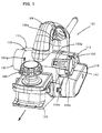
- FIG. 1 is a perspective view showing an entire electric planer according to an embodiment of the invention.
- FIG. 2 is a side view showing the entire electric planer according to the embodiment of the invention.
- FIG. 3 is a sectional perspective view showing a cylindrical chip discharge portion in the state in which a chip discharge unit is not yet mounted.
- FIG. 4 is a sectional perspective view showing the chip discharge unit mounted on the left side of the cylindrical chip discharge portion.
- FIG. 5 is a sectional perspective view showing the chip discharge unit mounted on the right side of the cylindrical chip discharge portion.
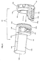
- FIG. 6 is a perspective view of the chip discharge unit.
- FIG. 7 is a sectional view of the chip discharge unit.
- FIG. 8 is a sectional view taken along line A-A in FIG. 7.
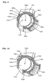
- FIG. 9 is a sectional view showing the cylindrical chip discharge portion with the chip discharge unit mounted thereto and an engagement mechanical part.
- FIG. 10 is a sectional view showing the cylindrical chip discharge portion with the chip discharge unit mounted thereto and an engagement mechanical part, in the disengaged state.
- FIG. 11 is a schematic view showing a modification to the chip discharge mechanism
- Each of the additional features and method steps disclosed above and below may be utilized separately or in conjunction with other features and method steps to provide and manufacture improved electric planers and method for using such electric planers and devices utilized therein. Representative examples of the present invention, which examples utilized many of these additional features and method steps in conjunction, will now be described in detail with reference to the drawings. This detailed description is merely intended to teach a person skilled in the art further details for practicing preferred aspects of the present teachings and is not intended to limit the scope of the invention. Only the claims define the scope of the claimed invention. Therefore, combinations of features and steps disclosed within the following detailed description may not be necessary to practice the invention in the broadest sense, and are instead taught merely to particularly describe some representative examples of the invention, which detailed description will now be given with reference to the accompanying drawings.
- A representative embodiment of the present invention is now described with reference to FIGS. 1 to 10. As shown in FIGS. 1 and 2, an
electric planer 101 includes front andrear bases body 107 as a tool body which is disposed on thebases handle 109 which is connected to the upper surface of thebody 107 and is held by the user. In FIGS. 1 and 2, the direction of travel of theelectric planer 101 during planing operation is shown by an arrow. - The
body 107 includes amotor housing 111, aside housing 113 and acover 115. Themotor housing 111 houses a driving motor 121 (see FIGS. 3 to 5) and a planer blade 127 (see FIG. 2). Theside housing 113 is detachably connected to themotor housing 111 by screws 113a and houses a power transmitting mechanism 117 (see FIGS. 3 to 5) that transmits the rotating output of the drivingmotor 121 to theplaner blade 127. Thecover 115 is removably mounted to theside housing 113 to open and close the side opening of theside housing 113. The drivingmotor 121 and theplaner blade 127 are features that correspond to the "motor" and the "blade", respectively, according to the present invention. - The driving
motor 111 is disposed within themotor housing 111 such that its rotating shaft extends in a horizontal direction that intersects with the direction of travel of theelectric planer 101 during planing operation. Theplaner blade 127, which is not specifically shown, includes a generally cylindrical rotary drum which is supported rotatably on an axis parallel to the rotating shaft of the drivingmotor 121, and a plurality of cutting blades which are mounted on the rotary drum at predetermined intervals in the circumferential direction and extend in the axial direction of the rotary drum. Theplaner blade 127 is disposed in front of the drivingmotor 121, and a lower edge of theplaner blade 127 is exposed below from an opening formed in the bottom of themotor housing 111. As shown in FIGS. 3 to 5, the power transmitting,mechanism 117 includes a driving pulley 117a rotationally driven by the drivingmotor 121, a driven pulley (not shown) that rotates together with theplaner blade 127, and abelt 117b that transmits rotation of the driving pulley 117a to the driven pulley. The drivingmotor 121 is started by depressing a trigger 109a disposed on thehandle 109. Further, agrip 108 is provided on the front upper surface of themotor housing 111. - In order to perform the planing operation by the
planer blade 127, the user holds thehandle 109 and thegrip 108 and depresses the trigger 109a to start the drivingmotor 121. When the drivingmotor 121 is started and theplaner blade 127 is rotationally driven, the user then places thefront bases 103 on the surface of the workpiece and slides it forward along the workpiece. The cutting depth of theplaner blade 127 in the planing operation can be adjusted by adjusting the position of thefront base 103 in the height direction with respect to thebody 107 and thereby changing the amount of protrusion of the lower edge of theplaner blade 127 from the underside of thefront base 103. - A
chip discharging mechanism 131 for discharging chips or shavings generated during operation of planing a workpiece, is explained with reference to FIGS. 3 to 10. Thechip discharging mechanism 131 according to this embodiment includes a cylindricalchip discharge portion 133 having a discharge bore 133a and achip discharge unit 141. The cylindricalchip discharge portion 133 discharges chips to the outside by utilizing motor exhaust air generated when the drivingmotor 121 is driven. The chip discharge unit I41 is removably attached to the cylindricalchip discharge portion 133 and defines the direction of chip discharge. The cylindricalchip discharge portion 133 and thechip discharge unit 141 are features that correspond to the "passage component" and the "discharge direction changing mechanical part", respectively, according to the invention. FIG. 3 shows the cylindricalchip discharge portion 133 in which thechip discharge unit 141 is not yet mounted. FIGS. 4 and 5 show the cylindricalchip discharge portion 133 with thechip discharge unit 141 mounted thereto. FIG. 6 is a perspective view of thechip discharge unit 141. FIGS. 7 and 8 are sectional views of thechip discharge unit 141. FIGS. 9 and 10 are sectional views of thechip discharge unit 141 mounted to the cylindricalchip discharge portion 133. - As shown in FIG. 3, the cylindrical
chip discharge portion 133 is formed in front of the drivingmotor 121 and above theplaner blade 127 within themotor housing 111. The discharge bore 133a of the cylindricalchip discharge portion 133 extends horizontally in the lateral direction that intersects with the direction of travel of theelectric planer 101 during planing operation. The both extending ends of the discharge bore 133a are open. Specifically, the cylindricalchip discharge portion 133 has the discharge bore 133a which are open to the right and the left in the direction of travel of theplaner 101 andform chip outlets outlets recess 133f having a circular arc section and recessed radially outward is formed in the inner wall surface that defines the discharge bore 133a of the cylindricalchip discharge portion 133. Therecess 133f is formed in a predetermined region (overt the range of about 110 to 130° of 360°) in the circumferential direction and has a predetermined length in the extending direction of the discharge bore 133a. The cylindricalchip discharge portion 133 further has anexhaust air inlet 133d for introducing exhaust air used for cooling the drivingmotor 121 into therecess 133f of the discharge bore 133a, and achip inlet 133e for introducing chips generated by planing operation of theplaner blade 127 into the discharge bore 133a. Theexhaust air inlet 133d is a feature that corresponds to the "motor exhaust air inlet" according to this invention. Theexhaust air inlet 133d is formed generally in the middle of therecess 133f in the longitudinal direction (extending direction) and open in the radial direction. - As shown in FIG. 3, a cooling
fan 123 is provided on therotating shaft 121a of the drivingmotor 121 and rotates together with therotating shaft 121a. The coolingfan 123 is disposed within amotor receiving part 111a formed in themotor housing 111 together with the drivingmotor 121. Anexhaust port 111b of air used for cooling the drivingmotor 121 is formed in the front of the motor receiving part Further, an exhaustair guide channel 135 is formed between themotor receiving part 111a and the cylindricalchip discharge portion 133 and guides exhaust air (cooling air) from theexhaust port 111b to theexhaust air inlet 133d. Therefore, when the drivingmotor 121 is driven and thus causes the coolingfan 123 to rotate, outside air is taken as cooling air by a suction force of the coolingfan 123 into themotor receiving part 111 a through an inlet (not shown) which is formed in one axial end of themotor receiving part 111a. The cooling air flows toward the coolingfan 123 within themotor receiving part 111a and thereby cools the drivingmotor 121. As shown in FIGS. 4 and 5 by arrows, the cooling air used for cooling the drivingmotor 121 is discharged from theexhaust port 111b of themotor receiving part 111 a to the exhaustair guide channel 135 and then led into therecess 133f through theexhaust air inlet 133d. - FIGS. 6 to 10 show the
chip discharge unit 141. Thechip discharge unit 141 includes a first mechanical part or a dischargedirection determining member 143 that determines the direction of discharge of chips by selectively closing either theright outlet 133b or theleft outlet 133c of the cylindricalchip discharge portion 133, and a second mechanical part or aremovable cover member 145 that can be removably mounted to the cylindricalchip discharge portion 133. The dischargedirection determining member 143 and theremovable cover member 145 are made of synthetic resin and formed separately from each other. - The chip discharge
direction determining member 143 includes aclosure 143a that closes theoutlet 133b or theoutlet 133c and anair deflector 143b that changes the direction of flow of exhaust air. Theclosure 143a and theair deflector 143b are features that correspond to the "closing member" and the "deflector", respectively, according to the present invention. Theclosure 143a has a generally drum-like shape having a circular external shape and is fitted into either theright outlet 133b or theleft outlet 133c of the cylindricalchip discharge portion 133 and thereby selectively closes theoutlet closure 143a is shown fitted in theleft outlet 133c, and in FIG. 5, theclosure 143a is shown fitted in theright outlet 133b. Theair deflector 143b is integrally formed with theclosure 143a and inserted into the discharge bore 133a together with theclosure 143a when theclosure 143a is fitted into either theright outlet 133b or theleft outlet 133c. - The
air deflector 143b is a plate-like member having a generally circular arc section and extends horizontally from the inner side ofthe end surface of theclosure 143a in the axial direction (the extending direction of the discharge bore 133a). Further, acommunication hole 143c is formed in the proximal end of theair deflector 143b (at the connection between theair deflector 143b and theclosure 143a) and provides communication between the outside and the inside of theair deflector 143b. When theair deflector 143b is inserted into the discharge bore 133a of the cylindricalchip discharge portion 133, theair deflector 143b is placed such that the peripheral edge of theair deflector 143b engages the inner peripheral edge of therecess 133f on the open side. As a result, the internal space of the cylindricalchip discharge portion 133 is partitioned into an upstream region 146a having a generally circular arc section and mainly formed by therecess 133f and adownstream region 146b having a generally circular section and mainly formed by the discharge bore 133a, in isolation from each other (see FIG. 9). The upstream region 146a and thedownstream region 146b are features that correspond to the "first passage" and the "second passage", respectively, according to the present invention. Further, the upstream region 146a and thedownstream region 146b are features that correspond to the "discharge passage" according to the present invention. - The
air deflector 143b partitions the internal space of the cylindricalchip discharge portion 133 into the upstream region 146a and thedownstream region 146b. In the upstream region 146a, exhaust air which has entered therecess 133f through theexhaust air inlet 133d is led toward thecommunication hole 143c (theclosure 143a). In thedownstream region 146b, exhaust air which has entered the exhaust bore 133a through thecommunication hole 143c is turned around in the vicinity of theclosure 143a and led to theopen outlet air deflector 143b is bent radially outward and forms abent portion 143d. Thebent portion 143d is held in contact with the wall surface of the recess I33f. Exhaust air which has entered the upstream region 146a through theexhaust air inlet 133d is led into thedownstream region 146b through thecommunication hole 143c while being prevented from escaping into thedownstream region 146b in the middle of the flow. Further, theair deflector 143b disposed in therecess 133f is configured such that its radially inner wall surface is generally flush with the bore wall surface defining thedownstream region 146b. Thus, chips can be smoothly discharged outside without being caught in thedownstream region 146b. - As shown in FIGS. 6 to 8, the chip discharge
direction determining member 143 and theremovable cover member 145 are placed side by side in the direction of insertion. In order to assemble the dischargedirection determining member 143 and theremovable cover member 145 together, theclosure 143a has acylindrical portion 143e having a diameter smaller than the outside diameter of theclosure 143a, and tworesin springs 143f opposed to each other in the circumferential direction. Thecylindrical portion 143e extends axially from the outside end surface of theclosure 143a (on the side opposite from theair deflector 143b). Anengagement portion 145a of theremovable cover member 145 is fitted onto thecylindrical portion 143e. The tworesin springs 143f extend radially from theclosure 143a within the circular surface region of theclosure 143a. The resin springs 143f serve to define the circumferential position of theremovable cover member 145 with respect to the dischargedirection determining member 143 when theengagement portion 145a of theremovable cover member 145 is fitted onto thecylindrical portion 143e. - The
removable cover member 145 has a stepped cap-like form having thecylindrical engagement portion 145a and acylindrical grip portion 145b which has a larger diameter than theengagement portion 145a and can be held by the user's fingers. As described above, theremovable cover member 145 can be assembled to theclosure 143a of the dischargedirection determining member 143 by fitting theengagement portion 145a onto thecylindrical portion 143e. A plurality ofclaws 145c are formed in the inner wall surface of theengagement portion 145a of theremovable cover member 145 and arranged at appropriate intervals in the circumferential direction. When theengagement portion 145a is fitted onto thecylindrical portion 143e, theclaws 145c engage aring groove 143g formed in the outer circumferential surface of thecylindrical portion 143e. Thus, theremovable cover member 145 is prevented from becoming detached and is allowed in this state to move in the circumferential direction with respect to thecylindrical portion 143e. - Further, a protruding
piece 145d is formed on the inner side of the end surface of thegrip portion 145b of theremovable cover member 145 and extends horizontally toward theclosure 143a. When theengagement portion 145a of theremovable cover member 145 is fitted onto thecylindrical portion 143e, the protrudingpiece 145d is inserted between the opposed resin springs 143f of theclosure 143a and elastically retained by the resin springs 143f (see FIG. 8). As a result, theremovable cover member 145 and the dischargedirection determining member 143 are retained in a predetermined position in the circumferential direction with respect to each other, or in an initial position. When the user holds the grip145b of theremovable cover member 145 and applies an external force to (turns) thegrip portion 145b in the circumferential direction, one of the resin springs 143f is pushed by the protrudingpiece 145d and thus elastically deforms. As a result, theremovable cover member 145 is allowed to move in the circumferential direction with respect to the dischargedirection determining member 143. Specifically, in thechip discharge unit 141, theremovable cover member 145 and the dischargedirection determining member 143 are assembled together such that they are allowed to move a predetermined distance in the circumferential direction with respect to each other, while being integrated in the axial direction (see FIGS. 7 and 8). - As described above, the
chip discharge unit 141 having theremovable cover member 145 and the dischargedirection determining member 143 assembled and integrated together, is inserted into the discharge bore 133a ofthe cylindricalchip discharge portion 133 from the right orleft chip outlet chip discharge unit 141 is removably attached to the cylindricalchip discharge portion 133. Theremovable cover member 145 has aclip 145e that serves to removably lock thechip discharge unit 141 inserted into the discharge bore 133a in that inserted position. Theclip 145e extends in the direction of insertion from a predetermined position on the outer periphery of thegrip portion 145b and has a predetermined length in the axial direction. Further, a generallyrectangular engagement hole 145f is formed in the extending end portion of thegrip portion 145b. As shown in FIGS. 4 and 5, when thechip discharge unit 141 is inserted into the discharge bore 133a of the cylindricalchip discharge portion 133, theengagement hole 145f selectively removably engages either aright projection 133g or aleft projection 133g formed on the outer surface of the cylindricalchip discharge portion 133. Thus, thechip discharge unit 141 is removably locked to the cylindrical chip discharge portion 133 (see FIG. 1). Theclip 145e and theprojections 133g are features that correspond to the "engagement mechanical part", and theclip 145e to the "engagement piece" and theprojections 133g to the "engagement portion", according to this invention. - When the
chip discharge unit 141 is inserted into the discharge bore 133a of the cylindricalchip discharge portion 133, the extending end of theclip 145e contacts theprojection 133g and then climbs over theprojection 133g while elastically deforming, so that theengagement hole 145f engages theprojection 133g. In this engaged state, the wall of theengagement hole 145f and theprojection 133g are locked to each other in a direction opposite to the direction of insertion of thechip discharge unit 141. Thus, thechip discharge unit 141 is retained in the removal prevented state with respect to the discharge bore 133a. The extending end of theclip 145e has a taperedsurface 145g, so that the engagement of theengagement hole 145f of theclip 145e with theprojection 133g can be smoothly performed (see FIGS. 6 and 7). - The engagement between the
clip 145e and theprojection 133g is released by turning theremovable cover member 145 of thechip discharge unit 141 in one circumferential direction. Specifically, as shown in FIGS. 9 and 10, each of the right and left projections 113g formed on the outer surface of the cylindricalchip discharge portion 133 has aninclined surface 133h on the front in the circumferential direction. Therefore, in order to release the engagement between theclip 145e and theprojection 133g, when thechip discharge unit 141 is placed, for example, in theleft outlet 133c, theremovable cover member 145 is turned clockwise (in the direction shown by the arrow in FIG. 10). Then, the wall oftheengagement hole 145f climbs over theprojection 133g while being guided by theinclined surface 133h, so that the engagement between theclip 145e and theprojection 133g is released. This state is shown in FIG. 10. When thechip discharge unit 141 is in theright outlet 133b, theremovable cover member 145 is turned counterclockwise with respect to the direction of insertion. - When the
removable cover member 145 is turned, the dischargedirection determining member 143 is held in engagement with therecess 133f of the cylindricalchip discharge portion 133 and thus prevented from moving (rotating) in the circumferential direction. Therefore, theremovable cover member 145 is turned with respect to the dischargedirection determining member 143 while elastically deforming one of the resin springs 143f via the protrudingpiece 145d. Then, when the engagement between theclip 145e and theprojection 133g is released, theremovable cover member 145 is pulled toward the user. Thus, thechip discharge unit 141 can be removed from the cylindricalchip discharge portion 133. - In the
electric planer 101 having the above-descn'bed construction, in order to discharge chips generated during planing operation, for example, to the right side, as shown in FIG. 4, thechip discharge unit 141 is inserted into the discharge bore 133a from theleft outlet 133c of the cylindrical-chip discharge portion 133. In this state, when the drivingmotor 121 is driven and theplaner blade 127 is rotated, exhaust air generated by rotation of the coolingfan 123 and used for cooling the drivingmotor 121 is led from theexhaust port 111b to theexhaust air inlet 133d via the exhaustair guide channel 135. Then, as shown by arrows in FIG. 4, the exhaust air led into theexhaust air inlet 133d generally linearly flows through the upstream region 146a toward theclosure 143a, and then enters thedownstream region 146b through thecommunication hole 143c. The exhaust air led into thedownstream region 146b is turned around and flows toward the rightopen outlet 133b. - Chips generated during planing operation of the
planer blade 127 are led upward (as shown by the dotted line in FIG. 2) together with the air flow generated by rotation of the planer blade. Then, the chips flow into thedownstream region 146b of the exhaust bore 133a through thechip inlet 133e and are discharged to the outside to the right side through the right outlet I33b by the exhaust air flowing through thedownstream region 146b toward theright outlet 133b. - In order to change the direction of chip discharge from right to left, the
chip discharge unit 141 is removed from the cylindricalchip discharge portion 133. Specifically, as described above, thegrip portion 145b of theremovable cover member 145 is held by the user's fingers and turned such that theclip 145e is disengaged from theprojection 133g of the cylindricalchip discharge portion 133, as shown in FIG. 10. Thereafter, in the disengaged state, theremovable cover member 145 is pulled toward the user. At this time, theremovable cover member 145 is turned with respect to the dischargedirection determining member 143 while elastically deforming one of the resin springs 143f via the protrudingpiece 145d. Therefore, when the dischargedirection determining member 143 is removed from therecess 133f, or when the force of turning theremovable cover member 145 is released in the process of such removal, theremovable cover member 145 and the dischargedirection determining member 143 return to the initial position in which they are placed before the turning operation, by the restoring force of theresin spring 143f. - Then, the
air deflector 143b of thechip discharge unit 141 removed from theleft outlet 133c of the cylindricalchip discharge portion 133 is positioned with respect to therecess 133f such that theair deflector 143b can be fitted into therecess 133f. In this state, theair deflector 143b is inserted into the discharge bore 133a from theright outlet 133b. By this insertion, the outer circumferential surface of theclosure 143a and the outer circumferential surface of theengagement portion 145a oftheremovable cover member 145 are fitted to theoutlet 133b. At the same time, theengagement hole 145f of theclip 145e engages theprojection 133g of the cylindricalchip discharge portion 133. Thus, thechip discharge unit 141 is fixed to the cylindricalchip discharge portion 133 in the removal prevented state (see FIG. 5). Therefore, at this time, chips generated during planing operation can be discharged to the outside from theleft outlet 133c of the discharge bore 133a by the flow of exhaust air which is shown by the arrows in FIG. 5. - According to this embodiment, the direction of chip discharge can be changed by selectively inserting the
chip discharge unit 141 into the discharge bore 133a from the right orleft outlet chip discharge portion 133. - Particularly in this embodiment, the
air deflector 143 partitions the internal space of the cylindricalchip discharge portion 133 into the upstream region 146a and thedownstream region 146b in isolation from each other. Theair deflector 143 guides the exhaust air which has entered the upstream region 146a through theexhaust air inlet 133d, toward theoutlet closure 143a. Thereafter, theair deflector 143 changes the direction of flow of the exhaust air in the vicinity of theclosure 143a and leads the exhaust air to theopen outlet chip discharge portion 133, the internal space of the cylindricalchip discharge portion 133 can be utilized as a chip discharge passage and the distance of the flow of exhaust air through the discharge passage can be increased. As a result, driving noises of the drivingmotor 121 and theplaner blade 127 can be efficiently prevented from leaking out through the discharge bore 133a, so that noise reduction can be effectively achieved. - Further, according to this embodiment, when the
chip discharge unit 141 is inserted into the discharge bore 133a of the cylindricalchip discharge portion 133, theclip 145e formed on thegrip portion 145b of theremovable cover member 145 elastically engages the projection 113g formed on the outer surface ofthe cylindricalchip discharge portion 133. Thus, thechip discharge unit 141 is mounted to the cylindricalchip discharge portion 133 in the removal prevented state. Therefore, thechip discharge unit 141 can be mounted by a simple operation of insertion into the discharge bore 133a of the cylindricalchip discharge portion 133. - The engagement of the
clip 145e with theprojection 133g can be released by turning thechip discharge unit 141 in the direction of insertion. Specifically, thechip discharge unit 141 cannot be removed unless turned in the direction of insertion such that theclip 145e is disengaged from theprojection 133g. Thus, in this construction, the direction of removal of thechip discharge unit 141 is different from the direction of its mounting, so that the mounted state of thechip discharge unit 141 can be more securely maintained in an improved manner. - Further, according to this embodiment, when the
air deflector 143b of thechip discharge unit 141 is engaged with therecess 133f, the radially inner wall surface of theair deflector 143b is flush with the inner wall surface of the discharge bore 133a. Specifically, the radially inner wall surface of theair deflector 143b is smoothly contiguous to the inner wall surface of the discharge bore 133a. Therefore, chips are not easily caught between the radially inner wall surface of theair deflector 143b and the inner wall surface of the discharge bore 133a. Thus, chips can be more effectively and more efficiently discharged. - Further, in this embodiment, the
chip discharge unit 141 is comprised of theremovable cover member 145 and the dischargedirection determining member 143. The protrudingpiece 145d of theremovable cover member 145 is placed between the opposed resin springs 143f of the dischargedirection determining member 143. With this arrangement, theremovable cover member 145 and the dischargedirection determining member 143 can be retained in position in the circumferential direction while being allowed to move with respect to each other in the circumferential direction around the axis extending in the direction of insertion. Thus, the direction of removal of thechip discharge unit 141 can be made different from the direction of its mounting. Further, the radially inner wall surface of theair deflector 143b can be made flush with the inner wall surface of the discharge bore 133a. - Further, in this embodiment, the
recess 133f is formed in the inner wall surface of the discharge bore 133a and theair deflector 143b is disposed within therecess 133f, so that the internal space of the cylindricalchip discharge portion 133 is partitioned into the upstream region 146a and thedownstream region 146b. However, the construction of partitioning the space into the upstream region 146a and thedownstream region 146b is not limited to this. For example, as schematically shown in FIG. 11, theair deflector 143b formed by a plate-like member having a generally U-shaped section may be disposed within the discharge bore 133a such that the space within the discharge bore 133a is partitioned into the upstream region 146a and thedownstream region 146b. In this case, theair deflector 143b is allowed to move (rotate) in the circumferential direction around the axis extending in the direction of insertion. Therefore, theremovable cover member 145 and the dischargedirection determining member 143 forming thechip discharge unit 141 can be formed into one piece.
It is explicitly stated that all features disclosed in the description and/or the claims are intended to be disclosed separately and independently from each other for the purpose of original disclosure as well as for the purpose of restricting the claimed invention independent of the compositions of the features in the embodiments and/or the claims. It is explicitly stated that all value ranges or indications of groups of entities disclose every possible intermediate value or intermediate entity for the purpose of original disclosure as well as for the purpose of restricting the claimed invention, in particular as limits of value ranges. -
- 101 electric planer
- 103 front base
- 105 rear base
- 107 body
- 108 grip
- 109 handle
- 109a trigger
- 111 motor housing
- 111a motor receiving part
- 111b exhaust port
- 113 side housing
- 113a screw
- 115 cover
- 115a screw
- 117 power transmitting mechanism
- 117a driving pulley
- 117b belt
- 121 driving motor
- 121 a rotating shaft
- 123 cooling fan
- 127 planer blade
- 131 chip discharging mechanism
- 133 cylindrical chip discharge portion
- 133a discharge bore
- 133b outlet (opening)
- 133c outlet (opening)
- 133d exhaust air inlet (motor exhaust air inlet)
- 133e chip inlet
- 133f recess
- 133g projection (engagement mechanical part, engagement portion)
- 133h inclined surface
- 135 exhaust air guide channel
- 141 chip discharge unit (discharge direction changing mechanical part)
- 143 discharge direction determining member
- 143a closure (closing member)
- 143b air deflector (deflector)
- 143c communication hole
- 143d bent portion
- 143e cylindrical portion
- 143f resin spring
- 143g ring groove
- 145 removable cover member
- 145a engagement portion
- 145b grip portion
- 145c claw
- 145d protruding piece
- 145e clip (engagement mechanical part, engagement piece)
- 145f engagement hole
- 145g tapered surface
- 146a upstream region (first passage, discharge passage)
- 146b downstream region (second passage, discharge passage)
Claims (6)
- An electric planer comprising:a motor,a planer blade that is rotationally driven by the motor and planes a workpiece anda chip discharging mechanism that discharges chips by using motor exhaust air generated when the motor is driven,wherein the chip discharging mechanism includes a discharge passage that extends in a direction that intersects with the planing direction of the planer blade, openings formed in the both ends of the discharge passage in the extending direction, and a motor exhaust air inlet formed in an intermediate region of the discharge passage in the extending direction, wherein:the chip discharging mechanism further includes a discharge direction changing mechanical part that is separately formed and removably mounted selectively to either one of the openings to thereby determine the discharge direction in which the motor exhaust air is discharged to the outside through the discharge passage,characterized in that the discharge direction changing mechanical part includes a closing member that closes the opening on which the closing member is mounted, and a deflector that changes the direction of flow of the motor exhaust air, and
the deflector extends in the extending direction of the discharge passage and guides the motor exhaust air led into the discharge passage through the motor exhaust air inlet, toward the closing member and then changes the direction of flow of the motor exhaust air in the vicinity of the closing member and leads the motor exhaust air to the other opening which is not closed by the closing member. - The electric planer as defined in claim 1, wherein the deflector partitions the discharge passage into a first passage and a second passage in isolation from each other, wherein the first passage guides the motor exhaust air from the motor exhaust air inlet to the closing member and the second passage guides the motor exhaust air which has been turned around in the vicinity of the closing member, to the other opening.
- The electric planer as defined in claim 1 or 2, wherein:the discharge direction changing mechanical part is inserted into the discharge passage selectively from the one or the other of the openings and removably mounted in the inserted position by an engagement mechanical part,the engagement mechanical part includes an engagement portion and an elastically deformable engagement piece that elastically engages the engagement portion in a direction opposite to the direction of insertion of the discharge direction changing mechanical part, the engagement portion being disposed in one of a passage component forming the discharge passage and the discharge direction changing mechanical part and extending in a direction that intersects with the direction of insertion of the discharge direction changing mechanical part, and the engagement piece being disposed in the other of the passage component and the discharge direction changing mechanical part, andthe engagement piece is disengaged from the engagement portion when rotated in the circumferential direction on the axis extending in the direction of insertion, so that the discharge direction changing mechanical part is allowed to be removed from the discharge passage.
- The electric planer as defined in claim 2, wherein:the discharge passage includes a bore having both ends open in the extending direction, and a recess formed in the inner wall surface of the bore, recessed radially outward and having a predetermined length extending in the extending direction of the bore,the deflector comprises a plate-like member having a circular arc section and having a predetermined length extending in the extending direction of the discharge passage, and the deflector is disposed within the recess and thereby partitions the internal space of the bore into a first passage on the side of the recess and a second passage on the side of the bore, andthe radially inner wall surface of the deflector is smoothly contiguous to the inner wall surface of the bore which defines the second passage.
- The electric planer as defined in claim 3, wherein:the discharge direction changing mechanical part includes a first mechanical part having the closure and the deflector, and a second mechanical part having the engagement mechanical part,the first and second mechanical parts are placed side by side in the direction of insertion of the discharge direction changing mechanical part and are rotatably connected to each other under application of a biasing force of the spring member in the both directions around the direction of insertion of the discharge direction changing mechanical part.
- The electric planer as defined in any one of claims 2 to 5, wherein chips generated during planing the workpiece are led into the second passage of the discharge passage.
Applications Claiming Priority (1)
| Application Number | Priority Date | Filing Date | Title |
|---|---|---|---|
| JP2006233918A JP4805066B2 (en) | 2006-08-30 | 2006-08-30 | Electric fence |
Publications (2)
| Publication Number | Publication Date |
|---|---|
| EP1894688A1 true EP1894688A1 (en) | 2008-03-05 |
| EP1894688B1 EP1894688B1 (en) | 2009-04-22 |
Family
ID=38740196
Family Applications (1)
| Application Number | Title | Priority Date | Filing Date |
|---|---|---|---|
| EP07016862A Not-in-force EP1894688B1 (en) | 2006-08-30 | 2007-08-28 | Electric planer |
Country Status (4)
| Country | Link |
|---|---|
| EP (1) | EP1894688B1 (en) |
| JP (1) | JP4805066B2 (en) |
| DE (1) | DE602007000955D1 (en) |
| RU (1) | RU2435660C2 (en) |
Cited By (5)
| Publication number | Priority date | Publication date | Assignee | Title |
|---|---|---|---|---|
| WO2009060239A3 (en) * | 2007-11-10 | 2009-08-20 | Exakt Prec Tools Ltd | A cap assembly1a combination planer and sander assembly, an a power tool with dust or chip extraction means |
| CN104742197A (en) * | 2013-12-27 | 2015-07-01 | 日立工机株式会社 | Power planer |
| CN118144048A (en) * | 2022-12-06 | 2024-06-07 | 莱克电气绿能科技(苏州)有限公司 | A planing device |
| CN118144049A (en) * | 2022-12-06 | 2024-06-07 | 莱克电气绿能科技(苏州)有限公司 | Electric planer |
| US12589518B2 (en) | 2022-04-25 | 2026-03-31 | Milwaukee Electric Tool Corporation | Hand-held planning tool |
Citations (4)
| Publication number | Priority date | Publication date | Assignee | Title |
|---|---|---|---|---|
| DE4310280A1 (en) | 1993-03-30 | 1994-10-06 | Festo Kg | Mammal power tool for chip removing work |
| JPH07186103A (en) | 1993-12-28 | 1995-07-25 | Hitachi Koki Co Ltd | Electric plane |
| EP1348526A1 (en) | 2002-03-29 | 2003-10-01 | Positec Power Tools (Suzhou) Co. Limited | Planer |
| EP1428620A1 (en) * | 2002-12-09 | 2004-06-16 | Black & Decker Inc. | Planer |
Family Cites Families (8)
| Publication number | Priority date | Publication date | Assignee | Title |
|---|---|---|---|---|
| JPS5329267Y2 (en) * | 1973-09-07 | 1978-07-22 | ||
| JPS6017283Y2 (en) * | 1979-08-18 | 1985-05-28 | 日立工機株式会社 | Cutting mechanism of electric planer |
| SU1014709A1 (en) * | 1981-12-18 | 1983-04-30 | Ленинградский Ордена Трудового Красного Знамени Инженерно-Строительный Институт | Electric planer |
| SU1237429A1 (en) * | 1983-07-06 | 1986-06-15 | Всесоюзный Научно-Исследовательский И Проектно-Конструкторский Институт Механизированного И Ручного Строительно-Монтажного Инструмента,Вибраторов И Строительно-Отделочных Машин | Electrical hard-operated plane |
| DE4117196C2 (en) * | 1991-05-27 | 1998-11-12 | Gerhard Fetzer | Hand plane with frame |
| RU1456U1 (en) * | 1992-07-07 | 1996-01-16 | Владимир Борисович Клейменов | ELECTRIC PLANER |
| RU2047479C1 (en) * | 1993-10-11 | 1995-11-10 | Сергей Ильич Качин | Mechanized plane |
| JP2912168B2 (en) * | 1994-10-18 | 1999-06-28 | リョービ株式会社 | Electric planer with chip discharge mechanism |
-
2006
- 2006-08-30 JP JP2006233918A patent/JP4805066B2/en not_active Expired - Fee Related
-
2007
- 2007-08-28 DE DE602007000955T patent/DE602007000955D1/en active Active
- 2007-08-28 EP EP07016862A patent/EP1894688B1/en not_active Not-in-force
- 2007-08-29 RU RU2007132625/21A patent/RU2435660C2/en not_active IP Right Cessation
Patent Citations (4)
| Publication number | Priority date | Publication date | Assignee | Title |
|---|---|---|---|---|
| DE4310280A1 (en) | 1993-03-30 | 1994-10-06 | Festo Kg | Mammal power tool for chip removing work |
| JPH07186103A (en) | 1993-12-28 | 1995-07-25 | Hitachi Koki Co Ltd | Electric plane |
| EP1348526A1 (en) | 2002-03-29 | 2003-10-01 | Positec Power Tools (Suzhou) Co. Limited | Planer |
| EP1428620A1 (en) * | 2002-12-09 | 2004-06-16 | Black & Decker Inc. | Planer |
Cited By (8)
| Publication number | Priority date | Publication date | Assignee | Title |
|---|---|---|---|---|
| WO2009060239A3 (en) * | 2007-11-10 | 2009-08-20 | Exakt Prec Tools Ltd | A cap assembly1a combination planer and sander assembly, an a power tool with dust or chip extraction means |
| CN104742197A (en) * | 2013-12-27 | 2015-07-01 | 日立工机株式会社 | Power planer |
| US10086529B2 (en) | 2013-12-27 | 2018-10-02 | Hitachi Koki Co., Ltd. | Power planer configured to restrain heat generation of control portion |
| CN104742197B (en) * | 2013-12-27 | 2019-08-09 | 工机控股株式会社 | electric planer |
| US12589518B2 (en) | 2022-04-25 | 2026-03-31 | Milwaukee Electric Tool Corporation | Hand-held planning tool |
| CN118144048A (en) * | 2022-12-06 | 2024-06-07 | 莱克电气绿能科技(苏州)有限公司 | A planing device |
| CN118144049A (en) * | 2022-12-06 | 2024-06-07 | 莱克电气绿能科技(苏州)有限公司 | Electric planer |
| CN118144048B (en) * | 2022-12-06 | 2025-12-30 | 莱克电气绿能科技(苏州)有限公司 | A planing device |
Also Published As
| Publication number | Publication date |
|---|---|
| JP2008055705A (en) | 2008-03-13 |
| JP4805066B2 (en) | 2011-11-02 |
| RU2435660C2 (en) | 2011-12-10 |
| DE602007000955D1 (en) | 2009-06-04 |
| RU2007132625A (en) | 2009-03-10 |
| EP1894688B1 (en) | 2009-04-22 |
Similar Documents
| Publication | Publication Date | Title |
|---|---|---|
| EP1894688B1 (en) | Electric planer | |
| CA2536920C (en) | Accessory attachment for rotary hand tools | |
| US8834641B2 (en) | Method of use for debris removal system for power tool | |
| EP2567779A1 (en) | Power tool dust collecting device and power tool | |
| CN217666841U (en) | Cutting saw | |
| US20220297209A1 (en) | Cutting tool | |
| TWM575366U (en) | Power tool and cut-off saw | |
| US10086529B2 (en) | Power planer configured to restrain heat generation of control portion | |
| EP2813310B1 (en) | Saw with blower housing | |
| EP2535133B1 (en) | Engine-driven cutter | |
| WO2013070937A2 (en) | Power tool having interchangeable tool heads with an independent accessory switch | |
| CN101542101B (en) | Arrangement related to a motor-driven tool | |
| WO2012090480A2 (en) | Engine-operated machine | |
| US20070022605A1 (en) | Nose hair cutter | |
| EP2363231B1 (en) | Engine-driven cutter | |
| US20110214657A1 (en) | Engine-driven cutter | |
| EP4506126A1 (en) | A router and chip collector accessory therefor | |
| US20160265491A1 (en) | Power working machine | |
| US8739418B2 (en) | Engine-driven cutter | |
| BRPI1101408A2 (en) | motor driven cutter | |
| CN218740604U (en) | Filter and chain saw | |
| US6786192B2 (en) | Portable, manually guided implement | |
| JP2010000630A (en) | Cutter | |
| JP5788746B2 (en) | Dust collector for power tool and power tool | |
| US12589518B2 (en) | Hand-held planning tool |
Legal Events
| Date | Code | Title | Description |
|---|---|---|---|
| PUAI | Public reference made under article 153(3) epc to a published international application that has entered the european phase |
Free format text: ORIGINAL CODE: 0009012 |
|
| AK | Designated contracting states |
Kind code of ref document: A1 Designated state(s): AT BE BG CH CY CZ DE DK EE ES FI FR GB GR HU IE IS IT LI LT LU LV MC MT NL PL PT RO SE SI SK TR |
|
| AX | Request for extension of the european patent |
Extension state: AL BA HR MK YU |
|
| 17P | Request for examination filed |
Effective date: 20080829 |
|
| AKX | Designation fees paid |
Designated state(s): DE FR GB |
|
| GRAP | Despatch of communication of intention to grant a patent |
Free format text: ORIGINAL CODE: EPIDOSNIGR1 |
|
| GRAS | Grant fee paid |
Free format text: ORIGINAL CODE: EPIDOSNIGR3 |
|
| GRAA | (expected) grant |
Free format text: ORIGINAL CODE: 0009210 |
|
| AK | Designated contracting states |
Kind code of ref document: B1 Designated state(s): DE FR GB |
|
| REG | Reference to a national code |
Ref country code: GB Ref legal event code: FG4D |
|
| REF | Corresponds to: |
Ref document number: 602007000955 Country of ref document: DE Date of ref document: 20090604 Kind code of ref document: P |
|
| PLBE | No opposition filed within time limit |
Free format text: ORIGINAL CODE: 0009261 |
|
| STAA | Information on the status of an ep patent application or granted ep patent |
Free format text: STATUS: NO OPPOSITION FILED WITHIN TIME LIMIT |
|
| 26N | No opposition filed |
Effective date: 20100125 |
|
| PGFP | Annual fee paid to national office [announced via postgrant information from national office to epo] |
Ref country code: DE Payment date: 20130821 Year of fee payment: 7 |
|
| PGFP | Annual fee paid to national office [announced via postgrant information from national office to epo] |
Ref country code: GB Payment date: 20130828 Year of fee payment: 7 Ref country code: FR Payment date: 20130808 Year of fee payment: 7 |
|
| REG | Reference to a national code |
Ref country code: DE Ref legal event code: R119 Ref document number: 602007000955 Country of ref document: DE |
|
| GBPC | Gb: european patent ceased through non-payment of renewal fee |
Effective date: 20140828 |
|
| REG | Reference to a national code |
Ref country code: FR Ref legal event code: ST Effective date: 20150430 |
|
| REG | Reference to a national code |
Ref country code: DE Ref legal event code: R119 Ref document number: 602007000955 Country of ref document: DE Effective date: 20150303 |
|
| PG25 | Lapsed in a contracting state [announced via postgrant information from national office to epo] |
Ref country code: DE Free format text: LAPSE BECAUSE OF NON-PAYMENT OF DUE FEES Effective date: 20150303 Ref country code: GB Free format text: LAPSE BECAUSE OF NON-PAYMENT OF DUE FEES Effective date: 20140828 |
|
| PG25 | Lapsed in a contracting state [announced via postgrant information from national office to epo] |
Ref country code: FR Free format text: LAPSE BECAUSE OF NON-PAYMENT OF DUE FEES Effective date: 20140901 |