EP1892850A2 - Wireless communication apparatus and wireless communication method - Google Patents
Wireless communication apparatus and wireless communication method Download PDFInfo
- Publication number
- EP1892850A2 EP1892850A2 EP07114676A EP07114676A EP1892850A2 EP 1892850 A2 EP1892850 A2 EP 1892850A2 EP 07114676 A EP07114676 A EP 07114676A EP 07114676 A EP07114676 A EP 07114676A EP 1892850 A2 EP1892850 A2 EP 1892850A2
- Authority
- EP
- European Patent Office
- Prior art keywords
- wireless communication
- code book
- data
- communication apparatus
- base station
- Prior art date
- Legal status (The legal status is an assumption and is not a legal conclusion. Google has not performed a legal analysis and makes no representation as to the accuracy of the status listed.)
- Granted
Links
Images




Classifications
-
- H—ELECTRICITY
- H04—ELECTRIC COMMUNICATION TECHNIQUE
- H04B—TRANSMISSION
- H04B7/00—Radio transmission systems, i.e. using radiation field
- H04B7/02—Diversity systems; Multi-antenna system, i.e. transmission or reception using multiple antennas
- H04B7/04—Diversity systems; Multi-antenna system, i.e. transmission or reception using multiple antennas using two or more spaced independent antennas
- H04B7/06—Diversity systems; Multi-antenna system, i.e. transmission or reception using multiple antennas using two or more spaced independent antennas at the transmitting station
- H04B7/0613—Diversity systems; Multi-antenna system, i.e. transmission or reception using multiple antennas using two or more spaced independent antennas at the transmitting station using simultaneous transmission
- H04B7/0615—Diversity systems; Multi-antenna system, i.e. transmission or reception using multiple antennas using two or more spaced independent antennas at the transmitting station using simultaneous transmission of weighted versions of same signal
- H04B7/0617—Diversity systems; Multi-antenna system, i.e. transmission or reception using multiple antennas using two or more spaced independent antennas at the transmitting station using simultaneous transmission of weighted versions of same signal for beam forming
-
- H—ELECTRICITY
- H04—ELECTRIC COMMUNICATION TECHNIQUE
- H04B—TRANSMISSION
- H04B7/00—Radio transmission systems, i.e. using radiation field
- H04B7/02—Diversity systems; Multi-antenna system, i.e. transmission or reception using multiple antennas
- H04B7/04—Diversity systems; Multi-antenna system, i.e. transmission or reception using multiple antennas using two or more spaced independent antennas
- H04B7/06—Diversity systems; Multi-antenna system, i.e. transmission or reception using multiple antennas using two or more spaced independent antennas at the transmitting station
- H04B7/0613—Diversity systems; Multi-antenna system, i.e. transmission or reception using multiple antennas using two or more spaced independent antennas at the transmitting station using simultaneous transmission
- H04B7/0615—Diversity systems; Multi-antenna system, i.e. transmission or reception using multiple antennas using two or more spaced independent antennas at the transmitting station using simultaneous transmission of weighted versions of same signal
- H04B7/0619—Diversity systems; Multi-antenna system, i.e. transmission or reception using multiple antennas using two or more spaced independent antennas at the transmitting station using simultaneous transmission of weighted versions of same signal using feedback from receiving side
- H04B7/0636—Feedback format
- H04B7/0639—Using selective indices, e.g. of a codebook, e.g. pre-distortion matrix index [PMI] or for beam selection
-
- H—ELECTRICITY
- H04—ELECTRIC COMMUNICATION TECHNIQUE
- H04B—TRANSMISSION
- H04B17/00—Monitoring; Testing
- H04B17/20—Monitoring; Testing of receivers
- H04B17/24—Monitoring; Testing of receivers with feedback of measurements to the transmitter
-
- H—ELECTRICITY
- H04—ELECTRIC COMMUNICATION TECHNIQUE
- H04B—TRANSMISSION
- H04B7/00—Radio transmission systems, i.e. using radiation field
- H04B7/02—Diversity systems; Multi-antenna system, i.e. transmission or reception using multiple antennas
- H04B7/04—Diversity systems; Multi-antenna system, i.e. transmission or reception using multiple antennas using two or more spaced independent antennas
- H04B7/06—Diversity systems; Multi-antenna system, i.e. transmission or reception using multiple antennas using two or more spaced independent antennas at the transmitting station
- H04B7/0613—Diversity systems; Multi-antenna system, i.e. transmission or reception using multiple antennas using two or more spaced independent antennas at the transmitting station using simultaneous transmission
- H04B7/0615—Diversity systems; Multi-antenna system, i.e. transmission or reception using multiple antennas using two or more spaced independent antennas at the transmitting station using simultaneous transmission of weighted versions of same signal
- H04B7/0619—Diversity systems; Multi-antenna system, i.e. transmission or reception using multiple antennas using two or more spaced independent antennas at the transmitting station using simultaneous transmission of weighted versions of same signal using feedback from receiving side
- H04B7/0621—Feedback content
- H04B7/0634—Antenna weights or vector/matrix coefficients
-
- H—ELECTRICITY
- H04—ELECTRIC COMMUNICATION TECHNIQUE
- H04B—TRANSMISSION
- H04B7/00—Radio transmission systems, i.e. using radiation field
- H04B7/02—Diversity systems; Multi-antenna system, i.e. transmission or reception using multiple antennas
- H04B7/04—Diversity systems; Multi-antenna system, i.e. transmission or reception using multiple antennas using two or more spaced independent antennas
- H04B7/06—Diversity systems; Multi-antenna system, i.e. transmission or reception using multiple antennas using two or more spaced independent antennas at the transmitting station
- H04B7/0613—Diversity systems; Multi-antenna system, i.e. transmission or reception using multiple antennas using two or more spaced independent antennas at the transmitting station using simultaneous transmission
- H04B7/0667—Diversity systems; Multi-antenna system, i.e. transmission or reception using multiple antennas using two or more spaced independent antennas at the transmitting station using simultaneous transmission of delayed versions of same signal
- H04B7/0673—Diversity systems; Multi-antenna system, i.e. transmission or reception using multiple antennas using two or more spaced independent antennas at the transmitting station using simultaneous transmission of delayed versions of same signal using feedback from receiving side
Definitions
- the present invention relates to wireless communication and transmission directivity.
- Beamforming transmits a single datum via multiple antennas imparting directivity by the multiple antennas by staggering phases on transmission.
- Fig. 9 is a schematic showing a conventional wireless communication apparatus.
- Fig. 9 shows the partial configuration of the wireless communication apparatus on the base station side of a mobile communication system.
- Data from multiple channels (four channels shown in the figure) is input to a precoder 901, and each channel is given a fixed phase difference to form multiple beams.
- a transmitting unit 902 includes transmission circuits 902a to 902d for each channel, and transmits data via an antenna 903.
- Fig. 9 While the configuration shown in Fig. 9 is the configuration of a beamformer that attains a given directivity using the multiple antenna 903, a similar technique that transmits data by imparting phase differences to each channel exists, a multiple input multiple output (MIMO) technique, in which different data is transmitted by each channel (for example, Published Japanese translation of a PCT application No. 2005-522086 ).
- MIMO multiple input multiple output
- phase variation there is phase variation among the transmission circuits 902a to 902d for each channel of the transmitting unit 902.
- the existence of the phase variation causes, at the transmitting unit 902, distortion of the beam formed at the precoder 901, and expected directivity cannot be obtained.
- Fig. 10 illustrates gain reduction of multi-beam transmission.
- expected directivity is obtained and transmission can be done with an improved gain (up to 6 decibels (dB)) by the effect of the multi-beam method.
- directivity becomes inadequate, e.g., broaden, and the gains of each beam is reduced (down to 4 dB).
- phase adjustment has formerly been required so that phase variation does not occur by comparing the outputs of the transmission circuits 902a to 902d of the transmitting unit 902 and a reference signal using an external calibrator.
- a wireless communication apparatus on a base station side, that performs beamforming and transmits data to a mobile station using a plurality of antennas, includes a code book that stores beamforming information; a precoder that reads the code book and performs processing to form a multi-beam pattern for the data; and a control unit that, based on feedback information for a compensation of a phase variation in each transmission circuit of a plurality of transmission circuits that each respectively corresponds to a channel, controls a retrieval of the beamforming information that compensates the phase variation.
- a wireless communication apparatus on a mobile station side, that receives a plurality of beams of data from a base station using a plurality of antennas, includes a code book that stores beamforming information identical to that stored in a code book of the base station; and a control unit that, when notified that a phase variation compensation is required by the base station, searches the beamforming information, based on a signal condition of each of the beams, for the beamforming information that enables optimal beamforming, and transmits the selected beamforming information to the base station as feedback information.
- a wireless communication method on a base station side, of performing beamforming and transmitting data to a mobile station using a plurality of antennas, includes reading beamforming information stored in a code book; forming a multi-beam pattern for the data; and retrieving, based on feedback information for a compensation of ;:3 phase variation in each transmission circuit of a plurality of transmission circuits that each respectively correspond to a channel, the beamforming information to compensate the phase variation.
- a wireless communication method of a wireless communication apparatus on a mobile station side that, using a plurality of antennas, receives a plurality of beams of data from a base station, includes searching, based on a signal condition of each of the beams when notified that a phase variation compensation is required by the base station, a code book for beamforming information that enables optimal beamforming, the code book storing beamforming information identical to that in a code book provided in the base station; and transmitting the beamforming information that enables optimal beamforming to the base station as feedback information.
- Fig. 1 is a schematic showing the configuration of wireless communication apparatuses according to a first embodiment of the present invention.
- Wireless communication apparatuses 10 and 50 of a base station (transmitter) and of a mobile station (receiver), respectively, are shown of mobile communication system.
- Data (data stream) for multiple channels is input to a precoder 11, and given phase differences are assigned to each channel to form multiple beams.
- a code book 21 stores 16-way (equal to the number of combination of indices) compensation values to give weights to the data of each channel according to the multi-beam pattern.
- a transmitting unit 13 includes transmission circuits 13a to 13d for individual channels, and modulates data at the oscillation frequency (RF) of an oscillator 14 (14a to 14d) and outputs the data via multiple antennas 15.
- RF oscillation frequency
- a control unit 22 compensates phase variation based on the data input by the wireless communication apparatus 50 of a mobile station and selects a compensation value from the code book 21 and inputs the value to the precoder 11 to compensate phase variation.
- the wireless communication apparatus 50 on the mobile station side is explained.
- Data received through multiple channels (two channels shown in the figure) via antennas 51 is input to a channel estimation unit 52, and the channel estimation unit 52 estimates the channels using orthogonal pilot components included in the transmitted data, and a demodulator 53 demodulates stream data and outputs demodulated data.
- a demodulator 53 demodulates stream data and outputs demodulated data.
- SIMO single input multiple output
- the wireless communication apparatus 50 on the mobile station side is also equipped with a code book 61 that contains the same contents as that on the base station side.
- a beam measuring unit 62 based on channel values estimated by the channel estimating unit 52 and the contents of the code book 61, alters estimated channel values necessary for the compensation of the variation in the received beams.
- a beam indicating the maximum signal to interference plus noise ratio (SINR) (signal to interference ratio (SIR)) is measured, and the optimal transmission beam and the number cf streams are selected by a selecting unit 63, and the information is fed back to the wireless communication apparatus 10 of the case station.
- Feedback information only includes the transmission beam and the number of streams, and thus can easily be transmitted to the base station side without compressing the band of an upstream transmission path.
- the beam measuring unit 62 and the selecting unit 63 constitute a control unit in the wireless communication apparatus 50 on the mobile station side.
- Fig. 2 is a schematic showing detailed configuration of the beam measuring unit shown in Fig. 1.
- the beam measuring unit includes a channel value estimating unit 62A and an SINR estimating unit 62B.
- the channel value estimating unit 62A computes an estimate channel value HW for each beam based on an estimate channel value H output by the channel estimating unit 52 and a weight W set in the code book 61.
- the SINR estimating unit 62B estimates the level, e.g., SINR, of each beam using the estimate channel value HW of each beam. The estimation can be done not only by SINR but also by signal power.
- the selecting unit 63 compares the level of each beam with a threshold value, and ranks the beams in ascending order of level.
- Transmission beam identifiers (ID's) which are assigned to each high ranking beam, and the determined number of streams are transmitted as feedback information to the wireless communication apparatus 10 on the base station side.
- the code books 21 and 61 include weights to form the beam pattern of multiple beams and to compensate phase variation.
- the weight W for multi-beam generation is expressed by the following equation 1 (j and -j are imaginary numbers).
- the weight W is defined from W(0, 0) to W(3, 3) in the following sixteen ways according to combinations of the index numbers: W(0, 0), W(0, 1), W(0, 2), W(0, 3), W(1, 0), W(1, 1), W(1, 2), W(1, 3), W(2, 0), W(2, 1), W(2, 2), W(2, 3), W(3, O), W(3, 1), W(3, 2), W(3, 3).
- a code book to obtain high gains is prepared by compensating phase variations existing in the channels of the transmission circuits 13a to 13d of the transmitting unit 13.
- the matrix is expressed as equation 2.
- Equation 3 is computed by normalizing the diagonal matrix after discrete Fourier transform (DFT) and Hermitian transposition.
- DFT discrete Fourier transform
- the beam measuring unit 62 of the wireless communication apparatus 50 on the reception side uses the code book 61, computes the following equation 4, where phase terms to compensate phase variation are added to a third and a fourth antenna of the antennas 15 for transmission.
- the beam number wi of the maximum SINR and the phase number thereof (matrix number) m 3 and m 4 are obtained and are transmitted as feedback information to the wireless communication apparatus 10 on the base station side.
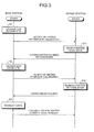
- Fig. 3 is a flowchart showing processes related to phase variation compensation. Processes by wireless communication apparatuses of both a base and a mobile station are shown.
- the base station notifies or informs the mobile station of incomplete calibration if calibration for phase variation compensation is not completed (step S1). Receiving the notification or information, the mobile station searches the entire code book 61 (step S11).
- Fig. 4 is a schematic showing a state of a code book during the search. The entire 16-way code book is searched.
- the mobile station then informs the base station of a matrix number as the result of the search for phase variation compensation and a beam number based on beam measurement by the beam measuring unit 62 as feedback information.
- Fig. 4 shows an example in which matrix number nine and beam number two are reported.
- the base station completes calibration based on the feedback information (step S2). At this time, a matrix number and a beam number indicated by the feedback information are read from the code book 21 and are input to the precoder 11, and thus optimum beamforming can be performed. The base station notifies or informs the mobile station of the completion of calibration.
- Fig. 5 is a schematic showing the state of a code book during a partial search, "partial" meaning searching for a beam number within the matrix number nine that is obtained by the search of an entire code book. Once phase variation is compensated, only the search of an optimum beam number that constantly indicates the maximum SINR is required without searching an entire code book.
- Fig. 5 shows an example in which beam number three (search result) is reported to the base station.
- the base station transmits data (step S3).
- the data transmission is performed using the matrix number and beam number reported by the mobile station and one cycle of the process is thus completed.
- Fig. 6 is a timing chart showing the transition of searching status. After the search of the entire code book 61 (step S11), only partial searching (step S21) needs to be performed at a fixed time intervals. It is not necessary to search the entire code book 61 at every calibration process, and thus time for partial searching can be increased. In this way, the search process of the code book 61 in the wireless communication apparatus 50 on the mobile station side can be simplified, and the processing load involved in the search can be reduced.
- the phase variation of each transmission, circuit 13a to 13d of the transmitting unit 13 in the wireless communication apparatus 10 of the base station is compensated on the base station side using the feedback information that is output by the wireless communication apparatus 50 of the mobile station based on the receiving condition.
- the compensation of phase variation can be performed simply without any specific calibration circuit.
- Fig. 7 is a schematic of a wireless communication apparatus according to a second embodiment of the present invention.
- a single oscillator, an oscillator 14, is connected to the multiple channels of the transmitting unit 13, differentiating the apparatus from that of Fig. 1 according to the first embodiment.
- the oscillator 14 supplies a local signal that is common to each transmission circuit of the transmitting unit 13. Therefore, phase variation among the transmission circuits 13a to 13d is not generated.
- Fig. 8 is a timing chart showing search status transition. According to the second embodiment, the same process as shown in Fig. 3 is also performed by the wireless communication apparatus 50 on the mobile station side. Similarly, a partial search (step S21) is performed after the entire code book 61 is searched (step S11) at the mobile station.
- the oscillator 14 supplies the transmitting unit 13 with a common local signal and thus phase variations among channels are not induced, a single search of the entire code book 61 at a calibration process is sufficient. After a single search of the entire code book 61 is performed, the duration of the partial search can be longer (the relative proportion of the partial search time can be increased) compared to the first embodiment. Search of the entire code book 61 at fixed time intervals (for example, thirty-minute cycles) based on temperature shift, and compensation, also at a fixed time intervals based on temperature shift, of phase variation induced at the transmitting unit 13 may be performed.
- the wireless communication apparatus 50 on the mobile station side recognizes, by information transmitted from the base station side, that the transmitting unit 13 of the wireless communication apparatus 10 on the base station side has a configuration employing a common local signal.
- a single oscillator the oscillator 14 supplies a common local signal to each of the transmission circuits 13a to 13d of the transmitting unit 13 in the wireless communication apparatus 10 of the base station, and phase variation is compensated on the base station side using the feedback information that is output by the wireless communication apparatus 50 of the mobile station based on the receiving condition.
- phase variation can be performed simply without any specific calibration circuit, the search cycle of an entire code book can be increased, and the partial search time can be relatively increased. Furthermore, simplification of the configuration and reduction of the processing load to the mobile station can be realized.
- each embodiment above is explained with the example of an SIMO configuration that receives data input by a single user as a single stream, performs beamforming to transmit the data in multiple beams.
- the embodiments can also be applied to an MIMO configuration that receives multi-stream data input by multiple users, and transmits the data by multiple beams.
- the method related to the wireless communication explained in the present embodiments can be realized by executing a prepared program on a computer, such as a personal computer or work station.
- the program is recorded on computer-readable recording medium such as a hard disk, flexible disk, compact disk read-only memory (CD-ROM), magneto optical disk (MO), or digital versatile disk (DVD), and is read and executed by a computer.
- the program can be a transmittable medium that can be distributed via networks, such as the internet.
- the wireless communication apparatus effects improvement of gain on the mobile station side and expected multi-beam directivity by compensating phase variation with a simple configuration to merely control the reading of optimum code book on the base station side without any specific calibrator.
- the invention also provides a computer program or a computer program product for carrying out any of the methods described herein, and a computer readable medium having stored thereon a program for carrying out any of the methods described herein.
- a computer program embodying the invention may be stored on a computer-readable medium, or it could, for example, be in the form of a signal such as a downloadable data signal provided from an Internet website, or it could be in any other form.
Landscapes
- Engineering & Computer Science (AREA)
- Computer Networks & Wireless Communication (AREA)
- Signal Processing (AREA)
- Physics & Mathematics (AREA)
- Mathematical Physics (AREA)
- Electromagnetism (AREA)
- Radio Transmission System (AREA)
- Mobile Radio Communication Systems (AREA)
Abstract
Description
- The present invention relates to wireless communication and transmission directivity.
- For the transmission and reception of data using multiple antennas, a beamforming technique has been employed. Beamforming transmits a single datum via multiple antennas imparting directivity by the multiple antennas by staggering phases on transmission.
- Fig. 9 is a schematic showing a conventional wireless communication apparatus. Fig. 9 shows the partial configuration of the wireless communication apparatus on the base station side of a mobile communication system. Data from multiple channels (four channels shown in the figure) is input to a
precoder 901, and each channel is given a fixed phase difference to form multiple beams. A transmittingunit 902 includestransmission circuits 902a to 902d for each channel, and transmits data via anantenna 903. - While the configuration shown in Fig. 9 is the configuration of a beamformer that attains a given directivity using the
multiple antenna 903, a similar technique that transmits data by imparting phase differences to each channel exists, a multiple input multiple output (MIMO) technique, in which different data is transmitted by each channel (for example, PublishedJapanese translation of a PCT application No. 2005-522086 - In the configuration shown in Fig. 9, however, there is phase variation among the
transmission circuits 902a to 902d for each channel of the transmittingunit 902. The existence of the phase variation causes, at the transmittingunit 902, distortion of the beam formed at theprecoder 901, and expected directivity cannot be obtained. - Fig. 10 illustrates gain reduction of multi-beam transmission. As shown on the left side of the figure, under a condition in which there is no phase variation, expected directivity is obtained and transmission can be done with an improved gain (up to 6 decibels (dB)) by the effect of the multi-beam method. Inversely, in the case that phase variation exists in the
transmission circuits 902a to 902d of the transmittingunit 902, directivity becomes inadequate, e.g., broaden, and the gains of each beam is reduced (down to 4 dB). - Therefore, in order to eliminate phase variation, phase adjustment has formerly been required so that phase variation does not occur by comparing the outputs of the
transmission circuits 902a to 902d of the transmittingunit 902 and a reference signal using an external calibrator. - It is desirable to at least solve the above problems in the conventional technologies.
- According to an embodiment of one aspect of the present invention includes, a wireless communication apparatus, on a base station side, that performs beamforming and transmits data to a mobile station using a plurality of antennas, includes a code book that stores beamforming information; a precoder that reads the code book and performs processing to form a multi-beam pattern for the data; and a control unit that, based on feedback information for a compensation of a phase variation in each transmission circuit of a plurality of transmission circuits that each respectively corresponds to a channel, controls a retrieval of the beamforming information that compensates the phase variation.
- According to an embodiment of another aspect of the present invention, a wireless communication apparatus, on a mobile station side, that receives a plurality of beams of data from a base station using a plurality of antennas, includes a code book that stores beamforming information identical to that stored in a code book of the base station; and a control unit that, when notified that a phase variation compensation is required by the base station, searches the beamforming information, based on a signal condition of each of the beams, for the beamforming information that enables optimal beamforming, and transmits the selected beamforming information to the base station as feedback information.
- According to an embodiment of still another aspect of the present invention, a wireless communication method, on a base station side, of performing beamforming and transmitting data to a mobile station using a plurality of antennas, includes reading beamforming information stored in a code book; forming a multi-beam pattern for the data; and retrieving, based on feedback information for a compensation of ;:3 phase variation in each transmission circuit of a plurality of transmission circuits that each respectively correspond to a channel, the beamforming information to compensate the phase variation.
- According to an embodiment of yet another aspect of the present invention, a wireless communication method of a wireless communication apparatus on a mobile station side that, using a plurality of antennas, receives a plurality of beams of data from a base station, includes searching, based on a signal condition of each of the beams when notified that a phase variation compensation is required by the base station, a code book for beamforming information that enables optimal beamforming, the code book storing beamforming information identical to that in a code book provided in the base station; and transmitting the beamforming information that enables optimal beamforming to the base station as feedback information.
- The other features, and advantages of the present invention are specifically set forth in or will become apparent from the following detailed description of the invention when read in conjunction with the accompanying drawings.
-
- Fig. 1 is a schematic showing the configuration of wireless communication apparatuses according to a first embodiment of the present invention;
- Fig. 2 is a schematic showing detailed configuration of the beam measuring unit shown in Fig. 1;
- Fig. 3 is a flowchart showing processes related to phase variation compensation;
- Fig. 4 is a schematic showing a state: of a code book during the search;
- Fig. 5 is a schematic showing the state of a cede book during a partial search;
- Fig. 6 is a timing chart showing the transition of searching status;
- Fig. 7 is a schematic of a wireless communication apparatus according to a second embodiment of the present invention;
- Fig. 8 is a timing chart showing search status transition;
- Fig. 9 is a schematic showing a conventional wireless communication apparatus; and
- Fig. 10 illustrates gain reduction of multi-beam transmission.
- Referring to the accompanying drawings, exemplary embodiments according to the present invention are explained in detail below.
- Fig. 1 is a schematic showing the configuration of wireless communication apparatuses according to a first embodiment of the present invention.
Wireless communication apparatuses - The
wireless communication apparatus 10 on the base station side is explained. Data (data stream) for multiple channels (four channels shown in the figure) is input to aprecoder 11, and given phase differences are assigned to each channel to form multiple beams. Acode book 21 stores 16-way (equal to the number of combination of indices) compensation values to give weights to the data of each channel according to the multi-beam pattern. - The pilot signal of an orthogonal component (orthogonal pilot) is individually added to the output data of each channel of the
precoder 11 by an addingunit 12. A transmittingunit 13 includestransmission circuits 13a to 13d for individual channels, and modulates data at the oscillation frequency (RF) of an oscillator 14 (14a to 14d) and outputs the data viamultiple antennas 15. - A
control unit 22 compensates phase variation based on the data input by thewireless communication apparatus 50 of a mobile station and selects a compensation value from thecode book 21 and inputs the value to theprecoder 11 to compensate phase variation. - The
wireless communication apparatus 50 on the mobile station side is explained. Data received through multiple channels (two channels shown in the figure) viaantennas 51 is input to achannel estimation unit 52, and thechannel estimation unit 52 estimates the channels using orthogonal pilot components included in the transmitted data, and ademodulator 53 demodulates stream data and outputs demodulated data. Although the system shown in Fig. 1 is the example of single input multiple output (SIMO) configuration, it can be applied similarly to an MIMO system. - The
wireless communication apparatus 50 on the mobile station side is also equipped with acode book 61 that contains the same contents as that on the base station side. Abeam measuring unit 62, based on channel values estimated by thechannel estimating unit 52 and the contents of thecode book 61, alters estimated channel values necessary for the compensation of the variation in the received beams. At this time, a beam indicating the maximum signal to interference plus noise ratio (SINR) (signal to interference ratio (SIR)) is measured, and the optimal transmission beam and the number cf streams are selected by a selectingunit 63, and the information is fed back to thewireless communication apparatus 10 of the case station. Feedback information only includes the transmission beam and the number of streams, and thus can easily be transmitted to the base station side without compressing the band of an upstream transmission path. Thebeam measuring unit 62 and the selectingunit 63 constitute a control unit in thewireless communication apparatus 50 on the mobile station side. - Fig. 2 is a schematic showing detailed configuration of the beam measuring unit shown in Fig. 1. The beam measuring unit includes a channel
value estimating unit 62A and an SINR estimatingunit 62B. The channelvalue estimating unit 62A computes an estimate channel value HW for each beam based on an estimate channel value H output by thechannel estimating unit 52 and a weight W set in thecode book 61. The SINR estimatingunit 62B estimates the level, e.g., SINR, of each beam using the estimate channel value HW of each beam. The estimation can be done not only by SINR but also by signal power. - The selecting
unit 63 compares the level of each beam with a threshold value, and ranks the beams in ascending order of level. Transmission beam identifiers (ID's), which are assigned to each high ranking beam, and the determined number of streams are transmitted as feedback information to thewireless communication apparatus 10 on the base station side. - The
code books 
- As code book information for precoding, the weight W is defined from W(0, 0) to W(3, 3) in the following sixteen ways according to combinations of the index numbers: W(0, 0), W(0, 1), W(0, 2), W(0, 3), W(1, 0), W(1, 1), W(1, 2), W(1, 3), W(2, 0), W(2, 1), W(2, 2), W(2, 3), W(3, O), W(3, 1), W(3, 2), W(3, 3).
- A code book to obtain high gains is prepared by compensating phase variations existing in the channels of the
transmission circuits 13a to 13d of the transmittingunit 13. In the case of four indices as the above, when a 4x4 diagonal matrix is described as D(m3, m4) and the phase difference is ninety degrees, the matrix is expressed asequation 2. By assigning the two of four matrix arrangements that are diagonally arranged from the upper left to the lower right, as 1 and 1, virtual straight lines positioned at angles differing by 90° are created. Terms for approaching the virtual straight line are φ (m3) and φ (m4).
-
Equation 3 is computed by normalizing the diagonal matrix after discrete Fourier transform (DFT) and Hermitian transposition.
- As a result, a unitary matrix for preceding is obtained and is stored in the
code books - Consequently, the
beam measuring unit 62 of thewireless communication apparatus 50 on the reception side, using thecode book 61, computes thefollowing equation 4, where phase terms to compensate phase variation are added to a third and a fourth antenna of theantennas 15 for transmission.
- The beam number wi of the maximum SINR and the phase number thereof (matrix number) m3 and m4 are obtained and are transmitted as feedback information to the
wireless communication apparatus 10 on the base station side. - Fig. 3 is a flowchart showing processes related to phase variation compensation. Processes by wireless communication apparatuses of both a base and a mobile station are shown.
- The base station notifies or informs the mobile station of incomplete calibration if calibration for phase variation compensation is not completed (step S1). Receiving the notification or information, the mobile station searches the entire code book 61 (step S11). Fig. 4 is a schematic showing a state of a code book during the search. The entire 16-way code book is searched.
- The mobile station then informs the base station of a matrix number as the result of the search for phase variation compensation and a beam number based on beam measurement by the
beam measuring unit 62 as feedback information. Fig. 4 shows an example in which matrix number nine and beam number two are reported. - The base station completes calibration based on the feedback information (step S2). At this time, a matrix number and a beam number indicated by the feedback information are read from the
code book 21 and are input to theprecoder 11, and thus optimum beamforming can be performed. The base station notifies or informs the mobile station of the completion of calibration. - After calibration is completed, the mobile station performs a partial search of the code book 61 (step S12). Fig. 5 is a schematic showing the state of a code book during a partial search, "partial" meaning searching for a beam number within the matrix number nine that is obtained by the search of an entire code book. Once phase variation is compensated, only the search of an optimum beam number that constantly indicates the maximum SINR is required without searching an entire code book. Fig. 5 shows an example in which beam number three (search result) is reported to the base station.
- Subsequently, the base station transmits data (step S3). At this time, the data transmission is performed using the matrix number and beam number reported by the mobile station and one cycle of the process is thus completed.
- Fig. 6 is a timing chart showing the transition of searching status. After the search of the entire code book 61 (step S11), only partial searching (step S21) needs to be performed at a fixed time intervals. It is not necessary to search the
entire code book 61 at every calibration process, and thus time for partial searching can be increased. In this way, the search process of thecode book 61 in thewireless communication apparatus 50 on the mobile station side can be simplified, and the processing load involved in the search can be reduced. - According to the first embodiment, the phase variation of each transmission,
circuit 13a to 13d of the transmittingunit 13 in thewireless communication apparatus 10 of the base station is compensated on the base station side using the feedback information that is output by thewireless communication apparatus 50 of the mobile station based on the receiving condition. The compensation of phase variation can be performed simply without any specific calibration circuit. - Fig. 7 is a schematic of a wireless communication apparatus according to a second embodiment of the present invention. A single oscillator, an
oscillator 14, is connected to the multiple channels of the transmittingunit 13, differentiating the apparatus from that of Fig. 1 according to the first embodiment. Theoscillator 14 supplies a local signal that is common to each transmission circuit of the transmittingunit 13. Therefore, phase variation among thetransmission circuits 13a to 13d is not generated. - Fig. 8 is a timing chart showing search status transition. According to the second embodiment, the same process as shown in Fig. 3 is also performed by the
wireless communication apparatus 50 on the mobile station side. Similarly, a partial search (step S21) is performed after theentire code book 61 is searched (step S11) at the mobile station. - According to the second embodiment, as the
oscillator 14 supplies the transmittingunit 13 with a common local signal and thus phase variations among channels are not induced, a single search of theentire code book 61 at a calibration process is sufficient. After a single search of theentire code book 61 is performed, the duration of the partial search can be longer (the relative proportion of the partial search time can be increased) compared to the first embodiment. Search of theentire code book 61 at fixed time intervals (for example, thirty-minute cycles) based on temperature shift, and compensation, also at a fixed time intervals based on temperature shift, of phase variation induced at the transmittingunit 13 may be performed. Thewireless communication apparatus 50 on the mobile station side recognizes, by information transmitted from the base station side, that the transmittingunit 13 of thewireless communication apparatus 10 on the base station side has a configuration employing a common local signal. - According to the second embodiment, a single oscillator, the
oscillator 14, supplies a common local signal to each of thetransmission circuits 13a to 13d of the transmittingunit 13 in thewireless communication apparatus 10 of the base station, and phase variation is compensated on the base station side using the feedback information that is output by thewireless communication apparatus 50 of the mobile station based on the receiving condition. As compensation of phase variation can be performed simply without any specific calibration circuit, the search cycle of an entire code book can be increased, and the partial search time can be relatively increased. Furthermore, simplification of the configuration and reduction of the processing load to the mobile station can be realized. - Although each embodiment above is explained with the example of an SIMO configuration that receives data input by a single user as a single stream, performs beamforming to transmit the data in multiple beams. The embodiments can also be applied to an MIMO configuration that receives multi-stream data input by multiple users, and transmits the data by multiple beams.
- The method related to the wireless communication explained in the present embodiments can be realized by executing a prepared program on a computer, such as a personal computer or work station. The program is recorded on computer-readable recording medium such as a hard disk, flexible disk, compact disk read-only memory (CD-ROM), magneto optical disk (MO), or digital versatile disk (DVD), and is read and executed by a computer. The program can be a transmittable medium that can be distributed via networks, such as the internet.
- The wireless communication apparatus according to the embodiments effects improvement of gain on the mobile station side and expected multi-beam directivity by compensating phase variation with a simple configuration to merely control the reading of optimum code book on the base station side without any specific calibrator.
- Although the invention has been described with respect to a specific embodiment for a complete and clear disclosure, the appended claims are not to be thus limited but are to be construed as embodying all modifications and alternative constructions that may occur to one skilled in the art which fairly fall within the basic teaching herein set forth.
- In any of the above aspects, the various features may be implemented in hardware, or as software modules running on one or more processors. Features of one aspect may be applied to any of the other aspects.
- The invention also provides a computer program or a computer program product for carrying out any of the methods described herein, and a computer readable medium having stored thereon a program for carrying out any of the methods described herein. A computer program embodying the invention may be stored on a computer-readable medium, or it could, for example, be in the form of a signal such as a downloadable data signal provided from an Internet website, or it could be in any other form.
Claims (12)
- A wireless communication apparatus, on a base station side, that performs beamforming and transmits data to a mobile station using a plurality of antennas, comprising:a code book that stores beamforming information;a precoder that reads the code book and performs processing to form a multi-beam pattern for the data; anda control unit that, based on feedback information for a compensation of a phase variation in each transmission circuit of a plurality of transmission circuits that each respectively corresponds to a channel, controls a retrieval of the beamforming information that compensates the phase variation.
- The wireless communication apparatus according to claim 1, wherein
the feedback information includes a matrix number and a beam number of the code book, and
the control unit retrieves the matrix number and the beam number from the code book. - The wireless communication apparatus according to claim 1 or 2, wherein
the transmission circuits modulate the data using a plurality of oscillators, each oscillator being respectively disposed for each channel. - The wireless communication apparatus according to any of claims 1 to 3, wherein
the transmission circuits modulate the data using a single oscillator. - A wireless communication apparatus, on a mobile station side, that receives a plurality of beams of data from a base station using a plurality of antennas, comprising:a code book that stores beamforming information identical to that stored in a code book of the base station; anda control unit that, when notified that a phase variation compensation is required by the base station, searches the beamforming information, based on a signal condition of each of the beams, for the beamforming information that enables optimal beamforming, and transmits the selected beamforming information to the base station as feedback information.
- The wireless communication apparatus according to claim 5, wherein
the feedback information is a beam number and a matrix number thereof, the beam number corresponding to a beam that has a high signal to interference plus noise ratio or a high signal power among the received beams. - The wireless communication apparatus according to claim 5 or 6, wherein
the control unit performs a complete search of the code book, entirely, for a beam number and a matrix number, and transmits the beam number and the matrix number to the base station as the feedback information, and
after the complete search is performed, the control unit performs a partial search of a portion of the code book and transmits, as the feedback information, an optimal beam number in a matrix indicated by the matrix number. - The wireless communication apparatus according to claim 7, wherein
when a plurality of transmitting circuits disposed on the base station are configured to modulate data using a single oscillator, the control unit sets a longer cycle of the complete search corresponding to a period during which the transmitting circuits are affected by temperature shifts, the longer cycle relative to a cycle of the complete search when the transmitting circuits modulate data using a plurality of oscillators. - A wireless communication method, on a base station side, of performing beamforming and transmitting data to a mobile station using a plurality of antennas, comprising:reading beamforming information stored in a code book;forming a multi-beam pattern for the data; andretrieving, based on feedback information for a compensation of a phase variation in each transmission circuit of a plurality of transmission circuits that each respectively correspond to a channel, the beamforming information to compensate the phase variation.
- The wireless communication method according to claim 9, wherein
the retrieving includes retrieving, from the code book, a matrix number and a beam number as the feedback information. - The wireless communication method according to claim 9 or 10, further comprising:modulating the data using a plurality of oscillators, each oscillator being respectively disposed for each channel.
- The wireless communication method according to any of claims 9 to 11, further comprising:modulating the data using a single oscillator.
Applications Claiming Priority (1)
| Application Number | Priority Date | Filing Date | Title |
|---|---|---|---|
| JP2006226653A JP4845640B2 (en) | 2006-08-23 | 2006-08-23 | Wireless communication system and wireless communication method |
Publications (3)
| Publication Number | Publication Date |
|---|---|
| EP1892850A2 true EP1892850A2 (en) | 2008-02-27 |
| EP1892850A3 EP1892850A3 (en) | 2008-06-11 |
| EP1892850B1 EP1892850B1 (en) | 2009-08-05 |
Family
ID=38669984
Family Applications (1)
| Application Number | Title | Priority Date | Filing Date |
|---|---|---|---|
| EP07114676A Not-in-force EP1892850B1 (en) | 2006-08-23 | 2007-08-21 | Wireless communication apparatus and wireless communication method |
Country Status (6)
| Country | Link |
|---|---|
| US (1) | US8111679B2 (en) |
| EP (1) | EP1892850B1 (en) |
| JP (1) | JP4845640B2 (en) |
| KR (1) | KR20080019174A (en) |
| CN (1) | CN101162930A (en) |
| DE (1) | DE602007001844D1 (en) |
Cited By (3)
| Publication number | Priority date | Publication date | Assignee | Title |
|---|---|---|---|---|
| EP1962441A1 (en) | 2007-02-26 | 2008-08-27 | Fujitsu Ltd. | A method of controlling beam weight detection and receiver |
| WO2010087749A1 (en) * | 2009-01-30 | 2010-08-05 | Telefonaktiebolaget Lm Ericsson (Publ) | Phase calibration and erroneous cabling detection for a multi-antenna radio base station |
| WO2015030638A1 (en) * | 2013-08-27 | 2015-03-05 | Telefonaktiebolaget L M Ericsson (Publ) | Positioning of wireless devices |
Families Citing this family (57)
| Publication number | Priority date | Publication date | Assignee | Title |
|---|---|---|---|---|
| US8542763B2 (en) | 2004-04-02 | 2013-09-24 | Rearden, Llc | Systems and methods to coordinate transmissions in distributed wireless systems via user clustering |
| US9312929B2 (en) | 2004-04-02 | 2016-04-12 | Rearden, Llc | System and methods to compensate for Doppler effects in multi-user (MU) multiple antenna systems (MAS) |
| US10749582B2 (en) | 2004-04-02 | 2020-08-18 | Rearden, Llc | Systems and methods to coordinate transmissions in distributed wireless systems via user clustering |
| US8654815B1 (en) | 2004-04-02 | 2014-02-18 | Rearden, Llc | System and method for distributed antenna wireless communications |
| US9826537B2 (en) | 2004-04-02 | 2017-11-21 | Rearden, Llc | System and method for managing inter-cluster handoff of clients which traverse multiple DIDO clusters |
| US11451275B2 (en) | 2004-04-02 | 2022-09-20 | Rearden, Llc | System and method for distributed antenna wireless communications |
| US9819403B2 (en) | 2004-04-02 | 2017-11-14 | Rearden, Llc | System and method for managing handoff of a client between different distributed-input-distributed-output (DIDO) networks based on detected velocity of the client |
| US11394436B2 (en) | 2004-04-02 | 2022-07-19 | Rearden, Llc | System and method for distributed antenna wireless communications |
| US10200094B2 (en) | 2004-04-02 | 2019-02-05 | Rearden, Llc | Interference management, handoff, power control and link adaptation in distributed-input distributed-output (DIDO) communication systems |
| US10886979B2 (en) | 2004-04-02 | 2021-01-05 | Rearden, Llc | System and method for link adaptation in DIDO multicarrier systems |
| US11309943B2 (en) | 2004-04-02 | 2022-04-19 | Rearden, Llc | System and methods for planned evolution and obsolescence of multiuser spectrum |
| US10425134B2 (en) | 2004-04-02 | 2019-09-24 | Rearden, Llc | System and methods for planned evolution and obsolescence of multiuser spectrum |
| US10187133B2 (en) * | 2004-04-02 | 2019-01-22 | Rearden, Llc | System and method for power control and antenna grouping in a distributed-input-distributed-output (DIDO) network |
| US10985811B2 (en) | 2004-04-02 | 2021-04-20 | Rearden, Llc | System and method for distributed antenna wireless communications |
| US10277290B2 (en) | 2004-04-02 | 2019-04-30 | Rearden, Llc | Systems and methods to exploit areas of coherence in wireless systems |
| US9685997B2 (en) | 2007-08-20 | 2017-06-20 | Rearden, Llc | Systems and methods to enhance spatial diversity in distributed-input distributed-output wireless systems |
| US7917176B2 (en) | 2006-02-14 | 2011-03-29 | Nec Laboratories America, Inc. | Structured codebook and successive beamforming for multiple-antenna systems |
| WO2008082344A1 (en) * | 2007-01-04 | 2008-07-10 | Telefonaktiebolaget L M Ericsson (Publ) | Method and apparatus for improving transmission efficiency in a mobile radio communications system |
| JP5146464B2 (en) * | 2007-12-05 | 2013-02-20 | 富士通株式会社 | Transmission device, transmission control method, and communication device |
| US8238954B2 (en) * | 2008-06-25 | 2012-08-07 | Samsung Electronics Co., Ltd. | Inter-cell interference avoidance for downlink transmission |
| US8200286B2 (en) * | 2008-10-31 | 2012-06-12 | Telefonaktiebolaget L M Ericsson (Publ) | Base station and method for improving coverage in a wireless communication system using antenna beam-jitter and CQI correction |
| CN101414864B (en) * | 2008-12-08 | 2013-01-30 | 华为技术有限公司 | Method and apparatus for multi-antenna layered pre-encoding |
| US20120069927A1 (en) * | 2010-09-17 | 2012-03-22 | Intel Corporation | CQI feedback mechanisms for distortion-aware link adaptation toward enhanced multimedia communications |
| JP5703709B2 (en) * | 2010-11-19 | 2015-04-22 | 富士通株式会社 | Wireless communication system, transmitter, wireless communication method, and transmitter control method |
| GB2492330B (en) | 2011-06-24 | 2017-10-18 | Skype | Rate-Distortion Optimization with Encoding Mode Selection |
| GB2492163B (en) | 2011-06-24 | 2018-05-02 | Skype | Video coding |
| GB2492329B (en) | 2011-06-24 | 2018-02-28 | Skype | Video coding |
| AU2012284692B2 (en) * | 2011-07-21 | 2016-06-23 | Samsung Electronics Co., Ltd. | Method and apparatus for transmitting and receiving information for random access in wireless communication system |
| JP5556764B2 (en) * | 2011-08-03 | 2014-07-23 | 日本電気株式会社 | MOBILE COMMUNICATION SYSTEM, MOBILE BODY, AND BEAM DIRECTION CONTROL METHOD |
| GB2495467B (en) | 2011-09-02 | 2017-12-13 | Skype | Video coding |
| GB2495468B (en) | 2011-09-02 | 2017-12-13 | Skype | Video coding |
| KR101836207B1 (en) * | 2011-09-02 | 2018-04-19 | 엘지이노텍 주식회사 | Device and method for beamforming of antenna |
| GB2495469B (en) | 2011-09-02 | 2017-12-13 | Skype | Video coding |
| CN102946534A (en) * | 2011-09-02 | 2013-02-27 | 斯凯普公司 | Video coding |
| WO2013119152A1 (en) * | 2012-02-08 | 2013-08-15 | Telefonaktiebolaget L M Ericsson (Publ) | Method and arrangement for supporting adjustment of transmission from correlated antennas |
| WO2013145047A1 (en) * | 2012-03-29 | 2013-10-03 | 日本電気株式会社 | Base station device, mobile communication system, transmission beam control method, and computer-readable medium |
| KR102011995B1 (en) | 2012-11-23 | 2019-08-19 | 삼성전자주식회사 | Apparatus and method for beamforming gain difference compensation according to change of transmitting and receiving beam pattern in beamforming based wireless communication system |
| US11189917B2 (en) | 2014-04-16 | 2021-11-30 | Rearden, Llc | Systems and methods for distributing radioheads |
| US11190947B2 (en) | 2014-04-16 | 2021-11-30 | Rearden, Llc | Systems and methods for concurrent spectrum usage within actively used spectrum |
| US11050468B2 (en) | 2014-04-16 | 2021-06-29 | Rearden, Llc | Systems and methods for mitigating interference within actively used spectrum |
| US10194346B2 (en) | 2012-11-26 | 2019-01-29 | Rearden, Llc | Systems and methods for exploiting inter-cell multiplexing gain in wireless cellular systems via distributed input distributed output technology |
| US9432099B2 (en) * | 2012-12-03 | 2016-08-30 | Lg Electronics Inc. | Method and apparatus for reporting channel state information in wireless communication system |
| US10164698B2 (en) | 2013-03-12 | 2018-12-25 | Rearden, Llc | Systems and methods for exploiting inter-cell multiplexing gain in wireless cellular systems via distributed input distributed output technology |
| US10488535B2 (en) | 2013-03-12 | 2019-11-26 | Rearden, Llc | Apparatus and method for capturing still images and video using diffraction coded imaging techniques |
| US9923657B2 (en) | 2013-03-12 | 2018-03-20 | Rearden, Llc | Systems and methods for exploiting inter-cell multiplexing gain in wireless cellular systems via distributed input distributed output technology |
| US9973246B2 (en) | 2013-03-12 | 2018-05-15 | Rearden, Llc | Systems and methods for exploiting inter-cell multiplexing gain in wireless cellular systems via distributed input distributed output technology |
| US10547358B2 (en) | 2013-03-15 | 2020-01-28 | Rearden, Llc | Systems and methods for radio frequency calibration exploiting channel reciprocity in distributed input distributed output wireless communications |
| CN106031068B (en) | 2014-04-02 | 2019-05-28 | 华为技术有限公司 | A beamforming-based communication method and device |
| US11290162B2 (en) | 2014-04-16 | 2022-03-29 | Rearden, Llc | Systems and methods for mitigating interference within actively used spectrum |
| CN104168047B (en) * | 2014-08-13 | 2017-04-12 | 电子科技大学 | Single-ended time domain beam searching method based on compressed sensing |
| KR102306800B1 (en) | 2015-05-27 | 2021-09-30 | 삼성전자주식회사 | Apparatus and method for transmitting and receiving feedback information in a wireless communication system |
| WO2017168349A1 (en) | 2016-03-31 | 2017-10-05 | Telefonaktiebolaget Lm Ericsson (Publ) | Methods and devices for determining precoder parameters in a wireless communication network |
| JP6818757B2 (en) | 2016-04-01 | 2021-01-20 | アップル インコーポレイテッドApple Inc. | Beamforming architecture for multi-beam multi-input multi-output (MIMO) |
| WO2018030752A1 (en) * | 2016-08-12 | 2018-02-15 | 엘지전자 주식회사 | Method for signaling for phase feedback, and device for same |
| US11962373B2 (en) * | 2019-09-26 | 2024-04-16 | Cohere Technologies, Inc. | Multi-layer multi-beam communication systems |
| WO2021133412A1 (en) | 2019-12-27 | 2021-07-01 | Shilpa Talwar | Beam management and antenna calibration in mimo systems |
| US11361223B2 (en) | 2020-07-24 | 2022-06-14 | Huawei Technologies Co., Ltd. | Hybrid message-passing-algorithm-based deep learning neural network for a massive beam-forming system |
Family Cites Families (14)
| Publication number | Priority date | Publication date | Assignee | Title |
|---|---|---|---|---|
| JP3017400B2 (en) * | 1993-10-20 | 2000-03-06 | 株式会社エイ・ティ・アール光電波通信研究所 | Array antenna control method and control device |
| EP0700116A3 (en) * | 1994-08-29 | 1998-01-07 | Atr Optical And Radio Communications Research Laboratories | Apparatus and method for controlling array antenna comprising a plurality of antenna elements with improved incoming beam tracking |
| JP2965503B2 (en) * | 1996-02-23 | 1999-10-18 | 株式会社エイ・ティ・アール光電波通信研究所 | Array antenna control device |
| EP0807989B1 (en) * | 1996-05-17 | 2001-06-27 | Motorola Ltd | Devices for transmitter path weights and methods therefor |
| KR100316777B1 (en) | 1999-08-24 | 2001-12-12 | 윤종용 | Closed loop transmit antenna diversity method, base station apparatus and mobile station apparatus therefor in next generation mobile communication system |
| JP4578725B2 (en) * | 2001-06-12 | 2010-11-10 | 三菱電機株式会社 | Communication apparatus and transmitting array antenna calibration method thereof |
| US7155231B2 (en) * | 2002-02-08 | 2006-12-26 | Qualcomm, Incorporated | Transmit pre-correction in a wireless communication system |
| US7197084B2 (en) | 2002-03-27 | 2007-03-27 | Qualcomm Incorporated | Precoding for a multipath channel in a MIMO system |
| KR100913883B1 (en) | 2002-04-19 | 2009-08-26 | 삼성전자주식회사 | Output signal distortion measurement and compensation device and method of smart antenna |
| KR100542827B1 (en) * | 2002-12-18 | 2006-01-20 | 한국전자통신연구원 | Frequency Offset Correction Apparatus and Method Using Prediction of Change |
| EP3313001A1 (en) * | 2004-06-22 | 2018-04-25 | Apple Inc. | Closed loop mimo systems and methods |
| US7336727B2 (en) * | 2004-08-19 | 2008-02-26 | Nokia Corporation | Generalized m-rank beamformers for MIMO systems using successive quantization |
| US7539253B2 (en) * | 2004-09-10 | 2009-05-26 | Intel Corporation | Interpolation in channel state feedback |
| US8543070B2 (en) * | 2006-04-24 | 2013-09-24 | Qualcomm Incorporated | Reduced complexity beam-steered MIMO OFDM system |
-
2006
- 2006-08-23 JP JP2006226653A patent/JP4845640B2/en not_active Expired - Fee Related
-
2007
- 2007-08-17 US US11/889,907 patent/US8111679B2/en not_active Expired - Fee Related
- 2007-08-21 DE DE602007001844T patent/DE602007001844D1/en active Active
- 2007-08-21 EP EP07114676A patent/EP1892850B1/en not_active Not-in-force
- 2007-08-22 CN CN200710146617.4A patent/CN101162930A/en active Pending
- 2007-08-22 KR KR1020070084426A patent/KR20080019174A/en not_active Ceased
Cited By (5)
| Publication number | Priority date | Publication date | Assignee | Title |
|---|---|---|---|---|
| EP1962441A1 (en) | 2007-02-26 | 2008-08-27 | Fujitsu Ltd. | A method of controlling beam weight detection and receiver |
| WO2010087749A1 (en) * | 2009-01-30 | 2010-08-05 | Telefonaktiebolaget Lm Ericsson (Publ) | Phase calibration and erroneous cabling detection for a multi-antenna radio base station |
| US9054415B2 (en) | 2009-01-30 | 2015-06-09 | Telefonaktiebolaget Lm Ericsson (Publ) | Phase calibration and erroneous cabling detection for a multi-antenna radio base station |
| WO2015030638A1 (en) * | 2013-08-27 | 2015-03-05 | Telefonaktiebolaget L M Ericsson (Publ) | Positioning of wireless devices |
| US9848428B2 (en) | 2013-08-27 | 2017-12-19 | Telefonaktiebolaget Lm Ericsson (Publ) | Positioning of wireless devices |
Also Published As
| Publication number | Publication date |
|---|---|
| US8111679B2 (en) | 2012-02-07 |
| DE602007001844D1 (en) | 2009-09-17 |
| JP2008053933A (en) | 2008-03-06 |
| CN101162930A (en) | 2008-04-16 |
| EP1892850B1 (en) | 2009-08-05 |
| JP4845640B2 (en) | 2011-12-28 |
| KR20080019174A (en) | 2008-03-03 |
| US20080051150A1 (en) | 2008-02-28 |
| EP1892850A3 (en) | 2008-06-11 |
Similar Documents
| Publication | Publication Date | Title |
|---|---|---|
| EP1892850B1 (en) | Wireless communication apparatus and wireless communication method | |
| JP5126224B2 (en) | Wireless communication apparatus and wireless communication method | |
| US12519521B2 (en) | Downlink multi-antenna transmission in wireless communication system | |
| US10097246B2 (en) | Transform-domain feedback signaling for MIMO communication | |
| JP4425925B2 (en) | MIMO-OFDM system using eigenbeamforming technique | |
| US8948297B2 (en) | Method of maintaining coherency of a precoding channel in a communication network and associated apparatus | |
| US7957258B2 (en) | Communication device for receiving and transmitting OFDM signals in a wireless communication system | |
| US20090154411A1 (en) | Terminal apparatus, base station, radio communication method and program storage medium | |
| US9685702B2 (en) | Beamforming method, apparatus for polarized antenna array and radio communication device and system thereof | |
| US10164799B2 (en) | Method, apparatus, and system for correcting channel of remote radio unit | |
| US8391395B2 (en) | Precoder codebooks for effective channels with structured frequency-selectivity | |
| US20080132282A1 (en) | Method, system, base station, and user equipment for determining delay value of cyclic delay diversity | |
| US20240171350A1 (en) | Channel state information (csi) codebook for coherent joint transmission (cjt) | |
| US20120200459A1 (en) | Beam forming method and multiple antenna system using the same | |
| CN101120520A (en) | Calibration method, and base station apparatus, terminal apparatus and wireless apparatus using the same | |
| JP2004072566A (en) | Wireless transmission equipment | |
| US7486720B2 (en) | Training frames for MIMO stations | |
| US20250279814A1 (en) | Channel state information sending method, channel state information receiving method, and apparatus | |
| US8855094B2 (en) | Methods and apparatus for reducing interference in wireless communication systems | |
| US20100296599A1 (en) | Multi-antenna communication method and system thereof | |
| KR20070027764A (en) | Beam Steering in Multiple I / O Systems | |
| US20190159217A1 (en) | User Equipment UE and Channel Quality Measurement Method | |
| CN118591995A (en) | Method and device for channel information feedback using previous information in mobile communication | |
| EP3526908B1 (en) | Relative uplink channel estimation | |
| US12615074B2 (en) | Dual port SSB for multi-Rx beam selection |
Legal Events
| Date | Code | Title | Description |
|---|---|---|---|
| PUAI | Public reference made under article 153(3) epc to a published international application that has entered the european phase |
Free format text: ORIGINAL CODE: 0009012 |
|
| AK | Designated contracting states |
Kind code of ref document: A2 Designated state(s): AT BE BG CH CY CZ DE DK EE ES FI FR GB GR HU IE IS IT LI LT LU LV MC MT NL PL PT RO SE SI SK TR |
|
| AX | Request for extension of the european patent |
Extension state: AL BA HR MK YU |
|
| PUAL | Search report despatched |
Free format text: ORIGINAL CODE: 0009013 |
|
| AK | Designated contracting states |
Kind code of ref document: A3 Designated state(s): AT BE BG CH CY CZ DE DK EE ES FI FR GB GR HU IE IS IT LI LT LU LV MC MT NL PL PT RO SE SI SK TR |
|
| AX | Request for extension of the european patent |
Extension state: AL BA HR MK RS |
|
| 17P | Request for examination filed |
Effective date: 20081203 |
|
| AKX | Designation fees paid |
Designated state(s): DE FR GB IT |
|
| GRAP | Despatch of communication of intention to grant a patent |
Free format text: ORIGINAL CODE: EPIDOSNIGR1 |
|
| GRAS | Grant fee paid |
Free format text: ORIGINAL CODE: EPIDOSNIGR3 |
|
| GRAA | (expected) grant |
Free format text: ORIGINAL CODE: 0009210 |
|
| RIN1 | Information on inventor provided before grant (corrected) |
Inventor name: TSUTSUI, MASAFUMI |
|
| AK | Designated contracting states |
Kind code of ref document: B1 Designated state(s): DE FR GB IT |
|
| REG | Reference to a national code |
Ref country code: GB Ref legal event code: FG4D |
|
| REF | Corresponds to: |
Ref document number: 602007001844 Country of ref document: DE Date of ref document: 20090917 Kind code of ref document: P |
|
| PLBE | No opposition filed within time limit |
Free format text: ORIGINAL CODE: 0009261 |
|
| STAA | Information on the status of an ep patent application or granted ep patent |
Free format text: STATUS: NO OPPOSITION FILED WITHIN TIME LIMIT |
|
| 26N | No opposition filed |
Effective date: 20100507 |
|
| PGFP | Annual fee paid to national office [announced via postgrant information from national office to epo] |
Ref country code: DE Payment date: 20130814 Year of fee payment: 7 |
|
| PGFP | Annual fee paid to national office [announced via postgrant information from national office to epo] |
Ref country code: GB Payment date: 20130821 Year of fee payment: 7 Ref country code: FR Payment date: 20130808 Year of fee payment: 7 |
|
| PGFP | Annual fee paid to national office [announced via postgrant information from national office to epo] |
Ref country code: IT Payment date: 20130809 Year of fee payment: 7 |
|
| REG | Reference to a national code |
Ref country code: DE Ref legal event code: R119 Ref document number: 602007001844 Country of ref document: DE |
|
| GBPC | Gb: european patent ceased through non-payment of renewal fee |
Effective date: 20140821 |
|
| PG25 | Lapsed in a contracting state [announced via postgrant information from national office to epo] |
Ref country code: IT Free format text: LAPSE BECAUSE OF NON-PAYMENT OF DUE FEES Effective date: 20140821 |
|
| REG | Reference to a national code |
Ref country code: DE Ref legal event code: R119 Ref document number: 602007001844 Country of ref document: DE Effective date: 20150303 |
|
| REG | Reference to a national code |
Ref country code: FR Ref legal event code: ST Effective date: 20150430 |
|
| PG25 | Lapsed in a contracting state [announced via postgrant information from national office to epo] |
Ref country code: DE Free format text: LAPSE BECAUSE OF NON-PAYMENT OF DUE FEES Effective date: 20150303 Ref country code: GB Free format text: LAPSE BECAUSE OF NON-PAYMENT OF DUE FEES Effective date: 20140821 |
|
| PG25 | Lapsed in a contracting state [announced via postgrant information from national office to epo] |
Ref country code: FR Free format text: LAPSE BECAUSE OF NON-PAYMENT OF DUE FEES Effective date: 20140901 |