EP1892800A1 - Broadband antenna - Google Patents
Broadband antenna Download PDFInfo
- Publication number
- EP1892800A1 EP1892800A1 EP06017459A EP06017459A EP1892800A1 EP 1892800 A1 EP1892800 A1 EP 1892800A1 EP 06017459 A EP06017459 A EP 06017459A EP 06017459 A EP06017459 A EP 06017459A EP 1892800 A1 EP1892800 A1 EP 1892800A1
- Authority
- EP
- European Patent Office
- Prior art keywords
- radiation conductor
- antenna
- broadband antenna
- sub
- feeding
- Prior art date
- Legal status (The legal status is an assumption and is not a legal conclusion. Google has not performed a legal analysis and makes no representation as to the accuracy of the status listed.)
- Granted
Links
Images




Classifications
-
- H—ELECTRICITY
- H01—ELECTRIC ELEMENTS
- H01Q—ANTENNAS, i.e. RADIO AERIALS
- H01Q1/00—Details of, or arrangements associated with, antennas
- H01Q1/12—Supports; Mounting means
- H01Q1/1271—Supports; Mounting means for mounting on windscreens
-
- H—ELECTRICITY
- H01—ELECTRIC ELEMENTS
- H01Q—ANTENNAS, i.e. RADIO AERIALS
- H01Q5/00—Arrangements for simultaneous operation of antennas on two or more different wavebands, e.g. dual-band or multi-band arrangements
- H01Q5/30—Arrangements for providing operation on different wavebands
- H01Q5/307—Individual or coupled radiating elements, each element being fed in an unspecified way
- H01Q5/342—Individual or coupled radiating elements, each element being fed in an unspecified way for different propagation modes
- H01Q5/357—Individual or coupled radiating elements, each element being fed in an unspecified way for different propagation modes using a single feed point
-
- H—ELECTRICITY
- H01—ELECTRIC ELEMENTS
- H01Q—ANTENNAS, i.e. RADIO AERIALS
- H01Q9/00—Electrically-short antennas having dimensions not more than twice the operating wavelength and consisting of conductive active radiating elements
- H01Q9/04—Resonant antennas
- H01Q9/16—Resonant antennas with feed intermediate between the extremities of the antenna, e.g. centre-fed dipole
- H01Q9/28—Conical, cylindrical, cage, strip, gauze, or like elements having an extended radiating surface; Elements comprising two conical surfaces having collinear axes and adjacent apices and fed by two-conductor transmission lines
- H01Q9/285—Planar dipole
Definitions
- the invention relates in general to a broadband antenna, and more particularly to a broadband dipole antenna that is fed at one short side to enlarge the antenna bandwidth.
- Digital TV is a television system which converts analog signals to digital signals
- Taiwan now uses a European digital video broadcasting terrestrial (DVB-T) system.
- the DVB-T system can effectively solve a multi-path interruption problem by using modulation standard signals.
- the European-specification system constructs a single frequency network (SFN) to increase accessible frequency spectrum resources.
- SFN single frequency network
- the European TV system has a feature of mobile reception and thus people can watch TV even in a car running at a high speed of 130 km/hr.
- a conventional digital TV antenna used in a car is a monopole antenna.
- the monopole antenna uses the car shell as a grounded surface, but this greatly affects the appearance of the car and and decreases the car's attractiveness. Also, due to the shielding effects of the car's metal shell, the antenna's ability to receive signals becomes degraded..
- the coaxial line can be oriented along the direction of a radiation conductor of the antenna. Therefore, the antenna can have a smaller size and thickness, larger bandwidth and more convenience in configuration without reducing antenna performance and attractiveness
- the invention achieves the above-identified object by providing a broadband antenna including a dielectric substrate, a radiation conductor and a feeding gap.
- the radiation conductor is disposed on the dielectric substrate and has a first side and a second side. The first side is adjacent to the second side, and the first side is longer than the second side.
- the second side has a first feeding point and a second feeding point.
- the feed gap has a first end located at the first side and a second end located at the second side.
- the feed gap divides the radiation conductor into a first sub-radiation conductor and a second sub-radiation conductor.
- the first feeding point is located on the first sub-radiation conductor and the second feeding point is located on the second sub-radiation conductor.
- FIG. 1 is a schematic diagram of a broadband antenna according to a preferred embodiment of the invention.
- FIG. 2 is a schematic diagram of a current path of the antenna of FIG. 1 in the first resonant mode.
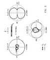
- FIG. 3 is a radiation pattern of the broadband antenna at 510 MHz according to the preferred embodiment of the invention.
- FIG. 4 is a schematic diagram of a current path of the antenna of FIG. 1 in the second resonant mode.
- FIG. 5 is a radiation pattern of the broadband antenna at 740 MHz according to the preferred embodiment of the invention.
- FIG. 6 is a comparison of the measured return loss for the broadband antenna according to the preferred embodiment of the invention and the corresponding conventional dipole antenna.
- FIG. 7 is a schematic diagram of another broadband antenna according to the invention.
- FIG. 8 is a schematic diagram of a third broadband antenna according to the invention.
- the antenna In the broadband antenna of the invention, signals are fed into one short side of the antenna, and the coaxial line used as a feeding circuit oriented along the direction of the radiation conductor. Therefore, the antenna can have a smaller size and thickness, larger bandwidth and more convenience in configuration without reducing antenna performance and attractiveness.
- the broadband antenna of the invention can enlarge operating bandwidth by feeding signals to one short side, and can be applied to receive signals of various frequencies. Any antenna with a dipole antenna structure can use this method of feeding signals to one short side in the antenna to increase the bandwidth and flexibity in configuration no matter which frequency band the antenna is applied in.
- the broadband antenna 100 includes a dielectric substrate 110, a radiation conductor 120 and a feeding gap 130.
- the radiation conductor 120 can be a radiation metal plate or other conductive materials, such as made of indium tin oxide (ITO) and is formed on the dielectric substrate 110 by a method of printing or etching.
- the radiation conductor 120 has a first side 121 and a second side 122 and the first side 121 is adjacent to the second side 122.
- the first side 121 is longer than the second side 122 and the second side 122 has a first feeding point 125 and a second feeding point 126.
- the feeding gap 130 has a first end 131 located at the first side 121 and a second end 132 located at the second side 122.
- the feeding gap divides the radiation conductor 120 into a first sub-radiation conductor 123 and a second sub-radiation conductor 124.
- the first feeding point 125 is located in the area of the first sub-radiation conductor 126 at the second end 132 of the division gap 130 and the second feeding point 126 is located in the area of the second sub-radiation conductor 124 at the second end 132 of the division gap 130.
- the first end 131 of the division gap 130 can be positioned such that the second sub-radiation conductor 124 has a length close to one-third length of the first side 121.
- a radio-frequency (RF) signal is received at the first feeding point 125 and the second feeding point 126 via a coaxial line to excite a first resonant mode and a second resonant mode of the radiation conductor 120.
- the second resonant mode is adjacent to the first resonant mode such that the antenna has one wide resonant mode formed by both the first and second resonant modes.
- the first end 131 of the feeding gap 130 can be positioned such that the length of the second sub-radiation conductor 124 is close to one-fourth wavelength of the second resonant mode.
- the first side 121 is 215 mm long
- the second side 122 is 10 mm long
- the second sub-radiation conductor 124 is 74 mm long for instance.
- a radiation pattern of the broadband antenna 100 at 510 MHz is shown. From FIG. 3, at 510MHz, the antenna can generate a near-omnidirectional radiation pattern in the x-z plane (the horizontal plane); this characteristic is very suitable for broadband antenna application.
- FIG. 4 a schematic diagram of a current path of the antenna 100 of FIG. 1 in the second resonant mode is shown. From FIG. 4, the radiation field generated by the current flowing through the second sub-radiation conductor 124 is cancelled by the radiation field generated by the current flowing through the region of the first sub-radiation conductor 123 located under the second sub-radiation conductor 124.
- the resonant path of the second resonant mode is twice as long as that of the first resonant mode.
- FIG. 5 a radiation pattern of the broadband antenna 100 at 740 MHz according to the preferred embodiment of the invention is shown. From FIG. 5, at 740 MHz, the antenna generates a near-omnidirectioal radiation pattern in the x-z plane (the horizontal plane); this characteristic is very suitable for broadband antenna application.
- the curve 62 is a return loss curve of the broadband antenna 100 in the invention and the curve 61 is a return loss curve of the corres[ondong conventional dipole antenna.
- the point 63 corresponds to the first resonant mode and the point 64 corresponds to the second resonant mode.
- the broadband antenna 100 of the invention has a bandwidth of 470-860 MHz. This bandwidth is much larger than the bandwidth of 500-600 MHz of the corresponding conventional dipole antenna.
- Table 1 performances of a monopole antenna, a conventional dipole antenna and the broadband antenna of the embodiment are shown for comparison.
- the broadband antenna 100 of the invention has a lower VSWR, that is, a lower return loss and a larger bandwidth of 470-860 MHz, without reducing the gain level. This bandwidth is suitable for digital TV operation in many different countries. Furthermore, the broadband antenna 100 of the invention has a smaller area and thickness than the monopole antenna and conventional dipole antenna. Therefore, when the broadband antenna 100 is applied as a digital TV antenna in a car, it is very suitable to be attached to the windshield in front of the driver without affecting the sight of the driver and the car's appearance.
- the feeding gap 130 is step-shaped. However, the shape of the feeding gap 130 is not restricted to just this.
- FIG. 7 a schematic diagram of another broadband antenna according to the invention is shown.
- the feeding gap 730 is line-shaped and divides the radiation conductor 720 into a first sub-radiation conductor 723 and a second sub-radiation conductor 724.
- FIG. 8 a schematic diagram of a third broadband antenna according to the invention is shown.
- the feeding gap 830 is curve-shaped and divides the radiation conductor 820 into a first sub-radiation conductor 823 and a second sub-radiation conductor 824.
- the broadband antenna disclosed by the invention signals are fed into one short side of the antenna, and thus the coaxial line used as a feeding circuit oriented along the direction of the antenna radiation conductor. Therefore, the antenna can have a smaller area and thickness, and a larger bandwidth, which is suitable for antenna application in various bands.
- the broadband antenna of the invention can be attached to the car's windshield and still achieve good performance without affecting the sight of the driver and the car's appearance.
Landscapes
- Details Of Aerials (AREA)
Abstract
Description
- This application incorporates by reference of
Taiwan application Serial No. 95121386, filed June 15, 2006 - The invention relates in general to a broadband antenna, and more particularly to a broadband dipole antenna that is fed at one short side to enlarge the antenna bandwidth.
- Along with technological progress, the need for broadband antennas has been increasing rapidly. For example, people can easily watch digital TV via portable TV products. Digital TV is a television system which converts analog signals to digital signals, and Taiwan now uses a European digital video broadcasting terrestrial (DVB-T) system. The DVB-T system can effectively solve a multi-path interruption problem by using modulation standard signals. The European-specification system constructs a single frequency network (SFN) to increase accessible frequency spectrum resources. In addition, the European TV system has a feature of mobile reception and thus people can watch TV even in a car running at a high speed of 130 km/hr.
- For example, in early periods, antenna technologies of advanced channel estimation and dual antenna reception for distribution and integration were developed in order to improve mobile reception function of the DVB-T receiver disposed in a car. However, these technologies resulted in system complexity, higher hardware costs, and higher antenna power consumption. In the present market, a conventional digital TV antenna used in a car is a monopole antenna. The monopole antenna uses the car shell as a grounded surface, but this greatly affects the appearance of the car and and decreases the car's attractiveness. Also, due to the shielding effects of the car's metal shell, the antenna's ability to receive signals becomes degraded..
- Recently, technology of a dipole antenna for digital TV reception has been developed. Conventionally, owing that signals are fed into the central part of the dipole antenna symmetrically via a coaxial line, the coaxial line will not be parallel to the direction of two arms of the dipole antenna. Therefore, in practical application, the coaxial line needs to be perpendicular to the digital TV antenna, thereby increasing the volume of the antenna. When the digital TV antenna is disposed in a car, it will further affect the aethestic appearance of the car. In addition, due to the narrow width of the antenna's radiation conductor, the antenna's bandwidth may be inadequate.
- It is therefore an object of the invention to provide a broadband antenna. By feeding signals to one short side of the antenna, the coaxial line can be oriented along the direction of a radiation conductor of the antenna. Therefore, the antenna can have a smaller size and thickness, larger bandwidth and more convenience in configuration without reducing antenna performance and attractiveness
- The invention achieves the above-identified object by providing a broadband antenna including a dielectric substrate, a radiation conductor and a feeding gap. The radiation conductor is disposed on the dielectric substrate and has a first side and a second side. The first side is adjacent to the second side, and the first side is longer than the second side. The second side has a first feeding point and a second feeding point. The feed gap has a first end located at the first side and a second end located at the second side. The feed gap divides the radiation conductor into a first sub-radiation conductor and a second sub-radiation conductor. The first feeding point is located on the first sub-radiation conductor and the second feeding point is located on the second sub-radiation conductor.
- Other objects, features, and advantages of the invention will become apparent from the following detailed description of the preferred but non-limiting embodiments. The following description is made with reference to the accompanying drawings.
- FIG. 1 is a schematic diagram of a broadband antenna according to a preferred embodiment of the invention.
- FIG. 2 is a schematic diagram of a current path of the antenna of FIG. 1 in the first resonant mode.
- FIG. 3 is a radiation pattern of the broadband antenna at 510 MHz according to the preferred embodiment of the invention.
- FIG. 4 is a schematic diagram of a current path of the antenna of FIG. 1 in the second resonant mode.
- FIG. 5 is a radiation pattern of the broadband antenna at 740 MHz according to the preferred embodiment of the invention.
- FIG. 6 is a comparison of the measured return loss for the broadband antenna according to the preferred embodiment of the invention and the corresponding conventional dipole antenna.
- FIG. 7 is a schematic diagram of another broadband antenna according to the invention.
- FIG. 8 is a schematic diagram of a third broadband antenna according to the invention.
- In the broadband antenna of the invention, signals are fed into one short side of the antenna, and the coaxial line used as a feeding circuit oriented along the direction of the radiation conductor. Therefore, the antenna can have a smaller size and thickness, larger bandwidth and more convenience in configuration without reducing antenna performance and attractiveness. The broadband antenna of the invention can enlarge operating bandwidth by feeding signals to one short side, and can be applied to receive signals of various frequencies. Any antenna with a dipole antenna structure can use this method of feeding signals to one short side in the antenna to increase the bandwidth and flexibity in configuration no matter which frequency band the antenna is applied in.
- Referring to FIG. 1, a schematic diagram of a broadband antenna according to a preferred embodiment of the invention is shown. The
broadband antenna 100 includes adielectric substrate 110, aradiation conductor 120 and afeeding gap 130. Theradiation conductor 120 can be a radiation metal plate or other conductive materials, such as made of indium tin oxide (ITO) and is formed on thedielectric substrate 110 by a method of printing or etching. Theradiation conductor 120 has afirst side 121 and asecond side 122 and thefirst side 121 is adjacent to thesecond side 122. Thefirst side 121 is longer than thesecond side 122 and thesecond side 122 has afirst feeding point 125 and asecond feeding point 126. - The
feeding gap 130 has afirst end 131 located at thefirst side 121 and asecond end 132 located at thesecond side 122. The feeding gap divides theradiation conductor 120 into afirst sub-radiation conductor 123 and asecond sub-radiation conductor 124. Thefirst feeding point 125 is located in the area of thefirst sub-radiation conductor 126 at thesecond end 132 of thedivision gap 130 and thesecond feeding point 126 is located in the area of thesecond sub-radiation conductor 124 at thesecond end 132 of thedivision gap 130. Besides, in practical application, thefirst end 131 of thedivision gap 130 can be positioned such that thesecond sub-radiation conductor 124 has a length close to one-third length of thefirst side 121. - In the
broadband antenna 100, a radio-frequency (RF) signal is received at thefirst feeding point 125 and thesecond feeding point 126 via a coaxial line to excite a first resonant mode and a second resonant mode of theradiation conductor 120. The second resonant mode is adjacent to the first resonant mode such that the antenna has one wide resonant mode formed by both the first and second resonant modes. Moreover, in practical application, thefirst end 131 of thefeeding gap 130 can be positioned such that the length of thesecond sub-radiation conductor 124 is close to one-fourth wavelength of the second resonant mode. - In the embodiment, the
first side 121 is 215 mm long, thesecond side 122 is 10 mm long and thesecond sub-radiation conductor 124 is 74 mm long for instance. Referring to FIG. 2, a schematic diagram of a current path of theantenna 100 of FIG. 1 in the first resonant mode is shown. From FIG. 2, it can be seen that the radiation field generated by the current flowing through thesecond sub-radiation conductor 124 is cancelled with the radiation field generated by the current flowing through the region of thefirst sub-radiation conductor 123 located under thesecond sub-radiation conductor 124. According to the equation c=f×λ, it can be known that the first resonant mode is excited at about 510MHz. Referring to FIG. 3, a radiation pattern of thebroadband antenna 100 at 510 MHz according to the preferred embodiment of the invention is shown. From FIG. 3, at 510MHz, the antenna can generate a near-omnidirectional radiation pattern in the x-z plane (the horizontal plane); this characteristic is very suitable for broadband antenna application. - Referring to FIG. 4, a schematic diagram of a current path of the
antenna 100 of FIG. 1 in the second resonant mode is shown. From FIG. 4, the radiation field generated by the current flowing through thesecond sub-radiation conductor 124 is cancelled by the radiation field generated by the current flowing through the region of thefirst sub-radiation conductor 123 located under thesecond sub-radiation conductor 124. The resonant path of the second resonant mode is twice as long as that of the first resonant mode. According to the equation c=f×λ, it is known that the second resonant mode is excited at about 740MHz. Referring to FIG. 5, a radiation pattern of thebroadband antenna 100 at 740 MHz according to the preferred embodiment of the invention is shown. From FIG. 5, at 740 MHz, the antenna generates a near-omnidirectioal radiation pattern in the x-z plane (the horizontal plane); this characteristic is very suitable for broadband antenna application. - Referring to FIG. 6, a comparison of the measured return loss for the broadband antenna according to the preferred embodiment of the invention and the corresponding conventional dipole antenna is shown. In FIG. 6, the
curve 62 is a return loss curve of thebroadband antenna 100 in the invention and thecurve 61 is a return loss curve of the corres[ondong conventional dipole antenna. Thepoint 63 corresponds to the first resonant mode and thepoint 64 corresponds to the second resonant mode. Under the condition that the voltage standing wave ratio (VSWR) is 2.5, thebroadband antenna 100 of the invention has a bandwidth of 470-860 MHz. This bandwidth is much larger than the bandwidth of 500-600 MHz of the corresponding conventional dipole antenna. - In Table 1, performances of a monopole antenna, a conventional dipole antenna and the broadband antenna of the embodiment are shown for comparison.
Table 1 Monopole antenna Conventional dipole antenna Broadband Antenna of the embodiment Volume (mm3) 142×30×30 202×49×0.2 215×10×0.4 Bandwidth (MHz) 470∼600 500∼600 470∼860 Gain (dBi) 2 2 2 VSWR <3 <3 <2.5 - From Table 1, the
broadband antenna 100 of the invention has a lower VSWR, that is, a lower return loss and a larger bandwidth of 470-860 MHz, without reducing the gain level. This bandwidth is suitable for digital TV operation in many different countries. Furthermore, thebroadband antenna 100 of the invention has a smaller area and thickness than the monopole antenna and conventional dipole antenna. Therefore, when thebroadband antenna 100 is applied as a digital TV antenna in a car, it is very suitable to be attached to the windshield in front of the driver without affecting the sight of the driver and the car's appearance. In the above-mentionedbroadband antenna 100, thefeeding gap 130 is step-shaped. However, the shape of thefeeding gap 130 is not restricted to just this. As long as thefeeding gap 130 can divide theradiation conductor 120 into thefirst sub-radiation conductor 123 and thesecond sub-radiation conductor 124, it will not depart from the scope of the invention. Referring to FIG. 7, a schematic diagram of another broadband antenna according to the invention is shown. In thebroadband antenna 700, thefeeding gap 730 is line-shaped and divides theradiation conductor 720 into afirst sub-radiation conductor 723 and asecond sub-radiation conductor 724. Referring to FIG. 8, a schematic diagram of a third broadband antenna according to the invention is shown. In thebroadband antenna 800, thefeeding gap 830 is curve-shaped and divides theradiation conductor 820 into afirst sub-radiation conductor 823 and asecond sub-radiation conductor 824. - In the broadband antenna disclosed by the invention, signals are fed into one short side of the antenna, and thus the coaxial line used as a feeding circuit oriented along the direction of the antenna radiation conductor. Therefore, the antenna can have a smaller area and thickness, and a larger bandwidth, which is suitable for antenna application in various bands. In addition, when applied as a digital TV antenna in a car, the broadband antenna of the invention can be attached to the car's windshield and still achieve good performance without affecting the sight of the driver and the car's appearance.
- While the invention has been described by way of example and in terms of three preferred embodiments, it is understood that the invention is not limited thereto. On the contrary, it is intended to cover various modifications and similar arrangements and procedures, and the scope of the appended claims therefore should be accorded the broadest interpretation so as to encompass all such modifications and similar arrangements and procedures.
Claims (11)
- A broadband antenna, comprising:a dielectric substrate;a radiation conductor, disposed on the dielectric substrate, the radiation conductor having a first side and a second side, wherein the first side is adjacent to the second side, the first side is longer than the second side, and the second side has a first feeding point and a second feeding point; anda feeding gap, having a first end located at the first side and a second end located at the second side, wherein the feeding gap divides the radiation conductor into a first sub-radiation conductor and a second sub-radiation conductor;wherein the first feeding point is located on the first sub-radiation conductor and the second feeding point is located on the second sub-radiation conductor.
- The broadband antenna according to claim 1, wherein the radiation conductor is a radiation metal plate.
- The broadband antenna according to claim 1, wherein the radiation conductor is made of indium tin oxide (ITO).
- The broadband antenna according to claim 1, wherein the radiation conductor is formed on the dielectric substrate by a method of printing or etching.
- The broadband antenna according to claim 1, wherein the feeding gap is step-shaped.
- The broadband antenna according to claim 1, wherein the feeding gap is line-shaped.
- The broadband antenna according to claim 1, wherein the feeding gap is curve-shaped.
- The broadband antenna according to claim 1, wherein the first end of the feeding gap is located at the first side such that the length of the second sub-radiation conductor is close to one-third of the length of the first side.
- The broadband antenna according to claim 1, wherein a radio-frequency (RF) signal is received at the first and second feeding points to generate a first and a second resonant mode of the radiation conductor, the first resonant mode being adjacent to the second resonant mode, such that the antenna has one wide resonant mode formed by both the first and second resonant modes.
- The broadband antenna according to claim 9, wherein the RF signal is transmitted via a coaxial line.
- The broadband antenna according to claim 9, wherein the first end of the feeding gap is located at the first side such that the length of the second sub-radiation conductor is close to one-fourth wavelength of the second resonant mode.
Priority Applications (2)
| Application Number | Priority Date | Filing Date | Title |
|---|---|---|---|
| EP06017459A EP1892800B1 (en) | 2006-08-22 | 2006-08-22 | Broadband antenna |
| DE602006019089T DE602006019089D1 (en) | 2006-08-22 | 2006-08-22 | Broadband antenna |
Applications Claiming Priority (1)
| Application Number | Priority Date | Filing Date | Title |
|---|---|---|---|
| EP06017459A EP1892800B1 (en) | 2006-08-22 | 2006-08-22 | Broadband antenna |
Publications (2)
| Publication Number | Publication Date |
|---|---|
| EP1892800A1 true EP1892800A1 (en) | 2008-02-27 |
| EP1892800B1 EP1892800B1 (en) | 2010-12-22 |
Family
ID=37625933
Family Applications (1)
| Application Number | Title | Priority Date | Filing Date |
|---|---|---|---|
| EP06017459A Active EP1892800B1 (en) | 2006-08-22 | 2006-08-22 | Broadband antenna |
Country Status (2)
| Country | Link |
|---|---|
| EP (1) | EP1892800B1 (en) |
| DE (1) | DE602006019089D1 (en) |
Citations (3)
| Publication number | Priority date | Publication date | Assignee | Title |
|---|---|---|---|---|
| GB2029112A (en) * | 1978-06-08 | 1980-03-12 | Murphy A | Television aerial |
| WO2004077610A1 (en) * | 2003-02-28 | 2004-09-10 | Research In Motion Limited | Multiple-element antenna with wide-band antenna element |
| US20040178957A1 (en) * | 2003-03-14 | 2004-09-16 | Kuang-Yuan Chang | Multi-band printed monopole antenna |
-
2006
- 2006-08-22 EP EP06017459A patent/EP1892800B1/en active Active
- 2006-08-22 DE DE602006019089T patent/DE602006019089D1/en active Active
Patent Citations (3)
| Publication number | Priority date | Publication date | Assignee | Title |
|---|---|---|---|---|
| GB2029112A (en) * | 1978-06-08 | 1980-03-12 | Murphy A | Television aerial |
| WO2004077610A1 (en) * | 2003-02-28 | 2004-09-10 | Research In Motion Limited | Multiple-element antenna with wide-band antenna element |
| US20040178957A1 (en) * | 2003-03-14 | 2004-09-16 | Kuang-Yuan Chang | Multi-band printed monopole antenna |
Non-Patent Citations (1)
| Title |
|---|
| ZI DONG LIU ET AL: "Dual-Frequency Planar Inverted-F Antenna", IEEE TRANSACTIONS ON ANTENNAS AND PROPAGATION, IEEE SERVICE CENTER, PISCATAWAY, NJ, US, vol. 45, no. 10, October 1997 (1997-10-01), XP011003077, ISSN: 0018-926X * |
Also Published As
| Publication number | Publication date |
|---|---|
| DE602006019089D1 (en) | 2011-02-03 |
| EP1892800B1 (en) | 2010-12-22 |
Similar Documents
| Publication | Publication Date | Title |
|---|---|---|
| US6326927B1 (en) | Capacitively-tuned broadband antenna structure | |
| US20030063031A1 (en) | Broadband circularly polarized patch antenna | |
| EP3101728B1 (en) | Glass antenna for vehicle and rear window glass with glass antenna for vehicle | |
| US20030052824A1 (en) | Internal multi-band antenna with improved radiation efficiency | |
| US20040263396A1 (en) | Internal antenna of mobile communication terminal | |
| GB2402552A (en) | Broadband dielectric resonator antenna system | |
| EP2458672B1 (en) | Vehicular antenna apparatus and window glass | |
| US20120182187A1 (en) | Thin antenna and an electronic device having the thin antenna | |
| EP2495807B1 (en) | Multiband antenna | |
| US7586456B2 (en) | Broadband antenna | |
| US6819288B2 (en) | Singular feed broadband aperture coupled circularly polarized patch antenna | |
| US7567210B2 (en) | Small size ultra-wideband antenna | |
| EP1892800B1 (en) | Broadband antenna | |
| US20060290582A1 (en) | Tunable antenna control unit | |
| CN101110496B (en) | broadband antenna | |
| Bai et al. | A broadband high gain microstrip Yagi antenna array for mm-wave communication systems | |
| JP2005229140A (en) | Antenna for vehicle | |
| KR100861882B1 (en) | Multiband antenna | |
| JPH07115313A (en) | High frequency glass antenna for automobiles | |
| CN108155469A (en) | A kind of Broadband Circular Polarization Microstrip Antenna of coplanar wave guide feedback | |
| WO2012049918A1 (en) | Antenna | |
| US7808431B2 (en) | Antenna apparatus capable of directivity control | |
| KR20090132721A (en) | Multiband Internal Antenna for Laptop-Top Computers | |
| JPH0797722B2 (en) | Car TV antenna | |
| Niyamanon et al. | Wideband dual-arm capacitively coupled patch antenna for tablet/laptop applications |
Legal Events
| Date | Code | Title | Description |
|---|---|---|---|
| PUAI | Public reference made under article 153(3) epc to a published international application that has entered the european phase |
Free format text: ORIGINAL CODE: 0009012 |
|
| AK | Designated contracting states |
Kind code of ref document: A1 Designated state(s): AT BE BG CH CY CZ DE DK EE ES FI FR GB GR HU IE IS IT LI LT LU LV MC NL PL PT RO SE SI SK TR |
|
| AX | Request for extension of the european patent |
Extension state: AL BA HR MK YU |
|
| 17P | Request for examination filed |
Effective date: 20080819 |
|
| AKX | Designation fees paid |
Designated state(s): DE FR GB |
|
| 17Q | First examination report despatched |
Effective date: 20090310 |
|
| GRAP | Despatch of communication of intention to grant a patent |
Free format text: ORIGINAL CODE: EPIDOSNIGR1 |
|
| GRAS | Grant fee paid |
Free format text: ORIGINAL CODE: EPIDOSNIGR3 |
|
| GRAA | (expected) grant |
Free format text: ORIGINAL CODE: 0009210 |
|
| AK | Designated contracting states |
Kind code of ref document: B1 Designated state(s): DE FR GB |
|
| REG | Reference to a national code |
Ref country code: GB Ref legal event code: FG4D |
|
| REF | Corresponds to: |
Ref document number: 602006019089 Country of ref document: DE Date of ref document: 20110203 Kind code of ref document: P |
|
| REG | Reference to a national code |
Ref country code: DE Ref legal event code: R096 Ref document number: 602006019089 Country of ref document: DE Effective date: 20110203 |
|
| PLBE | No opposition filed within time limit |
Free format text: ORIGINAL CODE: 0009261 |
|
| STAA | Information on the status of an ep patent application or granted ep patent |
Free format text: STATUS: NO OPPOSITION FILED WITHIN TIME LIMIT |
|
| 26N | No opposition filed |
Effective date: 20110923 |
|
| REG | Reference to a national code |
Ref country code: DE Ref legal event code: R097 Ref document number: 602006019089 Country of ref document: DE Effective date: 20110923 |
|
| REG | Reference to a national code |
Ref country code: FR Ref legal event code: PLFP Year of fee payment: 11 |
|
| REG | Reference to a national code |
Ref country code: FR Ref legal event code: PLFP Year of fee payment: 12 |
|
| REG | Reference to a national code |
Ref country code: FR Ref legal event code: PLFP Year of fee payment: 13 |
|
| PGFP | Annual fee paid to national office [announced via postgrant information from national office to epo] |
Ref country code: DE Payment date: 20250827 Year of fee payment: 20 |
|
| PGFP | Annual fee paid to national office [announced via postgrant information from national office to epo] |
Ref country code: GB Payment date: 20250827 Year of fee payment: 20 |
|
| PGFP | Annual fee paid to national office [announced via postgrant information from national office to epo] |
Ref country code: FR Payment date: 20250825 Year of fee payment: 20 |