EP1892180A1 - Variable toe angle control system for a vehicle - Google Patents
Variable toe angle control system for a vehicle Download PDFInfo
- Publication number
- EP1892180A1 EP1892180A1 EP07011263A EP07011263A EP1892180A1 EP 1892180 A1 EP1892180 A1 EP 1892180A1 EP 07011263 A EP07011263 A EP 07011263A EP 07011263 A EP07011263 A EP 07011263A EP 1892180 A1 EP1892180 A1 EP 1892180A1
- Authority
- EP
- European Patent Office
- Prior art keywords
- actuators
- toe
- wheels
- vehicle
- angles
- Prior art date
- Legal status (The legal status is an assumption and is not a legal conclusion. Google has not performed a legal analysis and makes no representation as to the accuracy of the status listed.)
- Granted
Links
Images


Classifications
-
- B—PERFORMING OPERATIONS; TRANSPORTING
- B62—LAND VEHICLES FOR TRAVELLING OTHERWISE THAN ON RAILS
- B62D—MOTOR VEHICLES; TRAILERS
- B62D17/00—Means on vehicles for adjusting camber, castor, or toe-in
-
- B—PERFORMING OPERATIONS; TRANSPORTING
- B60—VEHICLES IN GENERAL
- B60G—VEHICLE SUSPENSION ARRANGEMENTS
- B60G17/00—Resilient suspensions having means for adjusting the spring or vibration-damper characteristics, for regulating the distance between a supporting surface and a sprung part of vehicle or for locking suspension during use to meet varying vehicular or surface conditions, e.g. due to speed or load
- B60G17/015—Resilient suspensions having means for adjusting the spring or vibration-damper characteristics, for regulating the distance between a supporting surface and a sprung part of vehicle or for locking suspension during use to meet varying vehicular or surface conditions, e.g. due to speed or load the regulating means comprising electric or electronic elements
- B60G17/016—Resilient suspensions having means for adjusting the spring or vibration-damper characteristics, for regulating the distance between a supporting surface and a sprung part of vehicle or for locking suspension during use to meet varying vehicular or surface conditions, e.g. due to speed or load the regulating means comprising electric or electronic elements characterised by their responsiveness, when the vehicle is travelling, to specific motion, a specific condition, or driver input
- B60G17/0164—Resilient suspensions having means for adjusting the spring or vibration-damper characteristics, for regulating the distance between a supporting surface and a sprung part of vehicle or for locking suspension during use to meet varying vehicular or surface conditions, e.g. due to speed or load the regulating means comprising electric or electronic elements characterised by their responsiveness, when the vehicle is travelling, to specific motion, a specific condition, or driver input mainly during accelerating or braking
-
- B—PERFORMING OPERATIONS; TRANSPORTING
- B60—VEHICLES IN GENERAL
- B60G—VEHICLE SUSPENSION ARRANGEMENTS
- B60G7/00—Pivoted suspension arms; Accessories thereof
- B60G7/006—Attaching arms to sprung or unsprung part of vehicle, characterised by comprising attachment means controlled by an external actuator, e.g. a fluid or electrical motor
-
- B—PERFORMING OPERATIONS; TRANSPORTING
- B62—LAND VEHICLES FOR TRAVELLING OTHERWISE THAN ON RAILS
- B62D—MOTOR VEHICLES; TRAILERS
- B62D7/00—Steering linkage; Stub axles or their mountings
- B62D7/06—Steering linkage; Stub axles or their mountings for individually-pivoted wheels, e.g. on king-pins
- B62D7/14—Steering linkage; Stub axles or their mountings for individually-pivoted wheels, e.g. on king-pins the pivotal axes being situated in more than one plane transverse to the longitudinal centre line of the vehicle, e.g. all-wheel steering
- B62D7/146—Steering linkage; Stub axles or their mountings for individually-pivoted wheels, e.g. on king-pins the pivotal axes being situated in more than one plane transverse to the longitudinal centre line of the vehicle, e.g. all-wheel steering characterised by comprising means for steering by acting on the suspension system, e.g. on the mountings of the suspension arms
-
- B—PERFORMING OPERATIONS; TRANSPORTING
- B60—VEHICLES IN GENERAL
- B60G—VEHICLE SUSPENSION ARRANGEMENTS
- B60G2200/00—Indexing codes relating to suspension types
- B60G2200/40—Indexing codes relating to the wheels in the suspensions
- B60G2200/462—Toe-in/out
-
- B—PERFORMING OPERATIONS; TRANSPORTING
- B60—VEHICLES IN GENERAL
- B60G—VEHICLE SUSPENSION ARRANGEMENTS
- B60G2400/00—Indexing codes relating to detected, measured or calculated conditions or factors
- B60G2400/10—Acceleration; Deceleration
- B60G2400/106—Acceleration; Deceleration longitudinal with regard to vehicle, e.g. braking
-
- B—PERFORMING OPERATIONS; TRANSPORTING
- B60—VEHICLES IN GENERAL
- B60G—VEHICLE SUSPENSION ARRANGEMENTS
- B60G2400/00—Indexing codes relating to detected, measured or calculated conditions or factors
- B60G2400/30—Propulsion unit conditions
- B60G2400/33—Throttle position
-
- B—PERFORMING OPERATIONS; TRANSPORTING
- B60—VEHICLES IN GENERAL
- B60G—VEHICLE SUSPENSION ARRANGEMENTS
- B60G2400/00—Indexing codes relating to detected, measured or calculated conditions or factors
- B60G2400/30—Propulsion unit conditions
- B60G2400/39—Brake pedal position
-
- B—PERFORMING OPERATIONS; TRANSPORTING
- B60—VEHICLES IN GENERAL
- B60G—VEHICLE SUSPENSION ARRANGEMENTS
- B60G2400/00—Indexing codes relating to detected, measured or calculated conditions or factors
- B60G2400/90—Other conditions or factors
- B60G2400/98—Stabiliser movement
-
- B—PERFORMING OPERATIONS; TRANSPORTING
- B60—VEHICLES IN GENERAL
- B60G—VEHICLE SUSPENSION ARRANGEMENTS
- B60G2800/00—Indexing codes relating to the type of movement or to the condition of the vehicle and to the end result to be achieved by the control action
- B60G2800/01—Attitude or posture control
- B60G2800/012—Rolling condition
Definitions
- the present invention relates to a variable toe angle control system for a vehicle that can individually vary the toe angles of the right and left wheels.
- a linear actuator such as a hydraulic cylinder between a vehicle body end of a lateral link or a trailing arm of a wheel suspension unit for supporting each rear wheel and the vehicle body, and to individually control the toe angles of the right and left wheels by extending or retracting the corresponding linear actuators (see Japanese patent publication No. 8-25482 and Japanese patent laid open publication No. 9-30438 ).
- a fail-safe mechanism is required so that the vehicle may be able to continue to travel without any inconvenience even in case of a failure of the system.
- the hydraulic actuator described in Japanese patent publication No. 8-25482 is provided with a piston rod that is resiliently urged by a spring member in the direction to retract the piston rod in such a manner that the toe angle is automatically restored to a zero angle when the hydraulic pressure is lost.
- the actuator When the actuator is based on the use of a threaded rod, and the lead angle of the thread is selected in such a manner that the actuator remains immobile owing to the friction, because the linear displacement of the actuator is impossible without turning the threaded rod, there is some difficulty in providing a fail-safe mechanism.
- a primary object of the present invention is to provide a variable toe angle control system for a vehicle that can be incorporated with a fail-safe mechanism without complicating the structure, increasing the size of the system or requiring any additional power requirements.
- a second object of the present invention is to provide a method for controlling the toe angle of a vehicle that allows a fail-safe mechanism to be incorporated in the hardware structure without complicating the structure, increasing the size of the system or requiring any additional power requirements.
- a variable toe angle control system for a vehicle, comprising: a pair of actuators for individually varying toe angles of a right and left wheel; a pair of sensors for individually detecting the toe angles of the right and left wheels; and a control unit for determining a target value for each of the right and left wheels according to operating conditions of the vehicle and supplying a control signal to each of the actuators according to an output of the corresponding sensor and the corresponding target value; wherein the control unit is configured to detect a fault of the system and actuate at least one of the actuators to make the toe angles of the two wheels agree with each other when a fault is detected in a part of the system.
- the present invention also provides a method for controlling toe angles of a vehicle in a variable toe angle control system, comprising: preparing a pair of actuators for individually varying toe angles of a right and left wheel; preparing a pair of sensors for individually detecting the toe angles of the right and left wheels; determining a target value for each of the right and left wheels according to operating conditions of the vehicle; supplying a control signal to each of the actuators according to an output of the corresponding sensor and the corresponding target value; detecting a fault of the system; and actuating at least one of the actuators to make the toe angles of the two wheels agree with each other when a fault is detected in a part of the system.
- the variable toe angle control system becomes unable to provide a normal control function, there is no-need for a return spring device that would be otherwise required to force the wheels to neutral positions and to ensure the capability of the vehicle to travel along a straight path so that the structure can be made simple and the power source may consist of a compact structure owing to the absence of the need to have the actuator produce a force to oppose the spring force of the return spring device for forcing the wheels to the neutral positions.
- the actuator for the other wheel may be actuated so as to make the toe angles of the two wheels equal to each other.
- both the actuators may be actuated until the actuators reach positions corresponding to stoppers that may be provided in suitable locations.
- both the actuators may be actuated until the actuators reach positions corresponding to prescribed reference toe positions.
- FIG. 1 shows an outline of a vehicle to which the present invention is applied.
- the vehicle V comprises a front wheel steering device 3 for directly steering a right and left front wheel 2L and 2R according to a steering angle of a steering wheel 1, a right and left actuator 5L and 5R for individually changing the toe angles of a right and left rear wheel 4L and 4R by varying the lengths of parts, such as laterals links, of rear wheel suspension units supporting the right and left rear wheels 4L and 4R, respectively, a right and left toe angle sensor 6L and 6R for individually detecting the toe angles of the right and left rear wheels 4L and 4R, an accelerator sensor 7 for detecting a fore-and-aft acceleration acting upon the vehicle body to use it as a reference signal for determining a target control value in the variable toe angle control, a steering angle sensor 8 for detecting the steering angle of the steering wheel 1, and a control unit 9 for controlling the displacements of the actuators 5L and 5R according to the outputs of the various sensors.
- Each actuator 5L, 5R may consist of a rotary motion / linear motion converter combining an electric motor fitted with a reduction gear and a thread mechanism, a cylinder device that linearly actuates a piston rod by using hydraulic pressure or any other known linear actuator.
- Each toe angle sensor 6L, 6R may consist of a potentiometer or any other known displacement sensor, but preferably consists of an electromagnetic sensor or other non-contact sensor for an improved durability.
- the toe-in and toe-out of the rear wheels 4L and 4R can be freely controlled under a prescribed condition by simultaneously actuating the right and left actuators 5L and 5R in a symmetric manner. If one of the right and left actuators 5L and 5R is extended while the other is retracted, the two rear wheels 4L and 4R may be steered either in the right or left direction.
- the target value for each rear wheel 4L, 4R can be obtained from a map of optimum toe angle with respect to such running conditions as the front wheel steering angle and fore-and-aft acceleration.
- an optimum torque that should be produced from the corresponding actuator 5L, 5R is computed from the deviation of the actual toe angle from a target toe angle, and an electric motor is duty controlled so as to produce the optimum torque through a current feedback.
- FIG. 2 shows a control flow of the system of the present invention.
- step 1 it is determined if the overall system is operating normally (step 1). If the overall system is operating normally (Yes), a normal variable toe angle control is executed as described above (step 2). If an abnormal operation of the overall system is detected (No), it is determined if-this abnormal operation is such that the basic data, such as front wheel steering angle and acceleration, for setting a control target value for the rear wheels is not available or the intelligent part of the variable toe angle control system itself is faulty (step 3). If the fault is in the intelligent part of the system, and not in drive system or the sensing system of the variable toe angle control system (Yes), a standard abnormal mode is executed (step 4).
- variable toe angle control is terminated, and the two actuators are actuated toward a prescribed position such as a zero toe angle position ( Figure 3).
- the vehicle is then able to operate in a same manner as a conventional vehicle, however, without any toe angle control.
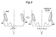
- step 5 it is determined whether the fault is in the drive system of either one of the actuators 5L and 5R or either one of the toe angle sensors 6L and 6R (step 5). If the drive systems of the actuators 5L and 5R are in good order but at least one of the toe angle sensors 6L and 6R is found to be faulty (Yes), a sensor system abnormal mode is executed (step 6). In this case, the actuators 5L and 5R can operate in a normal fashion, but the actuator corresponding to the faulty toe angle sensor is unable to determine its own position. Therefore, the two actuators are both actuated to safe positions (with some toe-in) defined by mechanical stoppers by using an open loop so that the vehicle is allowed to travel in a stable manner ( Figure 4). _
- Any abnormal condition in the toe angle sensors 6L and 6R can be detected when an abrupt change in the output is detected or when the output deviates from a normal range for more than a prescribed time period.
- a redundant sensor having two outputs can be used. In this case, a fault is detected if a prescribed relationship fails to be hold between the two outputs.
- a drive system abnormal mode is executed (step 7).
- the normal actuator is actuated to a position which is symmetric to the position of the failed actuator ( Figure 5).
- An abnormal condition of any of the drive systems can be determined from an abnormal relationship between the duty ratio (or voltage) of the electric power applied to the electric motor and the feedback current (or the motor torque) or from an abnormal supply voltage to the electric motor.
- the abnormal toe angle is changed to a target position at a speed appropriate to the nature of the component that has failed or the running condition of the vehicle as quickly as possible without causing any discomfort to the vehicle operator.
- the present invention allows a fail-safe system for a variable toe angle control system at a relatively low cost.
- the toe angles of the right and left wheels may be controlled to asymmetric values such as to change the oversteer / understeer tendency of the vehicle, or as to enable the vehicle to travel along a straight path when the vehicle is traveling on a split- ⁇ road surface.
- variable toe angle control system for a vehicle that can be incorporated with a fail-safe mechanism without complicating the structure, increasing the size of the system or requiring any additional power requirements.
- at least one of toe-angle actuators (5L, 5R) is actuated to make the toe angles of the two wheels (4L, 4R) agree with each other when a fault is detected in a part of the system.
- the actuator for the other wheel is actuated so as to make the toe angles of the two wheels equal to each other.
- the actuators both actuated until the actuators reach positions corresponding to the stoppers.
- the actuators both actuated until the actuators reach positions corresponding to prescribed reference toe positions.
Landscapes
- Engineering & Computer Science (AREA)
- Mechanical Engineering (AREA)
- Chemical & Material Sciences (AREA)
- Combustion & Propulsion (AREA)
- Transportation (AREA)
- Vehicle Body Suspensions (AREA)
- Power Steering Mechanism (AREA)
Abstract
Description
- The present invention relates to a variable toe angle control system for a vehicle that can individually vary the toe angles of the right and left wheels.
- It is known to provide a linear actuator such as a hydraulic cylinder between a vehicle body end of a lateral link or a trailing arm of a wheel suspension unit for supporting each rear wheel and the vehicle body, and to individually control the toe angles of the right and left wheels by extending or retracting the corresponding linear actuators (see
Japanese patent publication No. 8-25482 Japanese patent laid open publication No. 9-30438 - In such a system, a fail-safe mechanism is required so that the vehicle may be able to continue to travel without any inconvenience even in case of a failure of the system. For instance, the hydraulic actuator described in
Japanese patent publication No. 8-25482 - However, according to this prior art, when extending the piston rod under a normal condition, the hydraulic pressure is required to be high enough to oppose the spring force which is capable of maintaining the toe angle against the reaction from the road surface in case of a failure of the actuator so that the actuator and hydraulic pressure generator are required to be relatively large in size.
- When the actuator is based on the use of a threaded rod, and the lead angle of the thread is selected in such a manner that the actuator remains immobile owing to the friction, because the linear displacement of the actuator is impossible without turning the threaded rod, there is some difficulty in providing a fail-safe mechanism.
- In view of such problems of the prior art, a primary object of the present invention is to provide a variable toe angle control system for a vehicle that can be incorporated with a fail-safe mechanism without complicating the structure, increasing the size of the system or requiring any additional power requirements.
- A second object of the present invention is to provide a method for controlling the toe angle of a vehicle that allows a fail-safe mechanism to be incorporated in the hardware structure without complicating the structure, increasing the size of the system or requiring any additional power requirements.
- According to the present invention, such objects can be accomplished by providing a variable toe angle control system for a vehicle, comprising: a pair of actuators for individually varying toe angles of a right and left wheel; a pair of sensors for individually detecting the toe angles of the right and left wheels; and a control unit for determining a target value for each of the right and left wheels according to operating conditions of the vehicle and supplying a control signal to each of the actuators according to an output of the corresponding sensor and the corresponding target value; wherein the control unit is configured to detect a fault of the system and actuate at least one of the actuators to make the toe angles of the two wheels agree with each other when a fault is detected in a part of the system.
- The present invention also provides a method for controlling toe angles of a vehicle in a variable toe angle control system, comprising: preparing a pair of actuators for individually varying toe angles of a right and left wheel; preparing a pair of sensors for individually detecting the toe angles of the right and left wheels; determining a target value for each of the right and left wheels according to operating conditions of the vehicle; supplying a control signal to each of the actuators according to an output of the corresponding sensor and the corresponding target value; detecting a fault of the system; and actuating at least one of the actuators to make the toe angles of the two wheels agree with each other when a fault is detected in a part of the system.
- Thereby, in any situation, the toe angles of the two wheels are made to agree with each other, although the toe angle control is disabled, the vehicle can continue to travel without incurring any major inconveniences. Therefore, according to the present invention, even when the variable toe angle control system becomes unable to provide a normal control function, there is no-need for a return spring device that would be otherwise required to force the wheels to neutral positions and to ensure the capability of the vehicle to travel along a straight path so that the structure can be made simple and the power source may consist of a compact structure owing to the absence of the need to have the actuator produce a force to oppose the spring force of the return spring device for forcing the wheels to the neutral positions.
- When one of the wheels has become fixed in position without regard to the control signal supplied to the corresponding actuator, the actuator for the other wheel may be actuated so as to make the toe angles of the two wheels equal to each other. When at least one of the sensors is found to be faulty, both the actuators may be actuated until the actuators reach positions corresponding to stoppers that may be provided in suitable locations. When information for determining target values of the toe angles of the right and left wheels is found to be faulty, both the actuators may be actuated until the actuators reach positions corresponding to prescribed reference toe positions.
- Now the present invention is described in the following with reference to the appended drawings, in which:
- Figure 1 is a schematic view of a vehicle to which the present invention is applied;
- Figure 2 is a flowchart of the control process of the system of the present invention;
- Figure 3 is a diagram showing the mode of operation in the standar abnormal mode;
- Figure 4 is a diagram showing the mode of operation in the sensor system abnormal mode; and
- Figure 5 is a diagram showing the mode of operation in the drive system abnormal mode.
- Figure 1 shows an outline of a vehicle to which the present invention is applied. The vehicle V comprises a front
wheel steering device 3 for directly steering a right and leftfront wheel steering wheel 1, a right andleft actuator rear wheel rear wheels toe angle sensor rear wheels steering wheel 1, and a control unit 9 for controlling the displacements of theactuators corresponding wheels - Each
actuator toe angle sensor - According to such a variable toe angle control system, the toe-in and toe-out of the
rear wheels left actuators left actuators rear wheels - The target value for each
rear wheel toe angle sensor corresponding actuator - Figure 2 shows a control flow of the system of the present invention. First of all, it is determined if the overall system is operating normally (step 1). If the overall system is operating normally (Yes), a normal variable toe angle control is executed as described above (step 2). If an abnormal operation of the overall system is detected (No), it is determined if-this abnormal operation is such that the basic data, such as front wheel steering angle and acceleration, for setting a control target value for the rear wheels is not available or the intelligent part of the variable toe angle control system itself is faulty (step 3). If the fault is in the intelligent part of the system, and not in drive system or the sensing system of the variable toe angle control system (Yes), a standard abnormal mode is executed (step 4).
- In this case, because the proper toe angle cannot be computed although the
actuators - An abnormal condition other than that of the intelligent part of the variable toe angle control system can be determined as a failure to achieve a prescribed relationship between the speed difference ΔV between the two
rear wheels rear wheels - If the variable toe angle control system is found to be faulty in step 3 (No), it is determined whether the fault is in the drive system of either one of the
actuators toe angle sensors actuators toe angle sensors actuators - Any abnormal condition in the
toe angle sensors - If a fault is detected in any of the drive systems such as one of the actuators (No), a drive system abnormal mode is executed (step 7). In this case, because the
toe angle sensors actuators - An abnormal condition of any of the drive systems can be determined from an abnormal relationship between the duty ratio (or voltage) of the electric power applied to the electric motor and the feedback current (or the motor torque) or from an abnormal supply voltage to the electric motor.
- The abnormal toe angle is changed to a target position at a speed appropriate to the nature of the component that has failed or the running condition of the vehicle as quickly as possible without causing any discomfort to the vehicle operator.
- Thus, the present invention allows a fail-safe system for a variable toe angle control system at a relatively low cost.
- In the present invention, without regard to whether a fault is detected in any of the drive systems or in any of the sensor systems, when changing the toe angle of the normal side is changed in relation to the toe angle of the faulty side which is known, the toe angles of the right and left wheels may be controlled to asymmetric values such as to change the oversteer / understeer tendency of the vehicle, or as to enable the vehicle to travel along a straight path when the vehicle is traveling on a split-µ road surface.
- Although the present invention has been described in terms of a preferred embodiment thereof, it is obvious to a person skilled in the art that various alterations and modifications are possible without departing from the scope of the present invention which is set forth in the appended claims. For instance, the foregoing embodiment was directed to an application to rear wheels of a vehicle, but may also be applied to front wheels with slight modification to the embodiment which is obvious to a person skilled in the art.
- The contents of the original Japanese patent application on which the Paris Convention priority claim is made for the present application are incorporated in this application by reference.
- Provided is a variable toe angle control system for a vehicle that can be incorporated with a fail-safe mechanism without complicating the structure, increasing the size of the system or requiring any additional power requirements. When a fault of the system is detected, at least one of toe-angle actuators (5L, 5R) is actuated to make the toe angles of the two wheels (4L, 4R) agree with each other when a fault is detected in a part of the system. When one of the wheels has become fixed in position without regard to the control signal supplied to the corresponding actuator, the actuator for the other wheel is actuated so as to make the toe angles of the two wheels equal to each other. When at least one of toe-angle sensors (6L, 6R) is found to be faulty, the actuators both actuated until the actuators reach positions corresponding to the stoppers. When information for determining target values of the toe angles of the right and left wheels is found to be faulty, the actuators both actuated until the actuators reach positions corresponding to prescribed reference toe positions.
Claims (8)
- A variable toe angle control system for a vehicle, comprising:a pair of actuators for individually varying toe angles of a right and left wheel;a pair of sensors for individually detecting the toe angles of the right and left wheels; anda control unit for determining a target value for each of the right and left wheels according to operating conditions of the vehicle and supplying a control signal to each of the actuators according to an output of the corresponding sensor and the corresponding target value;wherein the control unit is configured to detect a fault of the system and actuate at least one of the actuators to make the toe angles of the two-wheels agree with each other when a fault is detected in a part of the system.
- The variable toe angle control system according to claim 1, wherein when one of the wheels becomes fixed in position without regard to the control signal supplied to the corresponding actuator, the control unit actuates the actuator for the other wheel so as to make the toe angles of the two wheels equal to each other.
- The variable toe angle control system according to claim 1, further comprising a stopper for each of the right and left wheels, wherein when at least one of the sensors is found to be faulty, the two actuators are actuated until the actuators reach positions corresponding to the stoppers.
- The variable toe angle control system according to claim 1, wherein when information for determining target values of the toe angles of the right and left wheels is found to be faulty, the two actuators are actuated until the actuators reach positions corresponding to prescribed reference toe positions.
- A method for controlling toe angles of a vehicle in a variable toe angle control system, comprising:preparing a pair of actuators for individually varying toe angles of a right and left wheel;preparing a pair of sensors for individually detecting the toe angles of the right and left wheels;determining a target value for each of the right and left wheels according to operating conditions of the vehicle;supplying a control signal to each of the actuators according to an output of the corresponding sensor and the corresponding target value;detecting a fault of the system; andactuating at least one of the actuators to make the toe angles of the two wheels agree with each other when a fault is detected in a part of the system.
- The method according to claim 5, further comprising, when one of the wheels has become fixed in position without regard to the control signal supplied to the corresponding actuator, actuating the actuator for the other wheel so as to make the toe angles of the two wheels equal to each other.
- The method according to claim 5, further comprising preparing a stopper for each of the right and left wheels, and, when at least one of the sensors is found to be faulty, actuating both the actuators until the actuators reach positions corresponding to the stoppers.
- The method according to claim 5, further comprising, when information for determining target values of the toe angles of the right and left wheels is found to be faulty, actuating both the actuators until the actuators reach positions corresponding to prescribed reference toe positions.
Applications Claiming Priority (2)
| Application Number | Priority Date | Filing Date | Title |
|---|---|---|---|
| JP2006228552A JP4448838B2 (en) | 2006-08-25 | 2006-08-25 | Vehicle toe angle variable control device |
| JP2006231543A JP2008055921A (en) | 2006-08-29 | 2006-08-29 | Vehicle rear wheel toe angle variable control device |
Publications (2)
| Publication Number | Publication Date |
|---|---|
| EP1892180A1 true EP1892180A1 (en) | 2008-02-27 |
| EP1892180B1 EP1892180B1 (en) | 2008-08-20 |
Family
ID=38445695
Family Applications (2)
| Application Number | Title | Priority Date | Filing Date |
|---|---|---|---|
| EP20070011263 Not-in-force EP1892180B1 (en) | 2006-08-25 | 2007-06-08 | Variable toe angle control system for a vehicle |
| EP20070011262 Not-in-force EP1892179B1 (en) | 2006-08-25 | 2007-06-08 | Variable rear wheel toe angle control system for a vehicle |
Family Applications After (1)
| Application Number | Title | Priority Date | Filing Date |
|---|---|---|---|
| EP20070011262 Not-in-force EP1892179B1 (en) | 2006-08-25 | 2007-06-08 | Variable rear wheel toe angle control system for a vehicle |
Country Status (2)
| Country | Link |
|---|---|
| EP (2) | EP1892180B1 (en) |
| DE (2) | DE602007000590D1 (en) |
Cited By (2)
| Publication number | Priority date | Publication date | Assignee | Title |
|---|---|---|---|---|
| EP2078663A1 (en) * | 2008-01-08 | 2009-07-15 | Honda Motor Co., Ltd. | Vehicle with a variable rear toe angle |
| WO2012010277A1 (en) * | 2010-07-23 | 2012-01-26 | Audi Ag | Method for operating a mechatronic chassis device of a motor vehicle |
Families Citing this family (6)
| Publication number | Priority date | Publication date | Assignee | Title |
|---|---|---|---|---|
| FR2941666B1 (en) * | 2009-02-03 | 2012-07-20 | Peugeot Citroen Automobiles Sa | METHOD FOR CONTROLLING REAR WHEEL BRAKING OF A MOTOR VEHICLE. |
| JP5432984B2 (en) | 2009-03-10 | 2014-03-05 | 本田技研工業株式会社 | Rear wheel toe angle control device for vehicle |
| CN102666260B (en) * | 2009-12-25 | 2015-03-25 | 本田技研工业株式会社 | Rear-wheel toe-angle control device for a vehicle |
| DE102015011621B4 (en) * | 2015-09-05 | 2019-04-25 | Audi Ag | Understeer assistant and method for controlling a cornering behavior of a vehicle |
| CN105235467B (en) * | 2015-09-28 | 2017-09-26 | 北京理工大学 | Unmanned motor platform is turned to based on the rocker arm suspension formula speed difference being driven in elbow |
| DE102022112086B4 (en) | 2022-05-13 | 2024-05-02 | Hyundai Mobis Co., Ltd. | METHOD AND DEVICE FOR REAR WHEEL STEERING CONTROL |
Citations (3)
| Publication number | Priority date | Publication date | Assignee | Title |
|---|---|---|---|---|
| US4371191A (en) * | 1977-08-22 | 1983-02-01 | Springhill Laboratories, Inc. | Adjusting automobile suspension system |
| EP0352759A2 (en) * | 1988-07-26 | 1990-01-31 | Bayerische Motoren Werke Aktiengesellschaft | Control system for actuators in a motor vehicle |
| US6283483B1 (en) * | 1999-07-29 | 2001-09-04 | Paccar Inc | Electronicallly controlled ackerman steering |
Family Cites Families (4)
| Publication number | Priority date | Publication date | Assignee | Title |
|---|---|---|---|---|
| DE3139792A1 (en) * | 1981-10-07 | 1983-04-21 | Dr.Ing.H.C. F. Porsche Ag, 7000 Stuttgart | Wheel suspension for a rear axle of motor vehicles |
| JPS6255203A (en) * | 1985-09-03 | 1987-03-10 | Toyota Motor Corp | Toe-in adjuster |
| JPH0577626A (en) * | 1991-06-17 | 1993-03-30 | Nissan Motor Co Ltd | Wheel toe angle controller |
| KR970011358B1 (en) * | 1992-10-13 | 1997-07-10 | 미쯔비시 지도샤 고교 가부시끼가이샤 | Vehicle wheel alignment control method and control device |
-
2007
- 2007-06-08 DE DE200760000590 patent/DE602007000590D1/en active Active
- 2007-06-08 EP EP20070011263 patent/EP1892180B1/en not_active Not-in-force
- 2007-06-08 EP EP20070011262 patent/EP1892179B1/en not_active Not-in-force
- 2007-06-08 DE DE200760000085 patent/DE602007000085D1/en active Active
Patent Citations (3)
| Publication number | Priority date | Publication date | Assignee | Title |
|---|---|---|---|---|
| US4371191A (en) * | 1977-08-22 | 1983-02-01 | Springhill Laboratories, Inc. | Adjusting automobile suspension system |
| EP0352759A2 (en) * | 1988-07-26 | 1990-01-31 | Bayerische Motoren Werke Aktiengesellschaft | Control system for actuators in a motor vehicle |
| US6283483B1 (en) * | 1999-07-29 | 2001-09-04 | Paccar Inc | Electronicallly controlled ackerman steering |
Cited By (3)
| Publication number | Priority date | Publication date | Assignee | Title |
|---|---|---|---|---|
| EP2078663A1 (en) * | 2008-01-08 | 2009-07-15 | Honda Motor Co., Ltd. | Vehicle with a variable rear toe angle |
| WO2012010277A1 (en) * | 2010-07-23 | 2012-01-26 | Audi Ag | Method for operating a mechatronic chassis device of a motor vehicle |
| US8731780B2 (en) | 2010-07-23 | 2014-05-20 | Audi Ag | Method for operating a mechatronic chassis device of a motor vehicle |
Also Published As
| Publication number | Publication date |
|---|---|
| EP1892180B1 (en) | 2008-08-20 |
| DE602007000085D1 (en) | 2008-10-02 |
| EP1892179B1 (en) | 2009-02-25 |
| EP1892179A1 (en) | 2008-02-27 |
| DE602007000590D1 (en) | 2009-04-09 |
Similar Documents
| Publication | Publication Date | Title |
|---|---|---|
| US7873440B2 (en) | Variable toe angle control system for a vehicle | |
| EP1892180B1 (en) | Variable toe angle control system for a vehicle | |
| US9434408B2 (en) | Vehicle control device | |
| US8068955B2 (en) | Vehicle with a variable rear toe angle | |
| EP3694766B1 (en) | Method for controlling a steering system of a vehicle | |
| EP2517948B1 (en) | Rear-wheel toe-angle control device for a vehicle | |
| US8494718B2 (en) | Steering device for adjusting a wheel steering angle | |
| US6205375B1 (en) | Vehicle stability control apparatus | |
| US20220297649A1 (en) | Vehicle brake system | |
| US20220410871A1 (en) | Vehicle control system | |
| US20150217618A1 (en) | Vehicle system for active wheel angle adjustment | |
| JPH0585133A (en) | Vehicle suspension | |
| CN104271371B (en) | Rear beam control system and method | |
| JP5313714B2 (en) | Electric power steering device | |
| JP5131681B2 (en) | Vehicle rear wheel toe angle variable control device | |
| JP4722959B2 (en) | Rear wheel toe angle variable vehicle | |
| JP2009234547A (en) | Rear wheel steering control device | |
| JP4956395B2 (en) | Rear wheel toe angle control device for vehicle | |
| JP4702028B2 (en) | Vehicle travel control device | |
| KR20240140286A (en) | Target steering control system and method using biased braking power in case of steering system failure | |
| Fijalkowski | Steer-by-wire (SBW) four-wheel steering (4WS) conversion mechatronic control systems |
Legal Events
| Date | Code | Title | Description |
|---|---|---|---|
| PUAI | Public reference made under article 153(3) epc to a published international application that has entered the european phase |
Free format text: ORIGINAL CODE: 0009012 |
|
| 17P | Request for examination filed |
Effective date: 20070608 |
|
| AK | Designated contracting states |
Kind code of ref document: A1 Designated state(s): AT BE BG CH CY CZ DE DK EE ES FI FR GB GR HU IE IS IT LI LT LU LV MC MT NL PL PT RO SE SI SK TR |
|
| AX | Request for extension of the european patent |
Extension state: AL BA HR MK YU |
|
| GRAP | Despatch of communication of intention to grant a patent |
Free format text: ORIGINAL CODE: EPIDOSNIGR1 |
|
| GRAS | Grant fee paid |
Free format text: ORIGINAL CODE: EPIDOSNIGR3 |
|
| GRAA | (expected) grant |
Free format text: ORIGINAL CODE: 0009210 |
|
| AK | Designated contracting states |
Kind code of ref document: B1 Designated state(s): DE FR GB IT |
|
| REG | Reference to a national code |
Ref country code: GB Ref legal event code: FG4D |
|
| REF | Corresponds to: |
Ref document number: 602007000085 Country of ref document: DE Date of ref document: 20081002 Kind code of ref document: P |
|
| AKX | Designation fees paid |
Designated state(s): DE FR GB IT |
|
| PLBE | No opposition filed within time limit |
Free format text: ORIGINAL CODE: 0009261 |
|
| STAA | Information on the status of an ep patent application or granted ep patent |
Free format text: STATUS: NO OPPOSITION FILED WITHIN TIME LIMIT |
|
| 26N | No opposition filed |
Effective date: 20090525 |
|
| PG25 | Lapsed in a contracting state [announced via postgrant information from national office to epo] |
Ref country code: IT Free format text: LAPSE BECAUSE OF NON-PAYMENT OF DUE FEES Effective date: 20100608 |
|
| PGFP | Annual fee paid to national office [announced via postgrant information from national office to epo] |
Ref country code: FR Payment date: 20120619 Year of fee payment: 6 |
|
| PGFP | Annual fee paid to national office [announced via postgrant information from national office to epo] |
Ref country code: IT Payment date: 20120616 Year of fee payment: 6 |
|
| REG | Reference to a national code |
Ref country code: FR Ref legal event code: ST Effective date: 20140228 |
|
| PG25 | Lapsed in a contracting state [announced via postgrant information from national office to epo] |
Ref country code: FR Free format text: LAPSE BECAUSE OF NON-PAYMENT OF DUE FEES Effective date: 20130701 Ref country code: IT Free format text: LAPSE BECAUSE OF NON-PAYMENT OF DUE FEES Effective date: 20130608 |
|
| REG | Reference to a national code |
Ref country code: DE Ref legal event code: R084 Ref document number: 602007000085 Country of ref document: DE |
|
| REG | Reference to a national code |
Ref country code: GB Ref legal event code: 746 Effective date: 20150217 |
|
| REG | Reference to a national code |
Ref country code: DE Ref legal event code: R084 Ref document number: 602007000085 Country of ref document: DE Effective date: 20150210 |
|
| PGFP | Annual fee paid to national office [announced via postgrant information from national office to epo] |
Ref country code: GB Payment date: 20150603 Year of fee payment: 9 |
|
| GBPC | Gb: european patent ceased through non-payment of renewal fee |
Effective date: 20160608 |
|
| PG25 | Lapsed in a contracting state [announced via postgrant information from national office to epo] |
Ref country code: GB Free format text: LAPSE BECAUSE OF NON-PAYMENT OF DUE FEES Effective date: 20160608 |
|
| PGFP | Annual fee paid to national office [announced via postgrant information from national office to epo] |
Ref country code: DE Payment date: 20190528 Year of fee payment: 13 |
|
| REG | Reference to a national code |
Ref country code: DE Ref legal event code: R119 Ref document number: 602007000085 Country of ref document: DE |
|
| PG25 | Lapsed in a contracting state [announced via postgrant information from national office to epo] |
Ref country code: DE Free format text: LAPSE BECAUSE OF NON-PAYMENT OF DUE FEES Effective date: 20210101 |