EP1892027B1 - Water purification apparatus having a pivotable top cover - Google Patents
Water purification apparatus having a pivotable top cover Download PDFInfo
- Publication number
- EP1892027B1 EP1892027B1 EP07015409.1A EP07015409A EP1892027B1 EP 1892027 B1 EP1892027 B1 EP 1892027B1 EP 07015409 A EP07015409 A EP 07015409A EP 1892027 B1 EP1892027 B1 EP 1892027B1
- Authority
- EP
- European Patent Office
- Prior art keywords
- top cover
- main body
- water
- holder
- housing
- Prior art date
- Legal status (The legal status is an assumption and is not a legal conclusion. Google has not performed a legal analysis and makes no representation as to the accuracy of the status listed.)
- Active
Links
Images




Classifications
-
- B—PERFORMING OPERATIONS; TRANSPORTING
- B01—PHYSICAL OR CHEMICAL PROCESSES OR APPARATUS IN GENERAL
- B01D—SEPARATION
- B01D35/00—Filtering devices having features not specifically covered by groups B01D24/00 - B01D33/00, or for applications not specifically covered by groups B01D24/00 - B01D33/00; Auxiliary devices for filtration; Filter housing constructions
- B01D35/30—Filter housing constructions
- B01D35/301—Constructions of two or more housings
- B01D35/303—Constructions of two or more housings the housings being modular, e.g. standardised
-
- C—CHEMISTRY; METALLURGY
- C02—TREATMENT OF WATER, WASTE WATER, SEWAGE, OR SLUDGE
- C02F—TREATMENT OF WATER, WASTE WATER, SEWAGE, OR SLUDGE
- C02F9/00—Multistage treatment of water, waste water or sewage
- C02F9/20—Portable or detachable small-scale multistage treatment devices, e.g. point of use or laboratory water purification systems
-
- B—PERFORMING OPERATIONS; TRANSPORTING
- B01—PHYSICAL OR CHEMICAL PROCESSES OR APPARATUS IN GENERAL
- B01D—SEPARATION
- B01D2201/00—Details relating to filtering apparatus
- B01D2201/30—Filter housing constructions
- B01D2201/301—Details of removable closures, lids, caps, filter heads
- B01D2201/302—Details of removable closures, lids, caps, filter heads having inlet or outlet ports
-
- B—PERFORMING OPERATIONS; TRANSPORTING
- B01—PHYSICAL OR CHEMICAL PROCESSES OR APPARATUS IN GENERAL
- B01D—SEPARATION
- B01D2325/00—Details relating to properties of membranes
- B01D2325/26—Electrical properties
-
- C—CHEMISTRY; METALLURGY
- C02—TREATMENT OF WATER, WASTE WATER, SEWAGE, OR SLUDGE
- C02F—TREATMENT OF WATER, WASTE WATER, SEWAGE, OR SLUDGE
- C02F2201/00—Apparatus for treatment of water, waste water or sewage
- C02F2201/002—Construction details of the apparatus
- C02F2201/006—Cartridges
Definitions
- the present invention relates to a water purification apparatus and more specifically, to a water purification apparatus, which is convenient in filter exchange work and reduce the space.
- a water purification apparatus may include a filter for filtering or purified water, thereby removing some of its impurities.
- the filter will gradually lower its filtration ability due to the accumulation of impurities, resulting in that the filter has to be exchanged.
- U.S Pat. No. 2006/0000761 disclosures a one-touch fitting type adapter and a filter assembly.
- a collar flange of the filter assembly will move upward along slide plates of the adapter while horizontally moving the slide plates of the adapter in left and right directions.
- the slide plates of the adapter may return to their initial position so that the filter assembly is engaged with the adapter.
- the machinery In machinery equipped with a plurality of the filter assemblies, such as water purifiers or water ionizers, the machinery will provide a plurality of the one-touch fitting adapters aligned parallel to each other for coupling the filter assemblies. When the life span of the filter assemblies expires, the filter assemblies have to be selectively exchanged.
- the filter assembly and the adapter cause a complex coupling or decoupling way, resulting in a difficulty in filter exchange work.
- the interior space of the machinery is limited and the filter assembly cannot be pivoted to the outside of the machinery during the filter exchange work, causing users to be difficult to exchange the filter assembly.
- US 2006/000754 A relates to a water shut-off device for a water purifier and discloses a cartridge containing a filter which is plug-connected to spatially separated first and second connector ports which are in fluid communication with water inlet and outlet passageways, respectively.
- the present invention has been accomplished in view of the above-noted circumstances. It is therefore one objective of the present invention to provide a water purification apparatus, which is convenient to exchange a filter.
- a water purification apparatus according to claim 1 is provided.
- FIG 8 is a sectional view of a part of the preferred embodiment of the present invention, showing the top cover is disengaged with the housing.
- a water purification apparatus 90 in accordance with a preferred embodiment of the present invention comprises a main body 92 , a lid 96, four holders 20, three top covers 30, and three housings 40.
- the main body 92 has an accommodation chamber 922 inside and a plate 94 on a top side thereof.
- the lid 96 is pivotally mounted on a front side of the main body 92 and closable on the front side of the main body 92 to close the accommodation chamber 922 of the main body 92.
- the holders 20 each have a connecting portion 24, two dangling portions 21 on a top side of the connecting portion 24, and a pair of water-guiding portions 22 extending from two sides of the connecting portion 24.
- the dangling portions 21 are fixed on the plate 94 of the main body 92 such that the top side of the connecting portion 24 of the holder 20 defines with a bottom side of the plate 94 of the main body 92 a distance.
- the holders 20 further has a plurality of O-rings 221 fixed on the water-guiding portions 22.
- the top cover 30 have a cavity 31 on a bottom side thereof, a retaining portion 32, which is a spiral protrusion formed on a periphery of the cavity 31, an inlet 34 on a top section thereof, and an outlet 36 on the opposite side of the inlet 34.
- One distal end of the water-guiding portion 22 of the holder 20 can be inserted into the inlet 34 or the outlet 36 of the top cover 30 and the O-rings 221 of the holder 20 fixed on the water-guiding portion 22 can be in contact with an inner periphery of the inlet 34 or the outlet 36 of the top cover 30 such that the top cover 30 is pivotable about the axis of the water-guiding portions 22 of the holder 20 and water is stopped by the O-rings 221 of the holder 20.
- the housing 40 has a receiving chamber (not shown) inside for accommodation of a filter, a jamming portion 42, which is a spiral protrusion formed on a top side thereof, a first water filler hole 44 in communication with the inlet 34 of the top cover 30 and a second filler hole 46 in communication with the outlet 36 of the top cover 30.
- the top cover 30 and the housing 40 can be pivotable relative to the main body 92 between a first position P1 where the housing 40 is located in the accommodation chamber 922 of the main body 92, as shown in FIG 1 , and a second position P2 where the housing 40 is rotated to the outside of the main body 92, as shown in FIG 7 .
- the user can hold the housing 40 to enable the jamming portion 42 to be inserted into the cavity 31 of the top cover 30 and subsequently rotates the housing 40 90 degrees counterclockwise such that the housing 40 is engaged with the top cover 30, as FIG 4 and FIG 6 , and pushes the filter assembly 50 toward the main body 92 to locate at the first position PI, as shown in FIG 1 , thereby accomplishing the filter exchange work.
- the top cover and the housing has a simple coupling procedure for enabling the user to exchange the filter conveniently. Furthermore, because of the distance between the connecting portion of the holder and the plate of the main body, the filter assembly can be rotated to the outside of the main body of the water purification apparatus during the filter exchange work in spite of the restriction of the interior space of the main body.
Landscapes
- Chemical & Material Sciences (AREA)
- Health & Medical Sciences (AREA)
- Clinical Laboratory Science (AREA)
- Life Sciences & Earth Sciences (AREA)
- Hydrology & Water Resources (AREA)
- Engineering & Computer Science (AREA)
- Environmental & Geological Engineering (AREA)
- Water Supply & Treatment (AREA)
- Organic Chemistry (AREA)
- Chemical Kinetics & Catalysis (AREA)
- Water Treatment By Sorption (AREA)
- Separation Using Semi-Permeable Membranes (AREA)
Description
- The present invention relates to a water purification apparatus and more specifically, to a water purification apparatus, which is convenient in filter exchange work and reduce the space.
- In general, a water purification apparatus may include a filter for filtering or purified water, thereby removing some of its impurities. When the water purification apparatus has been used for a while, the filter will gradually lower its filtration ability due to the accumulation of impurities, resulting in that the filter has to be exchanged.
-
U.S Pat. No. 2006/0000761 disclosures a one-touch fitting type adapter and a filter assembly. When the filter assembly is assembled with the adapter, a collar flange of the filter assembly will move upward along slide plates of the adapter while horizontally moving the slide plates of the adapter in left and right directions. When the collar flange of the filter assembly moves upward beyond the slide plates of the adapter, the slide plates of the adapter may return to their initial position so that the filter assembly is engaged with the adapter. - In machinery equipped with a plurality of the filter assemblies, such as water purifiers or water ionizers, the machinery will provide a plurality of the one-touch fitting adapters aligned parallel to each other for coupling the filter assemblies. When the life span of the filter assemblies expires, the filter assemblies have to be selectively exchanged.
- However, the filter assembly and the adapter cause a complex coupling or decoupling way, resulting in a difficulty in filter exchange work. In addition, the interior space of the machinery is limited and the filter assembly cannot be pivoted to the outside of the machinery during the filter exchange work, causing users to be difficult to exchange the filter assembly. Thus, it is a need to provide an improved filter assembly that does not have the aforesaid drawbacks.
-
US 2006/000754 A relates to a water shut-off device for a water purifier and discloses a cartridge containing a filter which is plug-connected to spatially separated first and second connector ports which are in fluid communication with water inlet and outlet passageways, respectively. - The present invention has been accomplished in view of the above-noted circumstances. It is therefore one objective of the present invention to provide a water purification apparatus, which is convenient to exchange a filter.
- To achieve this objective of the present invention, a water purification apparatus according to claim 1 is provided.
- Further scope of applicability of the present invention will become apparent from the detailed description given hereinafter. However, it should be understood that the detailed description and specific examples, while indicating preferred embodiments of the invention, are given by way of illustration only.
- The present invention will become more fully understood from the detailed description given herein below and the accompanying drawings which are given by way of illustration only, and thus are not limitative of the present invention, and wherein:
-
FIG 1 is a perspective view of a preferred embodiment of the present invention, showing the housing is located at the first position; -
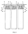
FIG 2 is a front view of a part of the preferred embodiment of the present invention; -
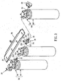
FIG 3 is an exploded view of a part of the preferred embodiment of the present invention; -
FIG 4 is a perspective view of the filter assembly of the preferred embodiment of the present invention; -
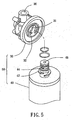
FIG 5 is a perspective view of a part of the preferred embodiment of the present invention, showing the top cover is disengaged with the housing; -
FIG 6 is a sectional view of a part of the preferred embodiment of the present invention, showing the top cover is engaged with the housing; -
FIG 7 is a perspective view of the preferred embodiment of the present invention, showing the housing is located at the second position. -
FIG 8 is a sectional view of a part of the preferred embodiment of the present invention, showing the top cover is disengaged with the housing. - As shown in
FIG 1 to FIG 6 , awater purification apparatus 90 in accordance with a preferred embodiment of the present invention comprises amain body 92, alid 96, fourholders 20, three top covers 30, and threehousings 40. - The
main body 92 has anaccommodation chamber 922 inside and aplate 94 on a top side thereof. - The
lid 96 is pivotally mounted on a front side of themain body 92 and closable on the front side of themain body 92 to close theaccommodation chamber 922 of themain body 92. - Referring to
FIG 2 andFIG 3 , theholders 20 each have a connectingportion 24, twodangling portions 21 on a top side of the connectingportion 24, and a pair of water-guidingportions 22 extending from two sides of the connectingportion 24. Thedangling portions 21 are fixed on theplate 94 of themain body 92 such that the top side of the connectingportion 24 of theholder 20 defines with a bottom side of theplate 94 of the main body 92 a distance. Theholders 20 further has a plurality of O-rings 221 fixed on the water-guidingportions 22. - Referring to
FIG 3 andFIG 5 , thetop cover 30 have acavity 31 on a bottom side thereof, aretaining portion 32, which is a spiral protrusion formed on a periphery of thecavity 31, aninlet 34 on a top section thereof, and anoutlet 36 on the opposite side of theinlet 34. One distal end of the water-guidingportion 22 of theholder 20 can be inserted into theinlet 34 or theoutlet 36 of thetop cover 30 and the O-rings 221 of theholder 20 fixed on the water-guidingportion 22 can be in contact with an inner periphery of theinlet 34 or theoutlet 36 of thetop cover 30 such that thetop cover 30 is pivotable about the axis of the water-guidingportions 22 of theholder 20 and water is stopped by the O-rings 221 of theholder 20. - The
housing 40 has a receiving chamber (not shown) inside for accommodation of a filter, ajamming portion 42, which is a spiral protrusion formed on a top side thereof, a firstwater filler hole 44 in communication with theinlet 34 of thetop cover 30 and asecond filler hole 46 in communication with theoutlet 36 of thetop cover 30. When the spiral protrusion of thehousing 40 is inserted in thecavity 31 of thetop cover 30 to attach to the spiral protrusion of thetop cover 30 and rotated 90 degrees, thehousing 40 and thetop cover 30 are engaged with each other to make up afilter assembly 50. Further, because of the existence of the distance between the connectingportion 24 of theholder 20 and theplate 94 of themain body 92 of thewater purification apparatus 90, thetop cover 30 and thehousing 40 can be pivotable relative to themain body 92 between a first position P1 where thehousing 40 is located in theaccommodation chamber 922 of themain body 92, as shown inFIG 1 , and a second position P2 where thehousing 40 is rotated to the outside of themain body 92, as shown inFIG 7 . - When a user wants to exchange the filter inside the
housing 40, he/she needs to pivot thefilter assembly 50 about the axis of the water-guidingportions 22 of theholder 20 so as to locate at the second position P2, as shown inFIG 7 , and then rotates thehousing 40 90 degrees clockwise such that thehousing 40 is separated from thetop cover 30, as shown inFIG 8 . Thus, the user can take the old filter out of thehousing 40 and place a new filter inside. Thereafter, the user can hold thehousing 40 to enable thejamming portion 42 to be inserted into thecavity 31 of thetop cover 30 and subsequently rotates thehousing 40 90 degrees counterclockwise such that thehousing 40 is engaged with thetop cover 30, asFIG 4 andFIG 6 , and pushes thefilter assembly 50 toward themain body 92 to locate at the first position PI, as shown inFIG 1 , thereby accomplishing the filter exchange work. - By means of the aforesaid design, the top cover and the housing has a simple coupling procedure for enabling the user to exchange the filter conveniently. Furthermore, because of the distance between the connecting portion of the holder and the plate of the main body, the filter assembly can be rotated to the outside of the main body of the water purification apparatus during the filter exchange work in spite of the restriction of the interior space of the main body.
- The invention being thus described, it will be obvious that the same may be varied in many ways.
Claims (4)
- A water purification apparatus (90) comprising:a main body (92) having an accommodation chamber (922) inside and a plate (94) on a top side thereof;a lid (96) pivotally mounted on the main body (92) and closable on the main body (92);a holder (20) mounted with the plate (94) of the main body (92) and defining a distance with the plate (94) of the main body (92);a top cover (30) pivotally mounted with the holder (20) and having a retaining portion (32), an inlet (34) and an outlet (36) opposite to the inlet (34); anda housing (40) having a jamming portion (42) detachably engageable with the retaining portion (32) of the top cover (30),wherein the retaining portion (32) of the top cover (30) is a spiral protrusion and the jamming portion (42) of the housing (40) is a spiral protrusion such that the housing (40) is engaged with the top cover (30) through the engagement of the spiral protrusion of the housing (40) and the spiral protrusion of the top cover (30), wherein said jamming portion exhibits a first water filler hole (44) in communication with the inlet (34) of the top cover (30) and a second water filler hole (46) in communication with the outlet (36) of the top cover (30).
- The water purification apparatus (90) as claimed in claim 1, wherein the distance is defined between a top side of a connecting portion (24) of the holder (20) and a bottom side of the plate (94) of the main body (92).
- The water purification apparatus (90) as claimed in claim 2, wherein the holder (20) further includes a pair of water-guiding portions (22) extending from two sides of the connecting portion (24) of the holder (20).
- The water purification apparatus (90) as claimed in claim 3, wherein the holder (20) further includes a plurality of O-rings (221), which are fixed on the water-guiding portions (22) and in contact with the inner periphery of the inlet (34) or the outlet (36) of the top cover (30) such that the top cover (30) is pivotable about the axis of the water-guiding portions (22) of the holder (20).
Applications Claiming Priority (1)
| Application Number | Priority Date | Filing Date | Title |
|---|---|---|---|
| CNU2006201315349U CN200954410Y (en) | 2006-08-21 | 2006-08-21 | Filter element positioning device for water purification system |
Publications (2)
| Publication Number | Publication Date |
|---|---|
| EP1892027A1 EP1892027A1 (en) | 2008-02-27 |
| EP1892027B1 true EP1892027B1 (en) | 2014-07-02 |
Family
ID=38624572
Family Applications (1)
| Application Number | Title | Priority Date | Filing Date |
|---|---|---|---|
| EP07015409.1A Active EP1892027B1 (en) | 2006-08-21 | 2007-08-06 | Water purification apparatus having a pivotable top cover |
Country Status (3)
| Country | Link |
|---|---|
| EP (1) | EP1892027B1 (en) |
| CN (1) | CN200954410Y (en) |
| ES (1) | ES2501440T3 (en) |
Families Citing this family (7)
| Publication number | Priority date | Publication date | Assignee | Title |
|---|---|---|---|---|
| GB201401351D0 (en) | 2014-01-27 | 2014-03-12 | Walker Filtration Ltd | Purification column |
| CN105036377B (en) * | 2015-08-05 | 2017-12-26 | 莱克电气绿能科技(苏州)有限公司 | Exempt from intelligent water purifier of the platform-type with self-watering of installation |
| CN105036442B (en) * | 2015-08-05 | 2017-08-04 | 莱克电气绿能科技(苏州)有限公司 | Platform-type intelligence water purifier |
| CN106984094A (en) * | 2017-05-10 | 2017-07-28 | 浙江光跃环保科技股份有限公司 | A kind of filter core fixed mechanism |
| CN109420379B (en) * | 2017-08-21 | 2021-03-19 | 蔡志豪 | Water purifying filter |
| PL235752B1 (en) * | 2018-04-26 | 2020-10-19 | Aquael Janusz Jankiewicz Spolka Z Ograniczona Odpowiedzialnoscia | Aquarium water filter |
| CN110847335A (en) * | 2019-12-03 | 2020-02-28 | 江苏盐西房地产开发有限公司 | Deodorization equipment convenient to disassemble, assemble and maintain for urban sewer |
Family Cites Families (5)
| Publication number | Priority date | Publication date | Assignee | Title |
|---|---|---|---|---|
| US6120685A (en) * | 1999-02-26 | 2000-09-19 | Maytag Corporation | Water filtering system with replaceable cartridge for a refrigerator |
| US20020104794A1 (en) * | 2001-02-06 | 2002-08-08 | Hoffmann Jack E. | Filter apparatus using alternate types of replaceable filter elements |
| TWI269665B (en) * | 2002-02-21 | 2007-01-01 | Roger P Reid | Quick change filter and bracket system with key system and universal key option |
| US6740235B2 (en) * | 2002-03-04 | 2004-05-25 | Culligan International Company | Swivelling filter head assembly |
| KR20040040938A (en) * | 2002-11-08 | 2004-05-13 | 에스케이 텔레콤주식회사 | The method of synchronizing the information of the client |
-
2006
- 2006-08-21 CN CNU2006201315349U patent/CN200954410Y/en not_active Expired - Lifetime
-
2007
- 2007-08-06 EP EP07015409.1A patent/EP1892027B1/en active Active
- 2007-08-06 ES ES07015409.1T patent/ES2501440T3/en active Active
Also Published As
| Publication number | Publication date |
|---|---|
| CN200954410Y (en) | 2007-10-03 |
| ES2501440T3 (en) | 2014-10-01 |
| EP1892027A1 (en) | 2008-02-27 |
Similar Documents
| Publication | Publication Date | Title |
|---|---|---|
| US7438811B2 (en) | Water purification apparatus | |
| US12311291B2 (en) | Water filtration system and method | |
| EP1892027A1 (en) | Water purification apparatus having a pivotable top cover | |
| US6926826B2 (en) | Quick change filter and bracket system with key system and universal key option | |
| EP3225293B1 (en) | Water purifying apparatus and refrigerator | |
| CN112408511A (en) | Filter | |
| TW200827010A (en) | Filter housing apparatus with rotating filter replacement mechanism | |
| CN217422277U (en) | Waterway switching assembly and faucet water purifier | |
| CN215842023U (en) | Filter element mounting structure for water purifier | |
| WO2013031378A1 (en) | Liquid treatment apparatus | |
| EP3434351B1 (en) | Head part for forming a liquid treatment apparatus and liquid treatment apparatus | |
| KR102689587B1 (en) | Filter connector assembly for water treatment | |
| CN217745987U (en) | Tap water purifier | |
| CN217139344U (en) | Filter element | |
| CN216045602U (en) | Faucet water purifier | |
| CN216878227U (en) | Water purifying device | |
| CN212687640U (en) | Pump assembly for water purifier, mounting seat assembly, supercharging device and water purifier | |
| CN212315599U (en) | Modular water purifier | |
| CN213668159U (en) | A faucet water purifier | |
| CN114259789A (en) | Water purifying device | |
| CN214634606U (en) | Water purifier, filtering mechanism, filter flask assembly and end cover unit | |
| CN104114256B (en) | Liquid filtration systems, assemblies and methods | |
| CN223221079U (en) | A water purifier | |
| JP5430058B2 (en) | Water purification cartridge and water purifier | |
| JP5500767B2 (en) | Water purifier |
Legal Events
| Date | Code | Title | Description |
|---|---|---|---|
| PUAI | Public reference made under article 153(3) epc to a published international application that has entered the european phase |
Free format text: ORIGINAL CODE: 0009012 |
|
| AK | Designated contracting states |
Kind code of ref document: A1 Designated state(s): AT BE BG CH CY CZ DE DK EE ES FI FR GB GR HU IE IS IT LI LT LU LV MC MT NL PL PT RO SE SI SK TR |
|
| AX | Request for extension of the european patent |
Extension state: AL BA HR MK YU |
|
| 17P | Request for examination filed |
Effective date: 20080827 |
|
| 17Q | First examination report despatched |
Effective date: 20081002 |
|
| AKX | Designation fees paid |
Designated state(s): AT BE BG CH CY CZ DE DK EE ES FI FR GB GR HU IE IS IT LI LT LU LV MC MT NL PL PT RO SE SI SK TR |
|
| GRAP | Despatch of communication of intention to grant a patent |
Free format text: ORIGINAL CODE: EPIDOSNIGR1 |
|
| INTG | Intention to grant announced |
Effective date: 20140129 |
|
| GRAS | Grant fee paid |
Free format text: ORIGINAL CODE: EPIDOSNIGR3 |
|
| GRAA | (expected) grant |
Free format text: ORIGINAL CODE: 0009210 |
|
| AK | Designated contracting states |
Kind code of ref document: B1 Designated state(s): AT BE BG CH CY CZ DE DK EE ES FI FR GB GR HU IE IS IT LI LT LU LV MC MT NL PL PT RO SE SI SK TR |
|
| REG | Reference to a national code |
Ref country code: GB Ref legal event code: FG4D |
|
| REG | Reference to a national code |
Ref country code: AT Ref legal event code: REF Ref document number: 675589 Country of ref document: AT Kind code of ref document: T Effective date: 20140715 Ref country code: CH Ref legal event code: EP |
|
| REG | Reference to a national code |
Ref country code: IE Ref legal event code: FG4D |
|
| REG | Reference to a national code |
Ref country code: CH Ref legal event code: NV Representative=s name: ROMAN VUILLE, CH |
|
| REG | Reference to a national code |
Ref country code: DE Ref legal event code: R096 Ref document number: 602007037427 Country of ref document: DE Effective date: 20140814 |
|
| REG | Reference to a national code |
Ref country code: ES Ref legal event code: FG2A Ref document number: 2501440 Country of ref document: ES Kind code of ref document: T3 Effective date: 20141001 |
|
| REG | Reference to a national code |
Ref country code: AT Ref legal event code: MK05 Ref document number: 675589 Country of ref document: AT Kind code of ref document: T Effective date: 20140702 |
|
| REG | Reference to a national code |
Ref country code: NL Ref legal event code: VDEP Effective date: 20140702 |
|
| REG | Reference to a national code |
Ref country code: LT Ref legal event code: MG4D |
|
| PG25 | Lapsed in a contracting state [announced via postgrant information from national office to epo] |
Ref country code: FI Free format text: LAPSE BECAUSE OF FAILURE TO SUBMIT A TRANSLATION OF THE DESCRIPTION OR TO PAY THE FEE WITHIN THE PRESCRIBED TIME-LIMIT Effective date: 20140702 Ref country code: BG Free format text: LAPSE BECAUSE OF FAILURE TO SUBMIT A TRANSLATION OF THE DESCRIPTION OR TO PAY THE FEE WITHIN THE PRESCRIBED TIME-LIMIT Effective date: 20141002 Ref country code: LT Free format text: LAPSE BECAUSE OF FAILURE TO SUBMIT A TRANSLATION OF THE DESCRIPTION OR TO PAY THE FEE WITHIN THE PRESCRIBED TIME-LIMIT Effective date: 20140702 Ref country code: PT Free format text: LAPSE BECAUSE OF FAILURE TO SUBMIT A TRANSLATION OF THE DESCRIPTION OR TO PAY THE FEE WITHIN THE PRESCRIBED TIME-LIMIT Effective date: 20141103 Ref country code: CZ Free format text: LAPSE BECAUSE OF FAILURE TO SUBMIT A TRANSLATION OF THE DESCRIPTION OR TO PAY THE FEE WITHIN THE PRESCRIBED TIME-LIMIT Effective date: 20140702 Ref country code: GR Free format text: LAPSE BECAUSE OF FAILURE TO SUBMIT A TRANSLATION OF THE DESCRIPTION OR TO PAY THE FEE WITHIN THE PRESCRIBED TIME-LIMIT Effective date: 20141003 Ref country code: SE Free format text: LAPSE BECAUSE OF FAILURE TO SUBMIT A TRANSLATION OF THE DESCRIPTION OR TO PAY THE FEE WITHIN THE PRESCRIBED TIME-LIMIT Effective date: 20140702 |
|
| PG25 | Lapsed in a contracting state [announced via postgrant information from national office to epo] |
Ref country code: NL Free format text: LAPSE BECAUSE OF FAILURE TO SUBMIT A TRANSLATION OF THE DESCRIPTION OR TO PAY THE FEE WITHIN THE PRESCRIBED TIME-LIMIT Effective date: 20140702 Ref country code: CY Free format text: LAPSE BECAUSE OF FAILURE TO SUBMIT A TRANSLATION OF THE DESCRIPTION OR TO PAY THE FEE WITHIN THE PRESCRIBED TIME-LIMIT Effective date: 20140702 Ref country code: LV Free format text: LAPSE BECAUSE OF FAILURE TO SUBMIT A TRANSLATION OF THE DESCRIPTION OR TO PAY THE FEE WITHIN THE PRESCRIBED TIME-LIMIT Effective date: 20140702 Ref country code: AT Free format text: LAPSE BECAUSE OF FAILURE TO SUBMIT A TRANSLATION OF THE DESCRIPTION OR TO PAY THE FEE WITHIN THE PRESCRIBED TIME-LIMIT Effective date: 20140702 Ref country code: IS Free format text: LAPSE BECAUSE OF FAILURE TO SUBMIT A TRANSLATION OF THE DESCRIPTION OR TO PAY THE FEE WITHIN THE PRESCRIBED TIME-LIMIT Effective date: 20141102 Ref country code: PL Free format text: LAPSE BECAUSE OF FAILURE TO SUBMIT A TRANSLATION OF THE DESCRIPTION OR TO PAY THE FEE WITHIN THE PRESCRIBED TIME-LIMIT Effective date: 20140702 |
|
| REG | Reference to a national code |
Ref country code: DE Ref legal event code: R097 Ref document number: 602007037427 Country of ref document: DE |
|
| PG25 | Lapsed in a contracting state [announced via postgrant information from national office to epo] |
Ref country code: SK Free format text: LAPSE BECAUSE OF FAILURE TO SUBMIT A TRANSLATION OF THE DESCRIPTION OR TO PAY THE FEE WITHIN THE PRESCRIBED TIME-LIMIT Effective date: 20140702 Ref country code: BE Free format text: LAPSE BECAUSE OF NON-PAYMENT OF DUE FEES Effective date: 20140831 Ref country code: EE Free format text: LAPSE BECAUSE OF FAILURE TO SUBMIT A TRANSLATION OF THE DESCRIPTION OR TO PAY THE FEE WITHIN THE PRESCRIBED TIME-LIMIT Effective date: 20140702 Ref country code: RO Free format text: LAPSE BECAUSE OF FAILURE TO SUBMIT A TRANSLATION OF THE DESCRIPTION OR TO PAY THE FEE WITHIN THE PRESCRIBED TIME-LIMIT Effective date: 20140702 Ref country code: DK Free format text: LAPSE BECAUSE OF FAILURE TO SUBMIT A TRANSLATION OF THE DESCRIPTION OR TO PAY THE FEE WITHIN THE PRESCRIBED TIME-LIMIT Effective date: 20140702 Ref country code: MC Free format text: LAPSE BECAUSE OF FAILURE TO SUBMIT A TRANSLATION OF THE DESCRIPTION OR TO PAY THE FEE WITHIN THE PRESCRIBED TIME-LIMIT Effective date: 20140702 |
|
| PLBE | No opposition filed within time limit |
Free format text: ORIGINAL CODE: 0009261 |
|
| STAA | Information on the status of an ep patent application or granted ep patent |
Free format text: STATUS: NO OPPOSITION FILED WITHIN TIME LIMIT |
|
| 26N | No opposition filed |
Effective date: 20150407 |
|
| PG25 | Lapsed in a contracting state [announced via postgrant information from national office to epo] |
Ref country code: SI Free format text: LAPSE BECAUSE OF FAILURE TO SUBMIT A TRANSLATION OF THE DESCRIPTION OR TO PAY THE FEE WITHIN THE PRESCRIBED TIME-LIMIT Effective date: 20140702 |
|
| PG25 | Lapsed in a contracting state [announced via postgrant information from national office to epo] |
Ref country code: MT Free format text: LAPSE BECAUSE OF FAILURE TO SUBMIT A TRANSLATION OF THE DESCRIPTION OR TO PAY THE FEE WITHIN THE PRESCRIBED TIME-LIMIT Effective date: 20140702 |
|
| PG25 | Lapsed in a contracting state [announced via postgrant information from national office to epo] |
Ref country code: LU Free format text: LAPSE BECAUSE OF NON-PAYMENT OF DUE FEES Effective date: 20140806 Ref country code: HU Free format text: LAPSE BECAUSE OF FAILURE TO SUBMIT A TRANSLATION OF THE DESCRIPTION OR TO PAY THE FEE WITHIN THE PRESCRIBED TIME-LIMIT; INVALID AB INITIO Effective date: 20070806 Ref country code: BE Free format text: LAPSE BECAUSE OF FAILURE TO SUBMIT A TRANSLATION OF THE DESCRIPTION OR TO PAY THE FEE WITHIN THE PRESCRIBED TIME-LIMIT Effective date: 20140702 |
|
| REG | Reference to a national code |
Ref country code: FR Ref legal event code: PLFP Year of fee payment: 10 |
|
| REG | Reference to a national code |
Ref country code: FR Ref legal event code: PLFP Year of fee payment: 11 |
|
| REG | Reference to a national code |
Ref country code: FR Ref legal event code: PLFP Year of fee payment: 12 |
|
| REG | Reference to a national code |
Ref country code: DE Ref legal event code: R082 Ref document number: 602007037427 Country of ref document: DE Representative=s name: STRAUS, ALEXANDER, DIPL.-CHEM.UNIV. DR.PHIL., DE Ref country code: DE Ref legal event code: R082 Ref document number: 602007037427 Country of ref document: DE Representative=s name: 2K PATENT- UND RECHTSANWAELTE PARTNERSCHAFT MB, DE |
|
| PGFP | Annual fee paid to national office [announced via postgrant information from national office to epo] |
Ref country code: IT Payment date: 20210831 Year of fee payment: 15 |
|
| PGFP | Annual fee paid to national office [announced via postgrant information from national office to epo] |
Ref country code: CH Payment date: 20210824 Year of fee payment: 15 Ref country code: TR Payment date: 20210730 Year of fee payment: 15 |
|
| REG | Reference to a national code |
Ref country code: CH Ref legal event code: PL |
|
| PG25 | Lapsed in a contracting state [announced via postgrant information from national office to epo] |
Ref country code: LI Free format text: LAPSE BECAUSE OF NON-PAYMENT OF DUE FEES Effective date: 20220831 Ref country code: CH Free format text: LAPSE BECAUSE OF NON-PAYMENT OF DUE FEES Effective date: 20220831 |
|
| PG25 | Lapsed in a contracting state [announced via postgrant information from national office to epo] |
Ref country code: IT Free format text: LAPSE BECAUSE OF NON-PAYMENT OF DUE FEES Effective date: 20220806 |
|
| REG | Reference to a national code |
Ref country code: DE Ref legal event code: R082 Ref document number: 602007037427 Country of ref document: DE Representative=s name: STRAUS, ALEXANDER, DIPL.-CHEM.UNIV. DR.PHIL., DE |
|
| PG25 | Lapsed in a contracting state [announced via postgrant information from national office to epo] |
Ref country code: TR Free format text: LAPSE BECAUSE OF NON-PAYMENT OF DUE FEES Effective date: 20220806 |
|
| PGFP | Annual fee paid to national office [announced via postgrant information from national office to epo] |
Ref country code: ES Payment date: 20250917 Year of fee payment: 19 |
|
| PGFP | Annual fee paid to national office [announced via postgrant information from national office to epo] |
Ref country code: DE Payment date: 20250831 Year of fee payment: 19 |
|
| PGFP | Annual fee paid to national office [announced via postgrant information from national office to epo] |
Ref country code: GB Payment date: 20250822 Year of fee payment: 19 |
|
| PGFP | Annual fee paid to national office [announced via postgrant information from national office to epo] |
Ref country code: FR Payment date: 20250827 Year of fee payment: 19 |
|
| PGFP | Annual fee paid to national office [announced via postgrant information from national office to epo] |
Ref country code: IE Payment date: 20250821 Year of fee payment: 19 |