EP1890374A2 - Method and apparatus for monitoring machinery vibration - Google Patents
Method and apparatus for monitoring machinery vibration Download PDFInfo
- Publication number
- EP1890374A2 EP1890374A2 EP07113410A EP07113410A EP1890374A2 EP 1890374 A2 EP1890374 A2 EP 1890374A2 EP 07113410 A EP07113410 A EP 07113410A EP 07113410 A EP07113410 A EP 07113410A EP 1890374 A2 EP1890374 A2 EP 1890374A2
- Authority
- EP
- European Patent Office
- Prior art keywords
- sensors
- stator core
- optical fiber
- stator
- controller
- Prior art date
- Legal status (The legal status is an assumption and is not a legal conclusion. Google has not performed a legal analysis and makes no representation as to the accuracy of the status listed.)
- Withdrawn
Links
- 238000000034 method Methods 0.000 title claims abstract description 19
- 238000012544 monitoring process Methods 0.000 title claims abstract description 13
- 239000013307 optical fiber Substances 0.000 claims abstract description 28
- 239000004020 conductor Substances 0.000 claims abstract description 15
- 230000002596 correlated effect Effects 0.000 claims description 4
- 230000008878 coupling Effects 0.000 abstract 1
- 238000010168 coupling process Methods 0.000 abstract 1
- 238000005859 coupling reaction Methods 0.000 abstract 1
- 238000004804 winding Methods 0.000 description 9
- 238000006073 displacement reaction Methods 0.000 description 4
- 239000000945 filler Substances 0.000 description 4
- 238000007689 inspection Methods 0.000 description 3
- 238000005259 measurement Methods 0.000 description 3
- 230000008439 repair process Effects 0.000 description 3
- 230000003292 diminished effect Effects 0.000 description 2
- 238000001914 filtration Methods 0.000 description 2
- 238000009413 insulation Methods 0.000 description 2
- 230000002035 prolonged effect Effects 0.000 description 2
- 230000001133 acceleration Effects 0.000 description 1
- 230000015556 catabolic process Effects 0.000 description 1
- 238000006731 degradation reaction Methods 0.000 description 1
- 239000000835 fiber Substances 0.000 description 1
- 238000012423 maintenance Methods 0.000 description 1
- 238000012986 modification Methods 0.000 description 1
- 230000004048 modification Effects 0.000 description 1
Images


Classifications
-
- H—ELECTRICITY
- H02—GENERATION; CONVERSION OR DISTRIBUTION OF ELECTRIC POWER
- H02K—DYNAMO-ELECTRIC MACHINES
- H02K11/00—Structural association of dynamo-electric machines with electric components or with devices for shielding, monitoring or protection
- H02K11/20—Structural association of dynamo-electric machines with electric components or with devices for shielding, monitoring or protection for measuring, monitoring, testing, protecting or switching
- H02K11/21—Devices for sensing speed or position, or actuated thereby
- H02K11/22—Optical devices
-
- H—ELECTRICITY
- H02—GENERATION; CONVERSION OR DISTRIBUTION OF ELECTRIC POWER
- H02K—DYNAMO-ELECTRIC MACHINES
- H02K11/00—Structural association of dynamo-electric machines with electric components or with devices for shielding, monitoring or protection
- H02K11/20—Structural association of dynamo-electric machines with electric components or with devices for shielding, monitoring or protection for measuring, monitoring, testing, protecting or switching
-
- H—ELECTRICITY
- H02—GENERATION; CONVERSION OR DISTRIBUTION OF ELECTRIC POWER
- H02K—DYNAMO-ELECTRIC MACHINES
- H02K3/00—Details of windings
- H02K3/46—Fastening of windings on the stator or rotor structure
- H02K3/48—Fastening of windings on the stator or rotor structure in slots
Definitions
- This invention is directed to a method and apparatus for continuous on-line monitoring of internal electrical machinery vibration and, in particular, can be used to monitor stator core and conductor vibration during normal operation of electrical machinery.
- stator bar can be damaged by, for example, loosening of the stator coil windings and insulation, fracturing or cracks occurring in the laminates, wedge shrinkage, and/or the ripple spring losing elasticity thereby causing the stator bars to move.
- generators are periodically scheduled for maintenance and inspection of the stator bar which involves taking the machines off-line and disassembling the machines for inspection and, if necessary, repair.
- the generators are periodically taken off-line without any evidence of damage or need for repair, resulting in unnecessary expense and operating inefficiencies for those instances when the inspections determine that there has not been any degradation of, or damage to, the stator bars.
- Various aspects of the present invention provide a system and method for continuously monitoring vibration data over the length of the stator bar while the machine is in operation. Sensors are placed in close proximity to each stator bar winding and the sensors are operatively coupled to a central controller that reads strain measurement data from each sensor and which correlates the strain measurement data from each sensor to the actual positions along the particular stator bar windings from which the data was obtained.
- the system comprises optical fibers wherein each optical fiber has spaced apart Bragg grating sensors disposed along its length.
- An optical fiber is installed along each wedge of the stator bar windings with the sensors being immune to the hostile environment of the stator core with its attendant large electric and magnetic fields.
- Alternative embodiments can employ sensors that measure other parameters such as, for example, temperature, displacement or acceleration.
- sensors that measure other parameters such as, for example, temperature, displacement or acceleration.
- piezoelectric sensors can be used to measure displacement caused by operating vibrations.
- an optical fiber sensor is disposed between a ripple spring and the inner most edge of the inner stator bar.
- the ripple spring is kept in place by wedges and is provided to maintain a tight fit between the wedges and the stator bar winding.
- Each optical fiber sensor comprises an interferometer and is operatively coupled to the central controller. The optical fiber sensors and controller operate such that a reflected signal from each sensor location along the optical fiber is modulated by a unique frequency so that band pass filtering allows the retrieval of each sensor's signal.
- the system monitors wedge tightness through direct measurement of strain on the ripple spring as determined by the optical fiber sensors and the reflected signals. More particularly, the optical fiber sensors provide data signals which can be correlated to the locations where the ripple spring has undergone a change in motion or displacement, i.e., strain. The locations at which the ripple spring has undergone changes indicate where loosening of the stator core windings and/or the other above described attendant problems can potentially occur.
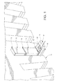
- FIGURE 1 shows the major components of a stator core winding to include stator core 10, inner stator bar 11, outer stator bar 12, slot liner 13 disposed between core 10 and outer stator bar 12, slot filler 14 disposed between outer stator bar 12 and inner stator bar 11, grooved slot filler 15 disposed between inner stator bar 11 and ripple spring 16, slide wedge 17 and end wedge 18. Also shown in FIGURE 1 is optical fiber sensor 19 disposed between ripple spring 16 and grooved slot filler 15.
- FIGURE 2 is an exploded view of the arrangement of grooved slot filler 15, optical fiber sensor 19, ripple spring 16, slide wedge 17 and end wedge 18.
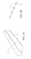
- Optical fiber sensor 19 is schematically shown in FIGURES 3A-3B to comprise a one fiber optic cable 30 with Bragg gratings sensors 32 distributed axially along the cable.
- FIGURE 3B shows cable 30 bonded to a coupon or ribbon 32 and
- FIGURE 3B shows the relative size of cable 30 and Bragg grating sensors 31.
- one or more cables 30 are operatively coupled to controller 33 which includes a tunable laser (not shown).
- Optical fiber sensor 19 and controller 33 can be obtained, for example, from Luna Innovations which provides a central controller under its marketing name "Distributed Sensing System.”
- central controller 33 transmits a signal along cable 30 and each Bragg grating sensor 31, located at axially displaced locations S1, S2 ... SN, forms an interferometer with the reference reflector R.
- the reflected signal from each Bragg grating sensor 31 is modulated by a unique frequency so that band pass filtering in central controller 33 allows for the retrieval of each sensor's signal.
- the reflected signals from each Bragg grating sensor 31 are indicative of the amount of strain on ripple spring 16 and by monitoring these signals over time a measure of the ripple spring's diminished elasticity can be obtained. More particularly, each of the reflected signals can be correlated to diminished elasticity of the ripple spring at the location of the Bragg grating sensor from which the reflected signal was received.
- the change in motion or displacement of ripple spring 16 is indicative of loosening of the stator coil windings and insulation, fracturing or cracks occurring in the laminates, and/or wedge shrinkage all of which can cause the stator bars to move.
Landscapes
- Engineering & Computer Science (AREA)
- Microelectronics & Electronic Packaging (AREA)
- Power Engineering (AREA)
- Measurement Of Mechanical Vibrations Or Ultrasonic Waves (AREA)
Abstract
An apparatus and method for monitoring vibration of the stator core and/or the conductors of electrical machinery during its operation involves positioning vibration sensors at the stator bar ends and operatively coupling the vibration sensors to a central controller. The vibration sensors are axially disposed along the length of an optical fiber and form an interferometer with a reference reflector. The central controller receives a reflected signal from each sensor which represents a measure of the vibration occurring in the stator core and/or the conductors at the location of the sensor.
Description
- This invention is directed to a method and apparatus for continuous on-line monitoring of internal electrical machinery vibration and, in particular, can be used to monitor stator core and conductor vibration during normal operation of electrical machinery.
- Over time, the normal operation of heavy electrical machinery - such as, for example, electrical generators, turbines or the like - can lead to damage of the stator core resulting in down time for repairs. More particularly, as normal operational vibrations occur during continued and prolonged operation of the machinery the stator bar can be damaged by, for example, loosening of the stator coil windings and insulation, fracturing or cracks occurring in the laminates, wedge shrinkage, and/or the ripple spring losing elasticity thereby causing the stator bars to move. Up until now, there has not been a way to reliably monitor stator core vibration while the machine is on line.
- To guard against prolonged and extensive vibration damage occurring to the stator bar, generators are periodically scheduled for maintenance and inspection of the stator bar which involves taking the machines off-line and disassembling the machines for inspection and, if necessary, repair. Thus, the generators are periodically taken off-line without any evidence of damage or need for repair, resulting in unnecessary expense and operating inefficiencies for those instances when the inspections determine that there has not been any degradation of, or damage to, the stator bars.
- Various aspects of the present invention provide a system and method for continuously monitoring vibration data over the length of the stator bar while the machine is in operation. Sensors are placed in close proximity to each stator bar winding and the sensors are operatively coupled to a central controller that reads strain measurement data from each sensor and which correlates the strain measurement data from each sensor to the actual positions along the particular stator bar windings from which the data was obtained.
- In an exemplary embodiment, the system comprises optical fibers wherein each optical fiber has spaced apart Bragg grating sensors disposed along its length. An optical fiber is installed along each wedge of the stator bar windings with the sensors being immune to the hostile environment of the stator core with its attendant large electric and magnetic fields.
- Alternative embodiments can employ sensors that measure other parameters such as, for example, temperature, displacement or acceleration. For example, piezoelectric sensors can be used to measure displacement caused by operating vibrations.
- In the exemplary embodiment, for each stator bar winding, an optical fiber sensor is disposed between a ripple spring and the inner most edge of the inner stator bar. The ripple spring is kept in place by wedges and is provided to maintain a tight fit between the wedges and the stator bar winding. Each optical fiber sensor comprises an interferometer and is operatively coupled to the central controller. The optical fiber sensors and controller operate such that a reflected signal from each sensor location along the optical fiber is modulated by a unique frequency so that band pass filtering allows the retrieval of each sensor's signal.
- The system monitors wedge tightness through direct measurement of strain on the ripple spring as determined by the optical fiber sensors and the reflected signals. More particularly, the optical fiber sensors provide data signals which can be correlated to the locations where the ripple spring has undergone a change in motion or displacement, i.e., strain. The locations at which the ripple spring has undergone changes indicate where loosening of the stator core windings and/or the other above described attendant problems can potentially occur.
- Various aspects and embodiments of the present invention will now be described in connection with the accompanying drawings, in which:
- FIGURE 1 shows the location of vibration sensors in an exemplary embodiment;
- FIGURE 2 shows an exploded view of the vibration sensors shown in FIGURE 1;
- FIGURES 3A-3B show more detail of the optical fiber that carries the vibration sensors; and
- FIGURE 4 shows in schematic block form an optical fiber with vibration sensors operatively coupled to a controller.
- FIGURE 1 shows the major components of a stator core winding to include
stator core 10,inner stator bar 11,outer stator bar 12,slot liner 13 disposed betweencore 10 andouter stator bar 12,slot filler 14 disposed betweenouter stator bar 12 andinner stator bar 11,grooved slot filler 15 disposed betweeninner stator bar 11 andripple spring 16,slide wedge 17 andend wedge 18. Also shown in FIGURE 1 isoptical fiber sensor 19 disposed betweenripple spring 16 and groovedslot filler 15. - FIGURE 2 is an exploded view of the arrangement of
grooved slot filler 15,optical fiber sensor 19,ripple spring 16,slide wedge 17 andend wedge 18. -
Optical fiber sensor 19 is schematically shown in FIGURES 3A-3B to comprise a one fiberoptic cable 30 with Bragggratings sensors 32 distributed axially along the cable.
FIGURE 3B showscable 30 bonded to a coupon orribbon 32 and FIGURE 3B shows the relative size ofcable 30 and Bragggrating sensors 31. - As schematically depicted in FIGURE 4, one or
more cables 30 are operatively coupled tocontroller 33 which includes a tunable laser (not shown).Optical fiber sensor 19 andcontroller 33 can be obtained, for example, from Luna Innovations which provides a central controller under its marketing name "Distributed Sensing System." In operation,central controller 33 transmits a signal alongcable 30 and each Bragggrating sensor 31, located at axially displaced locations S1, S2 ... SN, forms an interferometer with the reference reflector R. The reflected signal from each Bragggrating sensor 31 is modulated by a unique frequency so that band pass filtering incentral controller 33 allows for the retrieval of each sensor's signal. - The reflected signals from each Bragg
grating sensor 31 are indicative of the amount of strain onripple spring 16 and by monitoring these signals over time a measure of the ripple spring's diminished elasticity can be obtained. More particularly, each of the reflected signals can be correlated to diminished elasticity of the ripple spring at the location of the Bragg grating sensor from which the reflected signal was received. The change in motion or displacement ofripple spring 16 is indicative of loosening of the stator coil windings and insulation, fracturing or cracks occurring in the laminates, and/or wedge shrinkage all of which can cause the stator bars to move. - While the invention has been described in connection with what is presently considered to be the most practical and preferred embodiment, it is to be understood that the invention is not to be limited to the disclosed embodiment, but on the contrary, is intended to cover various modifications and equivalent arrangements included within the spirit and scope of the appended claims.
- Various aspects and embodiments of the present invention are defined in the following numbered clauses:
- 1. A system for monitoring stator core or conductor vibration during operation of electrical machinery, said system comprising:
- a plurality of sensors (31) disposed along at least one stator bar (11-12) of the stator core (10), said plurality of sensors (31) monitoring vibration of the at least one stator bar (11) during operation of the electrical machinery; and
- a controller (33) operatively coupled to said plurality of sensors (31) for receiving uniquely identified signals from each one of said plurality of sensors (31), and for converting said uniquely identified signals into stator core or conductor vibration data correlated to the location of each of said plurality of sensors (31).
- 2. A system as in
clause 1, wherein the plurality of sensors (31) are disposed along the length of at least one optical fiber (30). - 3. A system as in clause 2, wherein the at least one optical fiber (30) is disposed between a ripple spring (16) and a bottom edge of the at least one stator bar (11) of the stator core (10).
- 4. A system as in clause 3, wherein the plurality of sensors (31) disposed along the length of the at least one optical fiber (30) measure strain on the ripple spring (16).
- 5. A system as in any preceding clause, wherein the controller (33) transmits signals to said plurality of sensors (31) and the uniquely identified signals from each one of said plurality of sensors (31) are reflected back to said controller (33).
- 6. A system as in any preceding clause, wherein the controller (33) transmits signals to said plurality of sensors (31) and the uniquely identified signals from each one of said plurality of sensors (31) are reflected back to said controller.
- 7. A system as in any preceding clause, wherein the controller (33) transmits signals to said plurality of sensors (31) and the uniquely identified signals from each one of said plurality of sensors (31) are reflected back to said controller.
- 8. A system as in any preceding clause, wherein the controller (33) transmits signals to said plurality of sensors (31) and the uniquely identified signals from each one of said plurality of sensors (31) are reflected back to said controller.
- 9. A method of monitoring stator core or conductor vibration during operation of electrical machinery, said method comprising:
- locating a plurality of sensors (31) along at least one stator bar (10), (11) of the stator core (10), said plurality of sensors (31) monitoring vibration of the at least one stator bar (11) or associated conductors during operation of the electrical machinery; and
- receiving uniquely identified signals from each one of said plurality of sensors (31) at a central controller (33), and
- converting said uniquely identified signals into stator core or conductor vibration data at said central controller (33) which correlates said stator core or conductor vibration data to the location of each of said plurality of sensors (31).
- 10. A method as in clause 9, wherein the plurality of sensors (31) are disposed along the length of at least one optical fiber (30).
- 11. A method as in clause 9 or
clause 10, wherein the at least one optical fiber (30) is disposed between a ripple spring (16) and a bottom edge of the at least one stator bar (11) of the stator core (10). - 12. A method as in
clause 11, wherein the plurality of sensors (31) disposed along the length of the at least one optical fiber (30) sense strain on the ripple spring (16). - 13. A method as in any one of clauses 9 to 11, further including transmitting signals to said plurality of sensors (31) so that the uniquely identified signals from each one of said plurality of sensors are reflected back to said controller (33).
- 14. A method as in any one of
clauses 10 to 13, further including transmitting signals to said plurality of sensors (31) so that the uniquely identified signals from each one of said plurality of sensors are reflected back to said controller (33). - 15. A method as in any one of
clauses 10 to 14, further including transmitting signals to said plurality of sensors (31) so that the uniquely identified signals from each one of said plurality of sensors are reflected back to said controller (33). - 16. A method as in any one of
clauses 10 to 15, further including transmitting signals to said plurality of sensors (31) so that the uniquely identified signals from each one of said plurality of sensors are reflected back to said controller (33).
Claims (10)
- A system for monitoring stator core or conductor vibration during operation of electrical machinery, said system comprising:a plurality of sensors (31) disposed along at least one stator bar (11-12) of the stator core (10), said plurality of sensors (31) monitoring vibration of the at least one stator bar (11) during operation of the electrical machinery; anda controller (33) operatively coupled to said plurality of sensors (31) for receiving uniquely identified signals from each one of said plurality of sensors (31), and for converting said uniquely identified signals into stator core or conductor vibration data correlated to the location of each of said plurality of sensors (31).
- A system as in claim 1, wherein the plurality of sensors (31) are disposed along the length of at least one optical fiber (30).
- A system as in claim 2, wherein the at least one optical fiber (30) is disposed between a ripple spring (16) and a bottom edge of the at least one stator bar (11) of the stator core (10).
- A system as in claim 3, wherein the plurality of sensors (31) disposed along the length of the at least one optical fiber (30) measure strain on the ripple spring (16).
- A system as in any preceding claim, the controller (33) transmits signals to said plurality of sensors (31) and the uniquely identified signals from each one of said plurality of sensors (31) are reflected back to said controller (33).
- A method of monitoring stator core or conductor vibration during operation of electrical machinery, said method comprising:locating a plurality of sensors (31) along at least one stator bar (10), (11) of the stator core (10), said plurality of sensors (31) monitoring vibration of the at least one stator bar (11) or associated conductors during operation of the electrical machinery; andreceiving uniquely identified signals from each one of said plurality of sensors (31) at a central controller (33), andconverting said uniquely identified signals into stator core or conductor vibration data at said central controller (33) which correlates said stator core or conductor vibration data to the location of each of said plurality of sensors (31).
- A method as in claim 6, wherein the plurality of sensors (31) are disposed along the length of at least one optical fiber (30).
- A method as in claim 7, wherein the at least one optical fiber (30) is disposed between a ripple spring (16) and a bottom edge of the at least one stator bar (11) of the stator core (10).
- A method as in claim 8, wherein the plurality of sensors (31) disposed along the length of the at least one optical fiber (30) sense strain on the ripple spring (16).
- A method as in any one of claims 6 to 8, further including transmitting signals to said plurality of sensors (31) so that the uniquely identified signals from each one of said plurality of sensors are reflected back to said controller (33).
Applications Claiming Priority (1)
| Application Number | Priority Date | Filing Date | Title |
|---|---|---|---|
| US11/503,258 US20080036336A1 (en) | 2006-08-14 | 2006-08-14 | Method and apparatus for monitoring machinery vibration |
Publications (1)
| Publication Number | Publication Date |
|---|---|
| EP1890374A2 true EP1890374A2 (en) | 2008-02-20 |
Family
ID=38543927
Family Applications (1)
| Application Number | Title | Priority Date | Filing Date |
|---|---|---|---|
| EP07113410A Withdrawn EP1890374A2 (en) | 2006-08-14 | 2007-07-30 | Method and apparatus for monitoring machinery vibration |
Country Status (2)
| Country | Link |
|---|---|
| US (1) | US20080036336A1 (en) |
| EP (1) | EP1890374A2 (en) |
Cited By (6)
| Publication number | Priority date | Publication date | Assignee | Title |
|---|---|---|---|---|
| WO2010030456A3 (en) * | 2008-09-12 | 2010-12-29 | Siemens Energy, Inc. | Method and system for monitoring the condition of generator end windings |
| GB2473903A (en) * | 2009-07-21 | 2011-03-30 | Gen Electric | Stator end-winding component monitoring system |
| EP2363699A1 (en) * | 2010-03-02 | 2011-09-07 | Siemens Aktiengesellschaft | Vibration monitoring of a magnetic element in an electrical machine |
| GB2479263A (en) * | 2010-03-31 | 2011-10-05 | Gen Electric | Monitoring relative displacement of end-winding components in an electric generator |
| GB2483339A (en) * | 2010-08-30 | 2012-03-07 | Gen Electric | System and method for monitoring health of electrical machines |
| US8514409B2 (en) | 2010-03-31 | 2013-08-20 | General Electric Company | System for monitoring a relative displacement of components |
Families Citing this family (23)
| Publication number | Priority date | Publication date | Assignee | Title |
|---|---|---|---|---|
| US20090232183A1 (en) * | 2008-03-13 | 2009-09-17 | General Electric Company | System and method to measure temperature in an electric machine |
| US20090245717A1 (en) * | 2008-03-27 | 2009-10-01 | General Electric Company | System and method for measuring stator wedge tightness |
| US7852105B2 (en) * | 2008-12-05 | 2010-12-14 | General Electric Company | Winding diagnostic system and method |
| US8812254B2 (en) * | 2009-02-18 | 2014-08-19 | General Electric Company | Methods and systems for monitoring stator winding vibration |
| US8520986B2 (en) * | 2010-04-05 | 2013-08-27 | George Franklin Dailey | Use of fiber optic sensor techniques for monitoring and diagnostics of large AC generators |
| US8820167B2 (en) | 2011-02-10 | 2014-09-02 | Siemens Energy, Inc. | Vibration sensor |
| US8645101B2 (en) | 2011-02-10 | 2014-02-04 | Siemens Energy, Inc. | Method for monitoring the condition of a vibration sensor |
| US9120286B2 (en) | 2011-03-31 | 2015-09-01 | Fos Llc | Fiber optic sensor thermally matched support tubes for distributed fiber optic sensing |
| US8687175B2 (en) | 2011-05-05 | 2014-04-01 | Siemens Energy, Inc. | Fluid flow velocity and temperature measurement |
| US8736276B2 (en) | 2011-06-20 | 2014-05-27 | General Electric Company | Ripple spring and diagnostic method therefor |
| US8400042B2 (en) | 2011-06-20 | 2013-03-19 | General Electric Company | Ripple spring |
| US20130057104A1 (en) * | 2011-09-02 | 2013-03-07 | Steven Stretz | Permanent magnet motors and methods of assembling the same |
| US20130057107A1 (en) * | 2011-09-02 | 2013-03-07 | Steven Stretz | Permanent magnet motors and methods of assembling the same |
| US9477223B2 (en) | 2011-09-14 | 2016-10-25 | General Electric Company | Condition monitoring system and method |
| US8830448B2 (en) * | 2011-12-22 | 2014-09-09 | General Electric Company | Remote monitoring of tightness of stator windings |
| US10069367B2 (en) * | 2015-05-28 | 2018-09-04 | Mechanical Dynamics & Analysis Llc | Modified attachment system for springs in a generator rotor |
| EP3106890B1 (en) * | 2015-06-19 | 2025-08-13 | Arabelle Solutions France | Method for measuring a stator core of an electric machine and measuring device |
| US9973063B2 (en) * | 2015-10-09 | 2018-05-15 | General Electric Company | Combined stator wedge driver and bar jacking tool |
| CN105933182B (en) * | 2016-05-17 | 2019-07-05 | 哈尔滨电机厂有限责任公司 | Hydraulic generator rotor parameter monitoring system information transmits simulator stand |
| FR3064130B1 (en) * | 2017-03-15 | 2019-06-07 | Valeo Equipements Electriques Moteur | ROTOR OF ROTATING ELECTRIC MACHINE HAVING PERMANENT MAGNET HOLDING PIECES |
| US10340764B2 (en) * | 2017-03-30 | 2019-07-02 | Siemens Energy, Inc. | Retightenable wedge system for tightening coil in slot of generator stator |
| US10931179B2 (en) * | 2018-03-20 | 2021-02-23 | Aktiebolaget Skf | Fiber grounding brush |
| US11742723B2 (en) * | 2021-02-16 | 2023-08-29 | Siemens Energy, Inc. | Wedge tightness monitoring |
Family Cites Families (5)
| Publication number | Priority date | Publication date | Assignee | Title |
|---|---|---|---|---|
| US4612620A (en) * | 1983-06-06 | 1986-09-16 | Ird Mechanalysis, Inc. | Apparatus for collecting scheduled maintenance data |
| US6295510B1 (en) * | 1998-07-17 | 2001-09-25 | Reliance Electric Technologies, Llc | Modular machinery data collection and analysis system |
| DE19962668C1 (en) * | 1999-12-23 | 2000-12-07 | Siemens Ag | Optical measuring device for electrical apparatus such as generator or transformer |
| US6631335B2 (en) * | 2001-06-21 | 2003-10-07 | General Electric Co. | Method and apparatus for generator stator bar wedge pressure testing |
| US20040263342A1 (en) * | 2003-06-30 | 2004-12-30 | Matlock Milton Gregory | System for monitoring motors |
-
2006
- 2006-08-14 US US11/503,258 patent/US20080036336A1/en not_active Abandoned
-
2007
- 2007-07-30 EP EP07113410A patent/EP1890374A2/en not_active Withdrawn
Cited By (11)
| Publication number | Priority date | Publication date | Assignee | Title |
|---|---|---|---|---|
| WO2010030456A3 (en) * | 2008-09-12 | 2010-12-29 | Siemens Energy, Inc. | Method and system for monitoring the condition of generator end windings |
| US8076909B2 (en) | 2008-09-12 | 2011-12-13 | Siemens Energy, Inc. | Method and system for monitoring the condition of generator end windings |
| GB2473903A (en) * | 2009-07-21 | 2011-03-30 | Gen Electric | Stator end-winding component monitoring system |
| GB2473903B (en) * | 2009-07-21 | 2015-12-09 | Gen Electric | Stator end-winding component monitoring system |
| EP2363699A1 (en) * | 2010-03-02 | 2011-09-07 | Siemens Aktiengesellschaft | Vibration monitoring of a magnetic element in an electrical machine |
| GB2479263A (en) * | 2010-03-31 | 2011-10-05 | Gen Electric | Monitoring relative displacement of end-winding components in an electric generator |
| US8379225B2 (en) | 2010-03-31 | 2013-02-19 | General Electric Company | System for monitoring a relative displacement of components |
| US8514409B2 (en) | 2010-03-31 | 2013-08-20 | General Electric Company | System for monitoring a relative displacement of components |
| GB2479263B (en) * | 2010-03-31 | 2017-07-05 | Gen Electric | System for monitoring a relative displacement of components |
| GB2483339A (en) * | 2010-08-30 | 2012-03-07 | Gen Electric | System and method for monitoring health of electrical machines |
| US8310120B2 (en) | 2010-08-30 | 2012-11-13 | General Electric Company | System and method for monitoring health of electrical machines |
Also Published As
| Publication number | Publication date |
|---|---|
| US20080036336A1 (en) | 2008-02-14 |
Similar Documents
| Publication | Publication Date | Title |
|---|---|---|
| EP1890374A2 (en) | Method and apparatus for monitoring machinery vibration | |
| Thomson et al. | On-line current monitoring to diagnose airgap eccentricity in large three-phase induction motors-industrial case histories verify the predictions | |
| US8076909B2 (en) | Method and system for monitoring the condition of generator end windings | |
| EP1759168B1 (en) | Monitoring device for rotating body | |
| GB2458208A (en) | System and method to measure temperature in an electric machine | |
| US8275558B2 (en) | Visual inspection-based generator retention assembly tightness detection | |
| US6888124B1 (en) | Method to monitor internal parameters of electrical motor systems | |
| US6886977B2 (en) | Measuring temperature in stationary components of electrical machines using fiber optics | |
| EP2194388A2 (en) | Winding diagnostic system and method | |
| US8379225B2 (en) | System for monitoring a relative displacement of components | |
| JP5727728B2 (en) | Stator winding end component monitoring system | |
| JP2014524035A (en) | Fiber optic flux sensor for application to high voltage generator stator bars. | |
| EP2019302A1 (en) | Method and system for non-contact sensing of the torque of a shaft | |
| JP2000230935A (en) | Accelerometer and acceleration measuring device having the same | |
| US8514409B2 (en) | System for monitoring a relative displacement of components | |
| CN102405582A (en) | Electric machine comprising a rotor, a stator and an air gap between the rotor and the stator | |
| US10020764B2 (en) | System for compensating rotor vibrations | |
| US9151921B2 (en) | Apparatus for making uniform optical fiber bundles in power generators | |
| WO2015183297A1 (en) | Systems for monitoring power transformers and method of operating the same | |
| EP4372322B1 (en) | Electrical state monitoring related to a power cable | |
| EP3150983B1 (en) | System and method for monitoring machine condition and force measurement in a stator of an electrical machine | |
| Moore et al. | Generator stator end winding resonance: problems and solutions | |
| Hübner et al. | Monitoring of winding overhang vibrations on large synchronous motors | |
| Cloutier et al. | Case Studies of fiber optic accelerometer used for end-winding vibration monitoring on turbo-generators | |
| Mohammed | Investigation of Using Fibre Bragg Grating Sensing Technology for Thermal Condition Monitoring In Electric Machinery |
Legal Events
| Date | Code | Title | Description |
|---|---|---|---|
| PUAI | Public reference made under article 153(3) epc to a published international application that has entered the european phase |
Free format text: ORIGINAL CODE: 0009012 |
|
| AK | Designated contracting states |
Kind code of ref document: A2 Designated state(s): AT BE BG CH CY CZ DE DK EE ES FI FR GB GR HU IE IS IT LI LT LU LV MC MT NL PL PT RO SE SI SK TR |
|
| AX | Request for extension of the european patent |
Extension state: AL BA HR MK YU |
|
| STAA | Information on the status of an ep patent application or granted ep patent |
Free format text: STATUS: THE APPLICATION IS DEEMED TO BE WITHDRAWN |
|
| 18D | Application deemed to be withdrawn |
Effective date: 20110202 |