EP1890049A2 - Dual hydrostatic transmission - Google Patents
Dual hydrostatic transmission Download PDFInfo
- Publication number
- EP1890049A2 EP1890049A2 EP07113083A EP07113083A EP1890049A2 EP 1890049 A2 EP1890049 A2 EP 1890049A2 EP 07113083 A EP07113083 A EP 07113083A EP 07113083 A EP07113083 A EP 07113083A EP 1890049 A2 EP1890049 A2 EP 1890049A2
- Authority
- EP
- European Patent Office
- Prior art keywords
- neutral
- return
- control
- control arm
- rtn
- Prior art date
- Legal status (The legal status is an assumption and is not a legal conclusion. Google has not performed a legal analysis and makes no representation as to the accuracy of the status listed.)
- Granted
Links
- 230000002706 hydrostatic effect Effects 0.000 title claims abstract description 50
- 230000009977 dual effect Effects 0.000 title claims abstract description 26
- 230000005540 biological transmission Effects 0.000 title claims abstract description 23
- 230000007935 neutral effect Effects 0.000 claims abstract description 209
- 230000007246 mechanism Effects 0.000 claims abstract description 43
- 230000033001 locomotion Effects 0.000 claims abstract description 8
- 230000004044 response Effects 0.000 claims abstract description 6
- 230000008859 change Effects 0.000 claims description 3
- 244000025254 Cannabis sativa Species 0.000 description 7
- 239000012530 fluid Substances 0.000 description 3
- 238000002485 combustion reaction Methods 0.000 description 1
- 230000004048 modification Effects 0.000 description 1
- 238000012986 modification Methods 0.000 description 1
- 238000000926 separation method Methods 0.000 description 1
Images




Classifications
-
- F—MECHANICAL ENGINEERING; LIGHTING; HEATING; WEAPONS; BLASTING
- F16—ENGINEERING ELEMENTS AND UNITS; GENERAL MEASURES FOR PRODUCING AND MAINTAINING EFFECTIVE FUNCTIONING OF MACHINES OR INSTALLATIONS; THERMAL INSULATION IN GENERAL
- F16D—COUPLINGS FOR TRANSMITTING ROTATION; CLUTCHES; BRAKES
- F16D31/00—Fluid couplings or clutches with pumping sets of the volumetric type, i.e. in the case of liquid passing a predetermined volume per revolution
- F16D31/02—Fluid couplings or clutches with pumping sets of the volumetric type, i.e. in the case of liquid passing a predetermined volume per revolution using pumps with pistons or plungers working in cylinders
-
- F—MECHANICAL ENGINEERING; LIGHTING; HEATING; WEAPONS; BLASTING
- F16—ENGINEERING ELEMENTS AND UNITS; GENERAL MEASURES FOR PRODUCING AND MAINTAINING EFFECTIVE FUNCTIONING OF MACHINES OR INSTALLATIONS; THERMAL INSULATION IN GENERAL
- F16H—GEARING
- F16H61/00—Control functions within control units of change-speed- or reversing-gearings for conveying rotary motion ; Control of exclusively fluid gearing, friction gearing, gearings with endless flexible members or other particular types of gearing
- F16H61/38—Control of exclusively fluid gearing
- F16H61/40—Control of exclusively fluid gearing hydrostatic
- F16H61/42—Control of exclusively fluid gearing hydrostatic involving adjustment of a pump or motor with adjustable output or capacity
- F16H61/437—Pump capacity control by mechanical control means, e.g. by levers or pedals
-
- F—MECHANICAL ENGINEERING; LIGHTING; HEATING; WEAPONS; BLASTING
- F16—ENGINEERING ELEMENTS AND UNITS; GENERAL MEASURES FOR PRODUCING AND MAINTAINING EFFECTIVE FUNCTIONING OF MACHINES OR INSTALLATIONS; THERMAL INSULATION IN GENERAL
- F16H—GEARING
- F16H61/00—Control functions within control units of change-speed- or reversing-gearings for conveying rotary motion ; Control of exclusively fluid gearing, friction gearing, gearings with endless flexible members or other particular types of gearing
- F16H61/38—Control of exclusively fluid gearing
- F16H61/40—Control of exclusively fluid gearing hydrostatic
- F16H61/42—Control of exclusively fluid gearing hydrostatic involving adjustment of a pump or motor with adjustable output or capacity
- F16H61/439—Control of the neutral position, e.g. by zero tilt rotation holding means
Definitions
- This invention relates generally to hydrostatic drives for grass mowing machines, and more return to neutral mechanisms for dual hydrostatic transmissions.
- a grass mowing machine may include a motor or engine that transmits power to left and right traction drive wheels through a dual hydrostatic transmission.
- the operator may use a pair of controls connected to the dual hydrostatic transmission to control machine speed and direction.
- Examples of grass mowing machines with dual hydrostatic transmissions to control speed and direction are zero turning radius mowers, walk-behind mowers, stand-behind mowers and other riding mowers.
- a dual hydrostatic transmission may include two hydrostatic pumps in one housing, each pump having an input control or trunnion shaft.
- Each input control or trunnion shaft may be operatively connected to a swash plate in one of the pumps.
- Each pump may be connected to a hydrostatic motor that turns a drive wheel.
- Each input control or trunnion shaft may be pivoted in a first rotary direction to move the swash plate in the pump for propelling a traction drive wheel on the vehicle forward, and may be pivoted in an opposite rotary direction to move the swash plate and propel the traction drive wheel in the reverse direction.
- Each input control or trunnion shaft and swash plate may have a forward drive pivot direction, an opposite reverse drive pivot direction, and a neutral position between the forward drive and reverse drive pivot directions.
- a dual hydrostatic transmission may include operator controls and linkages connected to each input control or trunnion shaft to allow an operator to independently change the direction and speed of each drive wheel.
- each operator control may be a pivotable stick or foot pedal, and the operator may use the pair of sticks or foot pedals to control speed and direction of the machine.
- each linkage may include a return to neutral mechanism that urges the input control or trunnion shaft and swash plate toward the neutral position when the operator releases the stick or foot pedal.
- each operator control also may have a damper to help control motion.
- Return to neutral mechanisms may be connected to electrical circuits that prevent the engine or other power source from being started if the transmission is in a driving, non-neutral mode, and thereby generally prevent the vehicle from lunging forward when started. Examples of return to neutral mechanisms are shown in US Patent Nos. 6,935,106 , 5,586,955 and 4,531,365 .
- a dual hydrostatic transmission between an engine and a pair of traction drive wheels may have first and second hydraulic pumps, each pump having a trunnion shaft connected to an independently movable operator control. It may be provided a return to neutral mechanism comprising a plurality of return to neutral control arms, each return to neutral control arm connected to another return to neutral control arm by a spring biasing both arms toward a neutral position; each return to neutral control arm moving in response to movement of an operator control; and a plurality of switches mounted to the return to neutral control arms, the switches enabling starting of the engine if every return to neutral control arm is in a neutral position, the switches disabling starting of the engine if at least one return to neutral control arm is out of the neutral position.
- a return to neutral mechanism for a dual hydrostatic transmission may include return to neutral control arms, each return to neutral control arm biased toward a neutral position. Each return to neutral control arm may move in response to movement of an operator control, such as a stick or foot pedal. Switches may be mounted to the return to neutral control arms. The switches may enable starting of the engine if every return to neutral control arm is in a neutral position, and disable starting of the engine if at least one return to neutral control arm is out of the neutral position.
- Such return to neutral mechanism has a low number of components, and is easy and economical to assemble, service and adjust.
- An return to neutral mechanism for a dual hydrostatic transmission having first and second hydrostatic pumps with first and second trunnion shafts may have a first pair of return to neutral control arms mounted on an axis that is coaxial with and independent of the first trunnion shaft, one of the first pair of return to neutral control arms pivoting in a first direction if the first hydrostatic pump is in forward, and the other of the first pair of return to neutral control arms pivoting in a second direction if the first hydrostatic pump is in reverse; a second pair of return to neutral control arms pivoting on an axis that is coaxial with and independent of the second trunnion shaft, one of the second pair of return to neutral control arms pivoting in a first direction if the second hydrostatic pump is in forward, and the other of the second pair of return to neutral control arms pivoting in a second direction if the second hydrostatic pump is in reverse; springs biasing the return to neutral control arms toward a neutral position; and first and second switches mounted to one of the first pair of return to neutral
- the springs may extend between one of the first pair of return to neutral control arms and one of the second pair of return to neutral control arms.
- the return to neutral mechanism may further comprise a neutral locating plate mounted to the dual hydrostatic transmission and having a pair of tabs toward which the return to neutral control arms are biased in their neutral positions.
- the switches may be plunger type switches.
- the return to neutral mechanism may further comprise a hub mounted to each trunnion shaft, each hub providing a rotational axis around which each return to neutral control arm rotates independently of the hub.
- a return to neutral mechanism for a dual hydrostatic transmission between an engine and a pair of traction drive wheels in another embodiment may comprise first and second operator controls connected to first and second trunnion shafts for first and second hydrostatic pumps; a first pair of return to neutral control arms for the first pump, and a second pair of return to neutral control arms for the second pump, each return to neutral control arm independently pivoting around a hub on the trunnion shaft and biased toward a neutral position; and a first switch having a first state only if both of the first pair of return to neutral control arms are in the neutral position, and a second switch having a first state only if both of the second pair of return to neutral control arms are in the neutral position, the engine enabled to start only if both switches are in the first state.
- the first switch may be mounted to one of the first pair of return to neutral control arms and the second switch is mounted to one of the second pair of return to neutral control arms.
- the first and second operator controls may be pivotable sticks.
- the first and second return to neutral control arms may pivot on axes that are coaxial with the trunnion shafts.
- the return to neutral mechanism may further comprise at least one spring between the first pair of return to neutral control arms and the second pair of return to neutral control arms, the spring urging the return to neutral control arms toward a neutral position.
- the hubs may further comprise mounting flanges.
- the return to neutral mechanism may further comprise input control levers mounted to the flanges, and the operator controls are pivotably connected to the input control levers.
- the flanges may have oval holes permitting adjusting the axial position of each input control levers in relation to the axial position of the flange.
- One of the return to neutral control arms in a pair pivots if the corresponding operator control and hydrostatic pump may move to a forward position, and the other of the return to neutral control arms in a pair pivots in the opposite direction if the corresponding operator control and hydrostatic pump moves to a reverse position.
- the return to neutral mechanism may further comprising a neutral locating plate mounted to the hydrostatic transmission and providing stops for the return to neutral control arms.
- the return to neutral mechanism may further comprise a tab extending from each return to neutral control arm contacting one of the stops on the neutral locating plate defining the neutral position.
- Each return to neutral control arm may include a shoulder that contacts one of the stops of the neutral locating plate if the arm reaches a maximum position.
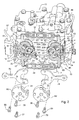
- Figs. 1-3 show one embodiment of return to neutral mechanism 10 mounted to dual hydrostatic pump 11 housing a pair of hydrostatic pumps 12, 13.
- return to neutral mechanism 10 may be mounted to a pair of hydrostatic pumps that are side-by-side.
- Each hydrostatic pump 12, 13 may be connected by a fluid conduit to a hydrostatic motor that rotates a traction drive wheel on a grass mowing machine, preferably a left wheel and a right wheel.
- the amount and direction of flow of hydraulic fluid between each pump 12, 13 and its motor is controlled by operator controls 76, 78.
- the operator controls may be independently movable controls such as a pair of sticks or foot pedals, one for each pump. Pushing both operator controls in a forward direction may cause both traction drive wheels to rotate forward.
- operator controls 76, 78 may be pivotable sticks that an operator may use to control speed and direction of a left traction drive wheel and a right traction drive wheel respectively.
- Operator controls 76, 78 may be pivotably connected to input control levers 72, 74.
- the left and right input control levers 72, 74 may be attached to trunnion shafts 14, 15.
- Left hydrostatic pump 12 may have left input control or trunnion shaft 14 and right pump 13 may have right input control or trunnion shaft 15.
- Turning an input control lever may pivot an internal swash plate (not shown) inside the hydrostatic pump to direct hydraulic fluid flow and thus change the rotational speed of the hydrostatic motor that turns a drive wheel.
- the dual hydrostatic pump also may have a vertical input shaft 17 that may be rotated by an internal combustion engine or other power supply source (not shown), through a belt and pulley arrangement.
- return to neutral mechanism 10 may include upper return to neutral control arms 41, 42 and lower return to neutral control arms 51, 52. Each return to neutral control arm may be connected to another return to neutral control arm by a spring 37, 39 biasing both arms toward a neutral position. Each return to neutral control arm moves in response to movement of an operator control 76, 78, such as a stick or foot pedal. Additionally, the return to neutral mechanism may include switches 61, 62 mounted to the return to neutral control arms. The switches enable starting of the engine if every return to neutral control arm is in a neutral position, and disable starting of the engine if at least one return to neutral control arm is out of the neutral position.
- return to neutral mechanism 10 may urge each pump 12, 13 to return to its hydraulic neutral position from either a forward or reverse position, as well as simultaneously sense whether or not the pumps are in their neutral position.
- a first pair of return to neutral control arms 41, 51 pivots around hub 34 on an axis that is coaxial with and independent of trunnion shaft 14.
- One of the first pair of return to neutral control arms pivots in a first direction if hydrostatic pump 12 is in forward, and the other of the first pair of return to neutral control arms pivots in a second direction if hydrostatic pump 12 is in reverse.
- a second pair of return to neutral control arms 42, 52 pivots around hub 35 on an axis that is coaxial with and independent of trunnion shaft 15.
- One of the second pair of return to neutral control arms pivots in a first direction if hydrostatic pump 13 is in forward, and the other of the second pair of return to neutral control arms pivots in a second direction if hydrostatic pump 13 is in reverse.
- Springs 37, 39 bias the return to neutral control arms toward a mechanical neutral position.
- Switches 61, 62 are mounted to one of the first pair of return to neutral control arms and one of the second pair of return to neutral control arms. Each switch is in a first state to enable starting of the engine only if all of the return to neutral control arms are in a mechanical neutral position.
- return to neutral mechanism 10 may include neutral locating plate 16 mounted to dual hydrostatic pump 11 using internal hex screws 21-24.
- the neutral locating plate may have a pair of tabs 18, 19, preferably a left tab extending from its left edge and a right tab extending from its right edge.
- Each tab 18, 19 may serve as a mechanical neutral locating stop for the return to neutral (RTN) control levers, as will be explained below.
- the neutral locating plate also may have a pair of openings through which left and right input control or trunnion shafts 14, 15 may extend.
- pump trunnion hubs 34, 35 may be mounted to left and right input control or trunnion shafts 14, 15 and may drive the shafts using the operator controls.
- the pump trunnion hubs may be mounted to the shafts with tapered internal hex set screws 90, 91. Each set screw may index into a tapered alignment hole in the shaft and secure the hub to the shaft. The set screws may be accessible for securing prior to mounting input control levers 72, 74 to flanges 80, 82 of hubs 34,35.
- input control levers 72, 74 may be secured to flanges 80, 82 with internal hex screws 65-67 and 68-70.
- the hex screws may thread into input control levers 72, 74.
- Oval slots in flanges 80, 82 allow for indexing the pump's hydraulic neutral to the mechanical fixed neutral which the upper and lower RTN control arms reach when they contact tabs 18, 19 of the neutral locating plate.
- the hex screws may secure the input control levers at various axial positions within the oval slots.
- the axial position of each input control lever 72, 74 may be varied relative to the axial position of each flange 80, 82.
- each input control lever 72, 74 and operator control 76, 78 can be adjusted to match the hydraulic neutral position of each hydrostatic pump 12, 13.
- Springs 37, 39 urge the upper and lower RTN control arms toward tabs 18, 19 which provide a stop defining the mechanical neutral position.
- pump trunnion hubs 34, 35 may serve as centering pivot locations for frictionless washers 32A, 32B, 32C and 33A, 33B, 33C.
- the frictionless washers may be positioned between the return to neutral (RTN) control arms on the same pump trunnion hub to allow the arms to freely pivot around the hub.
- RTN return to neutral
- the frictionless washers allow pivoting of the RTN control arms without undue resistance, and also maintain axial separation between the RTN control arms and provide proper alignment of components on the hubs.
- left upper RTN control arm 41 and right upper RTN control arm 42 pivot independently around pump trunnion hubs 34, 35 respectively.
- the left upper RTN control arm and right upper RTN control arm each have a tab 44, 45 extending therefrom that contacts a respective tab 18, 19 of neutral locating plate 16 in the mechanical neutral position.
- Each upper RTN control arm 41, 42 includes an opening that fits around pump trunnion hub 34, 35 to allow the upper RTN control arm to pivot.
- Spring 37 may be hooked in slots of legs 47, 48 extending from upper RTN control arms 41, 42. Spring 37 biases both upper RTN control arms together and toward their neutral positions, until tabs 44, 45 meet tabs 18, 19 respectively.
- each lower RTN control arm 51, 52 pivots in the opposite direction as each upper RTN control arm 41, 42 around the same hub.
- Left lower RTN control arm 51 and right lower RTN control arm 52 each have a tab 54, 55 extending therefrom that can contact a respective tab 18, 19 of neutral locating plate 16.
- Each lower RTN control arm 51, 52 includes an opening that fits around pump trunnion hub 34, 35 to allow the lower RTN control arm to pivot.
- Spring 39 may be hooked in slots of legs 57, 58 extending from lower RTN control arms 51, 52. Spring 39 biases both lower RTN control arms together and toward their neutral positions, until tabs 54, 55 meet tabs 18, 19 respectively.
- electrical plunger switches 61, 62 may be mounted to slots in tabs 54, 55 of lower RTN control arms 51, 52.
- the electrical plunger switches may be provided with various switching logics to enable starting of a grass mowing machine only when all of the RTN control arms are at a neutral position.
- the switches may enable other functions only if the operator controls are in the neutral position, such as disabling the engine if the park brake is set and the operator controls are moved out of the neutral position.
- Switches 61, 62 may be activated by pivoting either of the lower RTN control arms, separating the switch and a tab on the RTN control arm.
- the switches may be electronically connected via electrical conduits 97, 98 to a controller, circuit or other device (not shown) that can enable or disable the engine of a grass mowing machine.
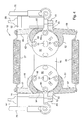
- Fig. 4 shows an embodiment of return to neutral mechanism 10 in which operator controls 76, 77 and control levers 72, 74 for both pumps are in a neutral position.
- Springs 37, 39 bias the upper and lower RTN control arms 41, 42 and 51, 52 to pivot to a position in which tabs 44, 45 and tabs 54, 55 are in contact with tabs 18, 19 on each side of neutral locating plate 16.
- both plunger type switches 61, 62 may be in a first state, shown here as a compressed condition.
- the switches may complete a circuit required for engine starting and/or other machine functions that are enabled only in neutral.
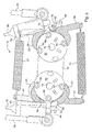
- Fig. 5 shows an embodiment of return to neutral mechanism 10 in which left operator control 76 and control lever 72 for the left pump are in neutral, and right operator control 78 and control lever 74 for the right pump are in the full forward position.
- Right input control lever 74 causes right lower RTN control arm 52 to pivot by contacting tab 55. Pivoting of right lower RTN control arm 52 also changes the state of plunger switch 62, here shown in a released or extended condition. This switch state may open a circuit to disable engine starting and/or other functions of the grass mowing machine. Pivoting of right lower RTN control arm 52 also stretches and extends spring 39 between legs 57 and 58 of lower RTN control arms 51, 52.
- Right lower RTN control arm 52 may reach a maximum or full forward position when shoulder 93 contacts tab 19 of neutral locating plate 16.
- Fig. 6 shows an embodiment of return to neutral mechanism 10 in which right operator control 78 and control lever 74 for the right pump are in neutral, and left operator control 76 and control lever 72 are in the full forward position.
- Left input control lever 72 causes left lower RTN control arm 51 to pivot by contacting tab 54. Pivoting of left lower RTN control arm 51 also changes the state of plunger switch 61, here shown in a released or extended condition. Pivoting of left lower RTN control arm 51 also stretches and extends spring 39 between legs 57 and 58 of the lower RTN control arms. Left lower RTN control arm 51 may reach a maximum or full forward position when shoulder 92 contacts tab 18 of neutral locating plate 16.
- Right lower RTN control arm 52, and both upper RTN control arms 41, 42 remain in their mechanical neutral positions. Tab 45 of right lower RTN control arm 52, and tabs 54, 55 of upper RTN control arms 41, 42, remain in contact with tabs 18, 19 of neutral locating plate 16.
- Fig. 7 shows an embodiment of return to neutral mechanism 10 in which right operator control 78 and control lever 74 for the right pump are in neutral, and left operator control 76 and control lever 72 are in the full reverse position.
- Left input control lever 72 causes left upper RTN control arm 41 to pivot by contacting tab 44. Pivoting of left upper RTN control arm 41 also changes the state of plunger switch 61, here shown in a released or extended condition. Pivoting of left upper RTN control arm 41 also stretches and extends spring 37 between legs 47 and 48 of the upper RTN control arms. Left upper RTN control arm 41 may reach a maximum or full reverse position when shoulder 94 contacts tab 18 of the neutral locating plate.
- Right upper RTN control arm 42, and both lower RTN control arms 51, 52 remain in their mechanical neutral positions. Tab 45 of right upper RTN control arm 42, and tabs 54, 55 of lower RTN control arms 51, 52, remain in contact with tabs 18, 19 of neutral locating plate 16.
- Fig. 8 shows an embodiment of return to neutral mechanism 10 in which left operator control 76 and control lever 72 for the left pump are in neutral, and right operator control 78 and control lever 74 are in the full reverse position.
- Right input control lever 74 causes right upper RTN control arm 42 to pivot by contacting tab 45. Pivoting of right upper RTN control arm 42 also changes the state of plunger switch 62, here shown in a released or extended condition. Pivoting of right upper RTN control arm 42 also stretches and extends spring 37 between legs 47 and 48 of the upper RTN control arms.
- Right upper RTN control arm 42 may reach a maximum or full reverse position when shoulder 95 contacts tab 19 of the neutral locating plate.
- Left upper RTN control arm 41, and both lower RTN control arms 51, 52 remain in their mechanical neutral positions. Tab 44 of left upper RTN control arm 41, and tabs 54, 55 of lower RTN control arms 51, 52, remain in contact with tabs 18, 19 of the neutral locating plate.
- Fig. 9 shows an embodiment of return to neutral mechanism 10 in which both operator controls 76, 78 and control levers 72, 74 for the left and right pumps are in the full forward position.
- Left input control lever 72 causes left lower RTN control arm 51 to pivot by contacting tab 54.
- Right input control lever 74 causes right lower RTN control arm 52 to pivot by contacting tab 55.
- Pivoting of left lower RTN control arm 51 changes the state of plunger switch 61, here shown in a released or extended condition.
- Pivoting of right lower RTN control arm 52 changes the state of plunger switch 62, here shown in a released or extended cond ition.
- Pivoting of left and right lower RTN control arms 51, 52 also stretches and extends spring 39 between legs 57 and 58 of the lower RTN control arms.
- Left lower RTN control arm may reach a maximum or full forward position when shoulder 92 contacts tab 18 of the neutral locating plate.
- Right lower RTN control arm 52 may reach a maximum or full forward position when shoulder 93 contacts tab 19 of the neutral locating plate.
- Both upper RTN control arms 41, 42 remain in their mechanical neutral positions.
- Tab 44 of left upper RTN control arm 41, and tab 45 of right upper RTN control arm 42, remain in contact with tabs 18, 19 of the neutral locating plate.
Landscapes
- Engineering & Computer Science (AREA)
- General Engineering & Computer Science (AREA)
- Mechanical Engineering (AREA)
- Control Of Fluid Gearings (AREA)
- Arrangement Or Mounting Of Control Devices For Change-Speed Gearing (AREA)
- Gear-Shifting Mechanisms (AREA)
- Control Of Transmission Device (AREA)
Abstract
Description
- This invention relates generally to hydrostatic drives for grass mowing machines, and more return to neutral mechanisms for dual hydrostatic transmissions.
- A grass mowing machine may include a motor or engine that transmits power to left and right traction drive wheels through a dual hydrostatic transmission. The operator may use a pair of controls connected to the dual hydrostatic transmission to control machine speed and direction. Examples of grass mowing machines with dual hydrostatic transmissions to control speed and direction are zero turning radius mowers, walk-behind mowers, stand-behind mowers and other riding mowers.
- A dual hydrostatic transmission may include two hydrostatic pumps in one housing, each pump having an input control or trunnion shaft. Each input control or trunnion shaft may be operatively connected to a swash plate in one of the pumps. Each pump may be connected to a hydrostatic motor that turns a drive wheel. Each input control or trunnion shaft may be pivoted in a first rotary direction to move the swash plate in the pump for propelling a traction drive wheel on the vehicle forward, and may be pivoted in an opposite rotary direction to move the swash plate and propel the traction drive wheel in the reverse direction. Each input control or trunnion shaft and swash plate may have a forward drive pivot direction, an opposite reverse drive pivot direction, and a neutral position between the forward drive and reverse drive pivot directions.
- A dual hydrostatic transmission may include operator controls and linkages connected to each input control or trunnion shaft to allow an operator to independently change the direction and speed of each drive wheel. For example, each operator control may be a pivotable stick or foot pedal, and the operator may use the pair of sticks or foot pedals to control speed and direction of the machine. Additionally, each linkage may include a return to neutral mechanism that urges the input control or trunnion shaft and swash plate toward the neutral position when the operator releases the stick or foot pedal. Optionally, each operator control also may have a damper to help control motion.
- Return to neutral mechanisms may be connected to electrical circuits that prevent the engine or other power source from being started if the transmission is in a driving, non-neutral mode, and thereby generally prevent the vehicle from lunging forward when started. Examples of return to neutral mechanisms are shown in
US Patent Nos. 6,935,106 ,5,586,955 and4,531,365 . - Return to neutral mechanisms for dual hydrostatic transmissions require numerous mechanical linkages and other components. The device must return the pump to mechanical neutral from both the forward and reverse motion positions. A return to neutral mechanism for a dual hydrostatic pump is needed having a low number of components.
- Mechanical linkages and other components for a dual hydrostatic pump's return to neutral mechanism are costly to assemble, service and adjust in the field. A return to neutral mechanism for a dual hydrostatic pump is needed that is economical to assemble, service and adjust.
- It is therefore an object of the present invention to provide a dual hydrostatic transmission comprising a neutral mechanism meeting this need.
- This object is met according to the invention by the teaching of claim 1, while features developing the solution in an advantageous way are set forth in the further claims.
- A dual hydrostatic transmission between an engine and a pair of traction drive wheels, may have first and second hydraulic pumps, each pump having a trunnion shaft connected to an independently movable operator control. It may be provided a return to neutral mechanism comprising a plurality of return to neutral control arms, each return to neutral control arm connected to another return to neutral control arm by a spring biasing both arms toward a neutral position; each return to neutral control arm moving in response to movement of an operator control; and a plurality of switches mounted to the return to neutral control arms, the switches enabling starting of the engine if every return to neutral control arm is in a neutral position, the switches disabling starting of the engine if at least one return to neutral control arm is out of the neutral position.
- A return to neutral mechanism for a dual hydrostatic transmission may include return to neutral control arms, each return to neutral control arm biased toward a neutral position. Each return to neutral control arm may move in response to movement of an operator control, such as a stick or foot pedal. Switches may be mounted to the return to neutral control arms. The switches may enable starting of the engine if every return to neutral control arm is in a neutral position, and disable starting of the engine if at least one return to neutral control arm is out of the neutral position. Such return to neutral mechanism has a low number of components, and is easy and economical to assemble, service and adjust.
- An return to neutral mechanism for a dual hydrostatic transmission having first and second hydrostatic pumps with first and second trunnion shafts, may have a first pair of return to neutral control arms mounted on an axis that is coaxial with and independent of the first trunnion shaft, one of the first pair of return to neutral control arms pivoting in a first direction if the first hydrostatic pump is in forward, and the other of the first pair of return to neutral control arms pivoting in a second direction if the first hydrostatic pump is in reverse; a second pair of return to neutral control arms pivoting on an axis that is coaxial with and independent of the second trunnion shaft, one of the second pair of return to neutral control arms pivoting in a first direction if the second hydrostatic pump is in forward, and the other of the second pair of return to neutral control arms pivoting in a second direction if the second hydrostatic pump is in reverse; springs biasing the return to neutral control arms toward a neutral position; and first and second switches mounted to one of the first pair of return to neutral control arms and one of the second pair of return to neutral control arms respectively, the first switch being in a first state only if the first pair of return to neutral control arms are in the neutral position, and the second switch being in a first state only if the second pair of return to neutral control arms are in the neutral position.
- The springs may extend between one of the first pair of return to neutral control arms and one of the second pair of return to neutral control arms.
- The return to neutral mechanism may further comprise a neutral locating plate mounted to the dual hydrostatic transmission and having a pair of tabs toward which the return to neutral control arms are biased in their neutral positions.
- The switches may be plunger type switches.
- The return to neutral mechanism may further comprise a hub mounted to each trunnion shaft, each hub providing a rotational axis around which each return to neutral control arm rotates independently of the hub.
- A return to neutral mechanism for a dual hydrostatic transmission between an engine and a pair of traction drive wheels in another embodiment, may comprise first and second operator controls connected to first and second trunnion shafts for first and second hydrostatic pumps; a first pair of return to neutral control arms for the first pump, and a second pair of return to neutral control arms for the second pump, each return to neutral control arm independently pivoting around a hub on the trunnion shaft and biased toward a neutral position; and a first switch having a first state only if both of the first pair of return to neutral control arms are in the neutral position, and a second switch having a first state only if both of the second pair of return to neutral control arms are in the neutral position, the engine enabled to start only if both switches are in the first state.
- The first switch may be mounted to one of the first pair of return to neutral control arms and the second switch is mounted to one of the second pair of return to neutral control arms.
- The first and second operator controls may be pivotable sticks.
- The first and second return to neutral control arms may pivot on axes that are coaxial with the trunnion shafts.
- The return to neutral mechanism may further comprise at least one spring between the first pair of return to neutral control arms and the second pair of return to neutral control arms, the spring urging the return to neutral control arms toward a neutral position.
- The hubs may further comprise mounting flanges.
- The return to neutral mechanism may further comprise input control levers mounted to the flanges, and the operator controls are pivotably connected to the input control levers.
- The flanges may have oval holes permitting adjusting the axial position of each input control levers in relation to the axial position of the flange.
- One of the return to neutral control arms in a pair pivots if the corresponding operator control and hydrostatic pump may move to a forward position, and the other of the return to neutral control arms in a pair pivots in the opposite direction if the corresponding operator control and hydrostatic pump moves to a reverse position.
- The return to neutral mechanism may further comprising a neutral locating plate mounted to the hydrostatic transmission and providing stops for the return to neutral control arms.
- The return to neutral mechanism may further comprise a tab extending from each return to neutral control arm contacting one of the stops on the neutral locating plate defining the neutral position.
- Each return to neutral control arm may include a shoulder that contacts one of the stops of the neutral locating plate if the arm reaches a maximum position.
- Numerous other advantages and features of the present invention will be become readily apparent from the following detailed description of the invention and the embodiments thereof, from the claims and from the accompanying drawings wherein
- Fig. 1
- is a perspective view of a return to neutral mechanism for a dual hydrostatic pump according to one embodiment of the invention.
- Fig. 2
- is a partially exploded perspective view of a return to neutral mechanism for a dual hydrostatic pump according to one embodiment of the invention.
- Fig. 3
- is a top perspective view of a return to neutral mechanism for a dual hydrostatic pump without operator controls and input control levers, according to one embodiment of the invention.
- Fig. 4
- is a side view of an embodiment of a return to neutral mechanism in which both the left and right pumps are in the neutral position.
- Fig. 5
- is a side view of an embodiment of a return to neutral mechanism in which the left pump is in the neutral position and the right pump is in full forward.
- Fig. 6
- is a side view of an embodiment of a return to neutral mechanism in which the right pump is in the neutral position and the left pump is in full forward.
- Fig. 7
- is a side view of an embodiment of a return to neutral mechanism in which the right pump is in the neutral position and the left pump is in full reverse.
- Fig. 8
- is a side view of an embodiment of a return to neutral mechanism in which the left pump is in the neutral position and the right pump is in full reverse.
- Fig. 9
- is a side view of an embodiment of a return to neutral mechanism in which both the left and right pumps are in full forward.
- Figs. 1-3 show one embodiment of return to
neutral mechanism 10 mounted to dualhydrostatic pump 11 housing a pair ofhydrostatic pumps neutral mechanism 10 may be mounted to a pair of hydrostatic pumps that are side-by-side. Eachhydrostatic pump pump - In one embodiment, operator controls 76, 78 may be pivotable sticks that an operator may use to control speed and direction of a left traction drive wheel and a right traction drive wheel respectively. Operator controls 76, 78 may be pivotably connected to input control levers 72, 74. The left and right input control levers 72, 74 may be attached to
trunnion shafts hydrostatic pump 12 may have left input control ortrunnion shaft 14 andright pump 13 may have right input control ortrunnion shaft 15. Turning an input control lever may pivot an internal swash plate (not shown) inside the hydrostatic pump to direct hydraulic fluid flow and thus change the rotational speed of the hydrostatic motor that turns a drive wheel. The dual hydrostatic pump also may have avertical input shaft 17 that may be rotated by an internal combustion engine or other power supply source (not shown), through a belt and pulley arrangement. - In one embodiment, return to
neutral mechanism 10 may include upper return toneutral control arms neutral control arms spring operator control switches - In one embodiment, return to
neutral mechanism 10 may urge eachpump neutral control arms hub 34 on an axis that is coaxial with and independent oftrunnion shaft 14. One of the first pair of return to neutral control arms pivots in a first direction ifhydrostatic pump 12 is in forward, and the other of the first pair of return to neutral control arms pivots in a second direction ifhydrostatic pump 12 is in reverse. A second pair of return toneutral control arms hub 35 on an axis that is coaxial with and independent oftrunnion shaft 15. One of the second pair of return to neutral control arms pivots in a first direction ifhydrostatic pump 13 is in forward, and the other of the second pair of return to neutral control arms pivots in a second direction ifhydrostatic pump 13 is in reverse.Springs Switches - In one embodiment, return to
neutral mechanism 10 may includeneutral locating plate 16 mounted to dualhydrostatic pump 11 using internal hex screws 21-24. The neutral locating plate may have a pair oftabs tab trunnion shafts - In one embodiment, pump
trunnion hubs trunnion shafts screws flanges hubs - In one embodiment, input control levers 72, 74 may be secured to
flanges flanges tabs input control lever flange input control lever operator control hydrostatic pump Springs tabs - In one embodiment, pump
trunnion hubs frictionless washers - In one embodiment, left upper
RTN control arm 41 and right upperRTN control arm 42 pivot independently aroundpump trunnion hubs tab respective tab neutral locating plate 16 in the mechanical neutral position. Each upperRTN control arm trunnion hub Spring 37 may be hooked in slots oflegs RTN control arms Spring 37 biases both upper RTN control arms together and toward their neutral positions, untiltabs meet tabs - In one embodiment, each lower
RTN control arm RTN control arm RTN control arm 51 and right lowerRTN control arm 52 each have atab respective tab neutral locating plate 16. Each lowerRTN control arm trunnion hub Spring 39 may be hooked in slots oflegs RTN control arms Spring 39 biases both lower RTN control arms together and toward their neutral positions, untiltabs meet tabs - In one embodiment, electrical plunger switches 61, 62 may be mounted to slots in
tabs RTN control arms Switches electrical conduits - Fig. 4 shows an embodiment of return to
neutral mechanism 10 in which operator controls 76, 77 andcontrol levers Springs RTN control arms tabs tabs tabs neutral locating plate 16. In the mechanical neutral position, both plunger type switches 61, 62 may be in a first state, shown here as a compressed condition. For example, in the mechanical neutral position, the switches may complete a circuit required for engine starting and/or other machine functions that are enabled only in neutral. - Fig. 5 shows an embodiment of return to
neutral mechanism 10 in which leftoperator control 76 andcontrol lever 72 for the left pump are in neutral, andright operator control 78 andcontrol lever 74 for the right pump are in the full forward position. Rightinput control lever 74 causes right lowerRTN control arm 52 to pivot by contactingtab 55. Pivoting of right lowerRTN control arm 52 also changes the state ofplunger switch 62, here shown in a released or extended condition. This switch state may open a circuit to disable engine starting and/or other functions of the grass mowing machine. Pivoting of right lowerRTN control arm 52 also stretches and extendsspring 39 betweenlegs RTN control arms RTN control arm 52 may reach a maximum or full forward position whenshoulder 93contacts tab 19 ofneutral locating plate 16. Left lowerRTN control arm 51, and both upperRTN control arms Tab 44 of left lowerRTN control arm 51, andtabs RTN control arms tabs neutral locating plate 16. - Fig. 6 shows an embodiment of return to
neutral mechanism 10 in whichright operator control 78 andcontrol lever 74 for the right pump are in neutral, and leftoperator control 76 andcontrol lever 72 are in the full forward position. Leftinput control lever 72 causes left lowerRTN control arm 51 to pivot by contactingtab 54. Pivoting of left lowerRTN control arm 51 also changes the state ofplunger switch 61, here shown in a released or extended condition. Pivoting of left lowerRTN control arm 51 also stretches and extendsspring 39 betweenlegs RTN control arm 51 may reach a maximum or full forward position whenshoulder 92contacts tab 18 ofneutral locating plate 16. Right lowerRTN control arm 52, and both upperRTN control arms Tab 45 of right lowerRTN control arm 52, andtabs RTN control arms tabs neutral locating plate 16. - Fig. 7 shows an embodiment of return to
neutral mechanism 10 in whichright operator control 78 andcontrol lever 74 for the right pump are in neutral, and leftoperator control 76 andcontrol lever 72 are in the full reverse position. Leftinput control lever 72 causes left upperRTN control arm 41 to pivot by contactingtab 44. Pivoting of left upperRTN control arm 41 also changes the state ofplunger switch 61, here shown in a released or extended condition. Pivoting of left upperRTN control arm 41 also stretches and extendsspring 37 betweenlegs RTN control arm 41 may reach a maximum or full reverse position whenshoulder 94contacts tab 18 of the neutral locating plate. Right upperRTN control arm 42, and both lowerRTN control arms Tab 45 of right upperRTN control arm 42, andtabs RTN control arms tabs neutral locating plate 16. - Fig. 8 shows an embodiment of return to
neutral mechanism 10 in which leftoperator control 76 andcontrol lever 72 for the left pump are in neutral, andright operator control 78 andcontrol lever 74 are in the full reverse position. Rightinput control lever 74 causes right upperRTN control arm 42 to pivot by contactingtab 45. Pivoting of right upperRTN control arm 42 also changes the state ofplunger switch 62, here shown in a released or extended condition. Pivoting of right upperRTN control arm 42 also stretches and extendsspring 37 betweenlegs RTN control arm 42 may reach a maximum or full reverse position whenshoulder 95contacts tab 19 of the neutral locating plate. Left upperRTN control arm 41, and both lowerRTN control arms Tab 44 of left upperRTN control arm 41, andtabs RTN control arms tabs - Fig. 9 shows an embodiment of return to
neutral mechanism 10 in which both operator controls 76, 78 andcontrol levers input control lever 72 causes left lowerRTN control arm 51 to pivot by contactingtab 54. Rightinput control lever 74 causes right lowerRTN control arm 52 to pivot by contactingtab 55. Pivoting of left lowerRTN control arm 51 changes the state ofplunger switch 61, here shown in a released or extended condition. Pivoting of right lowerRTN control arm 52 changes the state ofplunger switch 62, here shown in a released or extended cond ition. Pivoting of left and right lowerRTN control arms spring 39 betweenlegs shoulder 92contacts tab 18 of the neutral locating plate. Right lowerRTN control arm 52 may reach a maximum or full forward position whenshoulder 93contacts tab 19 of the neutral locating plate. Both upperRTN control arms Tab 44 of left upperRTN control arm 41, andtab 45 of right upperRTN control arm 42, remain in contact withtabs - Having described the preferred embodiment, it will become apparent that various modifications can be made without departing from the scope of the invention as defined in the accompanying claims.
Claims (5)
- A dual hydrostatic transmission between an engine and a pair of traction drive wheels, the dual hydrostatic transmission having first and second hydraulic pumps (12, 13), each pump (12, 13) having a trunnion shaft (14, 15) connected to an independently movable operator control (76, 78), characterized by a return to neutral mechanism (10) comprising a plurality of return to neutral control arms (41, 42, 51, 52), each return to neutral control arm (41, 42, 51, 52) connected to another return to neutral control arm (41, 42, 51, 52) by a spring (37, 39) biasing both arms (41, 42, 51, 52) toward a neutral position; each return to neutral control arm (41, 42, 51, 52) moving in response to movement of an operator control (76, 78); and a plurality of switches (61, 62) mounted to the return to neutral control arms (41, 42, 51, 52), the switches (61, 62) enabling starting of the engine if every return to neutral control arm (41, 42, 51, 52) is in a neutral position, the switches (61, 62) disabling starting of the engine if at least one return to neutral control arm (41, 42, 51, 52) is out of the neutral position.
- The transmission according to claim 1, characterized by a pair of trunnion shafts (14, 15), each trunnion shaft (14, 15) turning in response to movement of an operator control (76, 78), which preferably is a pivotable stick..
- The transmission according to claim 2, characterized in that each return to neutral control arm (41, 42, 51, 52) is pivotable on an axis that is coaxial with and independently rotatable around each trunnion shaft (14, 15).
- The transmission according to one or several of the claims 1 to 3, characterized in that each switch (61, 62) is mounted to a return to neutral control arm (41, 42, 51, 52) that pivots to change the switch (61, 62) between a first state enabling starting of the engine and a second state disabling starting of the engine.
- The transmission according to one or several of the previous claims, characterized by a park brake, the switches disabling the engine if the park brake is set and at least one return to neutral control arm (41, 42, 51, 52) is out of the neutral position
Applications Claiming Priority (1)
| Application Number | Priority Date | Filing Date | Title |
|---|---|---|---|
| US11/503,773 US7458311B2 (en) | 2006-08-14 | 2006-08-14 | Return to neutral for dual hydrostatic transmission |
Publications (3)
| Publication Number | Publication Date |
|---|---|
| EP1890049A2 true EP1890049A2 (en) | 2008-02-20 |
| EP1890049A3 EP1890049A3 (en) | 2010-10-06 |
| EP1890049B1 EP1890049B1 (en) | 2012-05-02 |
Family
ID=38705020
Family Applications (1)
| Application Number | Title | Priority Date | Filing Date |
|---|---|---|---|
| EP07113083A Ceased EP1890049B1 (en) | 2006-08-14 | 2007-07-25 | Dual hydrostatic transmission |
Country Status (2)
| Country | Link |
|---|---|
| US (1) | US7458311B2 (en) |
| EP (1) | EP1890049B1 (en) |
Families Citing this family (18)
| Publication number | Priority date | Publication date | Assignee | Title |
|---|---|---|---|---|
| US7654170B2 (en) * | 2005-08-26 | 2010-02-02 | Gm Global Technology Operations, Inc. | Centering spring apparatus for a transmission shift control mechanism |
| WO2008137451A1 (en) * | 2007-05-01 | 2008-11-13 | White Drive Products. Inc. | Return to neutral mechanism for hydraulic pump |
| US7942224B2 (en) * | 2008-06-16 | 2011-05-17 | Briggs & Stratton Corporation | Lawn mower with suspended ergonomic seat |
| US8511216B2 (en) * | 2009-03-30 | 2013-08-20 | Kanzaki Kokyukoki Mfg. Co., Ltd. | Hydraulic actuator unit |
| US8613342B2 (en) * | 2009-10-13 | 2013-12-24 | GXi Holdings, LLC | Hydraulic drive system for motorized power equipment |
| US9141126B2 (en) | 2011-12-12 | 2015-09-22 | Parker-Hannifin Corporation | Hydraulic apparatus return to neutral mechanism |
| US9260006B2 (en) * | 2012-10-11 | 2016-02-16 | Parker-Hannifin Corporation | Jaw-type positive locking brake |
| US10167937B2 (en) | 2013-02-15 | 2019-01-01 | Parker-Hannifin Corporation | Modular hydrostatic transmission |
| US9341258B1 (en) * | 2013-03-15 | 2016-05-17 | Hydro-Gear Limited Partnership | Return to neutral mechanism for variable drive apparatus |
| US10058031B1 (en) | 2015-02-28 | 2018-08-28 | Hydro-Gear Limited Partnership | Lawn tractor with electronic drive and control system |
| WO2016210095A1 (en) | 2015-06-23 | 2016-12-29 | Kongsberg Power Products Systems I, Inc. | Bidirectional pedal assembly |
| US10058032B2 (en) | 2015-07-31 | 2018-08-28 | Parker-Hannifin Corporation | Mowing machine brake apparatus with slideable engagement |
| EP3333462B1 (en) * | 2015-08-07 | 2021-03-24 | Yanmar Power Technology Co., Ltd. | Work vehicle |
| US10414436B1 (en) | 2015-12-29 | 2019-09-17 | Hydro-Gear Limited Partnership | Control assembly for zero turn device |
| AU2017277925B2 (en) * | 2016-06-10 | 2022-04-14 | Husqvarna Ab | Stand-on lawn care vehicle |
| US11787471B1 (en) | 2019-01-29 | 2023-10-17 | Hydro-Gear Limited Partnership | Control assembly for zero turn vehicle |
| US12557732B2 (en) | 2022-03-30 | 2026-02-24 | Husqvarna Ab | Return to neutral assembly |
| US12477976B1 (en) | 2023-06-06 | 2025-11-25 | Deere & Company | Steering arm return to neutral mechanism |
Citations (4)
| Publication number | Priority date | Publication date | Assignee | Title |
|---|---|---|---|---|
| US4531365A (en) | 1981-10-26 | 1985-07-30 | Deere & Company | Neutral start for hydrostatic transmission |
| US5586955A (en) | 1995-08-11 | 1996-12-24 | Deere & Company | Neutral start mechanism for a hydrostatic transmission |
| US6935106B2 (en) | 2003-08-26 | 2005-08-30 | Deere & Company | Neutral start mechanism for a hydrostatic transmission |
| US7063177B1 (en) | 2003-07-18 | 2006-06-20 | Auburn Consolidated Industries, Inc. | Walk behind mower |
Family Cites Families (7)
| Publication number | Priority date | Publication date | Assignee | Title |
|---|---|---|---|---|
| US6082084A (en) * | 1995-11-13 | 2000-07-04 | Ransomes America Corporation | Electric riding mower with electric steering system |
| US5921142A (en) * | 1996-07-12 | 1999-07-13 | Mtd Products Inc. | Zero turn tractor control system |
| US6454032B1 (en) * | 1999-03-26 | 2002-09-24 | Deere & Company | Lawn tractor vehicle |
| ATE324537T1 (en) * | 1999-06-14 | 2006-05-15 | Textron Inc | TWO-WAY SINGLE PUMPS, HYDROSTATIC DRIVE FOR MOWERS |
| US6425244B1 (en) * | 1999-10-18 | 2002-07-30 | Kanzaki Kokyukoki Mfg. Co., Ltd. | Pump unit |
| US6487857B1 (en) * | 2001-02-20 | 2002-12-03 | Hydro-Gear Limited Partnership | Zero-turn transaxle with mounted return to neutral mechanism |
| US6848532B2 (en) * | 2002-05-15 | 2005-02-01 | Deere & Company | Transmission control systems |
-
2006
- 2006-08-14 US US11/503,773 patent/US7458311B2/en active Active
-
2007
- 2007-07-25 EP EP07113083A patent/EP1890049B1/en not_active Ceased
Patent Citations (4)
| Publication number | Priority date | Publication date | Assignee | Title |
|---|---|---|---|---|
| US4531365A (en) | 1981-10-26 | 1985-07-30 | Deere & Company | Neutral start for hydrostatic transmission |
| US5586955A (en) | 1995-08-11 | 1996-12-24 | Deere & Company | Neutral start mechanism for a hydrostatic transmission |
| US7063177B1 (en) | 2003-07-18 | 2006-06-20 | Auburn Consolidated Industries, Inc. | Walk behind mower |
| US6935106B2 (en) | 2003-08-26 | 2005-08-30 | Deere & Company | Neutral start mechanism for a hydrostatic transmission |
Also Published As
| Publication number | Publication date |
|---|---|
| EP1890049A3 (en) | 2010-10-06 |
| US7458311B2 (en) | 2008-12-02 |
| EP1890049B1 (en) | 2012-05-02 |
| US20080034958A1 (en) | 2008-02-14 |
Similar Documents
| Publication | Publication Date | Title |
|---|---|---|
| EP1890049B1 (en) | Dual hydrostatic transmission | |
| US7451865B2 (en) | Park brake and control lever interlock for ZTR vehicle | |
| US5913802A (en) | Single lever drivewheel steering power lawn mower | |
| US7172041B2 (en) | Drive-by-wire lawnmower | |
| US6874593B2 (en) | Driving apparatus for speed changing and steering of a vehicle | |
| EP1510732B1 (en) | Neutral start mechanism for a hydrostatic transmission | |
| US6705961B2 (en) | Variable speed transmission and electronic speed control therefor | |
| US6968687B1 (en) | Hydraulic apparatus with return to neutral mechanism | |
| US20050183409A1 (en) | Control mechanism for zero turning radius mower | |
| JP2004257447A (en) | Work vehicle traveling speed control device | |
| US7353651B2 (en) | De-stroking dual hydrostatic pump | |
| US5894714A (en) | Brake for self-propelled vehicle | |
| US20260053085A1 (en) | Steering arm return to neutral mechanism | |
| KR101323531B1 (en) | Combine mission control device | |
| EP0910517B1 (en) | Zero turn tractor control system | |
| JPS6216341Y2 (en) | ||
| US4237991A (en) | Self-propelled lawn mower | |
| JPH0235269A (en) | Shift device of hydraulic transmission | |
| JP2003095116A (en) | Operation unit structure of work machine | |
| JP2607222Y2 (en) | Transmissions in riding mobile agricultural machines | |
| WO2023129123A1 (en) | Cutting deck height adjustment for a riding lawn mower | |
| JP2002200925A (en) | Traveling device | |
| JPH07172327A (en) | Power steering device in riding mobile agricultural machine | |
| JP2005226704A (en) | Hydrostatic continuously variable transmission for work vehicle |
Legal Events
| Date | Code | Title | Description |
|---|---|---|---|
| PUAI | Public reference made under article 153(3) epc to a published international application that has entered the european phase |
Free format text: ORIGINAL CODE: 0009012 |
|
| AK | Designated contracting states |
Kind code of ref document: A2 Designated state(s): AT BE BG CH CY CZ DE DK EE ES FI FR GB GR HU IE IS IT LI LT LU LV MC MT NL PL PT RO SE SI SK TR |
|
| AX | Request for extension of the european patent |
Extension state: AL BA HR MK YU |
|
| PUAL | Search report despatched |
Free format text: ORIGINAL CODE: 0009013 |
|
| AK | Designated contracting states |
Kind code of ref document: A3 Designated state(s): AT BE BG CH CY CZ DE DK EE ES FI FR GB GR HU IE IS IT LI LT LU LV MC MT NL PL PT RO SE SI SK TR |
|
| AX | Request for extension of the european patent |
Extension state: AL BA HR MK RS |
|
| 17P | Request for examination filed |
Effective date: 20110406 |
|
| AKX | Designation fees paid |
Designated state(s): DE GB |
|
| GRAP | Despatch of communication of intention to grant a patent |
Free format text: ORIGINAL CODE: EPIDOSNIGR1 |
|
| GRAS | Grant fee paid |
Free format text: ORIGINAL CODE: EPIDOSNIGR3 |
|
| GRAA | (expected) grant |
Free format text: ORIGINAL CODE: 0009210 |
|
| AK | Designated contracting states |
Kind code of ref document: B1 Designated state(s): DE GB |
|
| REG | Reference to a national code |
Ref country code: GB Ref legal event code: FG4D |
|
| REG | Reference to a national code |
Ref country code: DE Ref legal event code: R096 Ref document number: 602007022374 Country of ref document: DE Effective date: 20120628 |
|
| PLBE | No opposition filed within time limit |
Free format text: ORIGINAL CODE: 0009261 |
|
| STAA | Information on the status of an ep patent application or granted ep patent |
Free format text: STATUS: NO OPPOSITION FILED WITHIN TIME LIMIT |
|
| 26N | No opposition filed |
Effective date: 20130205 |
|
| REG | Reference to a national code |
Ref country code: DE Ref legal event code: R097 Ref document number: 602007022374 Country of ref document: DE Effective date: 20130205 |
|
| PGFP | Annual fee paid to national office [announced via postgrant information from national office to epo] |
Ref country code: DE Payment date: 20190619 Year of fee payment: 13 |
|
| REG | Reference to a national code |
Ref country code: DE Ref legal event code: R119 Ref document number: 602007022374 Country of ref document: DE |
|
| PG25 | Lapsed in a contracting state [announced via postgrant information from national office to epo] |
Ref country code: DE Free format text: LAPSE BECAUSE OF NON-PAYMENT OF DUE FEES Effective date: 20210202 |
|
| PGFP | Annual fee paid to national office [announced via postgrant information from national office to epo] |
Ref country code: GB Payment date: 20230727 Year of fee payment: 17 |
|
| GBPC | Gb: european patent ceased through non-payment of renewal fee |
Effective date: 20240725 |
|
| PG25 | Lapsed in a contracting state [announced via postgrant information from national office to epo] |
Ref country code: GB Free format text: LAPSE BECAUSE OF NON-PAYMENT OF DUE FEES Effective date: 20240725 |