EP1890038A2 - Screw pump - Google Patents
Screw pump Download PDFInfo
- Publication number
- EP1890038A2 EP1890038A2 EP07114086A EP07114086A EP1890038A2 EP 1890038 A2 EP1890038 A2 EP 1890038A2 EP 07114086 A EP07114086 A EP 07114086A EP 07114086 A EP07114086 A EP 07114086A EP 1890038 A2 EP1890038 A2 EP 1890038A2
- Authority
- EP
- European Patent Office
- Prior art keywords
- inlet
- rotors
- space
- volume
- pump
- Prior art date
- Legal status (The legal status is an assumption and is not a legal conclusion. Google has not performed a legal analysis and makes no representation as to the accuracy of the status listed.)
- Withdrawn
Links
Images




Classifications
-
- F—MECHANICAL ENGINEERING; LIGHTING; HEATING; WEAPONS; BLASTING
- F04—POSITIVE - DISPLACEMENT MACHINES FOR LIQUIDS; PUMPS FOR LIQUIDS OR ELASTIC FLUIDS
- F04C—ROTARY-PISTON, OR OSCILLATING-PISTON, POSITIVE-DISPLACEMENT MACHINES FOR LIQUIDS; ROTARY-PISTON, OR OSCILLATING-PISTON, POSITIVE-DISPLACEMENT PUMPS
- F04C18/00—Rotary-piston pumps specially adapted for elastic fluids
- F04C18/08—Rotary-piston pumps specially adapted for elastic fluids of intermeshing-engagement type, i.e. with engagement of co-operating members similar to that of toothed gearing
- F04C18/12—Rotary-piston pumps specially adapted for elastic fluids of intermeshing-engagement type, i.e. with engagement of co-operating members similar to that of toothed gearing of other than internal-axis type
- F04C18/14—Rotary-piston pumps specially adapted for elastic fluids of intermeshing-engagement type, i.e. with engagement of co-operating members similar to that of toothed gearing of other than internal-axis type with toothed rotary pistons
- F04C18/16—Rotary-piston pumps specially adapted for elastic fluids of intermeshing-engagement type, i.e. with engagement of co-operating members similar to that of toothed gearing of other than internal-axis type with toothed rotary pistons with helical teeth, e.g. chevron-shaped, screw type
-
- F—MECHANICAL ENGINEERING; LIGHTING; HEATING; WEAPONS; BLASTING
- F01—MACHINES OR ENGINES IN GENERAL; ENGINE PLANTS IN GENERAL; STEAM ENGINES
- F01C—ROTARY-PISTON OR OSCILLATING-PISTON MACHINES OR ENGINES
- F01C21/00—Component parts, details or accessories not provided for in groups F01C1/00 - F01C20/00
- F01C21/10—Outer members for co-operation with rotary pistons; Casings
- F01C21/104—Stators; Members defining the outer boundaries of the working chamber
- F01C21/108—Stators; Members defining the outer boundaries of the working chamber with an axial surface, e.g. side plates
-
- F—MECHANICAL ENGINEERING; LIGHTING; HEATING; WEAPONS; BLASTING
- F04—POSITIVE - DISPLACEMENT MACHINES FOR LIQUIDS; PUMPS FOR LIQUIDS OR ELASTIC FLUIDS
- F04C—ROTARY-PISTON, OR OSCILLATING-PISTON, POSITIVE-DISPLACEMENT MACHINES FOR LIQUIDS; ROTARY-PISTON, OR OSCILLATING-PISTON, POSITIVE-DISPLACEMENT PUMPS
- F04C18/00—Rotary-piston pumps specially adapted for elastic fluids
- F04C18/02—Rotary-piston pumps specially adapted for elastic fluids of arcuate-engagement type, i.e. with circular translatory movement of co-operating members, each member having the same number of teeth or tooth-equivalents
-
- F—MECHANICAL ENGINEERING; LIGHTING; HEATING; WEAPONS; BLASTING
- F04—POSITIVE - DISPLACEMENT MACHINES FOR LIQUIDS; PUMPS FOR LIQUIDS OR ELASTIC FLUIDS
- F04C—ROTARY-PISTON, OR OSCILLATING-PISTON, POSITIVE-DISPLACEMENT MACHINES FOR LIQUIDS; ROTARY-PISTON, OR OSCILLATING-PISTON, POSITIVE-DISPLACEMENT PUMPS
- F04C25/00—Adaptations of pumps for special use of pumps for elastic fluids
- F04C25/02—Adaptations of pumps for special use of pumps for elastic fluids for producing high vacuum
-
- F—MECHANICAL ENGINEERING; LIGHTING; HEATING; WEAPONS; BLASTING
- F04—POSITIVE - DISPLACEMENT MACHINES FOR LIQUIDS; PUMPS FOR LIQUIDS OR ELASTIC FLUIDS
- F04C—ROTARY-PISTON, OR OSCILLATING-PISTON, POSITIVE-DISPLACEMENT MACHINES FOR LIQUIDS; ROTARY-PISTON, OR OSCILLATING-PISTON, POSITIVE-DISPLACEMENT PUMPS
- F04C29/00—Component parts, details or accessories of pumps or pumping installations, not provided for in groups F04C18/00 - F04C28/00
- F04C29/12—Arrangements for admission or discharge of the working fluid, e.g. constructional features of the inlet or outlet
-
- F—MECHANICAL ENGINEERING; LIGHTING; HEATING; WEAPONS; BLASTING
- F04—POSITIVE - DISPLACEMENT MACHINES FOR LIQUIDS; PUMPS FOR LIQUIDS OR ELASTIC FLUIDS
- F04C—ROTARY-PISTON, OR OSCILLATING-PISTON, POSITIVE-DISPLACEMENT MACHINES FOR LIQUIDS; ROTARY-PISTON, OR OSCILLATING-PISTON, POSITIVE-DISPLACEMENT PUMPS
- F04C18/00—Rotary-piston pumps specially adapted for elastic fluids
- F04C18/08—Rotary-piston pumps specially adapted for elastic fluids of intermeshing-engagement type, i.e. with engagement of co-operating members similar to that of toothed gearing
- F04C18/082—Details specially related to intermeshing engagement type pumps
- F04C18/084—Toothed wheels
Definitions
- the fluid in the inlet space P is transferred to the pump space S.
- the volume of fluid of the closed pump space S is the fluid volume to be transferred in the screw pump. If the lead angle of the rotor 80 is constant, the fluid volume of the inlet space P remains substantially constant without a change during the rotation of the rotors 80. That is, the fluid volume of the pump space S after rotation of the rotors 80 substantially coincides with that of the inlet space P before rotation of the rotors 80.
- a screw pump having rotors whose inlet space becomes maximum in volume only after the rotors have made one complete turn from the starting position thereof, (the maximum volume of the inlet space not exceeding the volume of a pump space,) will be excluded from the scope of the present invention. This is because the volume of fluid to be transferred in the screw pump will not be increased as long as the volume of fluid in the inlet space does not exceed the volume of fluid in the pump space, no matter where the inlet space is sealed.
Landscapes
- Engineering & Computer Science (AREA)
- Mechanical Engineering (AREA)
- General Engineering & Computer Science (AREA)
- Rotary Pumps (AREA)
- Details And Applications Of Rotary Liquid Pumps (AREA)
Abstract
Description
- The present invention relates to a screw pump having a pair of intermeshing screw rotors.
- As a conventional screw pump, a displacement machine for compressible medium is disclosed by
Japanese Patent Application Publication No. 2001-55992 - FIG. 9 shows the rotors which are designated by
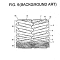
reference numeral 80. Eachrotor 80 has an inlet opening 82, a changinglead portion 85, andconstant lead portions inlet opening 82 is formed in the end face of therotor 80 adjacent to an inlet port. Lead angle of the changinglead portion 85 of therotor 80 decreases from the end face thereof toward theconstant lead portion 84. Lead angles of theconstant lead portions rotors 80 and a housing of the displacement machine (not shown) define an inlet space P and a plurality of closed pump spaces S. The inlet space P is in communication with the inlet port through the inlet opening 82, so that fluid is drawn into the inlet space P during the rotation of therotors 80. The closed pump spaces S are formed adjacent to the inlet space P. The inlet space P changes its volume while therotors 80 make a complete one turn, and the inlet space P is transferred to a pump space S when therotors 80 have completed the one turn. - In this case, when the
rotors 80 have completed the one turn, the fluid in the inlet space P is transferred to the pump space S. Thus, the volume of fluid of the closed pump space S is the fluid volume to be transferred in the screw pump. If the lead angle of therotor 80 is constant, the fluid volume of the inlet space P remains substantially constant without a change during the rotation of therotors 80. That is, the fluid volume of the pump space S after rotation of therotors 80 substantially coincides with that of the inlet space P before rotation of therotors 80. - In the above conventional art, however, the volume of fluid of the closed pump space substantially is the volume to be transferred. The inlet space which is formed by the first one turn of the lead and in communication with the inlet port does not provide fluid compression. Merely setting the volume of the inlet space larger than that of the pump space will not improve the efficiency of drawing in the fluid into the inlet space, In addition, the conventional art wherein the volume of the inlet space is not effectively used, the rotor need to be lengthened in order to improve the efficiency of drawing in the fluid into the inlet space.
- The present invention is directed to a screw pump wherein the inlet space which is provided by the first one turn of the lead is utilized for fluid transferring thereby to increase the volume of fluid to be transferred in the screw pump.
- In accordance with an aspect of the present invention, a screw pump includes a housing and a pair of screw rotors. The housing has an inlet port for allowing fluid to be drawn therethrough into the housing, and an outlet port for allowing the fluid to be delivered therethrough out of the housing. The screw rotors are rotatably disposed in the housing in engagement with each other. An end face of the rotor adjacent to the inlet port is provided with an inlet opening. Each rotor has a first portion whose lead angle changes. The first portions and the housing cooperate to form an inlet space which is in communication with the inlet port through the inlet openings for allowing the fluid to be drawn into the inlet space and whose volume is variable in accordance with the rotation of the rotors, During the rotation of the rotors, the communication between the inlet space and the inlet port is blocked by the first portions and the housing thereby to form a closed pump space adjacent to the inlet space. When the communication between the inlet space and the inlet port is blocked to form the closed pump space, a position of the rotors is defined as a starting position of one turn of the rotors. The inlet space changes its volume and its volume becomes the maximum in the range from the starting position to less than one turn of the rotors. Volume of the pump space is set smaller than the maximum volume of the inlet space by setting the lead angle of the first portions. A closure member is provided which covers at least a part of the inlet openings. The closure member closes the inlet space when the volume of the inlet space exceeds that of the pump space.
- Other aspects and advantages of the invention will become apparent from the following description, taken in conjunction with the accompanying drawings, illustrating by way of example the principles of the invention.
- The features of the present invention that are believed to be novel are set forth with particularity in the appended claims. The invention together with objects and advantages thereof, may best be understood by reference to the following description of the presently preferred embodiments together with the accompanying drawings in which:
- FIG. 1 is a longitudinal sectional view showing a screw pump according to a first embodiment of the present invention;
- FIG. 2 is a cross sectional view taken along the line 2-2 of FIG. 1;
- FIG. 3 is a front view showing a pair of intermeshing rotors of the screw pump;
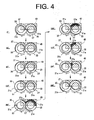
- FIG. 4 is a schematic plan view showing the movement of end faces of the rotors adjacent to an inlet port during one turn of the rotors;
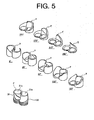
- FiG. 5 is a perspective view showing an inlet space which changes its volume during one turn of the rotors;
- FIG 6 is a graph showing the change of the volume of the inlet space during one turn of the rotors;
- FIG. 7 is a front view showing a pair of intermeshing rotors of a screw pump according to a second embodiment of the present invention;
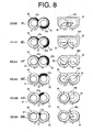
- FIG. 8 is a plan view showing closure regions of the inlet openings at different turned positions of the rotors and the closure members for accomplishing the closure regions of the inlet openings; and
- FIG., 9 is a front view showing a pair of intermeshing rotors of a conventional screw pump.
- The following will describe a screw pump according to a first embodiment of the present invention with reference to FIGs. 1 to 6. FIG, 1 is a longitudinal sectional view showing a screw pump of the first embodiment, and FIG 2 is a cross sectional view taken along the line 2-2 of FIG 1. Referring to FIG. 1, the
screw pump 11 is of a vertical type and used as a vacuum pump in the process of manufacturing semiconductors. Thescrew pump 11 includes agear case 12, arotor housing 14, anupper housing 16, a pair of intermeshingscrew rotors cover plate 40. Therotor housing 14 has a cylindrical shape and is joined to the upper end of thegear case 12. Theupper housing 16 has a flat shape and is joined to the upper end of therotor housing 14. Therotors rotor housing 14. Thecover plate 40 has a rectangular shape and is fixed to the inner wall of therotor housing 14. Thecover plate 40 serves as a closure member. - The
gear case 12 houses therein anelectric motor 13 for driving thescrew pump 11, a pair ofintermeshing gears coupling 24. Thegears rotors coupling 24 is operable to transmit torque of theelectric motor 13 to therotors electric motor 13. Therotor housing 14 forms a space whose shape corresponds to the shape of theintermeshing rotors outlet port 15 is formed in therotor housing 14 at a position adjacent to thegear case 12, through which the space in therotor housing 14 communicates with an external fluid circuit (not shown), so that the fluid in thescrew pump 11 is delivered to the external fluid circuit through theoutlet port 15. Therotor housing 14 and thegear case 12 are joined to each other by a fixing member such as a bolt (not shown). - The
upper housing 16 closes the upper end of therotor housing 14. Aninlet port 17 is formed through the center of theupper housing 16. Through theinlet port 17 the space for therotors screw pump 11 through theinlet port 17. - The
rotors rotor 20 is the drive rotor while therotor 30 is the driven rotor. Thedrive rotor 20, the drivenrotor 30 and therotor housing 14 cooperate to form a plurality of working chambers, or pump spaces, through which the fluid is transferred from theinlet port 17 to theoutlet port 15 while being compressed. - The
drive rotor 20 will now be described more in detail. Thedrive rotor 20 is driven to be rotated by theelectric motor 13. Thedrive rotor 20 is mounted on adrive shaft 22 which extends out into thegear case 12. Thegear 23 as a drive gear is mounted on thedrive shaft 22 for rotation therewith in thegear case 12. Thedrive shaft 22 is rotatably supported by thegear case 12 through a bearing (not shown) and connected at the bottom end thereof to thecoupling 24, which is in turn connected to theelectric motor 13. Thedrive gear 23 engages with thegear 33 as a driven gear which is provided on the drivenrotor 30 for transmitting torque of thedrive rotor 20 to the drivenrotor 30. - The
drive rotor 20 is of a single-start thread having a helical thread and a thread groove. As shown in FIG 3, thedrive rotor 20 has afirst portion 25 and asecond portion 26. Thefirst portion 25 is formed extending from the end of thedrive rotor 20 adjacent to theinlet port 17 to the vicinity of theoutlet port 15. Thesecond portion 26 is formed extending continuously from thefirst portion 25 to the end of thedrive rotor 20 facing thegear case 12, As shown in FIG 3, a lead angle of the first portion 25 (i.e. an angle made between a plane that is perpendicular to the axes of rotation of therotors drive rotor 20 adjacent to theinlet port 17 toward theoutlet port 15, While thesecond portion 26 has a constant lead angle. Therefore, the lead angle of thefirst portion 25 of thedrive rotor 20 is the maximum at the end of thedrive rotor 20 adjacent to theinlet port 17. - On the other hand, the lead angle of the
second portion 26 of thedrive rotor 20 is constant and set smaller than the minimum lead angle of thefirst portion 25. The end face of thedrive rotor 20 adjacent to theinlet port 17, which is designated byreference character 21 a, is perpendicular to the rotary axis of thedrive rotor 20. As shown in FiG. 2, the end face 21 a is formed with aninlet opening 27 at which the thread groove starts. - The driven
rotor 30 will now be described. The drivenrotor 30 is rotated with thedrive rotor 20. The drivenrotor 30 is mounted on a drivenshaft 32. Uke thedrive rotor 20, the drivenrotor 30 is of a single-start thread having a helical thread and a thread groove. As shown in FIG. 3, the drivenrotor 30 has afirst portion 35 and asecond portion 36. As shown in FIG. 2, anend face 31 a of the drivenrotor 30 adjacent to theinlet port 17 is provided with aninlet opening 37. As indicated earlier herein, therotors rotors first portions rotor housing 14 cooperate to form an inlet space P at the end of thefirst portions rotors inlet port 17. The inlet space P is in communication with theinlet openings rotors inlet port 17 through theinlet openings rotors inlet port 17 is blocked by therotor housing 14 and therotors - When the communication between the inlet space P and the
inlet port 17 is just blocked thereby to form the pump space S, the position of therotors rotors rotation angle 0° of therotors rotors intermeshing rotors inlet port 17, showing changes of intermeshing relation of therotors rotation angle 0°) until therotors rotation angle 360°). The inlet space P changes its volume and its volume becomes the maximum during one complete turn of therotors rotors 20, 30 (on the horizontal axis) and the volume of the inlet space P (on the vertical axis). The rotation angle of therotors first portions first portions - As mentioned above, a plurality of closed pump spaces S are formed on the side adjacent to the inlet space P, as shown in FIG. 1, The pump space S located nearest to the inlet space P is a space into which the fluid in the inlet space P is transferred after the
rotors rotors rotors first portions rotors second portions rotors second portions - The
cover plate 40 will now be described. Therotors cover plate 40 is fixed to the inner wall of therotor housing 14 so as to partially cover the end faces 21 a, 31 a of therotors cover plate 40 to therotor housing 14. As shown in FIG. 2, thecover plate 40 of the present embodiment is adapted to cover about a half of the end face 21 a and about a quarter of the end face 31 a. An engaging point between therotors cover plate 40 is arranged so as to cover part of the end faces 21 a, 31 a in the region which is coming to reach the engaging point G, as shown in FIG. 2. In other word, thecover plate 40 covers a part of theinlet openings rotors rotor housing 14 and thecover plate 40. The closed inlet space P contributes to increase the volume of fluid to be transferred by therotors screw pump 11 is improved. - In the present embodiment, the end faces 21a, 31a of the
rotors upper housing 16 at a predetermined distance so that aninlet chamber 18 is formed in therotor housing 14 in facing relation to the end faces 21 a, 31 a of therotors - The following will now describe the operation of the above-described embodiment of the
screw pump 11. The inlet space P of thescrew pump 11 of the present preferred embodiment changes its volume during one complete turn of therotors rotors inlet chamber 18 through theinlet openings rotors inlet chamber 18 to be drawn into the inlet space P through theinlet openings - When the
rotors inlet openings inlet chamber 18 by thecover plate 40. For the sake of explanatory convenience, such part of theinlet openings inlet chamber 18 will be referred to asclosure regions closure regions inlet openings cover plate 40, therotors rotor housing 14 define the closed inlet space P which does not communicate with theinlet chamber 18 through theinlet openings rotors closure regions inlet openings rotation angle 360° is reached, the inlet space P is transferred to a pump space S. At the same time, a new inlet space P is formed at the inlet end of therotors - In the present embodiment, there exists a closed inlet space P at the rotation angle of 180°. Compared to the conventional case where the inlet space P is constantly in communication with the inlet chamber 18 (or the inlet port 17) until the inlet space P is transferred to the pump space S, the volume of fluid enclosed in the pump space S is increased in the present embodiment. Referring to the graph in FIG. 6, the increase of the volume of the fluid is designated by ΔL. The increase of fluid volume ΔL corresponds to the difference between the volume Lp of the inlet space P and the volume Ls of the pump space S. That is, when the inlet space P is constantly in communication with the inlet chamber 18 (or the inlet port 17) until the inlet space P is transferred to the pump space S, the volume of fluid enclosed in the pump space S corresponds to the volume Ls. When the inlet space P is closed at the
rotation angle 180°, on the other hand, the volume of fluid enclosed in the closed inlet space P corresponds to the volume Lp. The change of volume of the inlet space P is shown in FIG. 5. The inlet space P is transferred to a pump space S after therotors - After the complete turn of the
rotors rotors rotors rotors outlet port 15 successively through thefirst portions second portions outlet port 15. Thesecond portions rotors first portions - The screw pump of the first embodiment has the following advantageous effects.
- (1) According to the preferred embodiment of screw pump, the
cover plate 40 covers part of theinlet openings screw pump 11 is improved and the performance of thescrew pump 11 is improved, accordingly. - (2) Since the volume of fluid to be transferred is increased by the differential ΔL between the volume Lp of the closed inlet space P and the volume Ls of the pump space S, axial length of the
rotors screw pump 11 to be reduced. - (3) Since the
cover plate 40 closes the inlet space P at 1/2 turn of therotors inlet port 17 is ensured at least in the range from the state where the inlet space P starts to be formed (or the position of therotation angle 0°) to 1/2 turn position of therotors - (4) The inlet space P is closed before the
rotors first portions rotors screw pump 11. - (5) Compared with a case where the cover plate is integral with the housing of the screw pump, replacement of the
cover plate 40 and relocation thereof relative to therotors rotors - (6) Providing the
second portions rotors rotors second portions first portions second portions - The following will describe a screw pump according to a second embodiment of the present invention with reference to FIGs. 6 and 7. The screw pump of the present embodiment is substantially the same as that of the first embodiment except that the structure of the rotors differs from that of the first embodiment. Therefore, description of common elements or parts of the screw pump will be omitted and the reference symbols used for description of the first embodiment will be used to denote the common elements.
- Referring to FIG, 7, the
screw pump 51 of the present embodiment includes adrive rotor 60 and a drivenrotor 70. Therotors first portions second portions third portions first portions inlet port 17. Thethird portions rotors rotors third portions first portions third portions second portions - The
third portions first portions rotors rotors rotors rotors third portions rotors rotors rotors first portions second portions first portions second portions cover plate 40 is provided to cover about a half of the end face 61 a of thedrive rotor 60, about a quarter of theend face 71a of the drivenrotor 70 and a part of inlet opening (not shown) provided on the end faces 61 a, 71 a. - According to the present embodiment, the inlet space P has the maximum volume at the position of the
rotors cover plate 40, so that thecover plate 40, therotors rotor housing 14 define a closed inlet space P. As shown by pattern B curve in FIG 6, the inlet space P of the present embodiment changes its volume. - The screw pump of the second embodiment has substantially the same effects as those (1)-(6) of the first embodiment. In addition, the present second embodiment in which the
cover plate 40 closes the inlet space P when the volume of the inlet space P becomes the maximum utilizes the inlet space P most effectively. Furthermore, since thethird portions rotors rotors rotors rotors cover plate 40 at an appropriate time in accordance with the driving condition of thescrew pump 51. - The present invention is not limited to the above first and second embodiments, but may be practiced in various ways within the scope of the invention,
- In the above first and second embodiments, the cover plate forms the closure region in the inlet opening when the
rotors rotors - In the above first and second embodiments, the cover plate is disclosed as the closure member for forming the closure region in the inlet opening at the time of 1/2 turn. However, the shape of the cover plate may be changed in accordance with the desired time at which the
inlet openings closure regions inlet openings rotors closure regions inlet openings inlet openings - Although in the above first and second embodiments the inlet chamber is provided in the housing, the rotor housing may have the function of the cover plate (closure member) without providing an inlet chamber in the housing. In this case, the cover plate helps to reduce the number of parts of the screw pump.
- ln the above first and second embodiments, lead angle of the first portions of the rotors decreases from the inlet end thereof toward the opposite outlet end. However, the lead angle of the first portions need not necessarily decrease, but it may increase or combination of increasing and decreasing leads may be used.
- Although in the above first and second embodiments the screw pump is of a vertical type wherein the axes of rotors thereof are vertically arranged, the present invention is also applicable to screw pumps having the axes of the rotors thereof disposed otherwise.
- Although the screw pump in the above first and second embodiments has a screw rotor with a single-start thread, the number of threads is not limited. For example, a screw rotor with a double-start thread may be employed. In addition, the number of helical threads and thread grooves of the rotors may be determined appropriately.
- It is noted that a screw pump having rotors whose inlet space becomes maximum in volume only after the rotors have made one complete turn from the starting position thereof, (the maximum volume of the inlet space not exceeding the volume of a pump space,) will be excluded from the scope of the present invention. This is because the volume of fluid to be transferred in the screw pump will not be increased as long as the volume of fluid in the inlet space does not exceed the volume of fluid in the pump space, no matter where the inlet space is sealed. That is, if the inlet space is closed by the cover plate (or closure member) in a screw pump in which the volume of fluid in the inlet space P does not exceed that in the pump space S, the volume of fluid to be transferred is decreased, with the result that the working efficiency of the screw pump will be reduced. Therefore, the present invention is applicable to a screw pump wherein the fluid volume of the inlet space exceeds that of the pump space.
- Therefore, the present examples and embodiments are to be considered as illustrative and not restrictive, and the invention is not to be limited to the details given herein but may be modified within the scope of the appended claims.
A screw pump includes a housing and a pair of intermeshing screw rotors. An end face of the rotor adjacent to an inlet port of the housing is provided with an inlet opening. Each rotor has a first portion whose lead angle changes. The first portions and the housing cooperate to form an inlet space. During rotation of the rotors, communication between the inlet space and the inlet port is blocked by the first portions and the housing thereby to form a closed pump space adjacent to the inlet space. Volume of the pump space is set smaller than the maximum volume of the inlet space. A closure member is provided which covers at least a part of the inlet openings. The closure member closes the inlet space when the volume of the inlet space exceeds that of the pump space.
Claims (10)
- A screw pump (11, 51) comprising:a housing (12, 14, 16) having an inlet port (17) for allowing fluid to be drawn therethrough into the housing (12, 14, 16), and an outlet port (15) for allowing the fluid to be delivered therethrough out of the housing (12, 14, 15); anda pair of screw rotors (20, 30, 60, 70) rotatably disposed in the housing (12, 14, 16) in engagement with each other, an end face (21a. 31 a, 61a, 71 a) of the rotor (20, 30, 50, 70) adjacent to the inlet port (17) being provided with an inlet opening (27, 37), each rotor (20, 30, 60, 70) having a first portion (25, 35, 65, 75) whose lead angle changes,wherein the first portions (25, 35, 65, 75) and the housing (12, 14, 16) cooperate to form an inlet space (P) which is in communication with the inlet port (17) through the inlet openings (27, 37) for allowing the fluid to be drawn into the inlet space (P) and whose volume is variable in accordance with the rotation of the rotors (20, 30, 60, 70),
wherein during the rotation of the rotors (20, 30, 60, 70), the communication between the inlet space (P) and the inlet port (17) is blocked by the first portions (25, 35, 65, 75) and the housing (12, 14, 16) thereby to form a closed pump space (S) adjacent to the inlet space (P),
wherein when the communication between the inlet space (P) and the inlet port (17) is blocked to form the closed pump space (S), a position of the rotors (20, 30, 60, 70) is defined as a starting position of one turn of the rotors (20, 30, 60, 70), characterized in that
the inlet space (P) changes its volume and its volume becomes the maximum in the range from the starting position to less than one turn of the rotors (20, 30, 60, 70), wherein volume of the pump space (S) is set smaller than the maximum volume of the inlet space (P) by setting the lead angle of the first portions (25, 35, 65, 75), wherein a closure member (40, 401-406) is provided which covers at least a part (27a, 37a) of the inlet openings (27, 37), and wherein the closure member (40, 401-406) closes the inlet space (P) when the volume of the inlet space (P) exceeds that of the pump space (S). - The screw pump (11, 51) according to claim 1, wherein the closure member (40, 401-406) has such a shape as to close the inlet space (P) in a range between a position corresponding to 1/8 turn of the rotors (20, 30, 60, 70) from the starting position and a position corresponding to one turn of the rotors (20, 30, 60, 70) from the starting position, exclusive of the position of the one turn.
- The screw pump (11, 51) according to claim 1 or 2, wherein the closure member (40, 401-406) has such a shape as to close the inlet space (P) substantially at a position corresponding to 1/2 turn of the rotors (20, 30, 60, 70) from the starting position.
- The screw pump (11, 51) according to any one of claims 1 through 3,
wherein the closure member (40, 401-406) has such a shape as to close the inlet space (P) when the volume of the inlet space (P) becomes the maximum. - The screw pump (11, 51) according to any one of claims 1 through 4,
wherein the closure member (40, 401-406) is separate from the housing (12, 14, 16) and is removably mounted on the housing (12, 14, 16). - The screw pump (11, 51) according to any one of claims 1 through 5,
wherein each rotor (20, 30, 60, 70) has a second portion (26, 36, 66, 76) which is formed continuously from the first portion (25, 35; 65, 75) toward an outlet port (15), and wherein lead angle of the second portion (26, 36, 66, 76) is constant and set smaller than that of the first portion (25. 35, 65, 75). - The screw pump (11, 51) according to any one of claims 1 through 6,
wherein each rotor (20, 30, 60, 70) has a third portion (67,77) which is located from the first portion (25, 35, 65, 75) toward the inlet port (17), the third portion (67, 77) being formed in a region from the end face (21 a, 31a, 61a, 71a) of the rotor (20, 30, 60, 70) to a position between a point corresponding to 1/2 turn of the rotors (20, 30, 60, 70) from the starting position and a point before the one turn of the rotors (20, 30, 60, 70) from the starting position, lead angle of the third portion (67, 77) being set smaller than that of the first portion (25, 35, 65, 75). - The screw pump (11, 51) according to any one of claims 1 through 7,
wherein the lead angle of the first portion (25, 35, 65, 75) decreases progressively from the end on the rotor (20, 30, 60, 70) adjacent to the inlet port (17) toward the outlet port (15). - The screw pump (11. 51) according to any one of claims 1 through 8,
wherein the closure member (40, 401-406) is a cover plate. - The screw pump (11, 51) according to any one of claims 1 through 9,
wherein each rotor (20, 30,60, 70) is of a single-start thread.
Applications Claiming Priority (1)
| Application Number | Priority Date | Filing Date | Title |
|---|---|---|---|
| JP2006217853A JP4853168B2 (en) | 2006-08-10 | 2006-08-10 | Screw pump |
Publications (2)
| Publication Number | Publication Date |
|---|---|
| EP1890038A2 true EP1890038A2 (en) | 2008-02-20 |
| EP1890038A3 EP1890038A3 (en) | 2013-09-04 |
Family
ID=38656985
Family Applications (1)
| Application Number | Title | Priority Date | Filing Date |
|---|---|---|---|
| EP07114086.7A Withdrawn EP1890038A3 (en) | 2006-08-10 | 2007-08-09 | Screw pump |
Country Status (5)
| Country | Link |
|---|---|
| US (1) | US7497672B2 (en) |
| EP (1) | EP1890038A3 (en) |
| JP (1) | JP4853168B2 (en) |
| KR (1) | KR100923039B1 (en) |
| TW (1) | TWI336371B (en) |
Cited By (2)
| Publication number | Priority date | Publication date | Assignee | Title |
|---|---|---|---|---|
| WO2013152112A1 (en) * | 2012-04-05 | 2013-10-10 | Eaton Corporation | Rotary blower with variable inlet port geometry |
| CN108443145A (en) * | 2018-05-22 | 2018-08-24 | 天津华科螺杆泵技术有限公司 | A kind of twin-feed spiral screw rod and Quimby pump and dry vacuum screw pump using the screw rod |
Families Citing this family (8)
| Publication number | Priority date | Publication date | Assignee | Title |
|---|---|---|---|---|
| US20080193316A1 (en) * | 2007-02-08 | 2008-08-14 | Kabushiki Kaisha Toyota Jidoshokki | Roots pump |
| US20090288648A1 (en) * | 2008-05-21 | 2009-11-26 | Gm Global Technology Operations, Inc. | Superchargers with dual integral rotors |
| WO2010103701A1 (en) * | 2009-03-09 | 2010-09-16 | 古河産機システムズ株式会社 | Uniaxial eccentric screw pump |
| JP5353521B2 (en) * | 2009-07-22 | 2013-11-27 | 株式会社豊田自動織機 | Screw rotor |
| DE102014102390B3 (en) * | 2014-02-25 | 2015-03-26 | Leistritz Pumpen Gmbh | Screw Pump |
| DE102017210771B4 (en) * | 2017-06-27 | 2019-05-29 | Continental Automotive Gmbh | Screw pump, fuel delivery unit and fuel delivery unit |
| EP3499041B1 (en) * | 2017-12-15 | 2020-07-01 | Pfeiffer Vacuum Gmbh | Screw vacuum pump |
| CN108194355A (en) * | 2018-03-05 | 2018-06-22 | 珠海格力电器股份有限公司 | Compressor and air conditioning equipment |
Family Cites Families (12)
| Publication number | Priority date | Publication date | Assignee | Title |
|---|---|---|---|---|
| GB648055A (en) * | 1947-11-19 | 1950-12-28 | Imo Industri Ab | Improvements in screw compressors and motors |
| US3108740A (en) * | 1960-06-17 | 1963-10-29 | Svenska Rotor Maskiner Ab | Regulating means for rotary piston compressors |
| JPS55153881A (en) | 1979-04-24 | 1980-12-01 | Anretsuto:Kk | Helical type double-axle rotary fluid pump |
| JPH0518382A (en) * | 1991-07-10 | 1993-01-26 | Ebara Corp | Screw vacuum pump |
| JP2537712B2 (en) * | 1991-07-10 | 1996-09-25 | 株式会社荏原製作所 | Screw type vacuum pump |
| JPH0518381A (en) * | 1991-07-10 | 1993-01-26 | Ebara Corp | Screw vacuum pump |
| JPH06288369A (en) * | 1993-04-06 | 1994-10-11 | Hitachi Ltd | Suction port of screw compressor |
| DE59603493D1 (en) * | 1995-06-21 | 1999-12-02 | Sterling Ind Consult Gmbh | VACUUM PUMP |
| JP3704542B2 (en) * | 1997-05-12 | 2005-10-12 | ナブテスコ株式会社 | Screw type vacuum pump and screw processing machine |
| ATE266800T1 (en) | 1998-10-23 | 2004-05-15 | Busch Sa Atel | TWIN CONVEYOR SCREW ROTORS |
| DE59909182D1 (en) * | 1999-07-19 | 2004-05-19 | Sterling Fluid Sys Gmbh | Displacement machine for compressible media |
| JP2004263629A (en) * | 2003-03-03 | 2004-09-24 | Tadahiro Omi | Screw vacuum pump |
-
2006
- 2006-08-10 JP JP2006217853A patent/JP4853168B2/en not_active Expired - Fee Related
-
2007
- 2007-08-07 TW TW096128948A patent/TWI336371B/en not_active IP Right Cessation
- 2007-08-08 KR KR1020070079773A patent/KR100923039B1/en not_active Expired - Fee Related
- 2007-08-09 US US11/891,531 patent/US7497672B2/en not_active Expired - Fee Related
- 2007-08-09 EP EP07114086.7A patent/EP1890038A3/en not_active Withdrawn
Cited By (2)
| Publication number | Priority date | Publication date | Assignee | Title |
|---|---|---|---|---|
| WO2013152112A1 (en) * | 2012-04-05 | 2013-10-10 | Eaton Corporation | Rotary blower with variable inlet port geometry |
| CN108443145A (en) * | 2018-05-22 | 2018-08-24 | 天津华科螺杆泵技术有限公司 | A kind of twin-feed spiral screw rod and Quimby pump and dry vacuum screw pump using the screw rod |
Also Published As
| Publication number | Publication date |
|---|---|
| KR100923039B1 (en) | 2009-10-22 |
| US20080038137A1 (en) | 2008-02-14 |
| KR20080014642A (en) | 2008-02-14 |
| EP1890038A3 (en) | 2013-09-04 |
| JP4853168B2 (en) | 2012-01-11 |
| US7497672B2 (en) | 2009-03-03 |
| JP2008038861A (en) | 2008-02-21 |
| TWI336371B (en) | 2011-01-21 |
| TW200821472A (en) | 2008-05-16 |
Similar Documents
| Publication | Publication Date | Title |
|---|---|---|
| US7497672B2 (en) | Screw pump with increased volume of fluid to be transferred | |
| US8556607B2 (en) | Screw rotor | |
| US7484943B2 (en) | Screw pump with improved efficiency of drawing fluid | |
| EP0302877B1 (en) | Rotary positive displacement machine for a compressible working fluid | |
| EP2597311B1 (en) | Single Screw Compressor With High Output | |
| JP4404115B2 (en) | Screw compressor | |
| CN103541899B (en) | Screw compressor | |
| JP4900270B2 (en) | Screw pump | |
| EP1655491A2 (en) | Screw pump | |
| CN102575673A (en) | Dry screw driver | |
| KR101315842B1 (en) | Vacuum pump with screw rotor | |
| US20080193316A1 (en) | Roots pump | |
| EP0276252B1 (en) | Screw rotor compressor | |
| EP2039936A1 (en) | Scroll compressor | |
| JPH1182350A (en) | Oil pump of compressor | |
| KR20060047511A (en) | Screw fluid machine | |
| WO2010150388A1 (en) | Gear pump | |
| JP2025029344A (en) | Liquid-feed screw compressor | |
| JPH041353Y2 (en) | ||
| JPS6153482A (en) | Trochoidal pump for engine lubricatioin | |
| WO2008088269A1 (en) | Screw compressor | |
| JP2005113813A (en) | Screw type compressor | |
| KR20070023781A (en) | Screw pump and screw gear | |
| JPH07158580A (en) | Horizontal type scroll compressor |
Legal Events
| Date | Code | Title | Description |
|---|---|---|---|
| PUAI | Public reference made under article 153(3) epc to a published international application that has entered the european phase |
Free format text: ORIGINAL CODE: 0009012 |
|
| 17P | Request for examination filed |
Effective date: 20070809 |
|
| AK | Designated contracting states |
Kind code of ref document: A2 Designated state(s): AT BE BG CH CY CZ DE DK EE ES FI FR GB GR HU IE IS IT LI LT LU LV MC MT NL PL PT RO SE SI SK TR |
|
| AX | Request for extension of the european patent |
Extension state: AL BA HR MK YU |
|
| PUAL | Search report despatched |
Free format text: ORIGINAL CODE: 0009013 |
|
| AK | Designated contracting states |
Kind code of ref document: A3 Designated state(s): AT BE BG CH CY CZ DE DK EE ES FI FR GB GR HU IE IS IT LI LT LU LV MC MT NL PL PT RO SE SI SK TR |
|
| AX | Request for extension of the european patent |
Extension state: AL BA HR MK RS |
|
| RIC1 | Information provided on ipc code assigned before grant |
Ipc: F04C 18/16 20060101AFI20130726BHEP Ipc: F04C 25/02 20060101ALI20130726BHEP Ipc: F01C 21/10 20060101ALI20130726BHEP Ipc: F04C 29/12 20060101ALI20130726BHEP Ipc: F04C 18/08 20060101ALI20130726BHEP |
|
| AKX | Designation fees paid |
Designated state(s): AT BE BG CH CY CZ DE DK EE ES FI FR GB GR HU IE IS IT LI LT LU LV MC MT NL PL PT RO SE SI SK TR |
|
| STAA | Information on the status of an ep patent application or granted ep patent |
Free format text: STATUS: THE APPLICATION IS DEEMED TO BE WITHDRAWN |
|
| 18D | Application deemed to be withdrawn |
Effective date: 20140305 |