EP1890007A2 - High lift transonic turbine blade - Google Patents
High lift transonic turbine blade Download PDFInfo
- Publication number
- EP1890007A2 EP1890007A2 EP07253094A EP07253094A EP1890007A2 EP 1890007 A2 EP1890007 A2 EP 1890007A2 EP 07253094 A EP07253094 A EP 07253094A EP 07253094 A EP07253094 A EP 07253094A EP 1890007 A2 EP1890007 A2 EP 1890007A2
- Authority
- EP
- European Patent Office
- Prior art keywords
- blade
- airfoil
- support surface
- nominal
- values
- Prior art date
- Legal status (The legal status is an assumption and is not a legal conclusion. Google has not performed a legal analysis and makes no representation as to the accuracy of the status listed.)
- Withdrawn
Links
- 238000010606 normalization Methods 0.000 claims description 17
- 239000012530 fluid Substances 0.000 description 11
- 239000011248 coating agent Substances 0.000 description 3
- 238000000576 coating method Methods 0.000 description 3
- 238000004519 manufacturing process Methods 0.000 description 3
- 238000010586 diagram Methods 0.000 description 2
- 230000001133 acceleration Effects 0.000 description 1
- 238000006243 chemical reaction Methods 0.000 description 1
- 238000001816 cooling Methods 0.000 description 1
- 230000005484 gravity Effects 0.000 description 1
- 230000035939 shock Effects 0.000 description 1
- 238000011144 upstream manufacturing Methods 0.000 description 1
Images



Classifications
-
- F—MECHANICAL ENGINEERING; LIGHTING; HEATING; WEAPONS; BLASTING
- F01—MACHINES OR ENGINES IN GENERAL; ENGINE PLANTS IN GENERAL; STEAM ENGINES
- F01D—NON-POSITIVE DISPLACEMENT MACHINES OR ENGINES, e.g. STEAM TURBINES
- F01D5/00—Blades; Blade-carrying members; Heating, heat-insulating, cooling or antivibration means on the blades or the members
- F01D5/12—Blades
- F01D5/14—Form or construction
- F01D5/141—Shape, i.e. outer, aerodynamic form
-
- F—MECHANICAL ENGINEERING; LIGHTING; HEATING; WEAPONS; BLASTING
- F05—INDEXING SCHEMES RELATING TO ENGINES OR PUMPS IN VARIOUS SUBCLASSES OF CLASSES F01-F04
- F05D—INDEXING SCHEME FOR ASPECTS RELATING TO NON-POSITIVE-DISPLACEMENT MACHINES OR ENGINES, GAS-TURBINES OR JET-PROPULSION PLANTS
- F05D2240/00—Components
- F05D2240/80—Platforms for stationary or moving blades
-
- F—MECHANICAL ENGINEERING; LIGHTING; HEATING; WEAPONS; BLASTING
- F05—INDEXING SCHEMES RELATING TO ENGINES OR PUMPS IN VARIOUS SUBCLASSES OF CLASSES F01-F04
- F05D—INDEXING SCHEME FOR ASPECTS RELATING TO NON-POSITIVE-DISPLACEMENT MACHINES OR ENGINES, GAS-TURBINES OR JET-PROPULSION PLANTS
- F05D2250/00—Geometry
- F05D2250/70—Shape
- F05D2250/74—Shape given by a set or table of xyz-coordinates
Definitions
- the present invention relates to turbine blades for turbomachinery such as gas turbine engines and, more particularly, to improved geometrical shapes for such blades and the platform from which they extend.
- Turbine blades are mounted circumferentially on an inner diameter platform about a turbine shaft to allow rotation thereof in streams of working medium fluids to extract energy and work therefrom as those fluids flow around and past such blades through the flow passages between them.
- Such flows can be transonic in accelerating from below the speed of sound coming into the blade region to being above the speed of sound in the exit region. In these situations inefficiencies due to shock wave losses are important.
- Blade airfoil surface profiles, and the geometry of the airfoil and the platform on which the blade is mounted become very important in achieving high efficiencies.
- a blade design to be suitable must minimize the penalties imposed on the engine system by the weight and cost of the blades, and need for cooling air therein, a goal sought through reducing the number of blades provided about the platform circumference for each blade stage used. However, the remaining blades must then extract more work, the lift or loading of the blade, from the fluid streams passing thereby which tends to reduce blade efficiency.
- a high lift blade will have a Zweifel lift coefficient (the ratio of the actual load to the ideal load) that is greater than 1.1.
- a blade that achieves high efficiency during transonic operation while having a large lift loading is a blade that achieves high efficiency during transonic operation while having a large lift loading.
- the present invention provides a turbine blade system including a blade airfoil having an airfoil shape with the blade airfoil having a nominal profile substantially in accordance with normalized Cartesian coordinate values of X, Y and Z set forth in Table 1 below and which values are dimensionless values that are convertible to corresponding absolute distance values through manipulating them in accord with corresponding normalization equations.
- the X and Y absolute distance values when connected by smooth continuing arcs, define nominal airfoil profile sections at each Z absolute distance value, and these nominal airfoil profile sections, when joined smoothly with adjacent ones thereof, form a complete nominal airfoil shape that is substantially matched by the airfoil shape of the blade airfoil.
- This blade airfoil can be supported on a ring platform having a support surface with a support surface shape in the vicinity of the location at which that blade airfoil is supported thereon such that the support surface smoothly joins with the airfoil shape of that blade airfoil, the support surface having a nominal profile substantially in accordance with normalized Cartesian coordinate values of X, Y and Z set forth in Table 4 below and which values are dimensionless values that are convertible to corresponding absolute distance values through manipulating them in accord with corresponding normalization equations, and wherein X and Y absolute distance values at various Z absolute distance values, when connected by smooth continuing arcs, form a nominal support surface shape substantially matched by the support surface shape of the support surface.
- Figure 1 shows the relationship of a blade, 10, mounted on a rotatable platform extending about an unseen turbine shaft adjacent a fluid guide vane, 11. Above them is shown the edge of the engine wall limiting the outer extent of the fluid flow path past blade 10 and vane 11, that is, forming the outer diameter, of this fluid flow passage containing blade 10 and vane 11.
- Rotatable blade 10 has a gap, 13, between the tip of that blade and outer diameter 12 but vane 11 is fixed to the structure providing this fluid flow passageway outer diameter as well as to the structure supporting it from below. That vane supporting structure and the platform on which blade 10 is mounted together limit the inner extent of the fluid flow path past blade 10 and vane 11, that is, forming the inner diameter, 12, of this fluid flow passage containing blade 10 and vane 11.
- Blade 10 is shown having an outward extent from the platform on which it is mounted to its tip designated as its span, 15.
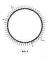
- Blade 10 and the inner diameter 12 surface of the platform on which blade 10 is mounted of the present invention are shown in the pictorial perspective view of Figure 2, and a plurality of blades 10 so mounted are shown in Figure 3 circumferentially positioned about the rotatable ring platform supporting them on which the inner diameter surface 14 of the fluid passageway is indicated. Sixty such blades are so provided on the ring platform example shown in Figure 3. In addition to what is shown in Figures 2 and 3, blades 10 can be positioned through being selectively rotated about a radial axis extending outward from the engine centerline from what is shown by up to about ⁇ 10°.
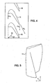
- Figure 4 shows a diagrammatic top view of a portion of the platform ring in Figure 3 with certain variables marked thereon used in calculating the Zweifel lift coefficient for blades 10.
- FIG. 5 A perspective diagram of the blade of Figure 2 is shown in Figure 5 with the three dimensional coordinates, X, Y and Z, of a Cartesian coordinate system shown that will be used in providing a description of the geometry of the blade, and surface of the platform supporting that blade, that is, a description of the shapes involved.
- the shape of blade 10 of the present invention can be specified using an outwardly stacked, or radially stacked, series of cross section portions of that blade, stacked along its span 15 extending outward from the ring center as indicated in Figure 6, with the radial axis extending perpendicular to the engine centerline (and so the platform ring centerline) being designated the Z axis shown in Figure 5.
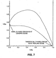
- the remaining two axes in this coordinate system are used to specify the shape of a stack section in a cross section plane as indicated in Figure 7 with the X axis being in the axial direction extending parallel to the engine centerline and with the Y axis being in the tangential direction that is tangential to the ring platform and parallel to a direction of blade rotation at a point.
- the radially stacked sections so specified are to be smoothly joined together in providing a complete surface for a blade 10.
- the inner diameter 14 surface of the flow passageway between the blades is also contoured as specified here and smoothly joined with each corresponding one of blades 10.
- the axial chord of a blade or airfoil is the axial distance between the leading and trailing edges thereof.
- the pitch is the tangential distance between adjacent blades or airfoils mounted on the platform ring.
- the root, or inner diameter (ID) section of the blade or airfoil is the section thereof closest to the engine centerline, and the tip, or outer diameter (OD) section is the section thereof farthest form the engine centerline.
- the root radius is the radial distance from the engine centerline to the root section.
- normalization parameters used in normalization equations given below for use in converting normalized blade or airfoil surface coordinates for sections of the blade given in the tables below to absolute blade or airfoil coordinates to selectively scale such blades to the various sizes suited for various sized corresponding turbine engines.
- the blade root axial chord normalization parameter represented as Bx root has a normalization parameter value of 1.155630 in.
- the blade span (form the ID section to the OD section) represented as h, as above, has a normalization parameter value of 1.905000 in.
- the blade root pitch represented as Pitch root has a normalization parameter value of 1.081550 in., as determined through the platform ring radius and the number of blades selected to be mounted thereon, and the blade root radius represented as R root has a normalization parameter value of 10.328000 in.
- Airfoil Surface tabulates the normalized section cold, uncoated airfoil surface coordinates for the 16 airfoil sections indicated in Figure 6 that describe the three dimensional shape of blade or airfoil 10 with a surface profile tolerance of ⁇ 0.0500 in. including coating and manufacturing variability.
- Each of these sections is normalized by its own axial chord (Bx). The coordinates are arranged such that they start at the leading edge, traverse clockwise around the airfoil on the convex surface to the trailing edge, and then continue on the concave surface of the section back to the leading edge.
- the span fraction z/h ranges from the root section of 0.0 to the tip (or outer diameter) section of 1.0.
- Figure 8 shows a plurality of blade cross section views from the Table 1 defined sections 1, 4, 6, 9 and 16.
- Table 2 Axial Chord Distribution, tabulates the variation in the radial direction of the axial chord of each of the cold, uncoated blade sections shown in Figure 6.
- the airfoil sections each have a unique axial chord, and this chord is used in normalizing the airfoil section coordinates.
- the local axial chord has been normalized by the root axial chord. So, for example, the tip section has an axial chord that is only 65.9% of the length of the root section (typical of a turbine blade).
- Table 2 Axial Chord Distribution Radial Span Fraction Bx/BxRoot 0.000000 1.000000 0.053543 0.977986 0.142782 0.945969 0.249869 0.915206 0.375013 0.887715 0.499738 0.859176 0.624987 0.819432 0.688714 0.794787 0.750131 0.768499 0.796325 0.747809 0.835696 0.730424 0.875066 0.714121 0.911690 0.698649 0.941207 0.685704 0.970604 0.671988 1.000000 0.659138
- Table 3 Radial Stacking Distribution, tabulates the offsets for cold, uncoated blades required to accurately stack the blade airfoil sections of Figure 6 relative to one another in accord with the sections as dimensioned in the foregoing.
- the leading edge points are not all lined up along a radial line, there is some axial sweep and tangential lean to the three dimensional blade shape.
- a radial distribution of axial and tangential offsets is supplied, all relative to the root section. The offsets are normalized by the root axial chord in the axial direction and by the root pitch in the tangential direction.
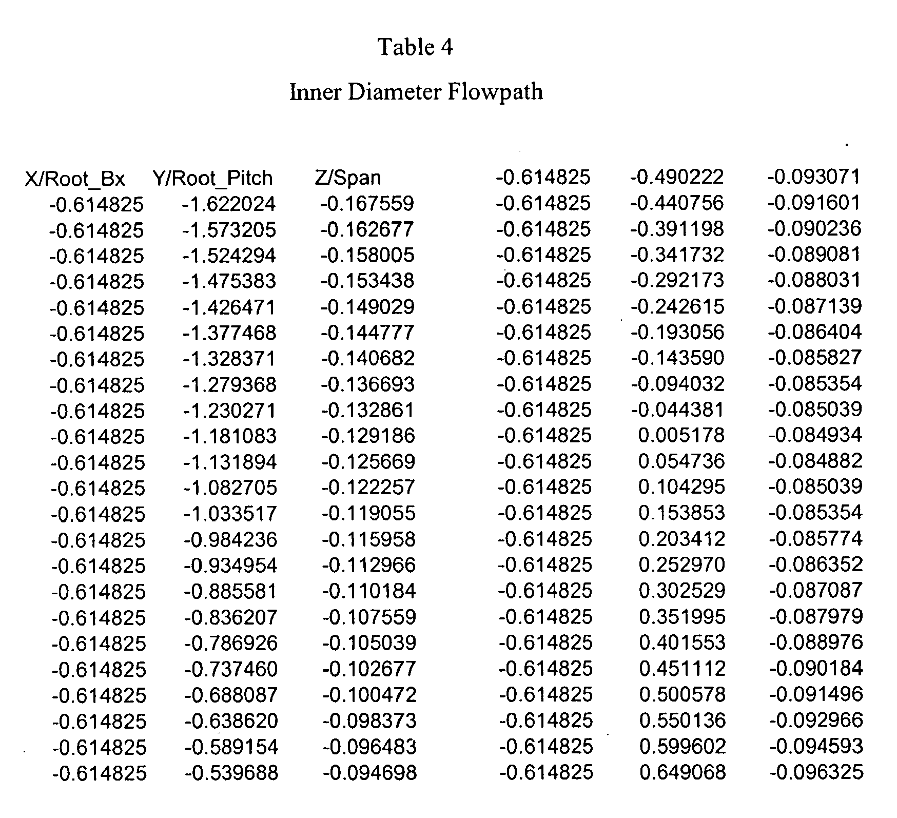
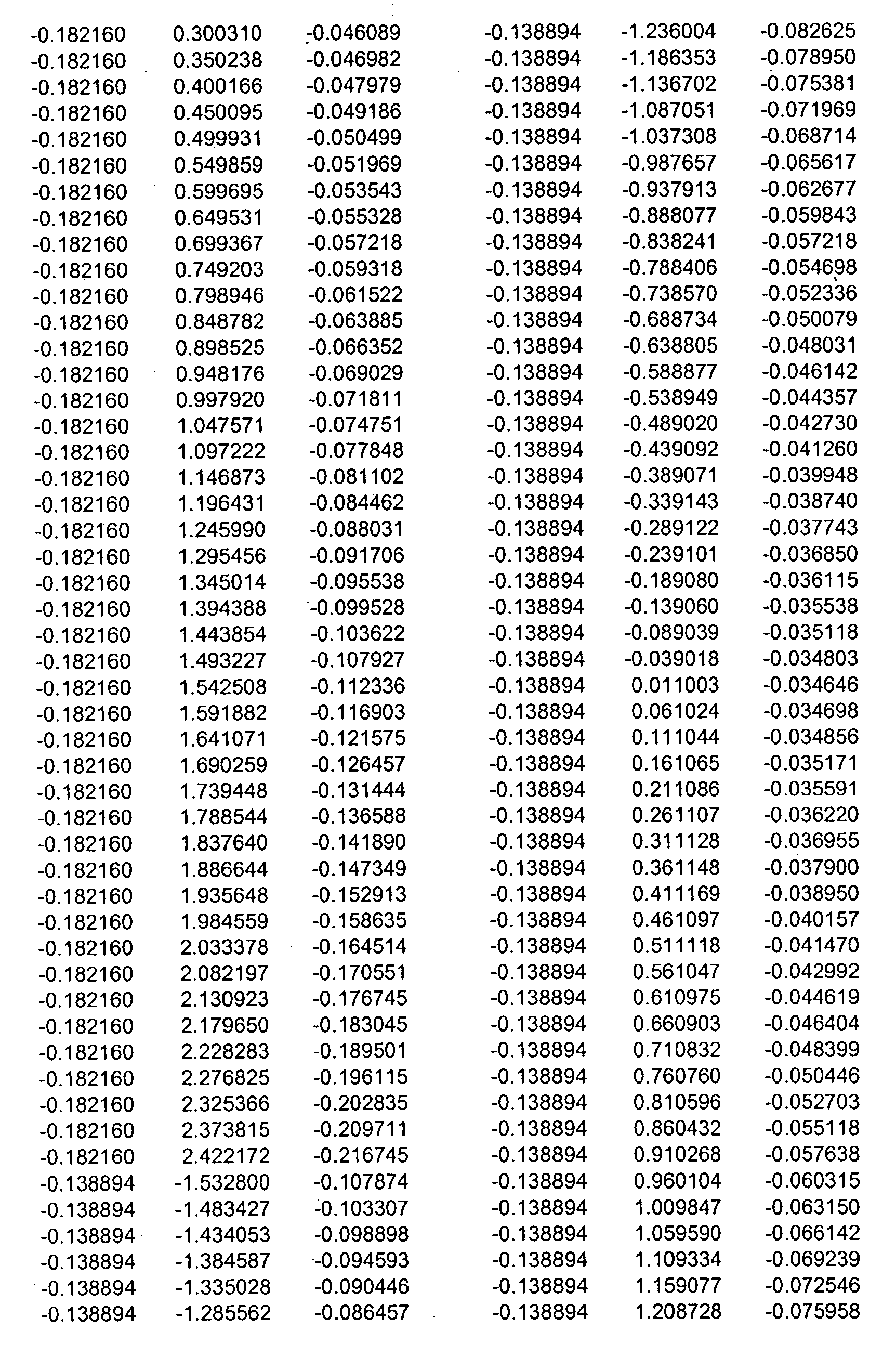
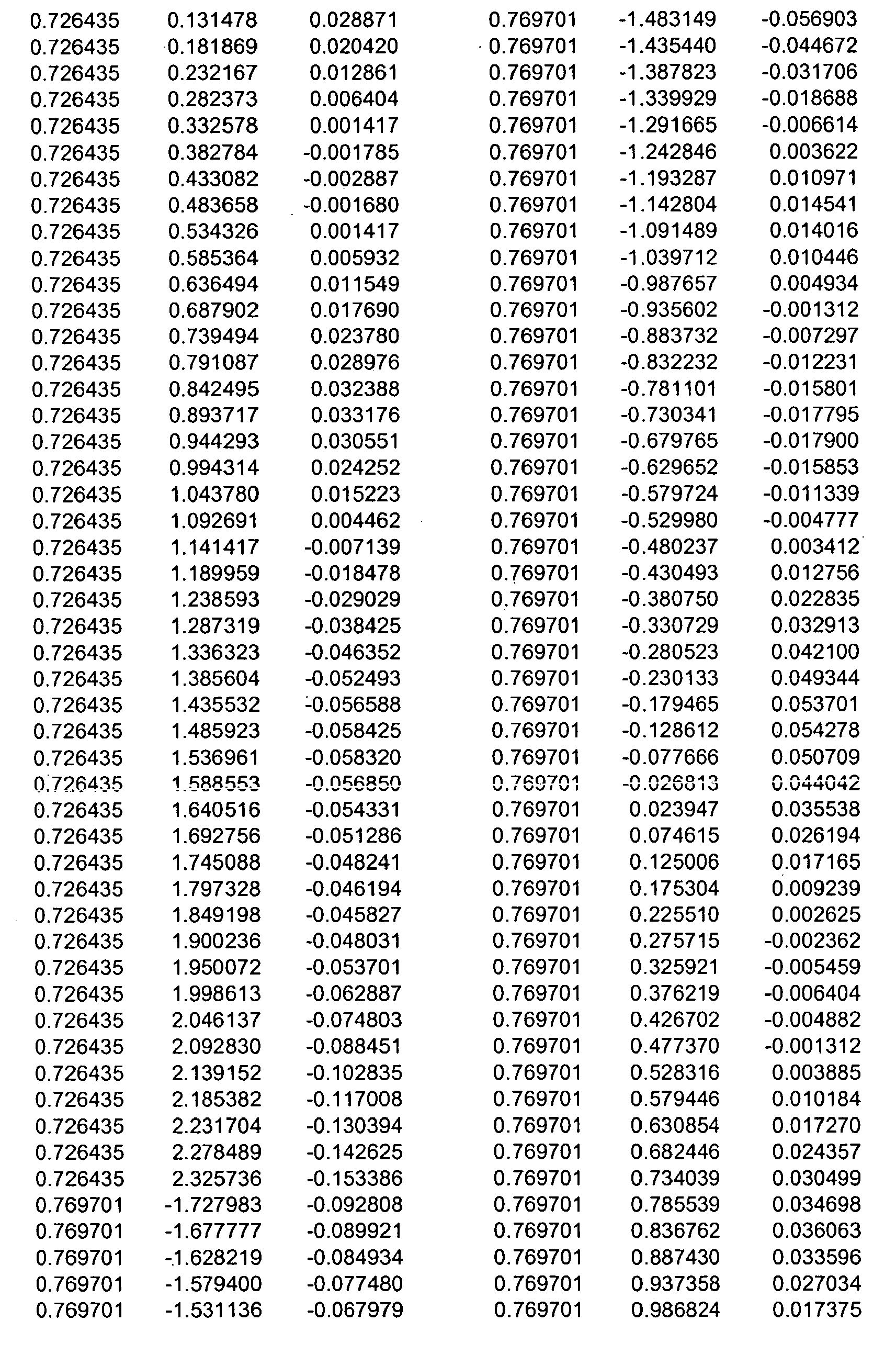
- Table 4 Inner Diameter Flowpath, tabulates the normalized coordinates of the cold, uncoated ring platform surface forming the inner diameter passageway limit described above with a surface profile tolerance of ⁇ 0.0500 in. including coating and manufacturing variability.
- the ring platform surface, or flowpath is a three dimensional shape that begins upstream of the root section leading edge and concludes downstream of the root section trailing edge.
- the flowpath varies in radius from the engine centerline with both axial and tangential position, and so the coordinates describe a surface rather than a line.
- the axial coordinate is normalized by the root axial chord
- the tangential coordinate is normalized by the root pitch
- the radial coordinate is normalized by the airfoil span.
- the origin (0,0,0) of the surface is aligned with the root section leading edge.
- the surface platform surface dips below the root section radius in some places which leads to negative radial values in the table for those locations.
- the normalized coordinates for any of the sections of blade 10 shown in Figure 6, and for the ring platform surface 14, set out in the foregoing tables can be converted to the coordinates for a selected blade size and platform surface in absolute dimension space using the normalization equations given below.
- y absolute y local Bx local ) ( Bx local Bx root ⁇ Bx root + yOffset local Pitch root ( Pitch root ) where yOffset local /Pitch root is obtained from the Radial Stacking Distribution from Table 3.
- R absolute SpanFraction ⁇ h + R root where h is the airfoil span, and R root is the reference root section radius relative to the engine centerline.
- the entire airfoil can then be shifted to any other location in space.
- the airfoil geometry includes tolerances due to manufacturing, surface finish and coating variability of about ⁇ 0.0500 in.
- the airfoil as described can be rotated about its radial axis ⁇ 20° depending on the particular turbine application.
Landscapes
- Engineering & Computer Science (AREA)
- Physics & Mathematics (AREA)
- Fluid Mechanics (AREA)
- Mechanical Engineering (AREA)
- General Engineering & Computer Science (AREA)
- Turbine Rotor Nozzle Sealing (AREA)
- Enzymes And Modification Thereof (AREA)
- Apparatus Associated With Microorganisms And Enzymes (AREA)
Abstract
Description
- The present invention relates to turbine blades for turbomachinery such as gas turbine engines and, more particularly, to improved geometrical shapes for such blades and the platform from which they extend.
- Turbine blades are mounted circumferentially on an inner diameter platform about a turbine shaft to allow rotation thereof in streams of working medium fluids to extract energy and work therefrom as those fluids flow around and past such blades through the flow passages between them. Such flows can be transonic in accelerating from below the speed of sound coming into the blade region to being above the speed of sound in the exit region. In these situations inefficiencies due to shock wave losses are important.
- Blade airfoil surface profiles, and the geometry of the airfoil and the platform on which the blade is mounted become very important in achieving high efficiencies. In addition, a blade design to be suitable must minimize the penalties imposed on the engine system by the weight and cost of the blades, and need for cooling air therein, a goal sought through reducing the number of blades provided about the platform circumference for each blade stage used. However, the remaining blades must then extract more work, the lift or loading of the blade, from the fluid streams passing thereby which tends to reduce blade efficiency. A high lift blade will have a Zweifel lift coefficient (the ratio of the actual load to the ideal load) that is greater than 1.1. Thus, there is a desire for a blade that achieves high efficiency during transonic operation while having a large lift loading.
- The present invention provides a turbine blade system including a blade airfoil having an airfoil shape with the blade airfoil having a nominal profile substantially in accordance with normalized Cartesian coordinate values of X, Y and Z set forth in Table 1 below and which values are dimensionless values that are convertible to corresponding absolute distance values through manipulating them in accord with corresponding normalization equations. The X and Y absolute distance values, when connected by smooth continuing arcs, define nominal airfoil profile sections at each Z absolute distance value, and these nominal airfoil profile sections, when joined smoothly with adjacent ones thereof, form a complete nominal airfoil shape that is substantially matched by the airfoil shape of the blade airfoil. This blade airfoil can be supported on a ring platform having a support surface with a support surface shape in the vicinity of the location at which that blade airfoil is supported thereon such that the support surface smoothly joins with the airfoil shape of that blade airfoil, the support surface having a nominal profile substantially in accordance with normalized Cartesian coordinate values of X, Y and Z set forth in Table 4 below and which values are dimensionless values that are convertible to corresponding absolute distance values through manipulating them in accord with corresponding normalization equations, and wherein X and Y absolute distance values at various Z absolute distance values, when connected by smooth continuing arcs, form a nominal support surface shape substantially matched by the support surface shape of the support surface.
-
- Figure 1 provides a diagrammatic side view of a blade mounted on a rotatable platform adjacent a fluid guide vane,
- Figure 2 shows a pictorial perspective view of the turbine blade embodying the present invention,
- Figure 3 shows a side pictorial view of a platform ring stage having blades like that of Figure 2 mounted thereon as an embodiment of the present invention,
- Figure 4 shows a diagrammatic top view of a portion of Figure 3 marked with certain variables,
- Figure 5 shows a perspective diagram of the blade of Figure 2 that is shown with corresponding three-dimensional coordinate axes,
- Figure 6 shows a diagrammatic side view of the blade of Figure 2 marked with a plurality of sectioning lines arrayed along with a corresponding one of the coordinate dimensional axis from Figure 5,
- Figure 7 shows a typical blade cross section view of the blade of Figure 2 for a section of that blade designated in Figure 6 that is shown with two of the corresponding two dimensional coordinates axes from Figure 5, and
- Figure 8 shows a plurality of blade cross section views of the blade of Figure 2 for sections of that blade designated in Figure 6 as the sections selected ascend from the blade mounting platform.
- Figure 1 shows the relationship of a blade, 10, mounted on a rotatable platform extending about an unseen turbine shaft adjacent a fluid guide vane, 11. Above them is shown the edge of the engine wall limiting the outer extent of the fluid flow path past
blade 10 andvane 11, that is, forming the outer diameter, of this fluid flowpassage containing blade 10 andvane 11.Rotatable blade 10 has a gap, 13, between the tip of that blade andouter diameter 12 butvane 11 is fixed to the structure providing this fluid flow passageway outer diameter as well as to the structure supporting it from below. That vane supporting structure and the platform on whichblade 10 is mounted together limit the inner extent of the fluid flow path pastblade 10 andvane 11, that is, forming the inner diameter, 12, of this fluid flowpassage containing blade 10 andvane 11.Blade 10 is shown having an outward extent from the platform on which it is mounted to its tip designated as its span, 15. -
Blade 10 and theinner diameter 12 surface of the platform on whichblade 10 is mounted of the present invention are shown in the pictorial perspective view of Figure 2, and a plurality ofblades 10 so mounted are shown in Figure 3 circumferentially positioned about the rotatable ring platform supporting them on which theinner diameter surface 14 of the fluid passageway is indicated. Sixty such blades are so provided on the ring platform example shown in Figure 3. In addition to what is shown in Figures 2 and 3,blades 10 can be positioned through being selectively rotated about a radial axis extending outward from the engine centerline from what is shown by up to about ± 10°. - Figure 4 shows a diagrammatic top view of a portion of the platform ring in Figure 3 with certain variables marked thereon used in calculating the Zweifel lift coefficient for
blades 10. The Zweifel lift coefficient is defined as the ratio of the actual load and the ideal load, and is given by:
where: - g = acceleration due to gravity of 32.2 ft/s2
- ṁ= mass flow (lbm/s)
- ΔCu = Cu2 - Cu1 = change in tangential velocity across the blade (ft/s)
- ρ = density (lbm-s2/ft4)
- W2 = exit relative velocity (ft/s)
- bx = axial chord (ft)
- h = span (ft)
- A perspective diagram of the blade of Figure 2 is shown in Figure 5 with the three dimensional coordinates, X, Y and Z, of a Cartesian coordinate system shown that will be used in providing a description of the geometry of the blade, and surface of the platform supporting that blade, that is, a description of the shapes involved. The shape of
blade 10 of the present invention can be specified using an outwardly stacked, or radially stacked, series of cross section portions of that blade, stacked along itsspan 15 extending outward from the ring center as indicated in Figure 6, with the radial axis extending perpendicular to the engine centerline (and so the platform ring centerline) being designated the Z axis shown in Figure 5. The remaining two axes in this coordinate system, the X and the Y axes, are used to specify the shape of a stack section in a cross section plane as indicated in Figure 7 with the X axis being in the axial direction extending parallel to the engine centerline and with the Y axis being in the tangential direction that is tangential to the ring platform and parallel to a direction of blade rotation at a point. The radially stacked sections so specified are to be smoothly joined together in providing a complete surface for ablade 10. Theinner diameter 14 surface of the flow passageway between the blades is also contoured as specified here and smoothly joined with each corresponding one ofblades 10. - Some definitions of terms used in the description include the leading edge as blade or airfoil point farthest toward the forward direction of the engine and the trailing edge as blade or airfoil point farthest toward the rearward from the forward direction of the engine. The axial chord of a blade or airfoil is the axial distance between the leading and trailing edges thereof. The pitch is the tangential distance between adjacent blades or airfoils mounted on the platform ring. The root, or inner diameter (ID) section of the blade or airfoil is the section thereof closest to the engine centerline, and the tip, or outer diameter (OD) section is the section thereof farthest form the engine centerline. The root radius is the radial distance from the engine centerline to the root section.
- In addition, there are some normalization parameters used in normalization equations given below for use in converting normalized blade or airfoil surface coordinates for sections of the blade given in the tables below to absolute blade or airfoil coordinates to selectively scale such blades to the various sizes suited for various sized corresponding turbine engines. The blade root axial chord normalization parameter represented as Bxroot has a normalization parameter value of 1.155630 in. The blade span (form the ID section to the OD section) represented as h, as above, has a normalization parameter value of 1.905000 in. The blade root pitch represented as Pitchroot has a normalization parameter value of 1.081550 in., as determined through the platform ring radius and the number of blades selected to be mounted thereon, and the blade root radius represented as Rroot has a normalization parameter value of 10.328000 in.
- Table 1, Airfoil Surface (Normalized), tabulates the normalized section cold, uncoated airfoil surface coordinates for the 16 airfoil sections indicated in Figure 6 that describe the three dimensional shape of blade or
airfoil 10 with a surface profile tolerance of ± 0.0500 in. including coating and manufacturing variability. Each of these sections is normalized by its own axial chord (Bx). The coordinates are arranged such that they start at the leading edge, traverse clockwise around the airfoil on the convex surface to the trailing edge, and then continue on the concave surface of the section back to the leading edge. The span fraction z/h ranges from the root section of 0.0 to the tip (or outer diameter) section of 1.0. These coordinates can be translated to absolute coordinates using the root axial chord (BXroot) along with the values in Table 2, Axial Chord Distribution, and Table 3, Radial Stacking Distribution, set out below. Figure 8 shows a plurality of blade cross section views from the Table 1 definedsections 


- Table 2, Axial Chord Distribution, tabulates the variation in the radial direction of the axial chord of each of the cold, uncoated blade sections shown in Figure 6. The airfoil sections each have a unique axial chord, and this chord is used in normalizing the airfoil section coordinates. For simplicity the local axial chord has been normalized by the root axial chord. So, for example, the tip section has an axial chord that is only 65.9% of the length of the root section (typical of a turbine blade).
Table 2 Axial Chord Distribution Radial Span Fraction Bx/BxRoot 0.000000 1.000000 0.053543 0.977986 0.142782 0.945969 0.249869 0.915206 0.375013 0.887715 0.499738 0.859176 0.624987 0.819432 0.688714 0.794787 0.750131 0.768499 0.796325 0.747809 0.835696 0.730424 0.875066 0.714121 0.911690 0.698649 0.941207 0.685704 0.970604 0.671988 1.000000 0.659138 - Table 3, Radial Stacking Distribution, tabulates the offsets for cold, uncoated blades required to accurately stack the blade airfoil sections of Figure 6 relative to one another in accord with the sections as dimensioned in the foregoing. For example, the leading edge points are not all lined up along a radial line, there is some axial sweep and tangential lean to the three dimensional blade shape. A radial distribution of axial and tangential offsets is supplied, all relative to the root section. The offsets are normalized by the root axial chord in the axial direction and by the root pitch in the tangential direction.
Table 3 Radial Stacking Distribution Radial Span Fraction Axial Offset (Normalized by Root Bx) of LE Point Relative to Root LE Tangential Offset (Normalized By Root Pitch) of LE Point Relative to Root LE 0.000000 0.00000 0.00000 0.053543 0.02198 -0.01591 0.142782 0.05290 -0.03948 0.249869 0.08066 -0.06302 0.375013 0.10232 -0.08381 0.499738 0.12246 -0.09666 0.624987 0.14962 -0.09909 0.688714 0.16394 -0.09320 0.750131 0.17619 -0.08087 0.796325 0.18304 -0.06628 0.835696 0.18646 -0.04983 0.875066 0.18695 -0.02916 0.911690 0.18632 -0.00568 0.941207 0.18587 0.01662 0.970604 0.18551 0.04186 1.000000 0.18491 0.07030 - Table 4, Inner Diameter Flowpath, tabulates the normalized coordinates of the cold, uncoated ring platform surface forming the inner diameter passageway limit described above with a surface profile tolerance of ± 0.0500 in. including coating and manufacturing variability. The ring platform surface, or flowpath, is a three dimensional shape that begins upstream of the root section leading edge and concludes downstream of the root section trailing edge. The flowpath varies in radius from the engine centerline with both axial and tangential position, and so the coordinates describe a surface rather than a line. The axial coordinate is normalized by the root axial chord, the tangential coordinate is normalized by the root pitch, and the radial coordinate is normalized by the airfoil span. The origin (0,0,0) of the surface is aligned with the root section leading edge. The surface platform surface dips below the root section radius in some places which leads to negative radial values in the table for those locations.






- The normalized coordinates for any of the sections of
blade 10 shown in Figure 6, and for thering platform surface 14, set out in the foregoing tables can be converted to the coordinates for a selected blade size and platform surface in absolute dimension space using the normalization equations given below. The conversion for use in converting normalized blade or airfoil surface coordinates for sections of the blade to absolute blade or airfoil coordinates are provided by the following equations beginning with the axial coordinates equation
where
xlocal/Bxlocal is the normalized airfoil coordinate from Table 1,
BxlocalBxroot is obtained from the Axial Chord Distribution from Table 2, and
XOffsetlocal/Bxroot is obtained from the Radial Stacking Distribution from Table 3. - Similarly, the tangential coordinates can be found using

where
yOffsetlocal/Pitchroot is obtained from the Radial Stacking Distribution from Table 3. - The absolute radius of any section can be found through

where
h is the airfoil span, and
Rroot is the reference root section radius relative to the engine centerline. - The ring platform surface, or inner diameter flowpath, can also be converted from normalized to absolute coordinates using the following normalization equations


- Once determined in absolute space relative to the root section leading edge, the entire airfoil can then be shifted to any other location in space.
- The airfoil geometry includes tolerances due to manufacturing, surface finish and coating variability of about ± 0.0500 in. In addition, the airfoil as described can be rotated about its radial axis ± 20° depending on the particular turbine application.
- Although the present invention has been described with reference to preferred embodiments, workers skilled in the art will recognize that changes may be made in form and detail without departing from the spirit and scope of the invention.
Claims (11)
- A turbine blade system including a blade airfoil (10) having an airfoil shape, the blade airfoil having a nominal profile substantially in accordance with normalized Cartesian coordinate values of X, Y and Z set forth in Table 1 herein and which values are dimensionless values that are convertible to corresponding absolute distance values through manipulating them in accord with corresponding normalization equations, and wherein X and Y absolute distance values, when connected by smooth continuing arcs, define nominal airfoil profile sections at each Z absolute distance value, and the nominal airfoil profile sections, when joined smoothly with adjacent ones thereof in accord with Tables 2 and 3 herein, form a complete nominal airfoil shape that is substantially matched by the airfoil shape of the blade airfoil.
- The turbine blade system of claim 1 further comprising a platform ring on which the blade airfoil is supported along with a plurality of similar blade airfoils positioned about the circumference of the ring platform.
- The turbine blade system of claim 2 wherein the ring platform has a support surface with a support surface shape in the vicinity of the location at which the blade airfoil is supported thereon with that support surface smoothly joining with the airfoil shape, the support surface having a nominal profile substantially in accordance with normalized Cartesian coordinate values of X, Y and Z set forth in Table 4 herein and which values are dimensionless values that are convertible to corresponding absolute distance values through manipulating them in accord with corresponding normalization equations, and wherein X and Y absolute distance values at various Z absolute distance values, when connected by smooth continuing arcs, form a nominal support surface shape substantially matched by the support surface shape of the support surface.
- The turbine blade system of claim 2 or 3 wherein a corresponding radius of the ring platform extends through each of the blade airfoils and each of the blade airfoils is positioned selectively rotated within ± 10° with respect the radius corresponding thereto from the position set forth therefore in Tables 1 and 4 as converted to absolute distance values.
- The turbine blade system of claim 3 or 4 wherein the support surface has a support surface shape that occurs anywhere in a spatial region about a nominal support surface shape that is bounded by being within ±0.050 inches in directions normal to any locations on the nominal support surface shape.
- The turbine blade system of any preceding claim wherein the normalization equations allow the X, Y and Z absolute distance values to be scaled as a function of selected parameters to thereby provide a nominal airfoil shape that is scaleable over ranges of absolute distance values for providing a selection of alternative sizes for corresponding blade airfoils.
- The turbine blade system of any preceding claim wherein the blade airfoil has an airfoil shape that occurs anywhere in a spatial region about a nominal airfoil shape that is bounded by being within ±0.050 inches in directions normal to any locations on the nominal airfoil shape.
- The turbine blade system of any preceding claim wherein the height of the blade airfoil from root to tip is 1.905000 inches.
- The turbine blade system of any preceding claim wherein the normalization equations depend on the normalization parameters blade root axial chord represented as Bxroot, the blade span (form the ID section to the OD section) represented as h, the blade root pitch represented as Pitchroot, and the blade root radius represented as Rroot.
- A ring platform for a turbine blade system on which a plurality of blade airfoils are supported positioned about the circumference of the ring platform, the ring platform having a support surface with a support surface shape in the vicinity of the location at which a blade airfoil is supported thereon with that support surface smoothly joining with the airfoil shape of that blade airfoil, the support surface having a nominal profile substantially in accordance with normalized Cartesian coordinate values of X, Y and Z set forth in Table 4 and which values are dimensionless values that are convertible to corresponding absolute distance values through manipulating them in accord with corresponding normalization equations, and wherein X and Y absolute distance values at various Z absolute distance values, when connected by smooth continuing arcs, form a nominal support surface shape substantially matched by the support surface shape of the support surface.
- The ring platform of claim 10 wherein the support surface has a support surface shape that occurs anywhere in a spatial region about a nominal support surface shape that is bounded by being within ±0.050 inches in directions normal to any locations on the nominal support surface shape.
Applications Claiming Priority (1)
| Application Number | Priority Date | Filing Date | Title |
|---|---|---|---|
| US11/504,980 US7581930B2 (en) | 2006-08-16 | 2006-08-16 | High lift transonic turbine blade |
Publications (2)
| Publication Number | Publication Date |
|---|---|
| EP1890007A2 true EP1890007A2 (en) | 2008-02-20 |
| EP1890007A3 EP1890007A3 (en) | 2011-02-23 |
Family
ID=38473395
Family Applications (1)
| Application Number | Title | Priority Date | Filing Date |
|---|---|---|---|
| EP07253094A Withdrawn EP1890007A3 (en) | 2006-08-16 | 2007-08-07 | High lift transonic turbine blade |
Country Status (3)
| Country | Link |
|---|---|
| US (1) | US7581930B2 (en) |
| EP (1) | EP1890007A3 (en) |
| JP (1) | JP5154165B2 (en) |
Cited By (2)
| Publication number | Priority date | Publication date | Assignee | Title |
|---|---|---|---|---|
| EP2428644A1 (en) * | 2010-09-08 | 2012-03-14 | United Technologies Corporation | Turbine vane airfoil |
| EP2428643A1 (en) * | 2010-09-08 | 2012-03-14 | United Technologies Corporation | Turbine blade airfoil |
Families Citing this family (30)
| Publication number | Priority date | Publication date | Assignee | Title |
|---|---|---|---|---|
| KR101160991B1 (en) | 2006-02-10 | 2012-06-29 | 한국델파이주식회사 | Cooling Fan for Auto Mobile |
| US20110006165A1 (en) * | 2009-07-10 | 2011-01-13 | Peter Ireland | Application of conformal sub boundary layer vortex generators to a foil or aero/ hydrodynamic surface |
| US8360731B2 (en) * | 2009-12-04 | 2013-01-29 | United Technologies Corporation | Tip vortex control |
| US8356975B2 (en) * | 2010-03-23 | 2013-01-22 | United Technologies Corporation | Gas turbine engine with non-axisymmetric surface contoured vane platform |
| US9976433B2 (en) | 2010-04-02 | 2018-05-22 | United Technologies Corporation | Gas turbine engine with non-axisymmetric surface contoured rotor blade platform |
| US8596986B2 (en) * | 2011-02-23 | 2013-12-03 | Alstom Technology Ltd. | Unflared compressor blade |
| DE102011120682A1 (en) * | 2011-12-08 | 2013-06-13 | Rolls-Royce Deutschland Ltd & Co Kg | Method for selecting a blade geometry |
| US20130156602A1 (en) † | 2011-12-16 | 2013-06-20 | United Technologies Corporation | Film cooled turbine component |
| US9133713B2 (en) | 2012-07-02 | 2015-09-15 | United Technologies Corporation | Gas turbine engine turbine blade airfoil profile |
| US9115588B2 (en) | 2012-07-02 | 2015-08-25 | United Technologies Corporation | Gas turbine engine turbine blade airfoil profile |
| US9957801B2 (en) | 2012-08-03 | 2018-05-01 | United Technologies Corporation | Airfoil design having localized suction side curvatures |
| US8979499B2 (en) | 2012-08-17 | 2015-03-17 | United Technologies Corporation | Gas turbine engine airfoil profile |
| US8997494B2 (en) * | 2012-09-28 | 2015-04-07 | United Technologies Corporation | Gas turbine engine fan blade airfoil profile |
| EP2964932B1 (en) | 2013-03-04 | 2020-11-04 | United Technologies Corporation | Airfoil and corresponding gas turbine engine |
| WO2015112222A2 (en) | 2013-11-04 | 2015-07-30 | United Technologies Corporation | Gas turbine engine airfoil profile |
| US20170130587A1 (en) * | 2015-11-09 | 2017-05-11 | General Electric Company | Last stage airfoil design for optimal diffuser performance |
| US10677066B2 (en) | 2015-11-23 | 2020-06-09 | United Technologies Corporation | Turbine blade with airfoil tip vortex control |
| US20170145827A1 (en) * | 2015-11-23 | 2017-05-25 | United Technologies Corporation | Turbine blade with airfoil tip vortex control |
| US10480323B2 (en) | 2016-01-12 | 2019-11-19 | United Technologies Corporation | Gas turbine engine turbine blade airfoil profile |
| US10443392B2 (en) * | 2016-07-13 | 2019-10-15 | Safran Aircraft Engines | Optimized aerodynamic profile for a turbine vane, in particular for a nozzle of the second stage of a turbine |
| US10443393B2 (en) * | 2016-07-13 | 2019-10-15 | Safran Aircraft Engines | Optimized aerodynamic profile for a turbine vane, in particular for a nozzle of the seventh stage of a turbine |
| US11286787B2 (en) | 2016-09-15 | 2022-03-29 | Raytheon Technologies Corporation | Gas turbine engine airfoil with showerhead cooling holes near leading edge |
| US10370976B2 (en) | 2017-08-17 | 2019-08-06 | United Technologies Corporation | Directional cooling arrangement for airfoils |
| US10570748B2 (en) | 2018-01-10 | 2020-02-25 | United Technologies Corporation | Impingement cooling arrangement for airfoils |
| US11105206B1 (en) * | 2019-07-26 | 2021-08-31 | Raytheon Technologies Corporation | Turbine airfoil |
| US11118460B1 (en) * | 2020-03-20 | 2021-09-14 | General Electric Company | Turbine rotor blade airfoil profile |
| US11286779B2 (en) * | 2020-06-03 | 2022-03-29 | Honeywell International Inc. | Characteristic distribution for rotor blade of booster rotor |
| IT202100000296A1 (en) | 2021-01-08 | 2022-07-08 | Gen Electric | TURBINE ENGINE WITH VANE HAVING A SET OF DIMPLES |
| DE102022109455A1 (en) | 2022-04-19 | 2023-10-19 | MTU Aero Engines AG | GUIDE AND BLADE RING FOR A MANUAL ENGINE |
| CN119467022B (en) * | 2024-11-12 | 2025-09-19 | 西北工业大学 | A turbine flow regulation method based on small flaps |
Citations (1)
| Publication number | Priority date | Publication date | Assignee | Title |
|---|---|---|---|---|
| EP0937862A2 (en) * | 1998-02-20 | 1999-08-25 | BMW Rolls-Royce GmbH | Blade form for axial turbines |
Family Cites Families (86)
| Publication number | Priority date | Publication date | Assignee | Title |
|---|---|---|---|---|
| US5525038A (en) * | 1994-11-04 | 1996-06-11 | United Technologies Corporation | Rotor airfoils to control tip leakage flows |
| JPH09193295A (en) * | 1996-01-22 | 1997-07-29 | Senshin Zairyo Riyou Gas Jienereeta Kenkyusho:Kk | Ring or bling of fiber reinforced metal composite and method for producing the same |
| US5980209A (en) * | 1997-06-27 | 1999-11-09 | General Electric Co. | Turbine blade with enhanced cooling and profile optimization |
| CN1246570C (en) * | 1999-10-15 | 2006-03-22 | 株式会社日立制作所 | Turbine rotor vane |
| US6358012B1 (en) * | 2000-05-01 | 2002-03-19 | United Technologies Corporation | High efficiency turbomachinery blade |
| US6461110B1 (en) * | 2001-07-11 | 2002-10-08 | General Electric Company | First-stage high pressure turbine bucket airfoil |
| US6398489B1 (en) * | 2001-02-08 | 2002-06-04 | General Electric Company | Airfoil shape for a turbine nozzle |
| US6474948B1 (en) * | 2001-06-22 | 2002-11-05 | General Electric Company | Third-stage turbine bucket airfoil |
| US6450770B1 (en) * | 2001-06-28 | 2002-09-17 | General Electric Company | Second-stage turbine bucket airfoil |
| US6503059B1 (en) * | 2001-07-06 | 2003-01-07 | General Electric Company | Fourth-stage turbine bucket airfoil |
| US6503054B1 (en) * | 2001-07-13 | 2003-01-07 | General Electric Company | Second-stage turbine nozzle airfoil |
| US6461109B1 (en) * | 2001-07-13 | 2002-10-08 | General Electric Company | Third-stage turbine nozzle airfoil |
| US6558122B1 (en) * | 2001-11-14 | 2003-05-06 | General Electric Company | Second-stage turbine bucket airfoil |
| US6669445B2 (en) | 2002-03-07 | 2003-12-30 | United Technologies Corporation | Endwall shape for use in turbomachinery |
| US6685434B1 (en) * | 2002-09-17 | 2004-02-03 | General Electric Company | Second stage turbine bucket airfoil |
| US6715990B1 (en) * | 2002-09-19 | 2004-04-06 | General Electric Company | First stage turbine bucket airfoil |
| US6722852B1 (en) * | 2002-11-22 | 2004-04-20 | General Electric Company | Third stage turbine bucket airfoil |
| US6722853B1 (en) * | 2002-11-22 | 2004-04-20 | General Electric Company | Airfoil shape for a turbine nozzle |
| US6779977B2 (en) * | 2002-12-17 | 2004-08-24 | General Electric Company | Airfoil shape for a turbine bucket |
| US6887041B2 (en) * | 2003-03-03 | 2005-05-03 | General Electric Company | Airfoil shape for a turbine nozzle |
| US6779980B1 (en) * | 2003-03-13 | 2004-08-24 | General Electric Company | Airfoil shape for a turbine bucket |
| US6739838B1 (en) * | 2003-03-17 | 2004-05-25 | General Electric Company | Airfoil shape for a turbine bucket |
| US6739839B1 (en) * | 2003-03-31 | 2004-05-25 | General Electric Company | First-stage high pressure turbine bucket airfoil |
| US6832897B2 (en) * | 2003-05-07 | 2004-12-21 | General Electric Company | Second stage turbine bucket airfoil |
| US6769878B1 (en) * | 2003-05-09 | 2004-08-03 | Power Systems Mfg. Llc | Turbine blade airfoil |
| US6736599B1 (en) * | 2003-05-14 | 2004-05-18 | General Electric Company | First stage turbine nozzle airfoil |
| US6854961B2 (en) * | 2003-05-29 | 2005-02-15 | General Electric Company | Airfoil shape for a turbine bucket |
| US6808368B1 (en) * | 2003-06-13 | 2004-10-26 | General Electric Company | Airfoil shape for a turbine bucket |
| US6769879B1 (en) * | 2003-07-11 | 2004-08-03 | General Electric Company | Airfoil shape for a turbine bucket |
| US6884038B2 (en) * | 2003-07-18 | 2005-04-26 | General Electric Company | Airfoil shape for a turbine bucket |
| US6910868B2 (en) * | 2003-07-23 | 2005-06-28 | General Electric Company | Airfoil shape for a turbine bucket |
| US6866477B2 (en) * | 2003-07-31 | 2005-03-15 | General Electric Company | Airfoil shape for a turbine nozzle |
| US6857855B1 (en) * | 2003-08-04 | 2005-02-22 | General Electric Company | Airfoil shape for a turbine bucket |
| US6881038B1 (en) * | 2003-10-09 | 2005-04-19 | General Electric Company | Airfoil shape for a turbine bucket |
| US6932577B2 (en) * | 2003-11-21 | 2005-08-23 | Power Systems Mfg., Llc | Turbine blade airfoil having improved creep capability |
| US7001147B1 (en) * | 2004-07-28 | 2006-02-21 | General Electric Company | Airfoil shape and sidewall flowpath surfaces for a turbine nozzle |
| US7094034B2 (en) * | 2004-07-30 | 2006-08-22 | United Technologies Corporation | Airfoil profile with optimized aerodynamic shape |
| US7186090B2 (en) * | 2004-08-05 | 2007-03-06 | General Electric Company | Air foil shape for a compressor blade |
| US7690890B2 (en) * | 2004-09-24 | 2010-04-06 | Ishikawajima-Harima Heavy Industries Co. Ltd. | Wall configuration of axial-flow machine, and gas turbine engine |
| US7384243B2 (en) * | 2005-08-30 | 2008-06-10 | General Electric Company | Stator vane profile optimization |
| CA2633319C (en) * | 2005-12-29 | 2013-02-19 | Rolls-Royce Power Engineering Plc | First stage turbine airfoil |
| US7722329B2 (en) * | 2005-12-29 | 2010-05-25 | Rolls-Royce Power Engineering Plc | Airfoil for a third stage nozzle guide vane |
| US7648334B2 (en) * | 2005-12-29 | 2010-01-19 | Rolls-Royce Power Engineering Plc | Airfoil for a second stage nozzle guide vane |
| CA2634738C (en) * | 2005-12-29 | 2013-03-26 | Rolls-Royce Power Engineering Plc | Second stage turbine airfoil |
| US7632072B2 (en) * | 2005-12-29 | 2009-12-15 | Rolls-Royce Power Engineering Plc | Third stage turbine airfoil |
| WO2007085912A2 (en) * | 2005-12-29 | 2007-08-02 | Rolls-Royce Power Engineering Plc | Airfoil for a first stage nozzle guide vane |
| US7329092B2 (en) * | 2006-01-27 | 2008-02-12 | General Electric Company | Stator blade airfoil profile for a compressor |
| US7329093B2 (en) * | 2006-01-27 | 2008-02-12 | General Electric Company | Nozzle blade airfoil profile for a turbine |
| ITMI20060340A1 (en) * | 2006-02-27 | 2007-08-28 | Nuovo Pignone Spa | SHOVEL OF A ROTOR OF A SECOND STAGE OF A COMPRESSOR |
| US7351038B2 (en) * | 2006-03-02 | 2008-04-01 | Pratt & Whitney Canada Corp. | HP turbine vane airfoil profile |
| US7367779B2 (en) * | 2006-03-02 | 2008-05-06 | Pratt & Whitney Canada Corp. | LP turbine vane airfoil profile |
| US7402026B2 (en) * | 2006-03-02 | 2008-07-22 | Pratt & Whitney Canada Corp. | Turbine exhaust strut airfoil profile |
| US7306436B2 (en) * | 2006-03-02 | 2007-12-11 | Pratt & Whitney Canada Corp. | HP turbine blade airfoil profile |
| US7354249B2 (en) * | 2006-03-02 | 2008-04-08 | Pratt & Whitney Canada Corp. | LP turbine blade airfoil profile |
| US7396211B2 (en) * | 2006-03-30 | 2008-07-08 | General Electric Company | Stator blade airfoil profile for a compressor |
| US7467926B2 (en) * | 2006-06-09 | 2008-12-23 | General Electric Company | Stator blade airfoil profile for a compressor |
| US7537433B2 (en) * | 2006-09-05 | 2009-05-26 | Pratt & Whitney Canada Corp. | LP turbine blade airfoil profile |
| US7625183B2 (en) * | 2006-09-05 | 2009-12-01 | Pratt & Whitney Canada Corp. | LP turbine van airfoil profile |
| US7625182B2 (en) * | 2006-09-05 | 2009-12-01 | Pratt & Whitney Canada Corp. | Turbine exhaust strut airfoil and gas path profile |
| US7537432B2 (en) * | 2006-09-05 | 2009-05-26 | Pratt & Whitney Canada Corp. | HP turbine vane airfoil profile |
| US7534091B2 (en) * | 2006-09-05 | 2009-05-19 | Pratt & Whitney Canada Corp. | HP turbine blade airfoil profile |
| US7611326B2 (en) * | 2006-09-06 | 2009-11-03 | Pratt & Whitney Canada Corp. | HP turbine vane airfoil profile |
| US7520726B2 (en) * | 2006-09-07 | 2009-04-21 | Pratt & Whitney Canada Corp. | HP turbine blade airfoil profile |
| US7520727B2 (en) * | 2006-09-07 | 2009-04-21 | Pratt & Whitney Canada Corp. | HP turbine blade airfoil profile |
| US7520728B2 (en) * | 2006-09-07 | 2009-04-21 | Pratt & Whitney Canada Corp. | HP turbine vane airfoil profile |
| US7572104B2 (en) * | 2006-10-25 | 2009-08-11 | General Electric Company | Airfoil shape for a compressor |
| US7517188B2 (en) * | 2006-10-25 | 2009-04-14 | General Electric Company | Airfoil shape for a compressor |
| US7530793B2 (en) * | 2006-10-25 | 2009-05-12 | General Electric Company | Airfoil shape for a compressor |
| US7510378B2 (en) * | 2006-10-25 | 2009-03-31 | General Electric Company | Airfoil shape for a compressor |
| US7494323B2 (en) * | 2006-10-25 | 2009-02-24 | General Electric Company | Airfoil shape for a compressor |
| US7534094B2 (en) * | 2006-10-25 | 2009-05-19 | General Electric Company | Airfoil shape for a compressor |
| US7517190B2 (en) * | 2006-10-25 | 2009-04-14 | General Electric Company | Airfoil shape for a compressor |
| US7534093B2 (en) * | 2006-10-25 | 2009-05-19 | General Electric Company | Airfoil shape for a compressor |
| US7517196B2 (en) * | 2006-10-25 | 2009-04-14 | General Electric Company | Airfoil shape for a compressor |
| US7566202B2 (en) * | 2006-10-25 | 2009-07-28 | General Electric Company | Airfoil shape for a compressor |
| US7494322B2 (en) * | 2006-10-25 | 2009-02-24 | General Electric Company | Airfoil shape for a compressor |
| US7572105B2 (en) * | 2006-10-25 | 2009-08-11 | General Electric Company | Airfoil shape for a compressor |
| US7517197B2 (en) * | 2006-10-25 | 2009-04-14 | General Electric Company | Airfoil shape for a compressor |
| US7520729B2 (en) * | 2006-10-25 | 2009-04-21 | General Electric Company | Airfoil shape for a compressor |
| US7513748B2 (en) * | 2006-10-25 | 2009-04-07 | General Electric Company | Airfoil shape for a compressor |
| US7540715B2 (en) * | 2006-10-25 | 2009-06-02 | General Electric Company | Airfoil shape for a compressor |
| US7513749B2 (en) * | 2006-10-25 | 2009-04-07 | General Electric Company | Airfoil shape for a compressor |
| US7494321B2 (en) * | 2006-10-25 | 2009-02-24 | General Electric Company | Airfoil shape for a compressor |
| US7534092B2 (en) * | 2006-10-25 | 2009-05-19 | General Electric Company | Airfoil shape for a compressor |
| US7497663B2 (en) * | 2006-10-26 | 2009-03-03 | General Electric Company | Rotor blade profile optimization |
| US7527473B2 (en) * | 2006-10-26 | 2009-05-05 | General Electric Company | Airfoil shape for a turbine nozzle |
-
2006
- 2006-08-16 US US11/504,980 patent/US7581930B2/en not_active Expired - Fee Related
-
2007
- 2007-08-07 EP EP07253094A patent/EP1890007A3/en not_active Withdrawn
- 2007-08-13 JP JP2007210706A patent/JP5154165B2/en active Active
Patent Citations (1)
| Publication number | Priority date | Publication date | Assignee | Title |
|---|---|---|---|---|
| EP0937862A2 (en) * | 1998-02-20 | 1999-08-25 | BMW Rolls-Royce GmbH | Blade form for axial turbines |
Cited By (4)
| Publication number | Priority date | Publication date | Assignee | Title |
|---|---|---|---|---|
| EP2428644A1 (en) * | 2010-09-08 | 2012-03-14 | United Technologies Corporation | Turbine vane airfoil |
| EP2428643A1 (en) * | 2010-09-08 | 2012-03-14 | United Technologies Corporation | Turbine blade airfoil |
| US8393870B2 (en) | 2010-09-08 | 2013-03-12 | United Technologies Corporation | Turbine blade airfoil |
| US8602740B2 (en) | 2010-09-08 | 2013-12-10 | United Technologies Corporation | Turbine vane airfoil |
Also Published As
| Publication number | Publication date |
|---|---|
| JP2008045554A (en) | 2008-02-28 |
| EP1890007A3 (en) | 2011-02-23 |
| US20090162204A1 (en) | 2009-06-25 |
| US7581930B2 (en) | 2009-09-01 |
| JP5154165B2 (en) | 2013-02-27 |
Similar Documents
| Publication | Publication Date | Title |
|---|---|---|
| US7581930B2 (en) | High lift transonic turbine blade | |
| US10408072B2 (en) | Turbine nozzle airfoil profile | |
| US8105043B2 (en) | HP turbine blade airfoil profile | |
| US7862303B2 (en) | Compressor turbine vane airfoil profile | |
| US8439645B2 (en) | High pressure turbine blade airfoil profile | |
| US8167568B2 (en) | High pressure turbine blade airfoil profile | |
| US8714930B2 (en) | Airfoil shape for turbine bucket and turbine incorporating same | |
| US10533440B2 (en) | Turbine nozzle airfoil profile | |
| US7001147B1 (en) | Airfoil shape and sidewall flowpath surfaces for a turbine nozzle | |
| US20080101942A1 (en) | Airfoil shape for a compressor | |
| US20130089415A1 (en) | Gas turbine with optimized airfoil element angles | |
| US20080101943A1 (en) | Airfoil shape for a compressor | |
| US20080101944A1 (en) | Airfoil shape for a compressor | |
| US20080273970A1 (en) | HP turbine vane airfoil profile | |
| US20080101945A1 (en) | Airfoil shape for a compressor | |
| US10415406B2 (en) | Turbine nozzle airfoil profile | |
| US10689993B2 (en) | Airfoil shape for turbine nozzles | |
| US8845296B2 (en) | Airfoil shape for turbine bucket and turbine incorporating same | |
| US10280774B2 (en) | Turbine nozzle airfoil profile | |
| US9945232B2 (en) | Gas turbine blade configuration | |
| US10247007B2 (en) | Airfoil shape for a turbine rotor blade | |
| US11306735B2 (en) | Turbine nozzle airfoil profile | |
| US10352170B2 (en) | Airfoil shape for a turbine rotor blade | |
| US10422227B2 (en) | Airfoil shape for a turbine rotor blade | |
| US11346225B2 (en) | Airfoil shape for turbine nozzles |
Legal Events
| Date | Code | Title | Description |
|---|---|---|---|
| PUAI | Public reference made under article 153(3) epc to a published international application that has entered the european phase |
Free format text: ORIGINAL CODE: 0009012 |
|
| AK | Designated contracting states |
Kind code of ref document: A2 Designated state(s): AT BE BG CH CY CZ DE DK EE ES FI FR GB GR HU IE IS IT LI LT LU LV MC MT NL PL PT RO SE SI SK TR |
|
| AX | Request for extension of the european patent |
Extension state: AL BA HR MK YU |
|
| PUAL | Search report despatched |
Free format text: ORIGINAL CODE: 0009013 |
|
| AK | Designated contracting states |
Kind code of ref document: A3 Designated state(s): AT BE BG CH CY CZ DE DK EE ES FI FR GB GR HU IE IS IT LI LT LU LV MC MT NL PL PT RO SE SI SK TR |
|
| AX | Request for extension of the european patent |
Extension state: AL BA HR MK RS |
|
| 17P | Request for examination filed |
Effective date: 20110822 |
|
| AKX | Designation fees paid |
Designated state(s): DE FR GB |
|
| REG | Reference to a national code |
Ref country code: ES Ref legal event code: PC2A Owner name: CERAMASPEED INC. Effective date: 20120409 |
|
| 17Q | First examination report despatched |
Effective date: 20140417 |
|
| STAA | Information on the status of an ep patent application or granted ep patent |
Free format text: STATUS: THE APPLICATION IS DEEMED TO BE WITHDRAWN |
|
| 18D | Application deemed to be withdrawn |
Effective date: 20140828 |