EP1889962A2 - Fabric treatment appliance with anti-siphoning - Google Patents
Fabric treatment appliance with anti-siphoning Download PDFInfo
- Publication number
- EP1889962A2 EP1889962A2 EP07253176A EP07253176A EP1889962A2 EP 1889962 A2 EP1889962 A2 EP 1889962A2 EP 07253176 A EP07253176 A EP 07253176A EP 07253176 A EP07253176 A EP 07253176A EP 1889962 A2 EP1889962 A2 EP 1889962A2
- Authority
- EP
- European Patent Office
- Prior art keywords
- steam
- conduit
- fabric treatment
- tub
- washing machine
- Prior art date
- Legal status (The legal status is an assumption and is not a legal conclusion. Google has not performed a legal analysis and makes no representation as to the accuracy of the status listed.)
- Granted
Links
- 239000004744 fabric Substances 0.000 title claims abstract description 100
- 239000007788 liquid Substances 0.000 claims description 57
- 230000008878 coupling Effects 0.000 claims description 3
- 238000010168 coupling process Methods 0.000 claims description 3
- 238000005859 coupling reaction Methods 0.000 claims description 3
- 239000012530 fluid Substances 0.000 abstract description 4
- 238000005406 washing Methods 0.000 description 93
- XLYOFNOQVPJJNP-UHFFFAOYSA-N water Substances O XLYOFNOQVPJJNP-UHFFFAOYSA-N 0.000 description 64
- 239000003599 detergent Substances 0.000 description 49
- 230000001174 ascending effect Effects 0.000 description 18
- 230000008901 benefit Effects 0.000 description 5
- 230000000694 effects Effects 0.000 description 4
- 230000004888 barrier function Effects 0.000 description 3
- 238000000034 method Methods 0.000 description 3
- 230000009471 action Effects 0.000 description 2
- 238000004891 communication Methods 0.000 description 2
- 238000009833 condensation Methods 0.000 description 2
- 230000005494 condensation Effects 0.000 description 2
- 230000007423 decrease Effects 0.000 description 2
- 239000010802 sludge Substances 0.000 description 2
- 239000007787 solid Substances 0.000 description 2
- 230000009466 transformation Effects 0.000 description 2
- 238000004140 cleaning Methods 0.000 description 1
- 230000009977 dual effect Effects 0.000 description 1
- 230000005484 gravity Effects 0.000 description 1
- 230000000977 initiatory effect Effects 0.000 description 1
- 238000004519 manufacturing process Methods 0.000 description 1
- 235000019645 odor Nutrition 0.000 description 1
- 230000037361 pathway Effects 0.000 description 1
- 230000002265 prevention Effects 0.000 description 1
- 230000024042 response to gravity Effects 0.000 description 1
- 230000000630 rising effect Effects 0.000 description 1
- 238000005507 spraying Methods 0.000 description 1
- 239000000126 substance Substances 0.000 description 1
Images


Classifications
-
- D06F39/40—
-
- D—TEXTILES; PAPER
- D06—TREATMENT OF TEXTILES OR THE LIKE; LAUNDERING; FLEXIBLE MATERIALS NOT OTHERWISE PROVIDED FOR
- D06F—LAUNDERING, DRYING, IRONING, PRESSING OR FOLDING TEXTILE ARTICLES
- D06F39/00—Details of washing machines not specific to a single type of machines covered by groups D06F9/00 - D06F27/00
- D06F39/08—Liquid supply or discharge arrangements
- D06F39/088—Liquid supply arrangements
Definitions
- the invention relates to a fabric treatment appliance with a steam generator.
- Some fabric treatment appliances such as a washing machine, a clothes dryer, and a fabric refreshing or revitalizing machine, utilize steam generators for various reasons.
- the steam from the steam generator can be used to, for example, heat water, heat a load of fabric items and any water absorbed by the fabric items, dewrinkle fabric items, remove odors from fabric items, etc.
- the steam generator positioned externally of a fabric treatment chamber and fluidly coupled to the fabric treatment chamber, such as by a conduit, delivers steam to the fabric treatment chamber.
- the steam generator receives water from a water supply, converts the water to steam, and delivers the steam to the fabric treatment chamber via the conduit.
- a siphon effect can develop within the conduit that couples the steam generator to the fabric treatment chamber, whereby liquid from the fabric treatment chamber flows through the conduit to the steam generator.
- the liquid can contain wash aids or other chemicals that could detrimentally affect the performance of the steam generator.
- the siphon effect draws more liquid from the fabric treatment chamber than the capacity of the steam generator, the liquid can flow from the steam generator to the water supply.
- the invention relates to a fabric treatment appliance comprising at least one of a tub and drum defining a fabric treatment chamber.
- a steam generator is coupled by a conduit to the at least one of the tub and drum to supply steam to the fabric treatment chamber.
- An anti-siphon device is located in the steam conduit and is configured to prevent flow of liquid from the at least one of the tub and drum to the steam generator.
- Fig. 1 is a schematic view of a fabric treatment appliance in the form of a washing machine according to one embodiment of the invention.
- Fig. 2 is a perspective view of the washing machine of Fig. 1 with a top panel of a cabinet removed.
- Fig. 3 is a perspective view of select components of an exhaust system, a steam generator system, and a liquid supply and recirculation system of the washing machine of Figs. 1 and 2.
- Fig. 4 is a perspective view of an alternative washing machine according to another embodiment of the invention with a top panel of a cabinet removed.
- Fig. 5 is a perspective view of select components of an exhaust system, a steam generator system, and a liquid supply and recirculation system of the washing machine of Fig. 4.
- Fig. 6 is a perspective view of a detergent dispenser and condenser from the washing machine of Fig. 4.
- Fig. 7 is a perspective view of another alternative washing machine according to another embodiment of the invention with a top panel of a cabinet removed
- Fig. 8 is a graph depicting an exemplary differential between temperature of a fabric load and temperature determined by a temperature sensor from the washing machine of Fig. 1.
- Fig. 9 is a schematic view of select components, including an anti-siphon device, of the washing machine of Fig. 1.
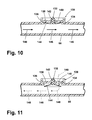
- Fig. 10 is a sectional view of the region labeled X in Fig. 9, wherein the anti-siphon device in the form of an umbrella valve is in a closed position.
- Fig. 11 is a sectional view similar to Fig. 10, wherein the umbrella valve is in an opened position.
- Fig. 12 is sectional view similar to Fig. 10, wherein the anti-siphon device is in the form of a duckbill valve in a closed position.
- Fig. 13 is a sectional view similar to Fig. 12, wherein the duckbill valve is in an opened position.
- Fig. 14 is a schematic view another alternative washing machine according to another embodiment of the invention, wherein a steam generator is positioned below a tub of the washing machine, and a generally ascending conduit couples the steam generator to the tub.
- Figs. 15A-15C are schematic views of the steam generator, the tub, and exemplary configurations of the generally ascending conduit.
- Fig. 16 is a schematic view of the washing machine of Fig. 14, wherein the steam generator is positioned adjacent to the tub, and the generally ascending conduit couples the steam generator to the tub.
- Fig. 1 is a schematic view of an exemplary fabric treatment appliance in the form of a washing machine 10 according to one embodiment of the invention.
- the fabric treatment appliance can be any machine that treats fabrics, and examples of the fabric treatment appliance include, but are not limited to, a washing machine, including top-loading, front-loading, vertical axis, and horizontal axis washing machines; a dryer, such as a tumble dryer or a stationary dryer, including top-loading dryers and front-loading dryers; a combination washing machine and dryer; a tumbling or stationary refreshing machine; an extractor; a non-aqueous washing apparatus; and a revitalizing machine.
- a washing machine including top-loading, front-loading, vertical axis, and horizontal axis washing machines
- a dryer such as a tumble dryer or a stationary dryer, including top-loading dryers and front-loading dryers
- a combination washing machine and dryer including top-loading dryers and front-loading dryers
- a combination washing machine and dryer
- the washing machine 10 of the illustrated embodiment comprises a cabinet 12 that houses a stationary tub 14.
- a rotatable drum 16 mounted within the tub 14 defines a fabric treatment chamber and includes a plurality of perforations 18, and liquid can flow between the tub 14 and the drum 16 through the perforations 18.
- the drum 16 further comprises a plurality of baffles 20 disposed on an inner surface of the drum 16 to lift fabric items contained in the drum 16 while the drum 16 rotates, as is well known in the washing machine art.
- a motor 22 coupled to the drum 16 through a belt 24 rotates the drum 16. Both the tub 14 and the drum 16 can be selectively closed by a door 26.
- Washing machines are typically categorized as either a vertical axis washing machine or a horizontal axis washing machine.
- the "vertical axis" washing machine refers to a washing machine comprising a rotatable drum, perforate or imperforate, that holds fabric items and a fabric moving element, such as an agitator, impeller, nutator, and the like, that induces movement of the fabric items to impart mechanical energy to the fabric articles for cleaning action.
- the drum rotates about a vertical axis generally perpendicular to a surface that supports the washing machine.
- the rotational axis need not be vertical.
- the drum can rotate about an axis inclined relative to the vertical axis.
- the "horizontal axis" washing machine refers to a washing machine having a rotatable drum, perforated or imperforate, that holds fabric items and washes the fabric items by the fabric items rubbing against one another as the drum rotates.
- the clothes are lifted by the rotating drum and then fall in response to gravity to form a tumbling action that imparts the mechanical energy to the fabric articles.
- the drum rotates about a horizontal axis generally parallel to a surface that supports the washing machine.
- the rotational axis need not be horizontal.
- the drum can rotate about an axis inclined relative to the horizontal axis.
- Vertical axis and horizontal axis machines are best differentiated by the manner in which they impart mechanical energy to the fabric articles.
- a clothes mover such as an agitator, auger, impeller, to name a few, moves within a wash basket to impart mechanical energy directly to the clothes or indirectly through wash liquid in the wash basket.
- the clothes mover is typically moved in a reciprocating rotational movement.
- the illustrated exemplary washing machine of Fig. 1 is a horizontal axis washing machine.
- the motor 22 can rotate the drum 16 at various speeds in opposite rotational directions.
- the motor 22 can rotate the drum 16 at tumbling speeds wherein the fabric items in the drum 16 rotate with the drum 16 from a lowest location of the drum 16 towards a highest location of the drum 16, but fall back to the lowest location of the drum 16 before reaching the highest location of the drum 16.
- the rotation of the fabric items with the drum 16 can be facilitated by the baffles 20.
- the motor 22 can rotate the drum 16 at spin speeds wherein the fabric items rotate with the drum 16 without falling.
- the liquid conduit 36 can couple with the tub 14 at any suitable location on the tub 14 and is shown as being coupled to a front wall of the tub 14 in Fig. 1 for exemplary purposes.
- the liquid that flows from the detergent dispenser 32 through the liquid conduit 36 to the tub 14 enters a space between the tub 14 and the drum 16 and flows by gravity to a sump 38 formed in part by a lower portion 40 of the tub 14.
- the sump 38 is also formed by a sump conduit 42 that fluidly couples the lower portion 40 of the tub 14 to a pump 44.
- the pump 44 can direct fluid to a drain conduit 46, which drains the liquid from the washing machine 10, or to a recirculation conduit 48, which terminates at a recirculation inlet 50.
- the recirculation inlet 50 directs the liquid from the recirculation conduit 48 into the drum 16.
- the recirculation inlet 50 can introduce the liquid into the drum 16 in any suitable manner, such as by spraying, dripping, or providing a steady flow of the liquid.
- the exemplary washing machine 10 further includes a steam generation system.
- the steam generation system comprises a steam generator 60 that receives liquid from the water supply 28 through a second supply conduit 62.
- the inlet valve 34 controls flow of the liquid from the water supply 28 and through the second supply conduit 62 to the steam generator 60.
- the inlet valve 34 can be positioned in any suitable location between the water supply 28 and the steam generator 60.
- a steam conduit 66 fluidly couples the steam generator 60 to a steam inlet 68, which introduces steam into the tub 14.
- the steam inlet 68 can couple with the tub 14 at any suitable location on the tub 14 and is shown as being coupled to a rear wall of the tub 14 in Fig. 1 for exemplary purposes.
- the steam that enters the tub 14 through the steam inlet 68 subsequently enters the drum 16 through the perforations 18.
- the steam inlet 68 can be configured to introduce the steam directly into the drum 16.
- the steam inlet 68 can introduce the steam into the tub 14 in any suitable manner.
- the steam generator 60 can be any type of device that converts the liquid to steam.
- the steam generator 60 can be a tank-type steam generator that stores a volume of liquid and heats the volume of liquid to convert the liquid to steam.
- the steam generator 60 can be an in-line steam generator that converts the liquid to steam as the liquid flows through the steam generator 60.
- the steam generator 60 can produce pressurized or non-pressurized steam.
- Exemplary steam generators are disclosed in our Docket Number US20050349 , S/N 11/450,528, titled “Removal of Scale and Sludge in a Steam Generator of a Fabric Treatment Appliance," our Docket Number US20050472 , S/N 11/450,836, titled “Prevention of Scale and Sludge in a Steam Generator of a Fabric Treatment Appliance,” and our Docket Number US20060227 , S/N 11/450,714, titled “Draining Liquid From a Steam Generator of a Fabric Treatment Appliance,” all filed June 9, 2006, in addition to the European patent applications all filed concurrently herewith our Docket Number US20050364 , titled “Water Supply Control for a Steam Generator of a Fabric Treatment Appliance," our Docket Number US20060254 , titled “Water Supply Control for a Steam Generator of a Fabric Treatment Appliance Using a Weight Sensor,” and our Docket Number US20060255 , titled “Water Supply Control for a Steam Generator of a Fabric Treatment Appliance Using
- the steam generator 60 can heat water to a temperature below a steam transformation temperature, whereby the steam generator 60 produces hot water.
- the hot water can be delivered to the tub 14 and/or drum 16 from the steam generator 60.
- the hot water can be used alone or can optionally mix with cold water in the tub 14 and/or drum 16. Using the steam generator to produce hot water can be useful when the steam generator 60 couples only with a cold water source of the water supply 28.
- the liquid supply and recirculation system and the steam generator system can differ from the configuration shown in Fig. 1, such as by inclusion of other valves, conduits, wash aid dispensers, and the like, to control the flow of liquid and steam through the washing machine 10 and for the introduction of more than one type of detergent/wash aid.
- a valve can be located in the liquid conduit 36, in the recirculation conduit 48, and in the steam conduit 66.
- an additional conduit can be included to couple the water supply 28 directly to the tub 14 or the drum 16 so that the liquid provided to the tub 14 or the drum 16 does not have to pass through the detergent dispenser 32.
- the liquid can be provided to the tub 14 or the drum 16 through the steam generator 60 rather than through the detergent dispenser 32 or the additional conduit.
- the liquid conduit 36 can be configured to supply liquid directly into the drum 16, and the recirculation conduit 48 can be coupled to the liquid conduit 36 so that the recirculated liquid enters the tub 14 or the drum 16 at the same location where the liquid from the detergent dispenser 32 enters the tub 14 or the drum 16.
- the washing machine 10 can further comprise a controller coupled to various working components of the washing machine 10, such as the pump 44, the motor 22, the inlet valve 34, the flow controller 64, the detergent dispenser 32, and the steam generator 60, to control the operation of the washing machine 10.
- the controller can receive data from the working components and can provide commands, which can be based on the received data, to the working components to execute a desired operation of the washing machine 10.
- the washing machine 10 can further include an exhaust system for managing steam exhaust from the tub 14.
- an exhaust system for managing steam exhaust from the tub 14. fabric items in the drum 16, liquid absorbed by the fabric items, and free liquid in the washing machine 10 absorb a portion of the steam, while a portion of the steam remains unabsorbed. Rotation of the drum 16 helps to retain the unabsorbed steam within the fabric treatment chamber, but at least some of the unabsorbed steam leaves the drum 16 and the tub 14 through an exhaust conduit 70.
- the exhaust conduit 70 fluidly couples the tub 14 to the detergent dispenser 32.
- the exhaust conduit 70 and the detergent dispenser 32 are shown more clearly in Fig. 2, which is a perspective view of the washing machine 10 with a top panel of the cabinet 12 removed.
- the exhaust conduit 70 can be coupled to a top portion of the tub 14, as shown in Fig. 2, or any other suitable portion of the tub 14. Because steam naturally rises, locating the exhaust conduit 70 at the top of the tub 14 takes advantage of the inherent flow behavior of the steam.
- the exhaust conduit 70 directs the steam to the detergent dispenser 32, and the steam enters the detergent dispenser 32 at a detergent dispenser steam inlet 72.
- the detergent dispenser 32 can function as a condenser whereby the steam converts from a vapor to water in the detergent dispenser.
- Using the detergent dispenser as a condenser of the exhaust system employs an existing component of the washing machine 10 and thereby reduces cost of the exhaust system.
- the detergent dispenser 32 has a temperature less than that of the steam and can contain liquid also having a lower temperature than that of the steam.
- the steam contacts the detergent dispenser 32 and any liquid contained in the detergent dispenser 32, heat transfers from the steam to the detergent dispenser 32 and the liquid.
- the temperature of the steam lowers to below a steam transformation temperature, and the steam converts to water.
- the water resulting from the condensation of the steam can remain in the detergent dispenser 32 for future use.
- the water in the detergent dispenser 32 can be drained, such as through the liquid conduit 36, the tub 14, the sump 38, and the pump 44 to the drain conduit 46.
- the detergent dispenser 32 does not condense all of the steam provided through the detergent dispenser steam inlet 72, then the excess steam can leave the detergent dispenser 32 and flow to the atmosphere external to the washing machine 10.
- the steam can flow through the access opening 33 (Figs. 1 and 2), whereby the access opening 33 forms a detergent dispenser steam outlet, or through a second exhaust conduit 74 coupling a detergent dispenser steam outlet 76 to the atmosphere external to the washing machine 10.
- the steam from the fabric treatment chamber can flow through a steam exhaust passage formed by the exhaust conduit 70 to the detergent dispenser 32, and the steam exhaust passage continues through either the access opening 33 or the second exhaust conduit 74 to the atmosphere.
- the second exhaust conduit 74 can ascend from the detergent dispenser steam outlet 76 to the atmosphere to take advantage of the natural upward flow behavior of steam.
- the second exhaust conduit 74 need not ascend at all locations between the detergent dispenser steam outlet 76 and the atmosphere.
- the connection between the second exhaust conduit 74 and the detergent dispenser steam outlet 76 should be positioned below the connection between the second exhaust conduit 94 and the atmosphere.
- FIG. 4 is a perspective view of the washing machine 10A with a top panel of the cabinet 12A removed, the exhaust system comprises an exhaust conduit 70A fluidly coupled to the tub 14A.
- the exhaust conduit 70A can be coupled to a top portion of the tub 14A, as shown in Fig. 4, or any other suitable portion of the tub 14A. Because steam naturally rises, locating the exhaust conduit 70A at the top of the tub 14A takes advantage of the inherent flow behavior of the steam.
- the exhaust conduit 70A directs the steam to a condenser 80.
- the condenser 80 can be coupled to the detergent dispenser 32A.
- the condenser 80 comprises a mounting bracket 78 that facilitates mounting the condenser 80 to the detergent dispenser 32A.
- the condenser 80 can be integrally formed with the detergent dispenser 32A.
- the condenser 80 comprises an open-front housing 82 closed by a cover 84.
- the housing 82 defines an upper, shower chamber 86 and a lower, condensing chamber 88 separated by a divider 90 having openings 92 that fluidly couple the shower chamber 86 to the condensing chamber 88.
- the condensing chamber 88 includes a plurality of ribs 94 and vertical walls 96 that define a labyrinth pathway through the condensing chamber 88 from a condenser steam inlet 98 to a condenser steam outlet 100, which is formed in the cover 84 in the illustrated embodiment.
- the exhaust conduit 70A couples to the condenser 80 at the condenser steam inlet 98.
- a second exhaust conduit 74A fluidly couples the condenser steam outlet 100 to the atmosphere external to the washing machine 10A (Figs. 4 and 5).
- the condenser 80 further includes a condenser water inlet 104, which is formed in the cover 84 in the illustrated embodiment, coupled to the water supply 28A via a condenser water conduit 106 (Figs. 4 and 5).
- the condenser water conduit 106 can branch from the first supply conduit 30A to the detergent dispenser 32A or can be separately coupled to the inlet valve 34A.
- the condenser water conduit 106 can be coupled to the second supply conduit 62A that provides water from the water supply 28A to the steam generator 60A.
- a valve can be positioned in the condenser water conduit 106 to control the flow of water to the condenser 80.
- the water from the water supply 28A can enter the shower chamber 86 through the condenser water inlet 104 and flow into the condensing chamber 88 via the openings 92 in the divider 90.
- the ribs 94 in the condensing chamber 88 can be configured, such as by being generally V-shaped, to form a well 108 that can hold water flowing from the shower chamber 86.
- the condenser 80 further includes a reservoir 110 formed at the bottom of the condensing chamber 88. Above the reservoir 110, a steam barrier 112 in the form of a generally vertical wall separates the condensing chamber 88 from a condenser water outlet 114.
- the steam barrier 112 and the water in the reservoir 110 prevent steam from leaking from the labyrinth path in the condensing chamber 88 to the condenser water outlet 114.
- the condenser water outlet 114 fluidly couples the condenser 80 with the detergent dispenser 32A via an aperture 116 in the detergent dispenser 32A.
- exhaust steam from the fabric treatment chamber flows through the exhaust conduit 70A to the condenser steam inlet 98, where the steam enters the labyrinth path in the condensing chamber 88.
- the steam contacts the ribs 94, and heat transfer between the steam and the ribs 94 facilitates condensing the steam.
- cold water flowing from the shower chamber 86 into the wells 108 of the ribs 94 cools the ribs 94 to further facilitate heat transfer between the ribs 94 and the steam.
- the steam condenses to water, which collects in the reservoir 110.
- the reservoir 110 can hold water from condensed steam, water overflowing from the wells 108, and water provided directly from the shower chamber 86.
- the water level in the reservoir 110 increases, such as due to steam condensation, the water reaches the condenser water outlet 114 and leaves the condenser 80 through the condenser water outlet 114.
- the water flows into the detergent dispenser 32A through the aperture 116.
- the water supplied to the detergent dispenser 32A from the condenser 80 can remain in the detergent dispenser 32A for future use.
- the water in the detergent dispenser 32A can be drained in the manner described above for the first embodiment exhaust system.
- the condenser 80 does not condense all of the steam provided through the condenser steam inlet 98, then the excess steam can leave the condenser 80 and flow to the atmosphere external to the washing machine 10A.
- the steam flows through the condenser steam outlet 100 and the second exhaust conduit 74A to the atmosphere external to the washing machine 10A.
- the steam from the fabric treatment chamber can flow through a steam exhaust passage formed by the exhaust conduit 70A to the condenser 80, and the steam exhaust passage continues through the second exhaust conduit 74A to the atmosphere.
- the second exhaust conduit 74A can ascend from the condenser steam outlet 100 to the atmosphere to take advantage of the natural upward flow behavior of steam.
- the second exhaust conduit 74A need not ascend at all locations between the condenser steam outlet 100 and the atmosphere.
- the connection between the second exhaust conduit 74A and the condenser steam outlet 100 should be positioned below the connection between the second exhaust conduit 74A and the atmosphere.
- the washing machine 10 can exhaust the steam from the fabric treatment chamber through an exhaust conduit that exhausts the steam directly to the atmosphere, as illustrated in Fig. 7.
- Fig. 7 shows another embodiment washing machine 10B.
- the components of the washing machine 10B similar to those of the first and second embodiment washing machines 10, 10A are identified with the same reference numeral bearing the letter "B.”
- the washing machine 10B is essentially identical to the first embodiment washing machine 10, except that the exhaust conduit 70B is coupled directly to the atmosphere rather than being coupled to the detergent dispenser 32B.
- the washing machine 10 can include a temperature sensor 120 configured to determine a temperature representative of the exhaust from the fabric treatment chamber.
- the temperature sensor 120 can be a device that senses a temperature of the exhaust from the fabric treatment chamber.
- the temperature sensor 120 can be a thermistor or any other well-known type of temperature sensor.
- the temperature sensor 120 can be positioned in the exhaust conduit 70, as shown in Fig. 1, to determine the temperature of the exhaust in the exhaust conduit 70.
- the temperature sensor 120 can be positioned in any suitable location to determine a temperature representative of the exhaust from the fabric treatment chamber.
- the temperature sensor 120 can be positioned entirely within the exhaust conduit 70, partially within the exhaust conduit 70, externally of the exhaust conduit 70, or spaced from the exhaust conduit 70.
- the temperature sensor 120 can be located any suitable distance from the connection between the exhaust conduit 70 and the tub 14.
- the temperature sensor 120 can be positioned at or near the connection between the exhaust conduit 70 and the tub 14. As the position of the temperature sensor 120 nears the fabric treatment chamber, the difference between the temperature of the fabric items and the temperature determined by the temperature sensor 120 decreases.
- the temperature sensor 120 can be coupled to the controller of the washing machine 10 to communicate the determined temperature representative of the exhaust to the controller.
- the controller can utilize the determined temperature to determine a temperature of fabric items in the fabric treatment chamber.
- the controller can store a relationship between the temperature of the fabric items and the determined temperature and utilize the relationship to determine the temperature of the fabric items.
- the relationship between the temperature of the fabric items and the determined temperature can be an empirically determined relationship.
- the temperature of the fabric items and the determined temperature can differ by an empirically determined quantity.
- Fig. 8 presents a graph showing an exemplary relationship between the temperature of the fabric items and the determined temperature for a 7 kg fabric load and a laundry weight to water weight ratio of 1:2.
- the difference between the temperature of the fabric items and the determined temperature is about 10 °C.
- the temperature of the fabric items in the illustrated example can be estimated by adding about 10 °C, which can be considered a correction factor, to the determined temperature.
- the controller can utilize the determined temperature to control the operation of the washing machine 10 or individual components of the washing machine 10.
- the controller can be configured to convert the determined temperature to the temperature of the fabric items and control the operation of the washing machine 10 based on the temperature of the fabric items.
- the controller can be configured to control the operation of the washing machine 10 without converting the determined temperature to the temperature of the fabric items.
- the controller can control the washing machine 10 in any suitable manner.
- the controller can control the operation of the steam generator 60 based on the determined temperature.
- the operation of the steam generator 60 can include, by example, initiating steam generation, stopping steam generation, controlling water flow into the steam generator 60, and controlling a steam generation rate, such as by controlling a heater of the steam generator 60.
- the temperature sensor 120 can be employed on any type of fabric treatment appliance and washing machines other than the washing machine 10 of Fig. 1.
- the temperature sensor 120 can be utilized in conjunction with the washing machines 10A, 10B of Figs. 4 and 7.
- the exhaust conduit 70 can have any suitable configuration, such as being coupled to a condenser or directly to the atmosphere exterior of the washing machine 10.
- the temperature sensor 120 can be employed with any type of steam generator 60, including, but not limited to, in-line steam generators and tank-type steam generators.
- the difference between the temperature of the fabric items and the determined temperature decreases as the position of the temperature sensor 120 nears the fabric treatment chamber. Moving the temperature sensor 120 closer to the fabric treatment chamber, therefore, results in the detected temperature approaching the temperature of the fabric items. For this reason, the temperature sensor 120 can be positioned in the tub 14; however, the temperature sensor 120 is easier to service and the washing machine 10 is less expensive to manufacture when the temperature sensor 120 is located in the exhaust conduit 70.
- the washing machine 10 can further comprise an anti-siphon device 130.
- the anti-siphon device 130 is more clearly shown in Fig. 9, which is a schematic view of the inlet valve 34, the second supply conduit 62, the steam generator 60, the steam conduit 66, the tub 14, the drum 16, and the anti-siphon device 130.
- pressure within the steam conduit 66 can draw (i.e., siphon) liquid from the tub 14 and/or the drum 16 into the steam conduit 66 and to the steam generator 60.
- the liquid can contain detergents or other wash aids that can potentially detrimentally affect the performance of the steam generator 60, and if the siphon draws a sufficient amount of liquid from the tub 14 and/or the drum 16, the liquid can overflow the steam generator 60 and reach the inlet valve 34.
- the anti-siphon device 130 prevents the backflow of liquid from the tub 14 and/or the drum 16 to the steam generator 60.
- the anti-siphon device 130 is located in the steam conduit 66 downstream from the steam generator 60. It is within the scope of the invention, however, to locate the anti-siphon device 130 anywhere between the inlet valve 34 and the tub 14 and/or the drum 16.
- the anti-siphon device 130 controls flow of air from atmosphere external to the steam conduit 66 into the steam conduit 66 by selectively opening the steam conduit 66 to the atmosphere.
- the atmosphere external to the steam conduit 66 can be atmosphere within the washing machine 10 or external to the washing machine 10.
- the anti-siphon device 130 can be any suitable type of device that can control the flow of air.
- the anti-siphon device 130 can be a valve, such as a check valve that allows air to flow from the atmosphere into the steam conduit 66 but does not allow steam to pass from the steam conduit 66 to the atmosphere. Examples of the anti-siphon device 130 in the form of a check valve are illustrated in Figs. 10-13.
- Fig. 10 presents a sectional view of the steam conduit 66 and the anti-siphon device 130 in the form of an umbrella valve 132.
- the umbrella valve 132 resides within an opening 134 in the steam conduit 66.
- the opening 134 fluidly couples the atmosphere to the interior of the steam conduit 66, and the umbrella valve 132 selectively closes the opening 134.
- the umbrella valve 132 comprises a housing 136 and a valve support 138 mounted to the housing 136.
- the valve support 138 forms an aperture 140 and supports a valve member 142 having a resilient diaphragm 144.
- the aperture 140 fluidly couples the atmosphere to the steam conduit 66, and the diaphragm 144 has a normally closed position, as shown in Fig.
- the predetermined pressure can be any suitable pressure, such as a pressure below atmospheric pressure.
- suitable pressures below atmospheric pressure are pressures less than or equal to about 0.5 bar.
- Fig. 12 presents a sectional view of the steam conduit 66 and the anti-siphon device 130 in the form of a duckbill valve 150.
- the duckbill valve 150 resides within an opening 152 in the steam conduit 66.
- the opening 152 fluidly couples the atmosphere to the interior of the steam conduit 66, and the duckbill valve 150 selectively closes the opening 152.
- the duckbill valve 150 comprises a housing 154 that forms an aperture 156 and supports a valve member 158 located in the aperture 156 and having an air passageway 160.
- the aperture 156 fluidly couples the atmosphere to the steam conduit 66, and the valve member 158 has a normally closed position, as shown in Fig. 12, where the valve member 158 contracts to close the air passageway 160 and thereby closes the aperture 156.
- valve member 158 when the valve member 158 is in the closed position, the valve member 158 prevents fluid communication between the atmosphere and the steam conduit 66, and steam from the steam generator 60 can flow through the steam conduit 66 to the tub 14 and/or the drum 16, as indicated by solid arrows 162 in Fig. 12.
- the valve member 158 moves to an opened position, as shown in Fig. 13, where the valve member 158 expands to open the air passageway 160 and no longer close the aperture 156.
- the valve member 158 is in the opened position, air from the atmosphere can flow through the aperture 156 and into the steam conduit 66, as indicated by dashed arrows 164 in Fig. 13.
- the predetermined pressure can be any suitable pressure, such as a pressure below atmospheric pressure.
- suitable pressures below atmospheric pressure are pressures less than or equal to about 0.5 bar.
- the anti-siphon device 130 can be employed on any type of fabric treatment appliance and washing machines other than the washing machine 10 of Fig. 1.
- the anti-siphon device 130 can be utilized in conjunction with the washing machines 10A, 10B of Figs. 4 and 7.
- the anti-siphon device 130 can be employed with any type of steam generator 60, including, but not limited to, in-line steam generators and tank-type steam generators.
- FIG. 14 An alternative embodiment washing machine 10 is illustrated schematically in Fig. 14, where components similar to those of the first embodiment washing machine 10 of Fig. 1 are identified with the same numeral bearing the letter "C.”
- the alternative embodiment washing machine 10C is substantially identical to the washing machine 10 of Fig. 1, except for the location of the steam generator 60C and the steam conduit 66C.
- the steam generator 60C is positioned below the tub 14C, and the steam conduit 66C, which has an inlet 170 fluidly coupled to the steam generator 60C and an outlet 172 fluidly coupled to the tub 14C, generally ascends from the steam generator 60C to the tub 14C.
- the steam conduit 66C takes advantage of the natural tendency of the steam to rise for delivery of the steam to the tub 14C and/or the drum 16C.
- Using the generally ascending configuration is especially useful when the steam is not pressurized; the generally ascending configuration can guide the rising steam from the steam generator 60C to the tub 14C and/or the drum 16C.
- the pressure forces the steam through the steam conduit, regardless of the configuration of the steam conduit.
- the steam conduit 66C is configured such that the outlet 172 defines a high point (i.e., the most vertical point) of the steam conduit 66C.
- the steam will continue to flow within the steam conduit 66C and rise until it reaches the outlet 172 for delivery into the tub 14 and/or the drum 16.
- the steam conduit 66C does not have to be entirely ascending; it can comprise ascending portions, descending portions, horizontal portions, and combinations thereof.
- the steam conduit 66C in Fig. 14 comprises a first generally horizontal portion 174 near the inlet 170, a second generally horizontal portion 176 near the outlet 172, and an ascending portion 178 between the first and second horizontal portions 174, 176.
- FIG. 15A the steam conduit 66C comprises only an ascending portion 178.
- the steam conduit 66C of Fig. 15B comprises a descending portion 180 between a pair of ascending portions 178.
- the steam conduit 66C comprises a descending portion 180 between two ascending portions 178 and a horizontal portion 174 between one of the ascending portions 178 and the steam generator 60C.
- the steam generator 60C For the steam conduit 66C to be generally ascending when the steam conduit 66C is coupled to the tub 14C and/or the drum 16C, the steam generator 60C must be located below a high point of the tub 14C and/or the drum 16C. As stated above, the steam generator 60C in Fig. 14 is located below the tub 14C. The steam generator 60C can also be located adjacent to the tub 14C and/or the drum 16C, as illustrated in Fig. 16.
- the generally ascending steam conduit 66C can be employed on any type of fabric treatment appliance and washing machines other than the washing machine 10C of Figs. 14 and 16. Further, the generally ascending steam conduit 66C can be employed with any type of steam generator 60C, including, but not limited to, in-line steam generators and tank-type steam generators.
- washing machines 10, 10A, 10B, 10C can be used in conjunction with one another or independently of one another.
- the steam exhaust conduit 70 (either coupled to a condenser or coupled directly to the atmosphere), the temperature sensor 120, the anti-siphon device 130, and the generally ascending steam conduit 66C can be employed in any combination or alone in a fabric treatment appliance
Abstract
Description
- The invention relates to a fabric treatment appliance with a steam generator.
- Some fabric treatment appliances, such as a washing machine, a clothes dryer, and a fabric refreshing or revitalizing machine, utilize steam generators for various reasons. The steam from the steam generator can be used to, for example, heat water, heat a load of fabric items and any water absorbed by the fabric items, dewrinkle fabric items, remove odors from fabric items, etc.
- In some fabric treatment appliances, the steam generator, positioned externally of a fabric treatment chamber and fluidly coupled to the fabric treatment chamber, such as by a conduit, delivers steam to the fabric treatment chamber. The steam generator receives water from a water supply, converts the water to steam, and delivers the steam to the fabric treatment chamber via the conduit. During operation of the fabric treatment appliance, a siphon effect can develop within the conduit that couples the steam generator to the fabric treatment chamber, whereby liquid from the fabric treatment chamber flows through the conduit to the steam generator. Such a condition is undesirable because the liquid can contain wash aids or other chemicals that could detrimentally affect the performance of the steam generator. Additionally, if the siphon effect draws more liquid from the fabric treatment chamber than the capacity of the steam generator, the liquid can flow from the steam generator to the water supply.
- The invention relates to a fabric treatment appliance comprising at least one of a tub and drum defining a fabric treatment chamber. A steam generator is coupled by a conduit to the at least one of the tub and drum to supply steam to the fabric treatment chamber. An anti-siphon device is located in the steam conduit and is configured to prevent flow of liquid from the at least one of the tub and drum to the steam generator.
- The invention will be further described by way of example with reference to the accompanying drawings, in which:-
- Fig. 1 is a schematic view of a fabric treatment appliance in the form of a washing machine according to one embodiment of the invention.
- Fig. 2 is a perspective view of the washing machine of Fig. 1 with a top panel of a cabinet removed.
- Fig. 3 is a perspective view of select components of an exhaust system, a steam generator system, and a liquid supply and recirculation system of the washing machine of Figs. 1 and 2.
- Fig. 4 is a perspective view of an alternative washing machine according to another embodiment of the invention with a top panel of a cabinet removed.
- Fig. 5 is a perspective view of select components of an exhaust system, a steam generator system, and a liquid supply and recirculation system of the washing machine of Fig. 4.
- Fig. 6 is a perspective view of a detergent dispenser and condenser from the washing machine of Fig. 4.
- Fig. 7 is a perspective view of another alternative washing machine according to another embodiment of the invention with a top panel of a cabinet removed
- Fig. 8 is a graph depicting an exemplary differential between temperature of a fabric load and temperature determined by a temperature sensor from the washing machine of Fig. 1.
- Fig. 9 is a schematic view of select components, including an anti-siphon device, of the washing machine of Fig. 1.
- Fig. 10 is a sectional view of the region labeled X in Fig. 9, wherein the anti-siphon device in the form of an umbrella valve is in a closed position.
- Fig. 11 is a sectional view similar to Fig. 10, wherein the umbrella valve is in an opened position.
- Fig. 12 is sectional view similar to Fig. 10, wherein the anti-siphon device is in the form of a duckbill valve in a closed position.
- Fig. 13 is a sectional view similar to Fig. 12, wherein the duckbill valve is in an opened position.
- Fig. 14 is a schematic view another alternative washing machine according to another embodiment of the invention, wherein a steam generator is positioned below a tub of the washing machine, and a generally ascending conduit couples the steam generator to the tub.
- Figs. 15A-15C are schematic views of the steam generator, the tub, and exemplary configurations of the generally ascending conduit.
- Fig. 16 is a schematic view of the washing machine of Fig. 14, wherein the steam generator is positioned adjacent to the tub, and the generally ascending conduit couples the steam generator to the tub.
- Referring now to the figures, Fig. 1 is a schematic view of an exemplary fabric treatment appliance in the form of a
washing machine 10 according to one embodiment of the invention. The fabric treatment appliance can be any machine that treats fabrics, and examples of the fabric treatment appliance include, but are not limited to, a washing machine, including top-loading, front-loading, vertical axis, and horizontal axis washing machines; a dryer, such as a tumble dryer or a stationary dryer, including top-loading dryers and front-loading dryers; a combination washing machine and dryer; a tumbling or stationary refreshing machine; an extractor; a non-aqueous washing apparatus; and a revitalizing machine. For illustrative purposes, the invention will be described with respect to a washing machine, with it being understood that the invention can be adapted for use with any type of fabric treatment appliance having a steam generator. - The
washing machine 10 of the illustrated embodiment comprises acabinet 12 that houses astationary tub 14. Arotatable drum 16 mounted within thetub 14 defines a fabric treatment chamber and includes a plurality ofperforations 18, and liquid can flow between thetub 14 and thedrum 16 through theperforations 18. Thedrum 16 further comprises a plurality ofbaffles 20 disposed on an inner surface of thedrum 16 to lift fabric items contained in thedrum 16 while thedrum 16 rotates, as is well known in the washing machine art. Amotor 22 coupled to thedrum 16 through abelt 24 rotates thedrum 16. Both thetub 14 and thedrum 16 can be selectively closed by adoor 26. - Washing machines are typically categorized as either a vertical axis washing machine or a horizontal axis washing machine. As used herein, the "vertical axis" washing machine refers to a washing machine comprising a rotatable drum, perforate or imperforate, that holds fabric items and a fabric moving element, such as an agitator, impeller, nutator, and the like, that induces movement of the fabric items to impart mechanical energy to the fabric articles for cleaning action. In some vertical axis washing machines, the drum rotates about a vertical axis generally perpendicular to a surface that supports the washing machine. However, the rotational axis need not be vertical. The drum can rotate about an axis inclined relative to the vertical axis. As used herein, the "horizontal axis" washing machine refers to a washing machine having a rotatable drum, perforated or imperforate, that holds fabric items and washes the fabric items by the fabric items rubbing against one another as the drum rotates. In horizontal axis washing machines, the clothes are lifted by the rotating drum and then fall in response to gravity to form a tumbling action that imparts the mechanical energy to the fabric articles. In some horizontal axis washing machines, the drum rotates about a horizontal axis generally parallel to a surface that supports the washing machine. However, the rotational axis need not be horizontal. The drum can rotate about an axis inclined relative to the horizontal axis. Vertical axis and horizontal axis machines are best differentiated by the manner in which they impart mechanical energy to the fabric articles. In vertical axis machines a clothes mover, such as an agitator, auger, impeller, to name a few, moves within a wash basket to impart mechanical energy directly to the clothes or indirectly through wash liquid in the wash basket. The clothes mover is typically moved in a reciprocating rotational movement. The illustrated exemplary washing machine of Fig. 1 is a horizontal axis washing machine.
- The
motor 22 can rotate thedrum 16 at various speeds in opposite rotational directions. In particular, themotor 22 can rotate thedrum 16 at tumbling speeds wherein the fabric items in thedrum 16 rotate with thedrum 16 from a lowest location of thedrum 16 towards a highest location of thedrum 16, but fall back to the lowest location of thedrum 16 before reaching the highest location of thedrum 16. The rotation of the fabric items with thedrum 16 can be facilitated by thebaffles 20. Alternatively, themotor 22 can rotate thedrum 16 at spin speeds wherein the fabric items rotate with thedrum 16 without falling. - The
washing machine 10 of Fig. 1 further comprises a liquid supply and recirculation system. Liquid, such as water, can be supplied to thewashing machine 10 from ahousehold water supply 28. A first supply conduit 30 fluidly couples thewater supply 28 to adetergent dispenser 32. Thedetergent dispenser 32 can be accessed by a user through an access opening 33 in thecabinet 12, such as for providing a wash aid to thedetergent dispenser 32. Aninlet valve 34 controls flow of the liquid from thewater supply 28 and through thefirst supply conduit 30 to thedetergent dispenser 32. Theinlet valve 34 can be positioned in any suitable location between thewater supply 28 and thedetergent dispenser 32. Aliquid conduit 36 fluidly couples thedetergent dispenser 32 with thetub 14. Theliquid conduit 36 can couple with thetub 14 at any suitable location on thetub 14 and is shown as being coupled to a front wall of thetub 14 in Fig. 1 for exemplary purposes. The liquid that flows from thedetergent dispenser 32 through theliquid conduit 36 to thetub 14 enters a space between thetub 14 and thedrum 16 and flows by gravity to asump 38 formed in part by alower portion 40 of thetub 14. Thesump 38 is also formed by asump conduit 42 that fluidly couples thelower portion 40 of thetub 14 to apump 44. Thepump 44 can direct fluid to adrain conduit 46, which drains the liquid from thewashing machine 10, or to arecirculation conduit 48, which terminates at arecirculation inlet 50. Therecirculation inlet 50 directs the liquid from therecirculation conduit 48 into thedrum 16. Therecirculation inlet 50 can introduce the liquid into thedrum 16 in any suitable manner, such as by spraying, dripping, or providing a steady flow of the liquid. - The
exemplary washing machine 10 further includes a steam generation system. The steam generation system comprises asteam generator 60 that receives liquid from thewater supply 28 through asecond supply conduit 62. Theinlet valve 34 controls flow of the liquid from thewater supply 28 and through thesecond supply conduit 62 to thesteam generator 60. Theinlet valve 34 can be positioned in any suitable location between thewater supply 28 and thesteam generator 60. Asteam conduit 66 fluidly couples thesteam generator 60 to asteam inlet 68, which introduces steam into thetub 14. Thesteam inlet 68 can couple with thetub 14 at any suitable location on thetub 14 and is shown as being coupled to a rear wall of thetub 14 in Fig. 1 for exemplary purposes. The steam that enters thetub 14 through thesteam inlet 68 subsequently enters thedrum 16 through theperforations 18. Alternatively, thesteam inlet 68 can be configured to introduce the steam directly into thedrum 16. Thesteam inlet 68 can introduce the steam into thetub 14 in any suitable manner. - The
steam generator 60 can be any type of device that converts the liquid to steam. For example, thesteam generator 60 can be a tank-type steam generator that stores a volume of liquid and heats the volume of liquid to convert the liquid to steam. Alternatively, thesteam generator 60 can be an in-line steam generator that converts the liquid to steam as the liquid flows through thesteam generator 60. Thesteam generator 60 can produce pressurized or non-pressurized steam. - Exemplary steam generators are disclosed in our Docket Number
US20050349 US20050472 US20060227 US20050364 US20060254 US20060255 - In addition to producing steam, the
steam generator 60, whether an in-line steam generator, a tank-type steam generator, or any other type of steam generator, can heat water to a temperature below a steam transformation temperature, whereby thesteam generator 60 produces hot water. The hot water can be delivered to thetub 14 and/or drum 16 from thesteam generator 60. The hot water can be used alone or can optionally mix with cold water in thetub 14 and/ordrum 16. Using the steam generator to produce hot water can be useful when thesteam generator 60 couples only with a cold water source of thewater supply 28. - The liquid supply and recirculation system and the steam generator system can differ from the configuration shown in Fig. 1, such as by inclusion of other valves, conduits, wash aid dispensers, and the like, to control the flow of liquid and steam through the
washing machine 10 and for the introduction of more than one type of detergent/wash aid. For example, a valve can be located in theliquid conduit 36, in therecirculation conduit 48, and in thesteam conduit 66. Furthermore, an additional conduit can be included to couple thewater supply 28 directly to thetub 14 or thedrum 16 so that the liquid provided to thetub 14 or thedrum 16 does not have to pass through thedetergent dispenser 32. Alternatively, the liquid can be provided to thetub 14 or thedrum 16 through thesteam generator 60 rather than through thedetergent dispenser 32 or the additional conduit. As another example, theliquid conduit 36 can be configured to supply liquid directly into thedrum 16, and therecirculation conduit 48 can be coupled to theliquid conduit 36 so that the recirculated liquid enters thetub 14 or thedrum 16 at the same location where the liquid from thedetergent dispenser 32 enters thetub 14 or thedrum 16. - Other alternatives for the liquid supply and recirculation system are disclosed in our Docket Number
US20050365 US20060177 US20060178 - The
washing machine 10 can further comprise a controller coupled to various working components of thewashing machine 10, such as thepump 44, themotor 22, theinlet valve 34, the flow controller 64, thedetergent dispenser 32, and thesteam generator 60, to control the operation of thewashing machine 10. The controller can receive data from the working components and can provide commands, which can be based on the received data, to the working components to execute a desired operation of thewashing machine 10. - The
washing machine 10 can further include an exhaust system for managing steam exhaust from thetub 14. During operation of thewashing machine 10, fabric items in thedrum 16, liquid absorbed by the fabric items, and free liquid in thewashing machine 10 absorb a portion of the steam, while a portion of the steam remains unabsorbed. Rotation of thedrum 16 helps to retain the unabsorbed steam within the fabric treatment chamber, but at least some of the unabsorbed steam leaves thedrum 16 and thetub 14 through anexhaust conduit 70. In the exhaust system of Fig. 1, theexhaust conduit 70 fluidly couples thetub 14 to thedetergent dispenser 32. Theexhaust conduit 70 and thedetergent dispenser 32 are shown more clearly in Fig. 2, which is a perspective view of thewashing machine 10 with a top panel of thecabinet 12 removed. Theexhaust conduit 70 can be coupled to a top portion of thetub 14, as shown in Fig. 2, or any other suitable portion of thetub 14. Because steam naturally rises, locating theexhaust conduit 70 at the top of thetub 14 takes advantage of the inherent flow behavior of the steam. - Referring now to Fig. 3, which is a perspective view of certain components of the exhaust system, the steam generator system, and the liquid supply and recirculation system, the
exhaust conduit 70 directs the steam to thedetergent dispenser 32, and the steam enters thedetergent dispenser 32 at a detergentdispenser steam inlet 72. Thedetergent dispenser 32 can function as a condenser whereby the steam converts from a vapor to water in the detergent dispenser. Using the detergent dispenser as a condenser of the exhaust system employs an existing component of thewashing machine 10 and thereby reduces cost of the exhaust system. Thedetergent dispenser 32 has a temperature less than that of the steam and can contain liquid also having a lower temperature than that of the steam. Consequently, when the steam contacts thedetergent dispenser 32 and any liquid contained in thedetergent dispenser 32, heat transfers from the steam to thedetergent dispenser 32 and the liquid. As the steam loses heat, the temperature of the steam lowers to below a steam transformation temperature, and the steam converts to water. The water resulting from the condensation of the steam can remain in thedetergent dispenser 32 for future use. Optionally, the water in thedetergent dispenser 32 can be drained, such as through theliquid conduit 36, thetub 14, thesump 38, and thepump 44 to thedrain conduit 46. - If the
detergent dispenser 32 does not condense all of the steam provided through the detergentdispenser steam inlet 72, then the excess steam can leave thedetergent dispenser 32 and flow to the atmosphere external to thewashing machine 10. For example, the steam can flow through the access opening 33 (Figs. 1 and 2), whereby the access opening 33 forms a detergent dispenser steam outlet, or through asecond exhaust conduit 74 coupling a detergentdispenser steam outlet 76 to the atmosphere external to thewashing machine 10. Thus, in the exemplary exhaust system just described, the steam from the fabric treatment chamber can flow through a steam exhaust passage formed by theexhaust conduit 70 to thedetergent dispenser 32, and the steam exhaust passage continues through either the access opening 33 or thesecond exhaust conduit 74 to the atmosphere. - Optionally, the
second exhaust conduit 74 can ascend from the detergentdispenser steam outlet 76 to the atmosphere to take advantage of the natural upward flow behavior of steam. In such a configuration, thesecond exhaust conduit 74 need not ascend at all locations between the detergentdispenser steam outlet 76 and the atmosphere. To exploit the natural upward flow of the steam, the connection between thesecond exhaust conduit 74 and the detergentdispenser steam outlet 76 should be positioned below the connection between thesecond exhaust conduit 94 and the atmosphere. - An alternative exhaust system is illustrated in Figs. 4-6 with respect to an alternative
exemplary washing machine 10A. The components of thewashing machine 10A similar to those of the firstembodiment washing machine 10 are identified with the same reference numeral bearing the letter "A." Referring particularly to Fig. 4, which is a perspective view of thewashing machine 10A with a top panel of thecabinet 12A removed, the exhaust system comprises anexhaust conduit 70A fluidly coupled to thetub 14A. As with the previous embodiment of the exhaust system, theexhaust conduit 70A can be coupled to a top portion of thetub 14A, as shown in Fig. 4, or any other suitable portion of thetub 14A. Because steam naturally rises, locating theexhaust conduit 70A at the top of thetub 14A takes advantage of the inherent flow behavior of the steam. - Referring now to Fig. 5, which is a perspective view of certain components of the exhaust system, the steam generator system, and the liquid supply and recirculation system, the
exhaust conduit 70A directs the steam to acondenser 80. As shown in the illustrated embodiment, thecondenser 80 can be coupled to thedetergent dispenser 32A. Thecondenser 80 comprises a mountingbracket 78 that facilitates mounting thecondenser 80 to thedetergent dispenser 32A. Alternatively, thecondenser 80 can be integrally formed with thedetergent dispenser 32A. - Referring now to Fig. 6, which is an exploded view of the
condenser 80 and thedetergent dispenser 32A, thecondenser 80 comprises an open-front housing 82 closed by acover 84. Thehousing 82 defines an upper,shower chamber 86 and a lower, condensingchamber 88 separated by adivider 90 havingopenings 92 that fluidly couple theshower chamber 86 to the condensingchamber 88. The condensingchamber 88 includes a plurality ofribs 94 andvertical walls 96 that define a labyrinth pathway through the condensingchamber 88 from acondenser steam inlet 98 to acondenser steam outlet 100, which is formed in thecover 84 in the illustrated embodiment. Theexhaust conduit 70A couples to thecondenser 80 at thecondenser steam inlet 98. Asecond exhaust conduit 74A fluidly couples thecondenser steam outlet 100 to the atmosphere external to thewashing machine 10A (Figs. 4 and 5). - The
condenser 80 further includes acondenser water inlet 104, which is formed in thecover 84 in the illustrated embodiment, coupled to the water supply 28A via a condenser water conduit 106 (Figs. 4 and 5). Thecondenser water conduit 106 can branch from thefirst supply conduit 30A to thedetergent dispenser 32A or can be separately coupled to theinlet valve 34A. Alternatively, thecondenser water conduit 106 can be coupled to thesecond supply conduit 62A that provides water from the water supply 28A to thesteam generator 60A. When thecondenser water conduit 106 branches from thefirst supply conduit 30A or thesecond supply conduit 62A, a valve can be positioned in thecondenser water conduit 106 to control the flow of water to thecondenser 80. - The water from the water supply 28A can enter the
shower chamber 86 through thecondenser water inlet 104 and flow into the condensingchamber 88 via theopenings 92 in thedivider 90. Theribs 94 in the condensingchamber 88 can be configured, such as by being generally V-shaped, to form a well 108 that can hold water flowing from theshower chamber 86. Thecondenser 80 further includes areservoir 110 formed at the bottom of the condensingchamber 88. Above thereservoir 110, asteam barrier 112 in the form of a generally vertical wall separates the condensingchamber 88 from acondenser water outlet 114. When thereservoir 110 holds a sufficient amount of water such that the water reaches at least a lowest point of thesteam barrier 112, thesteam barrier 112 and the water in thereservoir 110 prevent steam from leaking from the labyrinth path in the condensingchamber 88 to thecondenser water outlet 114. Thecondenser water outlet 114 fluidly couples thecondenser 80 with thedetergent dispenser 32A via anaperture 116 in thedetergent dispenser 32A. - In operation, exhaust steam from the fabric treatment chamber flows through the
exhaust conduit 70A to thecondenser steam inlet 98, where the steam enters the labyrinth path in the condensingchamber 88. As the steam flows through the labyrinth path, the steam contacts theribs 94, and heat transfer between the steam and theribs 94 facilitates condensing the steam. Additionally, cold water flowing from theshower chamber 86 into thewells 108 of theribs 94 cools theribs 94 to further facilitate heat transfer between theribs 94 and the steam. The steam condenses to water, which collects in thereservoir 110. Thus, thereservoir 110 can hold water from condensed steam, water overflowing from thewells 108, and water provided directly from theshower chamber 86. As the water level in thereservoir 110 increases, such as due to steam condensation, the water reaches thecondenser water outlet 114 and leaves thecondenser 80 through thecondenser water outlet 114. The water flows into thedetergent dispenser 32A through theaperture 116. The water supplied to thedetergent dispenser 32A from thecondenser 80 can remain in thedetergent dispenser 32A for future use. Optionally, the water in thedetergent dispenser 32A can be drained in the manner described above for the first embodiment exhaust system. - If the
condenser 80 does not condense all of the steam provided through thecondenser steam inlet 98, then the excess steam can leave thecondenser 80 and flow to the atmosphere external to thewashing machine 10A. At the end of the labyrinth path, the steam flows through thecondenser steam outlet 100 and thesecond exhaust conduit 74A to the atmosphere external to thewashing machine 10A. Thus, in the exemplary exhaust system just described, the steam from the fabric treatment chamber can flow through a steam exhaust passage formed by theexhaust conduit 70A to thecondenser 80, and the steam exhaust passage continues through thesecond exhaust conduit 74A to the atmosphere. - Optionally, the
second exhaust conduit 74A can ascend from thecondenser steam outlet 100 to the atmosphere to take advantage of the natural upward flow behavior of steam. In such a configuration, thesecond exhaust conduit 74A need not ascend at all locations between thecondenser steam outlet 100 and the atmosphere. To exploit the natural upward flow of the steam, the connection between thesecond exhaust conduit 74A and thecondenser steam outlet 100 should be positioned below the connection between thesecond exhaust conduit 74A and the atmosphere. - As an alternative to the exhaust systems shown in Figs. 1-6, the
washing machine 10 can exhaust the steam from the fabric treatment chamber through an exhaust conduit that exhausts the steam directly to the atmosphere, as illustrated in Fig. 7. Fig. 7 shows anotherembodiment washing machine 10B. The components of thewashing machine 10B similar to those of the first and secondembodiment washing machines washing machine 10B is essentially identical to the firstembodiment washing machine 10, except that theexhaust conduit 70B is coupled directly to the atmosphere rather than being coupled to thedetergent dispenser 32B. - Referring back to Fig. 1, the
washing machine 10 can include atemperature sensor 120 configured to determine a temperature representative of the exhaust from the fabric treatment chamber. Thetemperature sensor 120 can be a device that senses a temperature of the exhaust from the fabric treatment chamber. For example, thetemperature sensor 120 can be a thermistor or any other well-known type of temperature sensor. - Due to a chimney effect whereby the steam exhaust rises and leaves the
tub 14 through theexhaust conduit 70 due to the relatively low density of the steam exhaust, thetemperature sensor 120 can be positioned in theexhaust conduit 70, as shown in Fig. 1, to determine the temperature of the exhaust in theexhaust conduit 70. However, thetemperature sensor 120 can be positioned in any suitable location to determine a temperature representative of the exhaust from the fabric treatment chamber. For example, thetemperature sensor 120 can be positioned entirely within theexhaust conduit 70, partially within theexhaust conduit 70, externally of theexhaust conduit 70, or spaced from theexhaust conduit 70. When thetemperature sensor 120 is positioned in theexhaust conduit 70, thetemperature sensor 120 can be located any suitable distance from the connection between theexhaust conduit 70 and thetub 14. For example, thetemperature sensor 120 can be positioned at or near the connection between theexhaust conduit 70 and thetub 14. As the position of thetemperature sensor 120 nears the fabric treatment chamber, the difference between the temperature of the fabric items and the temperature determined by thetemperature sensor 120 decreases. - The
temperature sensor 120 can be coupled to the controller of thewashing machine 10 to communicate the determined temperature representative of the exhaust to the controller. The controller can utilize the determined temperature to determine a temperature of fabric items in the fabric treatment chamber. The controller can store a relationship between the temperature of the fabric items and the determined temperature and utilize the relationship to determine the temperature of the fabric items. The relationship between the temperature of the fabric items and the determined temperature can be an empirically determined relationship. For example, the temperature of the fabric items and the determined temperature can differ by an empirically determined quantity. Fig. 8 presents a graph showing an exemplary relationship between the temperature of the fabric items and the determined temperature for a 7 kg fabric load and a laundry weight to water weight ratio of 1:2. After the fabric items reach a temperature of about 40 °C, the difference between the temperature of the fabric items and the determined temperature is about 10 °C. Thus, when thetemperature sensor 120 detects a temperature of about 30 °C or above, the temperature of the fabric items in the illustrated example can be estimated by adding about 10 °C, which can be considered a correction factor, to the determined temperature. - The controller can utilize the determined temperature to control the operation of the
washing machine 10 or individual components of thewashing machine 10. The controller can be configured to convert the determined temperature to the temperature of the fabric items and control the operation of thewashing machine 10 based on the temperature of the fabric items. Alternatively, the controller can be configured to control the operation of thewashing machine 10 without converting the determined temperature to the temperature of the fabric items. The controller can control thewashing machine 10 in any suitable manner. For example, the controller can control the operation of thesteam generator 60 based on the determined temperature. The operation of thesteam generator 60 can include, by example, initiating steam generation, stopping steam generation, controlling water flow into thesteam generator 60, and controlling a steam generation rate, such as by controlling a heater of thesteam generator 60. - The
temperature sensor 120 can be employed on any type of fabric treatment appliance and washing machines other than thewashing machine 10 of Fig. 1. For example, thetemperature sensor 120 can be utilized in conjunction with thewashing machines temperature sensor 120 is located in theexhaust conduit 70, theexhaust conduit 70 can have any suitable configuration, such as being coupled to a condenser or directly to the atmosphere exterior of thewashing machine 10. Further, thetemperature sensor 120 can be employed with any type ofsteam generator 60, including, but not limited to, in-line steam generators and tank-type steam generators. - As stated above, the difference between the temperature of the fabric items and the determined temperature decreases as the position of the
temperature sensor 120 nears the fabric treatment chamber. Moving thetemperature sensor 120 closer to the fabric treatment chamber, therefore, results in the detected temperature approaching the temperature of the fabric items. For this reason, thetemperature sensor 120 can be positioned in thetub 14; however, thetemperature sensor 120 is easier to service and thewashing machine 10 is less expensive to manufacture when thetemperature sensor 120 is located in theexhaust conduit 70. - Referring back to Fig. 1, the
washing machine 10 can further comprise ananti-siphon device 130. Theanti-siphon device 130 is more clearly shown in Fig. 9, which is a schematic view of theinlet valve 34, thesecond supply conduit 62, thesteam generator 60, thesteam conduit 66, thetub 14, thedrum 16, and theanti-siphon device 130. In a fabric treatment appliance without theanti-siphon device 130, pressure within thesteam conduit 66 can draw (i.e., siphon) liquid from thetub 14 and/or thedrum 16 into thesteam conduit 66 and to thesteam generator 60. Backflow of the liquid to thesteam generator 60 is undesirable; the liquid can contain detergents or other wash aids that can potentially detrimentally affect the performance of thesteam generator 60, and if the siphon draws a sufficient amount of liquid from thetub 14 and/or thedrum 16, the liquid can overflow thesteam generator 60 and reach theinlet valve 34. To combat this effect, theanti-siphon device 130 prevents the backflow of liquid from thetub 14 and/or thedrum 16 to thesteam generator 60. - In the illustrated embodiment, the
anti-siphon device 130 is located in thesteam conduit 66 downstream from thesteam generator 60. It is within the scope of the invention, however, to locate theanti-siphon device 130 anywhere between theinlet valve 34 and thetub 14 and/or thedrum 16. - The
anti-siphon device 130 controls flow of air from atmosphere external to thesteam conduit 66 into thesteam conduit 66 by selectively opening thesteam conduit 66 to the atmosphere. The atmosphere external to thesteam conduit 66 can be atmosphere within thewashing machine 10 or external to thewashing machine 10. Theanti-siphon device 130 can be any suitable type of device that can control the flow of air. For example, theanti-siphon device 130 can be a valve, such as a check valve that allows air to flow from the atmosphere into thesteam conduit 66 but does not allow steam to pass from thesteam conduit 66 to the atmosphere. Examples of theanti-siphon device 130 in the form of a check valve are illustrated in Figs. 10-13. - Fig. 10 presents a sectional view of the
steam conduit 66 and theanti-siphon device 130 in the form of anumbrella valve 132. Theumbrella valve 132 resides within anopening 134 in thesteam conduit 66. Theopening 134 fluidly couples the atmosphere to the interior of thesteam conduit 66, and theumbrella valve 132 selectively closes theopening 134. Theumbrella valve 132 comprises ahousing 136 and avalve support 138 mounted to thehousing 136. Thevalve support 138 forms anaperture 140 and supports avalve member 142 having aresilient diaphragm 144. Theaperture 140 fluidly couples the atmosphere to thesteam conduit 66, and thediaphragm 144 has a normally closed position, as shown in Fig. 10, where thediaphragm 144 closes theaperture 140 and thereby prevents fluid communication between the atmosphere and thesteam conduit 66. When thediaphragm 144 is in the closed position, steam from thesteam generator 60 can flow through thesteam conduit 66 to thetub 14 and/or thedrum 16, as indicated bysolid arrows 146 in Fig. 10. - When a pressure within the
steam conduit 66 falls below a predetermined pressure, thediaphragm 144 moves to an opened position, as shown in Fig. 11, where thediaphragm 144 no longer closes theaperture 140. When thediaphragm 144 is in the opened position, air from the atmosphere can flow through theaperture 140 and into thesteam conduit 66, as indicated by dashedarrows 148 in Fig. 11. Thus, rather than the pressure in thesteam conduit 66 drawing liquid from thetub 14 and/or thedrum 16, the pressure draws the air from the atmosphere. The predetermined pressure can be any suitable pressure, such as a pressure below atmospheric pressure. An example of suitable pressures below atmospheric pressure are pressures less than or equal to about 0.5 bar. - Fig. 12 presents a sectional view of the
steam conduit 66 and theanti-siphon device 130 in the form of aduckbill valve 150. Theduckbill valve 150 resides within anopening 152 in thesteam conduit 66. Theopening 152 fluidly couples the atmosphere to the interior of thesteam conduit 66, and theduckbill valve 150 selectively closes theopening 152. Theduckbill valve 150 comprises ahousing 154 that forms anaperture 156 and supports avalve member 158 located in theaperture 156 and having anair passageway 160. Theaperture 156 fluidly couples the atmosphere to thesteam conduit 66, and thevalve member 158 has a normally closed position, as shown in Fig. 12, where thevalve member 158 contracts to close theair passageway 160 and thereby closes theaperture 156. Thus, when thevalve member 158 is in the closed position, thevalve member 158 prevents fluid communication between the atmosphere and thesteam conduit 66, and steam from thesteam generator 60 can flow through thesteam conduit 66 to thetub 14 and/or thedrum 16, as indicated bysolid arrows 162 in Fig. 12. - When a pressure within the
steam conduit 66 falls below a predetermined pressure, thevalve member 158 moves to an opened position, as shown in Fig. 13, where thevalve member 158 expands to open theair passageway 160 and no longer close theaperture 156. When thevalve member 158 is in the opened position, air from the atmosphere can flow through theaperture 156 and into thesteam conduit 66, as indicated by dashedarrows 164 in Fig. 13. Thus, rather than the pressure in thesteam conduit 66 drawing liquid from thetub 14 and/or thedrum 16, the pressure draws the air from the atmosphere. As with theduckbill valve 150, the predetermined pressure can be any suitable pressure, such as a pressure below atmospheric pressure. An example of suitable pressures below atmospheric pressure are pressures less than or equal to about 0.5 bar. - The
anti-siphon device 130 can be employed on any type of fabric treatment appliance and washing machines other than thewashing machine 10 of Fig. 1. For example, theanti-siphon device 130 can be utilized in conjunction with thewashing machines anti-siphon device 130 can be employed with any type ofsteam generator 60, including, but not limited to, in-line steam generators and tank-type steam generators. - An alternative
embodiment washing machine 10 is illustrated schematically in Fig. 14, where components similar to those of the firstembodiment washing machine 10 of Fig. 1 are identified with the same numeral bearing the letter "C." The alternativeembodiment washing machine 10C is substantially identical to thewashing machine 10 of Fig. 1, except for the location of thesteam generator 60C and thesteam conduit 66C. In thewashing machine 10C, thesteam generator 60C is positioned below thetub 14C, and thesteam conduit 66C, which has aninlet 170 fluidly coupled to thesteam generator 60C and anoutlet 172 fluidly coupled to thetub 14C, generally ascends from thesteam generator 60C to thetub 14C. By having a generally ascending configuration, thesteam conduit 66C takes advantage of the natural tendency of the steam to rise for delivery of the steam to thetub 14C and/or thedrum 16C. Using the generally ascending configuration is especially useful when the steam is not pressurized; the generally ascending configuration can guide the rising steam from thesteam generator 60C to thetub 14C and/or thedrum 16C. When the steam is pressurized, the pressure forces the steam through the steam conduit, regardless of the configuration of the steam conduit. - According to one embodiment, the
steam conduit 66C is configured such that theoutlet 172 defines a high point (i.e., the most vertical point) of thesteam conduit 66C. In such a configuration, the steam will continue to flow within thesteam conduit 66C and rise until it reaches theoutlet 172 for delivery into thetub 14 and/or thedrum 16. Thesteam conduit 66C, therefore, does not have to be entirely ascending; it can comprise ascending portions, descending portions, horizontal portions, and combinations thereof. Thesteam conduit 66C in Fig. 14 comprises a first generallyhorizontal portion 174 near theinlet 170, a second generallyhorizontal portion 176 near theoutlet 172, and an ascendingportion 178 between the first and secondhorizontal portions steam conduit 66C are shown schematically in Figs. 15A-15C. In Fig. 15A, thesteam conduit 66C comprises only an ascendingportion 178. Thesteam conduit 66C of Fig. 15B comprises a descendingportion 180 between a pair of ascendingportions 178. In Fig. 15C, thesteam conduit 66C comprises a descendingportion 180 between two ascendingportions 178 and ahorizontal portion 174 between one of the ascendingportions 178 and thesteam generator 60C. - For the
steam conduit 66C to be generally ascending when thesteam conduit 66C is coupled to thetub 14C and/or thedrum 16C, thesteam generator 60C must be located below a high point of thetub 14C and/or thedrum 16C. As stated above, thesteam generator 60C in Fig. 14 is located below thetub 14C. Thesteam generator 60C can also be located adjacent to thetub 14C and/or thedrum 16C, as illustrated in Fig. 16. - The generally ascending
steam conduit 66C can be employed on any type of fabric treatment appliance and washing machines other than thewashing machine 10C of Figs. 14 and 16. Further, the generally ascendingsteam conduit 66C can be employed with any type ofsteam generator 60C, including, but not limited to, in-line steam generators and tank-type steam generators. - The various features of the
washing machines temperature sensor 120, theanti-siphon device 130, and the generally ascendingsteam conduit 66C can be employed in any combination or alone in a fabric treatment appliance - While the invention has been specifically described in connection with certain specific embodiments thereof, it is to be understood that this is by way of illustration and not of limitation, and the scope of the invention is defined by the appended claims.
Claims (14)
- A fabric treatment appliance comprising:at least one of a tub and drum defining a fabric treatment chamber;a steam generator;a steam conduit coupling the steam generator to the at least one of the tub and drum to supply steam to the fabric treatment chamber; andan anti-siphon device located in the steam conduit and configured to prevent flow of liquid from the at least one of the tub and drum to the steam generator.
- The fabric treatment appliance of claim 1 wherein the anti-siphon device comprise an anti-siphon valve.
- The fabric treatment appliance of claim 2 wherein the anti-siphon valve is configured to selectively open the steam conduit to atmosphere.
- The fabric treatment appliance of claim 3 wherein the anti-siphon valve is configured to open in response to a pressure in the steam conduit less than a predetermined pressure.
- The fabric treatment appliance of claim 2 or 3 wherein the anti-siphon valve is a check valve.
- The fabric treatment appliance of claim 1 wherein the anti-siphon device comprises a check valve.
- The fabric treatment appliance of claim 5 or 6 wherein the check valve is configured to selectively transport air from the atmosphere into the steam conduit.
- The fabric treatment appliance of claim 5, 6 or 7 wherein the check valve comprises an umbrella valve.
- The fabric treatment appliance of claim 5, 6, 7 or 8 wherein the check valve comprises a duckbill valve.
- The fabric treatment appliance of claim 1 wherein the steam conduit has an aperture fluidly coupling the steam conduit to atmosphere, and the anti-siphon device is mounted to the conduit in a position for controlling air flow through the aperture from the atmosphere into the steam conduit.
- The fabric treatment appliance of claim 10 wherein the anti-siphon device is configured to normally close the aperture and open the aperture when a pressure in the steam conduit is below a predetermined pressure.
- The fabric treatment appliance of claim 4 or 11 wherein the predetermined pressure is less than atmospheric or ambient pressure.
- The fabric treatment appliance of claim 12 wherein the predetermined pressure is less than about 0.5 bar.
- The fabric treatment appliance of any one of the preceding claims wherein the steam generator is an in-line steam generator.
Applications Claiming Priority (1)
| Application Number | Priority Date | Filing Date | Title |
|---|---|---|---|
| US11/464,521 US20080041120A1 (en) | 2006-08-15 | 2006-08-15 | Fabric Treatment Appliance with Anti-Siphoning |
Publications (3)
| Publication Number | Publication Date |
|---|---|
| EP1889962A2 true EP1889962A2 (en) | 2008-02-20 |
| EP1889962A3 EP1889962A3 (en) | 2009-12-23 |
| EP1889962B1 EP1889962B1 (en) | 2011-12-28 |
Family
ID=38626658
Family Applications (1)
| Application Number | Title | Priority Date | Filing Date |
|---|---|---|---|
| EP07253176A Expired - Fee Related EP1889962B1 (en) | 2006-08-15 | 2007-08-13 | Fabric treatment appliance with anti-siphoning |
Country Status (4)
| Country | Link |
|---|---|
| US (1) | US20080041120A1 (en) |
| EP (1) | EP1889962B1 (en) |
| CA (1) | CA2596563A1 (en) |
| MX (1) | MX2007009862A (en) |
Families Citing this family (10)
| Publication number | Priority date | Publication date | Assignee | Title |
|---|---|---|---|---|
| US7028415B2 (en) * | 2002-04-30 | 2006-04-18 | Alan Heinzen | Canted manually loaded produce dryer |
| GB0428090D0 (en) * | 2004-12-22 | 2005-01-26 | Unilever Plc | Fabric treatment device |
| US20080235979A1 (en) * | 2007-03-27 | 2008-10-02 | Meecham Michael D | Hi-N-Dri |
| US8393183B2 (en) | 2007-05-07 | 2013-03-12 | Whirlpool Corporation | Fabric treatment appliance control panel and associated steam operations |
| US8037565B2 (en) | 2007-08-31 | 2011-10-18 | Whirlpool Corporation | Method for detecting abnormality in a fabric treatment appliance having a steam generator |
| US8555676B2 (en) | 2007-08-31 | 2013-10-15 | Whirlpool Corporation | Fabric treatment appliance with steam backflow device |
| US7966683B2 (en) | 2007-08-31 | 2011-06-28 | Whirlpool Corporation | Method for operating a steam generator in a fabric treatment appliance |
| US8555675B2 (en) | 2007-08-31 | 2013-10-15 | Whirlpool Corporation | Fabric treatment appliance with steam backflow device |
| US7690062B2 (en) | 2007-08-31 | 2010-04-06 | Whirlpool Corporation | Method for cleaning a steam generator |
| EP2374927B1 (en) * | 2008-11-17 | 2018-01-10 | LG Electronics Inc. | Washing machine |
Citations (4)
| Publication number | Priority date | Publication date | Assignee | Title |
|---|---|---|---|---|
| EP1469120A1 (en) * | 2003-04-14 | 2004-10-20 | Lg Electronics Inc. | Washing method in steam injection type washing machine |
| EP1555339A2 (en) * | 2004-01-06 | 2005-07-20 | Samsung Electronics Co., Ltd. | Washing machine and control method thereof |
| EP1600545A1 (en) * | 2004-05-25 | 2005-11-30 | Samsung Electronics Co., Ltd. | Washing machine having deodorizing means and control method thereof |
| US20060016020A1 (en) * | 2004-07-20 | 2006-01-26 | Lg Electronics Inc. | Washing machine and method for controlling the same |
Family Cites Families (95)
| Publication number | Priority date | Publication date | Assignee | Title |
|---|---|---|---|---|
| US382289A (en) * | 1888-05-08 | Steam-washer | ||
| US369609A (en) * | 1887-09-06 | Washing-machine | ||
| US480037A (en) * | 1892-08-02 | Washing-machine attachment | ||
| US647112A (en) * | 1897-06-11 | 1900-04-10 | James J Pearson | Composition of cork and rubber for boot-heels, &c. |
| US956458A (en) * | 1909-11-03 | 1910-04-26 | John W Walter | Washing-machine. |
| US1089334A (en) * | 1913-04-19 | 1914-03-03 | Joseph Richard Dickerson | Steam washing-machine. |
| US1616372A (en) * | 1924-10-06 | 1927-02-01 | Janson Edwin | Boiler-clean-out device |
| US1852179A (en) * | 1926-05-11 | 1932-04-05 | Thomas J Mcdonald | Steam washing machine |
| US1676763A (en) * | 1927-09-12 | 1928-07-10 | Frank A Anetsberger | Humidifying apparatus |
| US2314332A (en) * | 1936-06-10 | 1943-03-23 | Donald K Ferris | Apparatus for washing articles |
| US2434476A (en) * | 1946-04-19 | 1948-01-13 | Ind Patent Corp | Combined dryer and automatic washer |
| US2845786A (en) * | 1952-10-15 | 1958-08-05 | Intercontinental Mfg Company I | Cleaning apparatus |
| US2881609A (en) * | 1953-11-16 | 1959-04-14 | Gen Motors Corp | Combined clothes washing machine and dryer |
| US2800010A (en) * | 1954-11-26 | 1957-07-23 | Hoover Co | Clothes dryers |
| US2966052A (en) * | 1955-11-17 | 1960-12-27 | Whirlpool Co | Laundry machine and method |
| DE1148517B (en) * | 1956-07-23 | 1963-05-16 | A Michaelis G M B H Maschf | Drum washing machine |
| US3035145A (en) * | 1959-11-02 | 1962-05-15 | John Metzger | Humidifier |
| US3060713A (en) * | 1960-11-04 | 1962-10-30 | Whirlpool Co | Washing machine having a liquid balancing means |
| US3223108A (en) * | 1962-08-21 | 1965-12-14 | Whirlpool Co | Control for laundry apparatus |
| US3347066A (en) * | 1966-09-15 | 1967-10-17 | Alvin S Klausner | Washing machine or the like with adjustable programming controls |
| GB1242415A (en) * | 1968-05-15 | 1971-08-11 | Calomax Engineers Ltd | Improvements in or relating to humidifying apparatus |
| US3712089A (en) * | 1971-07-28 | 1973-01-23 | Ellis Corp | Commercial laundry machine and releasable connections therefor |
| US3869815A (en) * | 1972-06-29 | 1975-03-11 | Cissell Mfg | Garment finishing apparatus |
| US3830241A (en) * | 1972-08-07 | 1974-08-20 | Kendall & Co | Vented adapter |
| US3890987A (en) * | 1973-06-04 | 1975-06-24 | Whirlpool Co | Washing apparatus with auxiliary distributor |
| US3935719A (en) * | 1973-08-06 | 1976-02-03 | A-T-O Inc. | Recirculating |
| DE2401296B2 (en) * | 1974-01-11 | 1980-10-30 | Boewe Maschinenfabrik Gmbh, 8900 Augsburg | Method and device for cleaning and then washing clothes, laundry or the like |
| US4020396A (en) * | 1975-02-07 | 1977-04-26 | Westinghouse Electric Corporation | Time division multiplex system for a segregated phase comparison relay system |
| SE388571B (en) * | 1975-02-24 | 1976-10-11 | Bergkvist Lars A | DEVICE FOR CLEANING THE VEHICLE WINDSCREEN, STRALKASTARGLASS, REAR MIRROR, REFLEXDON E D |
| US4034583A (en) * | 1976-03-03 | 1977-07-12 | Firma Vosswerk Gmbh | Washing machines |
| DE2659079C3 (en) * | 1976-12-27 | 1979-08-09 | Bosch-Siemens Hausgeraete Gmbh, 7000 Stuttgart | Display device for the degree of calcification of water heaters in electric household appliances, in particular electric coffee machines |
| US4108000A (en) * | 1977-05-05 | 1978-08-22 | Jenor | Gauge glass protector |
| US4207683A (en) * | 1979-02-01 | 1980-06-17 | Horton Roberta J | Clothes dryer |
| DE2940217C2 (en) * | 1979-10-04 | 1984-05-17 | Mewa Mechanische Weberei Altstadt Gmbh, 6200 Wiesbaden | Method for dewatering laundry and dewatering device |
| EP0043122B1 (en) * | 1980-06-28 | 1984-01-25 | Hoesch Aktiengesellschaft | Method of washing laundry, and washing machine with drum for performing the method |
| US4489574A (en) * | 1981-11-10 | 1984-12-25 | The Procter & Gamble Company | Apparatus for highly efficient laundering of textiles |
| US4496473A (en) * | 1982-04-27 | 1985-01-29 | Interox Chemicals Limited | Hydrogen peroxide compositions |
| US4646630A (en) * | 1985-03-25 | 1987-03-03 | The Lucks Company | Humidifier assembly |
| US4784666A (en) * | 1986-08-08 | 1988-11-15 | Whirlpool Corporation | High performance washing process for vertical axis automatic washer |
| JPS6375167A (en) * | 1986-09-12 | 1988-04-05 | 落合 宏通 | Method for finish processing of clothing |
| DE3864168D1 (en) * | 1987-03-27 | 1991-09-19 | Schulthess & Co Ag Maschf | WASHING METHOD AND CONTINUOUS WASHING MACHINE. |
| US4777682A (en) * | 1987-04-23 | 1988-10-18 | Washex Machinery Corporation | Integral water and heat reclaim system for a washing machine |
| DE3715059C1 (en) * | 1987-05-06 | 1988-08-18 | Rowenta Werke Gmbh | Steam iron |
| US4809597A (en) * | 1987-05-15 | 1989-03-07 | Lin Shui T | Circulatory system sterilizer |
| JPH0629652B2 (en) * | 1987-07-13 | 1994-04-20 | 株式会社荏原製作所 | Combustion control device in fluidized bed boiler |
| FR2625794B1 (en) * | 1988-01-08 | 1990-05-04 | Bourgeois Ste Coop Production | WATER VAPOR GENERATOR FOR COOKING APPLIANCE |
| US5212969A (en) * | 1988-02-23 | 1993-05-25 | Mitsubishi Jukogyo Kabushiki Kaisha | Drum type washing apparatus and method of processing the wash using said apparatus |
| EP0550423B1 (en) * | 1988-02-23 | 2000-01-26 | Mitsubishi Jukogyo Kabushiki Kaisha | Drum washing machine with means for discharging the laundry |
| US5032186A (en) * | 1988-12-27 | 1991-07-16 | American Sterilizer Company | Washer-sterilizer |
| DE8901904U1 (en) * | 1989-02-17 | 1989-07-20 | Lechmetall Landsberg Gmbh, 8910 Landsberg, De | |
| IT221382Z2 (en) * | 1989-12-01 | 1994-03-16 | Zanussi A Spa Industrie | STEAM CONDENSING DEVICE FOR LINEN MACHINES OR COMBINED MACHINES FOR WASHING AND DRYING LINEN |
| US4987627A (en) * | 1990-01-05 | 1991-01-29 | Whirlpool Corporation | High performance washing process for vertical axis automatic washer |
| KR930006264Y1 (en) * | 1991-05-25 | 1993-09-17 | 삼성전자 주식회사 | Opening & shutting device for washing machine |
| KR930004677Y1 (en) * | 1991-06-11 | 1993-07-22 | 삼성전자 주식회사 | The water tank cover for washing machine having a heater |
| KR950009229Y1 (en) * | 1991-10-16 | 1995-10-23 | 삼성전자 주식회사 | Supplying water device of washing machine |
| US5199455A (en) * | 1991-11-27 | 1993-04-06 | Chardon Rubber Company | Anti-siphon device for drain conduits |
| US5219371A (en) * | 1992-03-27 | 1993-06-15 | Shim Kyong S | Dry cleaning system and method having steam injection |
| US5345637A (en) * | 1993-04-27 | 1994-09-13 | Whirlpool Corporation | High performance washing system for a horizontal axis washer |
| MY115384A (en) * | 1994-12-06 | 2003-05-31 | Sharp Kk | Drum type washing machine and drier |
| FR2745896B1 (en) * | 1996-03-07 | 1998-04-24 | Armines | METHOD AND INSTALLATION FOR DRYING A MASS OF WET FIBROUS MATERIAL, IN PARTICULAR A LAUNDRY MASS |
| US5899938A (en) * | 1996-11-27 | 1999-05-04 | Joseph H. Sklar | Graft ligament anchor and method for attaching a graft ligament to a bone |
| IT1297843B1 (en) * | 1997-05-06 | 1999-12-20 | Imetec Spa | DOMESTIC STABILIZED BOILER WATER LEVEL ELECTRIC GENERATOR, ESPECIALLY FOR IRONS. |
| SE521337C2 (en) * | 1999-08-09 | 2003-10-21 | Electrolux Ab | Textile washing machine with steam drying |
| WO2002008510A1 (en) * | 2000-07-25 | 2002-01-31 | Steiner-Atlantic Corp. | Textile cleaning processes and apparatuses |
| GB0118472D0 (en) * | 2001-07-28 | 2001-09-19 | North John H | Improvements in and relating to washing machines |
| RU2224967C2 (en) * | 2001-08-09 | 2004-02-27 | Сидоренко Борис Револьдович | Evaporative chamber of contour heating pipe |
| KR100510680B1 (en) * | 2003-03-31 | 2005-08-31 | 엘지전자 주식회사 | Drum washer by spray steam |
| KR100517612B1 (en) * | 2003-03-31 | 2005-09-28 | 엘지전자 주식회사 | Drum washer by spray steam |
| KR100517613B1 (en) * | 2003-03-31 | 2005-09-28 | 엘지전자 주식회사 | Drum washer by spray steam |
| US7235109B2 (en) * | 2004-04-12 | 2007-06-26 | Kleker Richard G | Apparatus for processing garments including a water and air system |
| KR100500887B1 (en) * | 2003-08-13 | 2005-07-14 | 엘지전자 주식회사 | Apparatus for generating steam in Drum-type washing machine and method of the same |
| KR20050017481A (en) * | 2003-08-13 | 2005-02-22 | 엘지전자 주식회사 | Drum-type washing machine with steam generator |
| KR100540749B1 (en) * | 2003-08-13 | 2006-01-10 | 엘지전자 주식회사 | Steam generator for drum-type washing machine |
| DE602004029123D1 (en) * | 2003-08-13 | 2010-10-28 | Lg Electronics Inc | Washing machine with steam generator and water circulation |
| KR20050017490A (en) * | 2003-08-13 | 2005-02-22 | 엘지전자 주식회사 | Method for generating steam in Drum-type washing machine |
| KR100531379B1 (en) * | 2003-08-13 | 2005-11-28 | 엘지전자 주식회사 | Method for smoothing wrinkles of laundry in Drum-type washing machine |
| KR100666318B1 (en) * | 2003-08-13 | 2007-01-10 | 엘지전자 주식회사 | Steam generator for drum-type washing machine |
| US7096828B2 (en) * | 2003-08-29 | 2006-08-29 | American Griddle Corporation | Self cleaning boiler and steam generator |
| US7600402B2 (en) * | 2003-11-04 | 2009-10-13 | Lg Electronics Inc. | Washing apparatus and control method thereof |
| KR20050065721A (en) * | 2003-12-23 | 2005-06-30 | 삼성전자주식회사 | Washing machine |
| KR20050065722A (en) * | 2003-12-23 | 2005-06-30 | 삼성전자주식회사 | Washing machine and control method thereof |
| KR101003359B1 (en) * | 2003-12-23 | 2010-12-28 | 삼성전자주식회사 | Drum type washing machine and washing method thereof |
| US20050144737A1 (en) * | 2003-12-30 | 2005-07-07 | Roepke Jon A. | Clothes washer additive dispenser apparatus and method |
| KR101022226B1 (en) * | 2004-01-06 | 2011-03-17 | 삼성전자주식회사 | Washing Machine And Control Method Thereof |
| KR100629333B1 (en) * | 2004-04-09 | 2006-09-29 | 엘지전자 주식회사 | Heating Apparatus of Washing Machine and Washing Method |
| US7360328B2 (en) * | 2004-07-14 | 2008-04-22 | Kai Tung Augustine Fung | Steam generating device and iron using the steam generating device |
| KR100781274B1 (en) * | 2006-01-06 | 2007-11-30 | 엘지전자 주식회사 | method for controlling washing machine |
| US20070107884A1 (en) * | 2005-10-27 | 2007-05-17 | Sirkar Kamalesh K | Polymeric hollow fiber heat exchange systems |
| KR20070074119A (en) * | 2006-01-06 | 2007-07-12 | 엘지전자 주식회사 | Steam generator and washing machine using the same |
| KR20070078328A (en) * | 2006-01-26 | 2007-07-31 | 엘지전자 주식회사 | Steam generator and washing machine using the same |
| KR20070078329A (en) * | 2006-01-26 | 2007-07-31 | 엘지전자 주식회사 | Steam generator and washing machine using the same |
| KR20070088068A (en) * | 2006-02-24 | 2007-08-29 | 엘지전자 주식회사 | Steam generator for washing machine |
| KR100672490B1 (en) * | 2006-04-13 | 2007-01-24 | 엘지전자 주식회사 | Steam generator for clothing process device and using the same |
| US20070283728A1 (en) * | 2006-06-09 | 2007-12-13 | Nyik Siong Wong | Prevention of scale and sludge in a steam generator of a fabric treatment appliance |
| KR101328917B1 (en) * | 2006-06-27 | 2013-11-14 | 엘지전자 주식회사 | Steam generator |
-
2006
- 2006-08-15 US US11/464,521 patent/US20080041120A1/en not_active Abandoned
-
2007
- 2007-08-08 CA CA002596563A patent/CA2596563A1/en not_active Abandoned
- 2007-08-13 EP EP07253176A patent/EP1889962B1/en not_active Expired - Fee Related
- 2007-08-14 MX MX2007009862A patent/MX2007009862A/en not_active Application Discontinuation
Patent Citations (4)
| Publication number | Priority date | Publication date | Assignee | Title |
|---|---|---|---|---|
| EP1469120A1 (en) * | 2003-04-14 | 2004-10-20 | Lg Electronics Inc. | Washing method in steam injection type washing machine |
| EP1555339A2 (en) * | 2004-01-06 | 2005-07-20 | Samsung Electronics Co., Ltd. | Washing machine and control method thereof |
| EP1600545A1 (en) * | 2004-05-25 | 2005-11-30 | Samsung Electronics Co., Ltd. | Washing machine having deodorizing means and control method thereof |
| US20060016020A1 (en) * | 2004-07-20 | 2006-01-26 | Lg Electronics Inc. | Washing machine and method for controlling the same |
Also Published As
| Publication number | Publication date |
|---|---|
| MX2007009862A (en) | 2008-10-29 |
| EP1889962B1 (en) | 2011-12-28 |
| EP1889962A3 (en) | 2009-12-23 |
| CA2596563A1 (en) | 2008-02-15 |
| US20080041120A1 (en) | 2008-02-21 |
Similar Documents
| Publication | Publication Date | Title |
|---|---|---|
| EP1889967B1 (en) | Fabric treating appliance utilizing steam | |
| US7665332B2 (en) | Steam fabric treatment appliance with exhaust | |
| EP1889963B1 (en) | Determining fabric temperature in a fabric treating appliance | |
| EP1889962B1 (en) | Fabric treatment appliance with anti-siphoning | |
| US7681418B2 (en) | Water supply control for a steam generator of a fabric treatment appliance using a temperature sensor | |
| US9732957B2 (en) | Fabric treatment appliance with steam backflow device | |
| EP1889961A2 (en) | Water supply control for a steam generator of a fabric treatment appliance using a weight sensor | |
| MX2007009858A (en) | Water supply control for a steam generator of a fabric treatment appliance. | |
| US8555676B2 (en) | Fabric treatment appliance with steam backflow device | |
| RU2517009C2 (en) | Washing machine with dryer where condensation device is embedded in washing unit | |
| KR100271169B1 (en) | Pressure relief apparatus of durm type washing machine | |
| KR101569028B1 (en) | Washing machine |
Legal Events
| Date | Code | Title | Description |
|---|---|---|---|
| PUAI | Public reference made under article 153(3) epc to a published international application that has entered the european phase |
Free format text: ORIGINAL CODE: 0009012 |
|
| AK | Designated contracting states |
Kind code of ref document: A2 Designated state(s): AT BE BG CH CY CZ DE DK EE ES FI FR GB GR HU IE IS IT LI LT LU LV MC MT NL PL PT RO SE SI SK TR |
|
| AX | Request for extension of the european patent |
Extension state: AL BA HR MK YU |
|
| PUAL | Search report despatched |
Free format text: ORIGINAL CODE: 0009013 |
|
| AK | Designated contracting states |
Kind code of ref document: A3 Designated state(s): AT BE BG CH CY CZ DE DK EE ES FI FR GB GR HU IE IS IT LI LT LU LV MC MT NL PL PT RO SE SI SK TR |
|
| AX | Request for extension of the european patent |
Extension state: AL BA HR MK RS |
|
| 17P | Request for examination filed |
Effective date: 20100330 |
|
| AKX | Designation fees paid |
Designated state(s): DE |
|
| RIC1 | Information provided on ipc code assigned before grant |
Ipc: D06F 33/02 20060101AFI20110502BHEP Ipc: D06F 39/04 20060101ALI20110502BHEP |
|
| GRAP | Despatch of communication of intention to grant a patent |
Free format text: ORIGINAL CODE: EPIDOSNIGR1 |
|
| GRAS | Grant fee paid |
Free format text: ORIGINAL CODE: EPIDOSNIGR3 |
|
| GRAA | (expected) grant |
Free format text: ORIGINAL CODE: 0009210 |
|
| AK | Designated contracting states |
Kind code of ref document: B1 Designated state(s): DE |
|
| REG | Reference to a national code |
Ref country code: DE Ref legal event code: R096 Ref document number: 602007019652 Country of ref document: DE Effective date: 20120308 |
|
| PLBE | No opposition filed within time limit |
Free format text: ORIGINAL CODE: 0009261 |
|
| STAA | Information on the status of an ep patent application or granted ep patent |
Free format text: STATUS: NO OPPOSITION FILED WITHIN TIME LIMIT |
|
| 26N | No opposition filed |
Effective date: 20121001 |
|
| REG | Reference to a national code |
Ref country code: DE Ref legal event code: R097 Ref document number: 602007019652 Country of ref document: DE Effective date: 20121001 |
|
| PGFP | Annual fee paid to national office [announced via postgrant information from national office to epo] |
Ref country code: DE Payment date: 20160809 Year of fee payment: 10 |
|
| REG | Reference to a national code |
Ref country code: DE Ref legal event code: R119 Ref document number: 602007019652 Country of ref document: DE |
|
| PG25 | Lapsed in a contracting state [announced via postgrant information from national office to epo] |
Ref country code: DE Free format text: LAPSE BECAUSE OF NON-PAYMENT OF DUE FEES Effective date: 20180301 |