EP1889658A2 - Glycol recycle system - Google Patents
Glycol recycle system Download PDFInfo
- Publication number
- EP1889658A2 EP1889658A2 EP07253239A EP07253239A EP1889658A2 EP 1889658 A2 EP1889658 A2 EP 1889658A2 EP 07253239 A EP07253239 A EP 07253239A EP 07253239 A EP07253239 A EP 07253239A EP 1889658 A2 EP1889658 A2 EP 1889658A2
- Authority
- EP
- European Patent Office
- Prior art keywords
- glycol
- recited
- stream
- recycling system
- substances
- Prior art date
- Legal status (The legal status is an assumption and is not a legal conclusion. Google has not performed a legal analysis and makes no representation as to the accuracy of the status listed.)
- Granted
Links
Images

Classifications
-
- B—PERFORMING OPERATIONS; TRANSPORTING
- B01—PHYSICAL OR CHEMICAL PROCESSES OR APPARATUS IN GENERAL
- B01J—CHEMICAL OR PHYSICAL PROCESSES, e.g. CATALYSIS OR COLLOID CHEMISTRY; THEIR RELEVANT APPARATUS
- B01J19/00—Chemical, physical or physico-chemical processes in general; Their relevant apparatus
- B01J19/24—Stationary reactors without moving elements inside
- B01J19/2475—Membrane reactors
-
- B—PERFORMING OPERATIONS; TRANSPORTING
- B01—PHYSICAL OR CHEMICAL PROCESSES OR APPARATUS IN GENERAL
- B01D—SEPARATION
- B01D17/00—Separation of liquids, not provided for elsewhere, e.g. by thermal diffusion
- B01D17/08—Thickening liquid suspensions by filtration
- B01D17/085—Thickening liquid suspensions by filtration with membranes
-
- B—PERFORMING OPERATIONS; TRANSPORTING
- B01—PHYSICAL OR CHEMICAL PROCESSES OR APPARATUS IN GENERAL
- B01J—CHEMICAL OR PHYSICAL PROCESSES, e.g. CATALYSIS OR COLLOID CHEMISTRY; THEIR RELEVANT APPARATUS
- B01J14/00—Chemical processes in general for reacting liquids with liquids; Apparatus specially adapted therefor
- B01J14/005—Chemical processes in general for reacting liquids with liquids; Apparatus specially adapted therefor in the presence of catalytically active bodies, e.g. porous plates
-
- B—PERFORMING OPERATIONS; TRANSPORTING
- B01—PHYSICAL OR CHEMICAL PROCESSES OR APPARATUS IN GENERAL
- B01J—CHEMICAL OR PHYSICAL PROCESSES, e.g. CATALYSIS OR COLLOID CHEMISTRY; THEIR RELEVANT APPARATUS
- B01J19/00—Chemical, physical or physico-chemical processes in general; Their relevant apparatus
- B01J19/08—Processes employing the direct application of electric or wave energy, or particle radiation; Apparatus therefor
- B01J19/12—Processes employing the direct application of electric or wave energy, or particle radiation; Apparatus therefor employing electromagnetic waves
- B01J19/122—Incoherent waves
- B01J19/127—Sunlight; Visible light
-
- B—PERFORMING OPERATIONS; TRANSPORTING
- B01—PHYSICAL OR CHEMICAL PROCESSES OR APPARATUS IN GENERAL
- B01J—CHEMICAL OR PHYSICAL PROCESSES, e.g. CATALYSIS OR COLLOID CHEMISTRY; THEIR RELEVANT APPARATUS
- B01J8/00—Chemical or physical processes in general, conducted in the presence of fluids and solid particles; Apparatus for such processes
- B01J8/02—Chemical or physical processes in general, conducted in the presence of fluids and solid particles; Apparatus for such processes with stationary particles, e.g. in fixed beds
- B01J8/0278—Feeding reactive fluids
-
- C—CHEMISTRY; METALLURGY
- C01—INORGANIC CHEMISTRY
- C01B—NON-METALLIC ELEMENTS; COMPOUNDS THEREOF; METALLOIDS OR COMPOUNDS THEREOF NOT COVERED BY SUBCLASS C01C
- C01B3/00—Hydrogen; Gaseous mixtures containing hydrogen; Separation of hydrogen from mixtures containing it; Purification of hydrogen; Reversible storage of hydrogen
- C01B3/02—Production of hydrogen; Production of gaseous mixtures containing hydrogen
- C01B3/32—Production of hydrogen; Production of gaseous mixtures containing hydrogen by reaction of gaseous or liquid organic compounds with gasifying agents, e.g. water, carbon dioxide or air
- C01B3/323—Catalytic reaction of gaseous or liquid organic compounds other than hydrocarbons with gasifying agents
-
- C—CHEMISTRY; METALLURGY
- C01—INORGANIC CHEMISTRY
- C01B—NON-METALLIC ELEMENTS; COMPOUNDS THEREOF; METALLOIDS OR COMPOUNDS THEREOF NOT COVERED BY SUBCLASS C01C
- C01B3/00—Hydrogen; Gaseous mixtures containing hydrogen; Separation of hydrogen from mixtures containing it; Purification of hydrogen; Reversible storage of hydrogen
- C01B3/50—Separation of hydrogen or hydrogen-containing gases from gaseous mixtures, e.g. purification
- C01B3/501—Separation of hydrogen or hydrogen-containing gases from gaseous mixtures, e.g. purification by diffusion
-
- B—PERFORMING OPERATIONS; TRANSPORTING
- B01—PHYSICAL OR CHEMICAL PROCESSES OR APPARATUS IN GENERAL
- B01J—CHEMICAL OR PHYSICAL PROCESSES, e.g. CATALYSIS OR COLLOID CHEMISTRY; THEIR RELEVANT APPARATUS
- B01J2208/00—Processes carried out in the presence of solid particles; Reactors therefor
- B01J2208/00008—Controlling the process
- B01J2208/00017—Controlling the temperature
- B01J2208/00389—Controlling the temperature using electric heating or cooling elements
- B01J2208/00407—Controlling the temperature using electric heating or cooling elements outside the reactor bed
-
- B—PERFORMING OPERATIONS; TRANSPORTING
- B01—PHYSICAL OR CHEMICAL PROCESSES OR APPARATUS IN GENERAL
- B01J—CHEMICAL OR PHYSICAL PROCESSES, e.g. CATALYSIS OR COLLOID CHEMISTRY; THEIR RELEVANT APPARATUS
- B01J2208/00—Processes carried out in the presence of solid particles; Reactors therefor
- B01J2208/00008—Controlling the process
- B01J2208/00017—Controlling the temperature
- B01J2208/00389—Controlling the temperature using electric heating or cooling elements
- B01J2208/00415—Controlling the temperature using electric heating or cooling elements electric resistance heaters
-
- B—PERFORMING OPERATIONS; TRANSPORTING
- B01—PHYSICAL OR CHEMICAL PROCESSES OR APPARATUS IN GENERAL
- B01J—CHEMICAL OR PHYSICAL PROCESSES, e.g. CATALYSIS OR COLLOID CHEMISTRY; THEIR RELEVANT APPARATUS
- B01J2208/00—Processes carried out in the presence of solid particles; Reactors therefor
- B01J2208/00008—Controlling the process
- B01J2208/00017—Controlling the temperature
- B01J2208/00504—Controlling the temperature by means of a burner
-
- B—PERFORMING OPERATIONS; TRANSPORTING
- B01—PHYSICAL OR CHEMICAL PROCESSES OR APPARATUS IN GENERAL
- B01J—CHEMICAL OR PHYSICAL PROCESSES, e.g. CATALYSIS OR COLLOID CHEMISTRY; THEIR RELEVANT APPARATUS
- B01J2219/00—Chemical, physical or physico-chemical processes in general; Their relevant apparatus
- B01J2219/00049—Controlling or regulating processes
- B01J2219/00051—Controlling the temperature
- B01J2219/00132—Controlling the temperature using electric heating or cooling elements
- B01J2219/00135—Electric resistance heaters
-
- B—PERFORMING OPERATIONS; TRANSPORTING
- B01—PHYSICAL OR CHEMICAL PROCESSES OR APPARATUS IN GENERAL
- B01J—CHEMICAL OR PHYSICAL PROCESSES, e.g. CATALYSIS OR COLLOID CHEMISTRY; THEIR RELEVANT APPARATUS
- B01J2219/00—Chemical, physical or physico-chemical processes in general; Their relevant apparatus
- B01J2219/00049—Controlling or regulating processes
- B01J2219/00051—Controlling the temperature
- B01J2219/00157—Controlling the temperature by means of a burner
-
- C—CHEMISTRY; METALLURGY
- C01—INORGANIC CHEMISTRY
- C01B—NON-METALLIC ELEMENTS; COMPOUNDS THEREOF; METALLOIDS OR COMPOUNDS THEREOF NOT COVERED BY SUBCLASS C01C
- C01B2203/00—Integrated processes for the production of hydrogen or synthesis gas
- C01B2203/02—Processes for making hydrogen or synthesis gas
- C01B2203/0205—Processes for making hydrogen or synthesis gas containing a reforming step
- C01B2203/0227—Processes for making hydrogen or synthesis gas containing a reforming step containing a catalytic reforming step
- C01B2203/0233—Processes for making hydrogen or synthesis gas containing a reforming step containing a catalytic reforming step the reforming step being a steam reforming step
-
- C—CHEMISTRY; METALLURGY
- C01—INORGANIC CHEMISTRY
- C01B—NON-METALLIC ELEMENTS; COMPOUNDS THEREOF; METALLOIDS OR COMPOUNDS THEREOF NOT COVERED BY SUBCLASS C01C
- C01B2203/00—Integrated processes for the production of hydrogen or synthesis gas
- C01B2203/04—Integrated processes for the production of hydrogen or synthesis gas containing a purification step for the hydrogen or the synthesis gas
- C01B2203/0405—Purification by membrane separation
-
- C—CHEMISTRY; METALLURGY
- C01—INORGANIC CHEMISTRY
- C01B—NON-METALLIC ELEMENTS; COMPOUNDS THEREOF; METALLOIDS OR COMPOUNDS THEREOF NOT COVERED BY SUBCLASS C01C
- C01B2203/00—Integrated processes for the production of hydrogen or synthesis gas
- C01B2203/04—Integrated processes for the production of hydrogen or synthesis gas containing a purification step for the hydrogen or the synthesis gas
- C01B2203/0465—Composition of the impurity
- C01B2203/047—Composition of the impurity the impurity being carbon monoxide
-
- C—CHEMISTRY; METALLURGY
- C01—INORGANIC CHEMISTRY
- C01B—NON-METALLIC ELEMENTS; COMPOUNDS THEREOF; METALLOIDS OR COMPOUNDS THEREOF NOT COVERED BY SUBCLASS C01C
- C01B2203/00—Integrated processes for the production of hydrogen or synthesis gas
- C01B2203/04—Integrated processes for the production of hydrogen or synthesis gas containing a purification step for the hydrogen or the synthesis gas
- C01B2203/0465—Composition of the impurity
- C01B2203/0475—Composition of the impurity the impurity being carbon dioxide
-
- C—CHEMISTRY; METALLURGY
- C01—INORGANIC CHEMISTRY
- C01B—NON-METALLIC ELEMENTS; COMPOUNDS THEREOF; METALLOIDS OR COMPOUNDS THEREOF NOT COVERED BY SUBCLASS C01C
- C01B2203/00—Integrated processes for the production of hydrogen or synthesis gas
- C01B2203/08—Methods of heating or cooling
- C01B2203/0805—Methods of heating the process for making hydrogen or synthesis gas
-
- C—CHEMISTRY; METALLURGY
- C01—INORGANIC CHEMISTRY
- C01B—NON-METALLIC ELEMENTS; COMPOUNDS THEREOF; METALLOIDS OR COMPOUNDS THEREOF NOT COVERED BY SUBCLASS C01C
- C01B2203/00—Integrated processes for the production of hydrogen or synthesis gas
- C01B2203/08—Methods of heating or cooling
- C01B2203/0805—Methods of heating the process for making hydrogen or synthesis gas
- C01B2203/0811—Methods of heating the process for making hydrogen or synthesis gas by combustion of fuel
-
- C—CHEMISTRY; METALLURGY
- C01—INORGANIC CHEMISTRY
- C01B—NON-METALLIC ELEMENTS; COMPOUNDS THEREOF; METALLOIDS OR COMPOUNDS THEREOF NOT COVERED BY SUBCLASS C01C
- C01B2203/00—Integrated processes for the production of hydrogen or synthesis gas
- C01B2203/08—Methods of heating or cooling
- C01B2203/0805—Methods of heating the process for making hydrogen or synthesis gas
- C01B2203/0811—Methods of heating the process for making hydrogen or synthesis gas by combustion of fuel
- C01B2203/0827—Methods of heating the process for making hydrogen or synthesis gas by combustion of fuel at least part of the fuel being a recycle stream
-
- C—CHEMISTRY; METALLURGY
- C01—INORGANIC CHEMISTRY
- C01B—NON-METALLIC ELEMENTS; COMPOUNDS THEREOF; METALLOIDS OR COMPOUNDS THEREOF NOT COVERED BY SUBCLASS C01C
- C01B2203/00—Integrated processes for the production of hydrogen or synthesis gas
- C01B2203/10—Catalysts for performing the hydrogen forming reactions
- C01B2203/1041—Composition of the catalyst
-
- C—CHEMISTRY; METALLURGY
- C01—INORGANIC CHEMISTRY
- C01B—NON-METALLIC ELEMENTS; COMPOUNDS THEREOF; METALLOIDS OR COMPOUNDS THEREOF NOT COVERED BY SUBCLASS C01C
- C01B2203/00—Integrated processes for the production of hydrogen or synthesis gas
- C01B2203/10—Catalysts for performing the hydrogen forming reactions
- C01B2203/1041—Composition of the catalyst
- C01B2203/1047—Group VIII metal catalysts
-
- C—CHEMISTRY; METALLURGY
- C01—INORGANIC CHEMISTRY
- C01B—NON-METALLIC ELEMENTS; COMPOUNDS THEREOF; METALLOIDS OR COMPOUNDS THEREOF NOT COVERED BY SUBCLASS C01C
- C01B2203/00—Integrated processes for the production of hydrogen or synthesis gas
- C01B2203/10—Catalysts for performing the hydrogen forming reactions
- C01B2203/1041—Composition of the catalyst
- C01B2203/1047—Group VIII metal catalysts
- C01B2203/1052—Nickel or cobalt catalysts
-
- C—CHEMISTRY; METALLURGY
- C01—INORGANIC CHEMISTRY
- C01B—NON-METALLIC ELEMENTS; COMPOUNDS THEREOF; METALLOIDS OR COMPOUNDS THEREOF NOT COVERED BY SUBCLASS C01C
- C01B2203/00—Integrated processes for the production of hydrogen or synthesis gas
- C01B2203/10—Catalysts for performing the hydrogen forming reactions
- C01B2203/1041—Composition of the catalyst
- C01B2203/1047—Group VIII metal catalysts
- C01B2203/1052—Nickel or cobalt catalysts
- C01B2203/1058—Nickel catalysts
-
- C—CHEMISTRY; METALLURGY
- C01—INORGANIC CHEMISTRY
- C01B—NON-METALLIC ELEMENTS; COMPOUNDS THEREOF; METALLOIDS OR COMPOUNDS THEREOF NOT COVERED BY SUBCLASS C01C
- C01B2203/00—Integrated processes for the production of hydrogen or synthesis gas
- C01B2203/10—Catalysts for performing the hydrogen forming reactions
- C01B2203/1041—Composition of the catalyst
- C01B2203/1047—Group VIII metal catalysts
- C01B2203/1064—Platinum group metal catalysts
-
- C—CHEMISTRY; METALLURGY
- C01—INORGANIC CHEMISTRY
- C01B—NON-METALLIC ELEMENTS; COMPOUNDS THEREOF; METALLOIDS OR COMPOUNDS THEREOF NOT COVERED BY SUBCLASS C01C
- C01B2203/00—Integrated processes for the production of hydrogen or synthesis gas
- C01B2203/10—Catalysts for performing the hydrogen forming reactions
- C01B2203/1041—Composition of the catalyst
- C01B2203/1047—Group VIII metal catalysts
- C01B2203/1064—Platinum group metal catalysts
- C01B2203/107—Platinum catalysts
-
- C—CHEMISTRY; METALLURGY
- C01—INORGANIC CHEMISTRY
- C01B—NON-METALLIC ELEMENTS; COMPOUNDS THEREOF; METALLOIDS OR COMPOUNDS THEREOF NOT COVERED BY SUBCLASS C01C
- C01B2203/00—Integrated processes for the production of hydrogen or synthesis gas
- C01B2203/12—Feeding the process for making hydrogen or synthesis gas
- C01B2203/1205—Composition of the feed
- C01B2203/1211—Organic compounds or organic mixtures used in the process for making hydrogen or synthesis gas
- C01B2203/1217—Alcohols
-
- Y—GENERAL TAGGING OF NEW TECHNOLOGICAL DEVELOPMENTS; GENERAL TAGGING OF CROSS-SECTIONAL TECHNOLOGIES SPANNING OVER SEVERAL SECTIONS OF THE IPC; TECHNICAL SUBJECTS COVERED BY FORMER USPC CROSS-REFERENCE ART COLLECTIONS [XRACs] AND DIGESTS
- Y02—TECHNOLOGIES OR APPLICATIONS FOR MITIGATION OR ADAPTATION AGAINST CLIMATE CHANGE
- Y02P—CLIMATE CHANGE MITIGATION TECHNOLOGIES IN THE PRODUCTION OR PROCESSING OF GOODS
- Y02P20/00—Technologies relating to chemical industry
- Y02P20/10—Process efficiency
- Y02P20/129—Energy recovery, e.g. by cogeneration, H2recovery or pressure recovery turbines
-
- Y—GENERAL TAGGING OF NEW TECHNOLOGICAL DEVELOPMENTS; GENERAL TAGGING OF CROSS-SECTIONAL TECHNOLOGIES SPANNING OVER SEVERAL SECTIONS OF THE IPC; TECHNICAL SUBJECTS COVERED BY FORMER USPC CROSS-REFERENCE ART COLLECTIONS [XRACs] AND DIGESTS
- Y02—TECHNOLOGIES OR APPLICATIONS FOR MITIGATION OR ADAPTATION AGAINST CLIMATE CHANGE
- Y02P—CLIMATE CHANGE MITIGATION TECHNOLOGIES IN THE PRODUCTION OR PROCESSING OF GOODS
- Y02P20/00—Technologies relating to chemical industry
- Y02P20/10—Process efficiency
- Y02P20/133—Renewable energy sources, e.g. sunlight
Definitions
- This invention relates to recycling and, more particularly, to recycling glycol that is mixed with various other types of substances.
- glycol has a relatively low freezing point ( ⁇ 65°C), which makes it attractive for use as an anti-freezing fluid in vehicles and other systems.
- ⁇ 65°C freezing point
- One particular use of anti-freezing fluids occurs at airports for de-icing aircrafts before take-off.
- an aircraft is sprayed with a de-icing fluid that contains glycol to eliminate ice accumulation and prevent freezing of water on the aircraft.
- Spent glycol is then either released into the environment or collected within a collection system. Due to environmental concerns, the glycol is preferably collected rather than released.
- the spent glycol is polluted with water, fumes from the aircraft, solid debris in the collection system such as leaves, grass, etc., and other substances.
- the spent glycol is not reused in this polluted state.
- the airport pays a fee to dispose of it.
- some airports employ a system to recover a portion of the glycol.
- the spent glycol is collected in a reservoir wherein the undesired substances, which are generally lighter than the glycol, float on top of the glycol. The top is then ignited to bum off the undesired substances (often referred to as "flashing") to produce purer glycol.
- flashing One drawback to flashing is that it is difficult to obtain highly pure glycol.
- a fluid recycling system includes a separator for physically separating glycol from at least a portion of other substances mixed with the glycol.
- the separator discharges a first effluent stream having glycol and a second effluent stream having the other substances and residual glycol.
- a catalytic reactor receives the second effluent stream and chemically reacts the other substances and residual glycol to produce a hydrogen stream and a remainder stream.
- the fluid recycling system includes a separator for physically separating glycol from other substances mixed with the glycol.
- the separator discharges a first effluent stream having glycol and a second effluent stream having undesired substances and residual glycol.
- a catalytic reactor having a heating chamber and a catalyst within the heating chamber receives the second effluent stream and chemically reacts the other substances and residual glycol to produce a hydrogen stream and a remainder stream.
- a thermal distiller between the separator and the catalytic reactor receives the second effluent stream and removes at least a portion of the residual glycol from the second effluent stream.
- excess water from the second effluent stream is removed before or after the thermal distiller by means of a water selective membrane.
- a burner receives the remainder stream from the catalytic reactor and combusts the remainder stream to produce usable heat.
- An example method of recycling includes the steps of separating glycol from other substances mixed with the glycol to produce a first effluent stream having glycol and a second effluent stream having the other substances and residual glycol.
- the other substances and residual glycol are then chemically reacted with a catalyst to produce a hydrogen stream and a remainder stream.
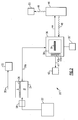
- FIG 1 illustrates selected portions of an example recycling system 20 for recycling spent glycol (e.g., ethylene glycol, propylene glycol, etc.).
- the recycling system 20 receives spent glycol that is mixed with other substances, such as water and biomaterials, and separates the glycol from the other substances.
- the recycling system 20 provides numerous benefits, including recovering relatively pure glycol and using the other substances to produce hydrogen fuel and useful heat.
- the recycling system 20 includes a reservoir 22 for storing spent glycol that is mixed with the other substances.
- the reservoir 22 is an airport reservoir associated with an aircraft de-icing area of an airport. For example, aircrafts are sprayed in the de-icing area with a de-icing fluid that contains glycol.
- the spent de-icing fluid is collected through a drainage system or the like and stored in the reservoir 22.
- the de-icing fluid may mix with solid debris (leaves, grass, etc.), water, or other substances in the de-icing area or within the drainage system.
- a separator 24 receives the spent de-icing fluid (spent glycol) from the reservoir 22 and separates glycol from water and other compounds.
- the separator 24 uses (but is not limited to) membrane filtration, reverse osmosis, etc. or a combination thereof to separate the glycol.
- the separator 24 includes a membrane 26 that separates a high pressure side, H, from a low pressure side, L.
- a heater 28 associated with the separator 24 heats the spent glycol to a temperature that is suitable to vaporize the glycol.
- the vaporized glycol and other substances enter the separator 24 on the high pressure side H.
- the low pressure side L contains a lower concentration of glycol than the high pressure side H with the vaporized glycol.
- the difference in glycol partial pressure causes the vaporized glycol to diffuse from the high pressure side H through the membrane 26 to the low pressure side L, thereby physically separating at least some of the glycol from the other substances.
- separated glycol is relatively pure (i.e. 100% glycol).
- a portion of the other substances also diffuses across the membrane such that the separated glycol is less than 100% pure.
- the concentration or purity of the glycol in the first effluent stream is higher than in the second effluent stream.
- the heater 28 is not used or only heats the glycol and other substances to a temperature below the vaporization temperature of the glycol.
- high pressure on the high pressure side H drives the glycol through the membrane 26 to separate it from the undesired substances (reverse osmosis).
- the separator 24 can be designed to operate as a vapor filter under the principles of partial pressure or as a liquid separator under the principles of reverse osmosis.
- the separator 24 discharges the separated glycol in a first effluent stream 30a and the remaining material in a second effluent stream 30b.
- the second effluent stream 30b includes water, solid biomaterials, and residual glycol.
- the first effluent stream 30a flows to a storage reservoir 32 and the second effluent stream 30b flows to a thermal distiller 34.
- the thermal distiller 34 removes at least a portion of the residual glycol from the second effluent stream 30b using heat.
- a renewable energy source 35 such as a solar thermal energy source, wind energy source coupled to an electric heater or biomass combustion energy source, generates the heat.
- a conventional non-renewable energy source is used.
- the thermal distiller 34 employs fractionation to separate the residual glycol from the second effluent stream 30b and discharges the separated glycol in a third effluent stream 30c to the storage reservoir. The thermal distiller 34 thereby provides the advantage of recovering a greater amount of glycol.
- the second effluent stream 30b which includes the other substances, water and some residual glycol that was not removed by the thermal distiller 34, continues on to a catalytic reactor 36.
- the storage reservoir 32 and effluent streams 30a and 30c contain a glycol mixture that is approximately equal to the solution composition commonly used for aircraft deicing fluids.
- a water selective membrane device 37 (shown in phantom) is located within the second effluent stream 30b either before or after the thermal distiller 34 to remove excess water from the second effluent stream 30b. This provides the benefit of controlling the amount of water in the second effluent stream 30b going to the catalytic reactor 36.
- the catalytic reactor 36 includes a heating chamber 38 having a catalyst 39 that, with heat, chemically reacts the other substances and any remaining residual glycol.
- a renewable energy source 35' such as a solar thermal energy source, wind energy source coupled to an electric heater or biomass combustion energy source, generates the heat.
- a conventional non-renewable energy source is used.
- the catalyst 39 includes a heterogeneous catalyst, such as platinum, iridium, palladium, rhodium, ruthenium, cobalt, nickel, gold or mixtures thereof and a support that is effectively insoluble in the liquid glycol containing liquid.
- the catalyst 39 may also contain activity or selectivity modifiers like tin.
- activity or selectivity modifiers like tin.
- the catalyst 39 and heat cause the reaction of the residual glycol and other substances with water to form a mixture of hydrogen, carbon dioxide, and carbon monoxide, along with, depending on the catalyst 39 chosen, the reaction conditions, and the impurities present, light alkanes such as methane.
- the catalytic reactor 36 includes first and second separation membranes 40a and 40b for facilitating separation of the mixture of hydrogen, carbon monoxide, and carbon dioxide.
- the first separation membrane 40a is a membrane that is suitable for separating hydrogen out of the mixture and the optional second membrane 40b is suitable for separating carbon dioxide out of the mixture.
- the membranes 40a and 40b provide the benefit of producing relatively pure hydrogen that can be stored or used to power vehicles.
- the catalytic reactor 36 discharges the hydrogen in a hydrogen stream 41 into a storage reservoir 42 and discharges a remainder stream 44 into a burner 46.
- the burner 46 combusts the remainder stream 44 to produce heat 48.
- the burner 46 discharges the heat 48 to the catalytic reactor 36, a device 50 that converts the heat to electricity (such as a thermoelectric generator, Rankine engine, Stirling engine etc.) and/or cooling (such as am absorption chiller, adsorption chiller etc.) and/or heating (such as a heat exchanger).
- the heat 48 discharged to the catalytic reactor 36 facilitates chemical reaction between the catalyst 39, the other substances, and residual glycol in the second effluent stream 30b.
- the thermoelectric generator or a Rankine engine or a Stirling engine uses the heat 48 to generate electricity.
- a thermally driven cooling system such as an absorption chiller, adsorption chiller, or desiccant cooler converts the residual thermal energy to useful cooling.
- a heat exchanger uses the heat 48 to change the temperature of a heat transfer fluid and this medium can be used to provide supplemental process heat as needed.
- FIG 2 illustrates a modified embodiment of a recycling system 20'.
- the recycling system 20' is similar to the recycling system 20 shown in Figure 1 except that the recycling system 20' does not include the thermal distiller 34.
- the second effluent stream 30b flows directly into the catalytic reactor 36 without removal of any of the residual glycol.
- any residual glycol in the second effluent stream 30b is converted to hydrogen and heat instead of being separated by the thermal distiller 34 as in the previous embodiment.
- the recycling system 20' thereby provides the benefit of recovering glycol, producing hydrogen and usable heat as in the first example, but without fiscal expenses associated with the thermal distiller 34.
Landscapes
- Chemical & Material Sciences (AREA)
- Organic Chemistry (AREA)
- Chemical Kinetics & Catalysis (AREA)
- Inorganic Chemistry (AREA)
- Engineering & Computer Science (AREA)
- Combustion & Propulsion (AREA)
- Physics & Mathematics (AREA)
- Health & Medical Sciences (AREA)
- General Health & Medical Sciences (AREA)
- Thermal Sciences (AREA)
- Electromagnetism (AREA)
- Toxicology (AREA)
- Separation Using Semi-Permeable Membranes (AREA)
- Organic Low-Molecular-Weight Compounds And Preparation Thereof (AREA)
Abstract
The system can be used in an airport for glycol recycling after de-icing aircrafts.
Description
- This invention relates to recycling and, more particularly, to recycling glycol that is mixed with various other types of substances.
- Glycol is well known and used in a variety of different applications. For example, glycol has a relatively low freezing point (~65°C), which makes it attractive for use as an anti-freezing fluid in vehicles and other systems. One particular use of anti-freezing fluids occurs at airports for de-icing aircrafts before take-off. Typically, an aircraft is sprayed with a de-icing fluid that contains glycol to eliminate ice accumulation and prevent freezing of water on the aircraft. Spent glycol is then either released into the environment or collected within a collection system. Due to environmental concerns, the glycol is preferably collected rather than released.
- Typically, the spent glycol is polluted with water, fumes from the aircraft, solid debris in the collection system such as leaves, grass, etc., and other substances. The spent glycol is not reused in this polluted state. Typically, the airport pays a fee to dispose of it. However, some airports employ a system to recover a portion of the glycol. For example, the spent glycol is collected in a reservoir wherein the undesired substances, which are generally lighter than the glycol, float on top of the glycol. The top is then ignited to bum off the undesired substances (often referred to as "flashing") to produce purer glycol. One drawback to flashing is that it is difficult to obtain highly pure glycol. Other recovery systems include aerobic digesters and distillation columns, however, these systems are prone to leaking, employ relatively expensive equipment, and can be relatively expensive to operate. Additionally, even if the glycol is recovered using any of the above systems, no use is made of the substances that are mixed with the glycol.
- Accordingly, there is a need for a recycle system for recovering a spent substance such as glycol and also recovering or using the other substances mixed with the spent substance. This invention addresses those needs while avoiding the shortcomings and drawbacks of the prior art.
- A fluid recycling system according to the invention includes a separator for physically separating glycol from at least a portion of other substances mixed with the glycol. The separator discharges a first effluent stream having glycol and a second effluent stream having the other substances and residual glycol. A catalytic reactor receives the second effluent stream and chemically reacts the other substances and residual glycol to produce a hydrogen stream and a remainder stream.
- In another aspect, the fluid recycling system includes a separator for physically separating glycol from other substances mixed with the glycol. The separator discharges a first effluent stream having glycol and a second effluent stream having undesired substances and residual glycol. A catalytic reactor having a heating chamber and a catalyst within the heating chamber receives the second effluent stream and chemically reacts the other substances and residual glycol to produce a hydrogen stream and a remainder stream. A thermal distiller between the separator and the catalytic reactor receives the second effluent stream and removes at least a portion of the residual glycol from the second effluent stream. Optionally excess water from the second effluent stream is removed before or after the thermal distiller by means of a water selective membrane. A burner receives the remainder stream from the catalytic reactor and combusts the remainder stream to produce usable heat.
- An example method of recycling includes the steps of separating glycol from other substances mixed with the glycol to produce a first effluent stream having glycol and a second effluent stream having the other substances and residual glycol. The other substances and residual glycol are then chemically reacted with a catalyst to produce a hydrogen stream and a remainder stream.
- The various features and advantages of this invention will become apparent to those skilled in the art from the following detailed description of the currently preferred embodiment. The drawings that accompany the detailed description can be briefly described as follows.
- Figure 1 illustrates an example recycling system for recycling a spent substance such as glycol.
- Figure 2 illustrates a modified example recycling system for recycling a spent substance.
- Figure 1 illustrates selected portions of an
example recycling system 20 for recycling spent glycol (e.g., ethylene glycol, propylene glycol, etc.). As will be described, therecycling system 20 receives spent glycol that is mixed with other substances, such as water and biomaterials, and separates the glycol from the other substances. Therecycling system 20 provides numerous benefits, including recovering relatively pure glycol and using the other substances to produce hydrogen fuel and useful heat. - In the illustrated example, the
recycling system 20 includes areservoir 22 for storing spent glycol that is mixed with the other substances. In one example, thereservoir 22 is an airport reservoir associated with an aircraft de-icing area of an airport. For example, aircrafts are sprayed in the de-icing area with a de-icing fluid that contains glycol. The spent de-icing fluid is collected through a drainage system or the like and stored in thereservoir 22. During the de-icing process, the de-icing fluid may mix with solid debris (leaves, grass, etc.), water, or other substances in the de-icing area or within the drainage system. - A
separator 24 receives the spent de-icing fluid (spent glycol) from thereservoir 22 and separates glycol from water and other compounds. For example, theseparator 24 uses (but is not limited to) membrane filtration, reverse osmosis, etc. or a combination thereof to separate the glycol. - In the disclosed example, the
separator 24 includes amembrane 26 that separates a high pressure side, H, from a low pressure side, L. In the illustrated example, aheater 28 associated with theseparator 24 heats the spent glycol to a temperature that is suitable to vaporize the glycol. The vaporized glycol and other substances enter theseparator 24 on the high pressure side H. In this example, the low pressure side L contains a lower concentration of glycol than the high pressure side H with the vaporized glycol. The difference in glycol partial pressure causes the vaporized glycol to diffuse from the high pressure side H through themembrane 26 to the low pressure side L, thereby physically separating at least some of the glycol from the other substances. In one example, separated glycol is relatively pure (i.e. 100% glycol). In other examples, a portion of the other substances also diffuses across the membrane such that the separated glycol is less than 100% pure. In any case, the concentration or purity of the glycol in the first effluent stream is higher than in the second effluent stream. - Alternatively, the
heater 28 is not used or only heats the glycol and other substances to a temperature below the vaporization temperature of the glycol. In this example, high pressure on the high pressure side H drives the glycol through themembrane 26 to separate it from the undesired substances (reverse osmosis). Thus, theseparator 24 can be designed to operate as a vapor filter under the principles of partial pressure or as a liquid separator under the principles of reverse osmosis. - The
separator 24 discharges the separated glycol in afirst effluent stream 30a and the remaining material in a secondeffluent stream 30b. For example, thesecond effluent stream 30b includes water, solid biomaterials, and residual glycol. In this example, thefirst effluent stream 30a flows to astorage reservoir 32 and thesecond effluent stream 30b flows to a thermal distiller 34. - The thermal distiller 34 removes at least a portion of the residual glycol from the
second effluent stream 30b using heat. In the disclosed example, arenewable energy source 35, such as a solar thermal energy source, wind energy source coupled to an electric heater or biomass combustion energy source, generates the heat. Alternatively, a conventional non-renewable energy source is used. The thermal distiller 34 employs fractionation to separate the residual glycol from thesecond effluent stream 30b and discharges the separated glycol in athird effluent stream 30c to the storage reservoir. The thermal distiller 34 thereby provides the advantage of recovering a greater amount of glycol. Thesecond effluent stream 30b, which includes the other substances, water and some residual glycol that was not removed by the thermal distiller 34, continues on to acatalytic reactor 36. In this example, thestorage reservoir 32 andeffluent streams - Optionally a water selective membrane device 37 (shown in phantom) is located within the
second effluent stream 30b either before or after the thermal distiller 34 to remove excess water from thesecond effluent stream 30b. This provides the benefit of controlling the amount of water in thesecond effluent stream 30b going to thecatalytic reactor 36. - The
catalytic reactor 36 includes aheating chamber 38 having acatalyst 39 that, with heat, chemically reacts the other substances and any remaining residual glycol. In this example, similar to the thermal distiller, a renewable energy source 35', such as a solar thermal energy source, wind energy source coupled to an electric heater or biomass combustion energy source, generates the heat. Alternatively, a conventional non-renewable energy source is used. - In one example, the
catalyst 39 includes a heterogeneous catalyst, such as platinum, iridium, palladium, rhodium, ruthenium, cobalt, nickel, gold or mixtures thereof and a support that is effectively insoluble in the liquid glycol containing liquid. Thecatalyst 39 may also contain activity or selectivity modifiers like tin. One of ordinary skill in the art who has the benefit of this disclosure will recognize other types of catalysts that can be used to suit their particular needs. Thecatalyst 39 and heat cause the reaction of the residual glycol and other substances with water to form a mixture of hydrogen, carbon dioxide, and carbon monoxide, along with, depending on thecatalyst 39 chosen, the reaction conditions, and the impurities present, light alkanes such as methane. Depending on the composition of the other substances in the spent glycol, there may also be other types of molecules in the mixture. - Optionally, the
catalytic reactor 36 includes first andsecond separation membranes first separation membrane 40a is a membrane that is suitable for separating hydrogen out of the mixture and the optionalsecond membrane 40b is suitable for separating carbon dioxide out of the mixture. Given this description, one of ordinary skill in the art will be able to select suitable membranes for separating the mixture in a desirable manner. Thus, themembranes catalytic reactor 36 discharges the hydrogen in ahydrogen stream 41 into astorage reservoir 42 and discharges aremainder stream 44 into aburner 46. - In the disclosed example, the
burner 46 combusts theremainder stream 44 to produceheat 48. In one example, theburner 46 discharges theheat 48 to thecatalytic reactor 36, adevice 50 that converts the heat to electricity (such as a thermoelectric generator, Rankine engine, Stirling engine etc.) and/or cooling (such as am absorption chiller, adsorption chiller etc.) and/or heating (such as a heat exchanger). Theheat 48 discharged to thecatalytic reactor 36 facilitates chemical reaction between thecatalyst 39, the other substances, and residual glycol in thesecond effluent stream 30b. In one example, the thermoelectric generator or a Rankine engine or a Stirling engine uses theheat 48 to generate electricity. In another example, a thermally driven cooling system such as an absorption chiller, adsorption chiller, or desiccant cooler converts the residual thermal energy to useful cooling. In yet another example, a heat exchanger uses theheat 48 to change the temperature of a heat transfer fluid and this medium can be used to provide supplemental process heat as needed. - Figure 2 illustrates a modified embodiment of a recycling system 20'. In this example, like reference numbers are used to describe like components. The recycling system 20' is similar to the
recycling system 20 shown in Figure 1 except that the recycling system 20' does not include the thermal distiller 34. In this embodiment, thesecond effluent stream 30b flows directly into thecatalytic reactor 36 without removal of any of the residual glycol. Thus, any residual glycol in thesecond effluent stream 30b is converted to hydrogen and heat instead of being separated by the thermal distiller 34 as in the previous embodiment. The recycling system 20' thereby provides the benefit of recovering glycol, producing hydrogen and usable heat as in the first example, but without fiscal expenses associated with the thermal distiller 34. - Although a preferred embodiment of this invention has been disclosed, a worker of ordinary skill in this art would recognize that certain modifications would come within the scope of this invention. For that reason, the following claims should be studied to determine the true scope and content of this invention.
Claims (24)
- A fluid recycling system (20) comprising:a separator (24) for physically separating glycol from at least a portion of other substances mixed with the glycol to produce a first effluent stream (30a) having separated glycol and a second effluent stream 30(b) having the other substances and residual glycol; anda catalytic reactor (36) for receiving the second effluent stream and chemically reacting the other substances and residual glycol to produce a hydrogen stream (41) and a remainder stream.
- The fluid recycling system as recited in claim 1, further comprising a renewable energy source (35') that utilizes one of a solar thermal energy source, wind energy source coupled to an electric heater, or biomass combustion energy source, to provide heat to the catalytic reactor (36).
- The fluid recycling system as recited in claim 1 or 2, further comprising a thermal distiller (34) between the separator (24) and the catalytic reactor (36), the thermal distiller receiving the second effluent stream (30b) and removing at least a portion of the residual glycol from the second effluent stream.
- The fluid recycling system as recited in claim 3, further comprising a renewable energy source (35) that utilizes one of a solar thermal energy source, wind energy source coupled to an electric heater, or biomass combustion energy source, to provide heat to the thermal distiller (34).
- The fluid recycling system as recited in claim 1, 2, 3 or 4, further comprising a water selective membrane device (37) between the separator and the catalytic reactor for removing water from the second effluent stream.
- The fluid recycling system as recited in any preceding claim, wherein the separator (24) includes a membrane (26).
- The fluid recycling system as recited in claim 6, wherein the separator includes a low pressure side (L) and a high pressure side (H) separated by the membrane (26) such that the glycol moves through the membrane from the high pressure side to the low pressure side to separate the glycol from the other substances.
- The fluid recycling system as recited in claim 7, further comprising a heater (28) to heat and vaporize at least the glycol such that the vaporized glycol moves through the membrane from the high pressure side to the low pressure side.
- The fluid recycling system as recited in any preceding claim, wherein the catalytic reactor (36) includes a heating chamber (38) and a heterogeneous catalyst (39) within the heating chamber.
- The fluid recycling system as recited in any preceding claim, further comprising a burner (46) for receiving the remainder stream from the catalytic reactor and combusting the remainder stream (44) to produce heat.
- The fluid recycling system as recited in claim 10, further comprising a heat exchanger (50) for receiving the heat from the burner.
- The fluid recycling system as recited in claim 10 or 11, further comprising a thermoelectric power generator (50) for receiving the heat from the burner.
- The fluid recycling system as recited in claim 10, 11 or 12, further comprising at least one (50) of a Rankine engine, a Stirling engine, an absorption chiller, an adsorption chiller, or a desiccant cooler for receiving the heat from the burner.
- The fluid recycling system as recited in any preceding claim, further comprising a storage reservoir (42) for storing hydrogen from the hydrogen stream.
- The fluid recycling system as recited in any preceding claim, further comprising an airport glycol collection reservoir (22) for supplying glycol mixed with the other substances to the separator.
- A fluid recycling system (20) comprising:a separator (24) having a membrane (26) for physically separating glycol from other substances mixed with the glycol to produce a first effluent stream (30a) having separated glycol and a second effluent stream (30b) having the other substances and residual glycol;a catalytic reactor (36) having a heating chamber (38) and a catalyst (39) within the heating chamber for receiving the second effluent stream and chemically reacting the other substances and residual glycol to produce a hydrogen stream (41) and a remainder stream (44);a thermal distiller (34) between the separator (24) and the catalytic reactor (36) for receiving the second effluent stream (30b) and removing at least a portion of the residual glycol from the second effluent stream; anda burner (46) for receiving the remainder stream (44) from the catalytic reactor and combusting the remainder stream to produce heat.
- The fluid recycling system as recited in claim 16 further comprising a heat exchanger (50) for receiving the heat from the burner (46), and a heater (28) associated with the separator (24) to heat and vaporize at least the glycol such that the vaporized glycol moves through the membrane from a high pressure side to a low pressure side.
- A method of recycling, comprising the steps of:(a) separating glycol from other substances mixed with the glycol to produce a first effluent stream having separated glycol and a second effluent stream having the other substances and residual glycol; and(b) chemically reacting the other substances and residual glycol to produce a hydrogen stream and a remainder stream.
- The method as recited in claim 18, including the step of thermally distilling the second effluent stream to remove at least a portion of the residual glycol.
- The method as recited in claim 18 or 19, wherein step (a) includes producing a high pressure on one side of a membrane to move the glycol through the membrane to separate the glycol from at least a portion of the other substances.
- The method as recited in claim 20, including heating and vaporizing at least the glycol.
- The method as recited in claim 18, 19, 20 or 21, including the step of combusting the remainder stream to produce heat.
- The method as recited in claim 22, including the step of changing the temperature of a fluid with the heat.
- The method as recited in claim 22 or 23, including the step of generating electricity using the heat.
Applications Claiming Priority (1)
| Application Number | Priority Date | Filing Date | Title |
|---|---|---|---|
| US11/505,079 US7713319B2 (en) | 2006-08-16 | 2006-08-16 | Glycol recycle system |
Publications (3)
| Publication Number | Publication Date |
|---|---|
| EP1889658A2 true EP1889658A2 (en) | 2008-02-20 |
| EP1889658A3 EP1889658A3 (en) | 2008-02-27 |
| EP1889658B1 EP1889658B1 (en) | 2011-02-02 |
Family
ID=38669275
Family Applications (1)
| Application Number | Title | Priority Date | Filing Date |
|---|---|---|---|
| EP07253239A Not-in-force EP1889658B1 (en) | 2006-08-16 | 2007-08-16 | Glycol recycle system |
Country Status (5)
| Country | Link |
|---|---|
| US (1) | US7713319B2 (en) |
| EP (1) | EP1889658B1 (en) |
| BR (1) | BRPI0705737A (en) |
| CA (1) | CA2597314C (en) |
| DE (1) | DE602007012329D1 (en) |
Cited By (5)
| Publication number | Priority date | Publication date | Assignee | Title |
|---|---|---|---|---|
| WO2009097857A1 (en) * | 2008-02-05 | 2009-08-13 | Union Engineering | Method for recovery of heat from a carbon dioxide recovery process |
| DE102008063094A1 (en) | 2008-12-24 | 2010-07-01 | Clariant International Limited | Process for processing glycol-containing aircraft deicing compositions |
| DE102008063095A1 (en) | 2008-12-24 | 2010-07-01 | Clariant International Limited | Process for the treatment of glycol-containing aircraft emptying agents |
| WO2014198379A1 (en) | 2013-06-13 | 2014-12-18 | Clariant International Ltd | Method for reprocessing aircraft de-icing agents comprising glycol |
| CN112354506A (en) * | 2020-12-02 | 2021-02-12 | 内蒙古农业大学 | Nano-emulsion preparation device of composite sterilant |
Families Citing this family (5)
| Publication number | Priority date | Publication date | Assignee | Title |
|---|---|---|---|---|
| US8252149B2 (en) | 2007-07-24 | 2012-08-28 | Brad Michael Malatesta | Method of cleaning and recycling glycol-tainted water from de-icing operations at airports |
| WO2013110035A1 (en) * | 2012-01-20 | 2013-07-25 | Hydration Systems, Llc | System and method for secondary uses of glycol and water after deicing |
| US10144688B2 (en) * | 2016-03-17 | 2018-12-04 | Aéro Mag 2000 Rrr Inc. | Method and system for recycling spent ethylene glycol from recovered aircraft de-icing solutions |
| JP6814823B2 (en) | 2016-03-16 | 2021-01-20 | アエロ マグ 2000 エルエルエル インコーポレイテッド | Recycling method and system for used ethylene glycol recovered from aircraft deicing liquid |
| DE102022210662A1 (en) * | 2022-10-10 | 2024-04-11 | Hyundai Motor Company | Hydrogen tank and method for operating a hydrogen tank |
Family Cites Families (14)
| Publication number | Priority date | Publication date | Assignee | Title |
|---|---|---|---|---|
| US4225394A (en) * | 1976-04-14 | 1980-09-30 | Ppg Industries, Inc. | Reclamation of spent glycol by treatment with alkali metal hydroxide and distillation |
| US5236558A (en) * | 1982-09-23 | 1993-08-17 | Allied-Signal Inc. | Method to recycle spent ethylene glycol |
| US5194159A (en) * | 1989-12-27 | 1993-03-16 | Union Carbide Chemicals & Plastics Technology Corporation | Treatment of lower glycol-containing operative fluids |
| US5104068A (en) | 1990-08-10 | 1992-04-14 | Krilla Ronald A | Apparatus and method for de-icing and anti-icing (and/or cleaning and rinsing) aircraft |
| DE4130661C1 (en) * | 1991-09-14 | 1993-05-19 | Dornier Gmbh, 7990 Friedrichshafen, De | |
| DE4326345A1 (en) * | 1993-08-05 | 1995-02-09 | Hoechst Ag | Process for the reprocessing of used glycolic aircraft de-icing agents |
| US5462655A (en) | 1993-09-20 | 1995-10-31 | Ladd; Michael | Vehicle containment mat with vacuum recovery and recycle means |
| US5552023A (en) * | 1993-12-15 | 1996-09-03 | Alliedsignal Inc. | Recovery of spent deicing fluid |
| US5785857A (en) * | 1996-04-30 | 1998-07-28 | Mobile Process Technology, Inc. | Mobile process for the recovery of spent heat transfer fluids |
| US5997594A (en) | 1996-10-30 | 1999-12-07 | Northwest Power Systems, Llc | Steam reformer with internal hydrogen purification |
| US6221117B1 (en) * | 1996-10-30 | 2001-04-24 | Idatech, Llc | Hydrogen producing fuel processing system |
| US5932105A (en) * | 1997-10-01 | 1999-08-03 | Mobile Process Technology, Co. | Method of polyester manufacturing using crossflow membrane filtration |
| US6789288B2 (en) * | 2002-10-25 | 2004-09-14 | Membrane Technology And Research, Inc. | Natural gas dehydration process and apparatus |
| US20040079491A1 (en) * | 2002-10-28 | 2004-04-29 | Harris James Jeffrey | Evaporative process for the reconstitution of glycol bearing deicing fluids |
-
2006
- 2006-08-16 US US11/505,079 patent/US7713319B2/en not_active Expired - Fee Related
-
2007
- 2007-08-16 DE DE602007012329T patent/DE602007012329D1/en active Active
- 2007-08-16 BR BRPI0705737-7A patent/BRPI0705737A/en not_active IP Right Cessation
- 2007-08-16 EP EP07253239A patent/EP1889658B1/en not_active Not-in-force
- 2007-08-16 CA CA2597314A patent/CA2597314C/en not_active Expired - Fee Related
Cited By (10)
| Publication number | Priority date | Publication date | Assignee | Title |
|---|---|---|---|---|
| WO2009097857A1 (en) * | 2008-02-05 | 2009-08-13 | Union Engineering | Method for recovery of heat from a carbon dioxide recovery process |
| DE102008063094A1 (en) | 2008-12-24 | 2010-07-01 | Clariant International Limited | Process for processing glycol-containing aircraft deicing compositions |
| DE102008063095A1 (en) | 2008-12-24 | 2010-07-01 | Clariant International Limited | Process for the treatment of glycol-containing aircraft emptying agents |
| WO2010072312A3 (en) * | 2008-12-24 | 2011-02-24 | Clariant Finance (Bvi) Limited | Method for reprocessing aircraft de-icing agents comprising glycol |
| WO2010072311A3 (en) * | 2008-12-24 | 2011-02-24 | Clariant Finance (Bvi) Limited | Process for workup of glycol-containing aircraft deicers |
| WO2014198379A1 (en) | 2013-06-13 | 2014-12-18 | Clariant International Ltd | Method for reprocessing aircraft de-icing agents comprising glycol |
| DE102013009949A1 (en) | 2013-06-13 | 2014-12-18 | Clariant International Ltd. | Process for processing glycol-containing aircraft deicing compositions |
| US9539521B2 (en) | 2013-06-13 | 2017-01-10 | Clariant International Ltd. | Method for reprocessing aircraft de-icing agents comprising glycol |
| CN112354506A (en) * | 2020-12-02 | 2021-02-12 | 内蒙古农业大学 | Nano-emulsion preparation device of composite sterilant |
| CN112354506B (en) * | 2020-12-02 | 2022-04-19 | 内蒙古农业大学 | Nano-emulsion preparation device of composite sterilant |
Also Published As
| Publication number | Publication date |
|---|---|
| US20080044325A1 (en) | 2008-02-21 |
| DE602007012329D1 (en) | 2011-03-17 |
| EP1889658B1 (en) | 2011-02-02 |
| CA2597314A1 (en) | 2008-02-16 |
| EP1889658A3 (en) | 2008-02-27 |
| BRPI0705737A (en) | 2008-06-03 |
| CA2597314C (en) | 2010-11-16 |
| US7713319B2 (en) | 2010-05-11 |
Similar Documents
| Publication | Publication Date | Title |
|---|---|---|
| EP1889658B1 (en) | Glycol recycle system | |
| AU2021451457B2 (en) | Ammonia cracking for green hydrogen with nox removal | |
| US8865954B2 (en) | Production of diesel fuel from biorenewable feedstocks with selective separation of converted oxygen | |
| JP6983236B2 (en) | How to provide hydrogen gas | |
| CN110582336B (en) | Systems for the separation of dissolved gases by distillation and stripping | |
| US6117404A (en) | Apparatus and process for recovering basic amine compounds in a process for removing carbon dioxide | |
| US20180216010A1 (en) | Process for producing diesel fuel and jet fuel from biorenewable feedstocks | |
| EP2311546B1 (en) | Apparatus for recovering carbon dioxide from flue gas | |
| JP2004079262A (en) | Hydrogen-supply system and mobile hydrogen production equipment | |
| EP2207612A1 (en) | Method of producing synthetic fuels and organic chemicals from atmospheric carbon dioxide | |
| JP2012236847A (en) | Efficient and selective chemical recycling of carbon dioxide to methanol, dimethyl ether and derived products | |
| CN101267882B (en) | Device for the generation of hydrogen gas by dehydrogenation of hydrocarbon fuels | |
| MX2015004354A (en) | PRODUCTION OF FRACTIONATED AND IMPROVED FUELS FROM BIOMASS. | |
| EP3045425B1 (en) | Manufacturing device and manufacturing method for hydrogen and synthetic natural gas | |
| US6794417B2 (en) | System and method for treatment of water and disposal of contaminants produced by converting lighter hydrocarbons into heavier hydrocarbon | |
| CA3155106C (en) | System and method for the production of synthetic fuels without fresh water | |
| EP1236679A2 (en) | Apparatus for generating hydrogen | |
| ES2720727T3 (en) | Process and apparatus for producing hydrocarbons | |
| EA019378B1 (en) | System for separating catalyst | |
| CN102741205A (en) | Converting co2, to an alcohol | |
| US20120125012A1 (en) | Processes and systems for discharging amine byproducts formed in an amine-based solvent | |
| RU2430141C2 (en) | Liquid fuel synthesis system | |
| JP2009040862A (en) | Purification method of coal gasification gas and apparatus therefor | |
| US20160046869A1 (en) | Hydrocarbon-producing apparatus and hydro-carbon- producing method | |
| US20110220848A1 (en) | Gasification of crude glycerol |
Legal Events
| Date | Code | Title | Description |
|---|---|---|---|
| PUAI | Public reference made under article 153(3) epc to a published international application that has entered the european phase |
Free format text: ORIGINAL CODE: 0009012 |
|
| PUAL | Search report despatched |
Free format text: ORIGINAL CODE: 0009013 |
|
| AK | Designated contracting states |
Kind code of ref document: A2 Designated state(s): AT BE BG CH CY CZ DE DK EE ES FI FR GB GR HU IE IS IT LI LT LU LV MC MT NL PL PT RO SE SI SK TR |
|
| AX | Request for extension of the european patent |
Extension state: AL BA HR MK YU |
|
| AK | Designated contracting states |
Kind code of ref document: A3 Designated state(s): AT BE BG CH CY CZ DE DK EE ES FI FR GB GR HU IE IS IT LI LT LU LV MC MT NL PL PT RO SE SI SK TR |
|
| AX | Request for extension of the european patent |
Extension state: AL BA HR MK YU |
|
| 17P | Request for examination filed |
Effective date: 20080425 |
|
| 17Q | First examination report despatched |
Effective date: 20080602 |
|
| AKX | Designation fees paid |
Designated state(s): DE FR GB |
|
| GRAP | Despatch of communication of intention to grant a patent |
Free format text: ORIGINAL CODE: EPIDOSNIGR1 |
|
| GRAS | Grant fee paid |
Free format text: ORIGINAL CODE: EPIDOSNIGR3 |
|
| GRAA | (expected) grant |
Free format text: ORIGINAL CODE: 0009210 |
|
| AK | Designated contracting states |
Kind code of ref document: B1 Designated state(s): DE FR GB |
|
| REG | Reference to a national code |
Ref country code: GB Ref legal event code: FG4D |
|
| REF | Corresponds to: |
Ref document number: 602007012329 Country of ref document: DE Date of ref document: 20110317 Kind code of ref document: P |
|
| REG | Reference to a national code |
Ref country code: DE Ref legal event code: R096 Ref document number: 602007012329 Country of ref document: DE Effective date: 20110317 |
|
| PLBE | No opposition filed within time limit |
Free format text: ORIGINAL CODE: 0009261 |
|
| STAA | Information on the status of an ep patent application or granted ep patent |
Free format text: STATUS: NO OPPOSITION FILED WITHIN TIME LIMIT |
|
| 26N | No opposition filed |
Effective date: 20111103 |
|
| REG | Reference to a national code |
Ref country code: DE Ref legal event code: R097 Ref document number: 602007012329 Country of ref document: DE Effective date: 20111103 |
|
| PGFP | Annual fee paid to national office [announced via postgrant information from national office to epo] |
Ref country code: DE Payment date: 20130814 Year of fee payment: 7 |
|
| PGFP | Annual fee paid to national office [announced via postgrant information from national office to epo] |
Ref country code: GB Payment date: 20130814 Year of fee payment: 7 Ref country code: FR Payment date: 20130808 Year of fee payment: 7 |
|
| REG | Reference to a national code |
Ref country code: DE Ref legal event code: R119 Ref document number: 602007012329 Country of ref document: DE |
|
| GBPC | Gb: european patent ceased through non-payment of renewal fee |
Effective date: 20140816 |
|
| REG | Reference to a national code |
Ref country code: DE Ref legal event code: R119 Ref document number: 602007012329 Country of ref document: DE Effective date: 20150303 |
|
| REG | Reference to a national code |
Ref country code: FR Ref legal event code: ST Effective date: 20150430 |
|
| PG25 | Lapsed in a contracting state [announced via postgrant information from national office to epo] |
Ref country code: GB Free format text: LAPSE BECAUSE OF NON-PAYMENT OF DUE FEES Effective date: 20140816 Ref country code: DE Free format text: LAPSE BECAUSE OF NON-PAYMENT OF DUE FEES Effective date: 20150303 |
|
| PG25 | Lapsed in a contracting state [announced via postgrant information from national office to epo] |
Ref country code: FR Free format text: LAPSE BECAUSE OF NON-PAYMENT OF DUE FEES Effective date: 20140901 |