EP1888883B1 - Lng-based power and regasification system - Google Patents
Lng-based power and regasification system Download PDFInfo
- Publication number
- EP1888883B1 EP1888883B1 EP06728251A EP06728251A EP1888883B1 EP 1888883 B1 EP1888883 B1 EP 1888883B1 EP 06728251 A EP06728251 A EP 06728251A EP 06728251 A EP06728251 A EP 06728251A EP 1888883 B1 EP1888883 B1 EP 1888883B1
- Authority
- EP
- European Patent Office
- Prior art keywords
- lng
- condenser
- turbine
- working fluid
- heater
- Prior art date
- Legal status (The legal status is an assumption and is not a legal conclusion. Google has not performed a legal analysis and makes no representation as to the accuracy of the status listed.)
- Expired - Lifetime
Links
Images











Classifications
-
- F—MECHANICAL ENGINEERING; LIGHTING; HEATING; WEAPONS; BLASTING
- F01—MACHINES OR ENGINES IN GENERAL; ENGINE PLANTS IN GENERAL; STEAM ENGINES
- F01K—STEAM ENGINE PLANTS; STEAM ACCUMULATORS; ENGINE PLANTS NOT OTHERWISE PROVIDED FOR; ENGINES USING SPECIAL WORKING FLUIDS OR CYCLES
- F01K27/00—Plants for converting heat or fluid energy into mechanical energy, not otherwise provided for
-
- F—MECHANICAL ENGINEERING; LIGHTING; HEATING; WEAPONS; BLASTING
- F01—MACHINES OR ENGINES IN GENERAL; ENGINE PLANTS IN GENERAL; STEAM ENGINES
- F01K—STEAM ENGINE PLANTS; STEAM ACCUMULATORS; ENGINE PLANTS NOT OTHERWISE PROVIDED FOR; ENGINES USING SPECIAL WORKING FLUIDS OR CYCLES
- F01K25/00—Plants or engines characterised by use of special working fluids, not otherwise provided for; Plants operating in closed cycles and not otherwise provided for
- F01K25/08—Plants or engines characterised by use of special working fluids, not otherwise provided for; Plants operating in closed cycles and not otherwise provided for using special vapours
- F01K25/10—Plants or engines characterised by use of special working fluids, not otherwise provided for; Plants operating in closed cycles and not otherwise provided for using special vapours the vapours being cold, e.g. ammonia, carbon dioxide, ether
-
- F—MECHANICAL ENGINEERING; LIGHTING; HEATING; WEAPONS; BLASTING
- F01—MACHINES OR ENGINES IN GENERAL; ENGINE PLANTS IN GENERAL; STEAM ENGINES
- F01K—STEAM ENGINE PLANTS; STEAM ACCUMULATORS; ENGINE PLANTS NOT OTHERWISE PROVIDED FOR; ENGINES USING SPECIAL WORKING FLUIDS OR CYCLES
- F01K25/00—Plants or engines characterised by use of special working fluids, not otherwise provided for; Plants operating in closed cycles and not otherwise provided for
-
- F—MECHANICAL ENGINEERING; LIGHTING; HEATING; WEAPONS; BLASTING
- F01—MACHINES OR ENGINES IN GENERAL; ENGINE PLANTS IN GENERAL; STEAM ENGINES
- F01K—STEAM ENGINE PLANTS; STEAM ACCUMULATORS; ENGINE PLANTS NOT OTHERWISE PROVIDED FOR; ENGINES USING SPECIAL WORKING FLUIDS OR CYCLES
- F01K25/00—Plants or engines characterised by use of special working fluids, not otherwise provided for; Plants operating in closed cycles and not otherwise provided for
- F01K25/08—Plants or engines characterised by use of special working fluids, not otherwise provided for; Plants operating in closed cycles and not otherwise provided for using special vapours
-
- F—MECHANICAL ENGINEERING; LIGHTING; HEATING; WEAPONS; BLASTING
- F17—STORING OR DISTRIBUTING GASES OR LIQUIDS
- F17C—VESSELS FOR CONTAINING OR STORING COMPRESSED, LIQUEFIED OR SOLIDIFIED GASES; FIXED-CAPACITY GAS-HOLDERS; FILLING VESSELS WITH, OR DISCHARGING FROM VESSELS, COMPRESSED, LIQUEFIED, OR SOLIDIFIED GASES
- F17C2265/00—Effects achieved by gas storage or gas handling
- F17C2265/05—Regasification
Definitions
- the present invention relates to the field of power generation. More particularly, the invention relates to a system which both utilizes liquefied natural gas for power generation and re-gasifies the liquefied natural gas.
- the LNG In the vicinity of the destination port, the LNG is transported to a regasification terminal, whereat it is reheated by heat exchange with sea water or with the exhaust gas of gas turbines and converted into gas.
- Each regasification terminal is usually connected with a distribution network of pipelines so that the regasified natural gas may be transmitted to an end user. While a regasification terminal is efficient in terms of the ability to vaporize the LNG so that it may be transmitted to end users, there is a need for an efficient method for harnessing the cold potential of the LNG as a cold sink for a condenser to generate power.
- the system may further comprises a compressor for compressing regasified LNG and transmitting said compressed regasified LNG along a pipeline to end users.
- the compressor may be coupled to the turbine.
- the regasified LNG may also be transmitted via the line to storage.
- the present invention is a power and regasification system based on liquid natural gas (LNG). While transported LNG, e.g. mostly methane, is vaporized in the prior art at a regasification terminal by being passed through a heat exchanger, wherein sea water or another heat source e.g. the exhaust of a gas turbine heats the LNG above its boiling point, an efficient method for utilizing the cold LNG to produce power is needed.
- LNG liquid natural gas
- sea water or another heat source e.g. the exhaust of a gas turbine heats the LNG above its boiling point
- an efficient method for utilizing the cold LNG to produce power is needed.
- the cold temperature potential of the LNG serves as a cold sink of a power cycle. Electricity or power is generated due to the large temperature differential between the cold LNG and the heat source, e.g. sea water.
- the sea water discharged from vaporizer 20 via line 19 is returned to the ocean.
- turbine 25 i.e. from state C to state D
- power or preferably electricity is produced by generator 28 operated to turbine 25.
- turbine 25 rotates at about 1500 RPM or 1800 RPM.
- LNG in line 32 at an average temperature of approximately -160°C introduced to condenser 30 i.e. at state E
- condenser 30 serves to condense the working fluid exiting turbine 25 (i.e. from state D to state A) corresponding to a liquid phase, so that pump 15 delivers the liquid working fluid to vaporizer 20.
- the LNG lowers the temperature of the working fluid to a considerably low temperature of about -80°C to -120°C, the recoverable energy available by expanding the vaporized working fluid in turbine 25 is relatively high.
- turbine 65 As the vaporized LNG is expanded in turbine 65 from state I to state J, power or preferably electricity is produced by generator 68 coupled to turbine 65. Preferably, turbine 65 rotates at 1500 RPM or 1800 RPM. Since the LNG at state G has a considerably low temperature of -160°C and is subsequently pressurized by pump 55 from state G to state H so that high pressure vapor is produced in vaporizer 60, the energy in the vaporized LNG is relatively high and is utilized via expansion in turbine 65.
- the position of direct contact condenser/heaters 32B' and 32B" can be changed such that the inlet of direct contact condenser/heaters 32B' can receive working fluid condensate exiting intermediate pressure condenser 31B' (see Fig. 7A ) while direct contact condenser/heaters 32B" can receive pressurized working fluid condensate exiting cycle pump 16B" (see Fig. 7B ).
- Fig. 7D shows a still further alternative version of the embodiment described with reference to Fig. 7 wherein rather than using a direct contact condenser/heater, an indirect condenser/heater is used.
- an indirect condenser/heater is used.
- only one cycle pump can be used wherein suitable valves can be used in the intermediate pressure condensate lines.
- power plant system 10C includes, in addition, gas turbine unit 125 the exhaust gas of which providing the heat source for steam turbine system 100.
- gas turbine unit 125 the exhaust gas of which providing the heat source for steam turbine system 100.
- the exhaust gas of gas turbine 124 is supplied to vaporizer 120 for producing steam from water contained therein.
- the steam produced is supplied to steam turbine 105 where it expands and produces power and preferably drives electric generator 110 generating electricity.
- the expanded steam is supplied to steam condenser/vaporizer 120C where steam condensate is produced and cycle pump 115 supplies the steam condensate to vaporizer 120 thus completing the steam turbine cycle.
- Condenser/vaporizer 120C also acts as a vaporizer and vaporizes liquid organic working fluid present therein.
- a closed organic Rankine cycle power system is used.
- Numeral 1OD designates a power plant system including intermediate power cycle system 100D as well as closed organic Rankine cycle power system 86D.
- LNG pump 40D is preferably used for pressurizing the LNG prior to supplying it to condenser 30D to a pressure, e.g. about 80 bar, for producing a pressure for the re-gasified LNG suitable for supply via line 43D to a pipeline for distribution of vaporized LNG to end users.
- the preferred organic working fluid is ethane, ethene or equivalent.
- Expanded organic working fluid vapor exiting organic vapor turbine is supplied to condenser 30D where organic working fluid condensate is produced by pressurized LNG supplied thereto by LNG pump 40D.
- Cycle pump 15D supplies the organic working fluid condensate from condenser 30D to condenser/vaporizer 120D.
- Pressurized LNG is heated in condenser 30D and preferably heater 36D further the pressurized LNG so that regasified LNG is produced for storage or supply via a pipeline for distribution of vaporized LNG to end users. Due to pressurizing of the LNG prior to supplied the LNG to the condenser, it can be advantageous to use a propane/ethane mixture as the organic working fluid of the organic Rankine cycle power system rather than ethane mentioned above.
Landscapes
- Engineering & Computer Science (AREA)
- Chemical & Material Sciences (AREA)
- Combustion & Propulsion (AREA)
- Mechanical Engineering (AREA)
- General Engineering & Computer Science (AREA)
- Engine Equipment That Uses Special Cycles (AREA)
- Filling Or Discharging Of Gas Storage Vessels (AREA)
- Measurement Of Radiation (AREA)
- Radar Systems Or Details Thereof (AREA)
- Processing Of Solid Wastes (AREA)
- Solid-Sorbent Or Filter-Aiding Compositions (AREA)
- Amplifiers (AREA)
Abstract
Description
- The present invention relates to the field of power generation. More particularly, the invention relates to a system which both utilizes liquefied natural gas for power generation and re-gasifies the liquefied natural gas.
- In some regions of the world, the transportation of natural gas through pipelines is uneconomic. The natural gas is therefore cooled to a temperature below its boiling point, e.g. -160°C, until becoming liquid and the liquefied natural gas (LNG) is subsequently stored in tanks. Since the volume of natural gas is considerably less in liquid phase than in gaseous phase, the LNG can be conveniently and economically transported by ship to a destination port.
- In the vicinity of the destination port, the LNG is transported to a regasification terminal, whereat it is reheated by heat exchange with sea water or with the exhaust gas of gas turbines and converted into gas. Each regasification terminal is usually connected with a distribution network of pipelines so that the regasified natural gas may be transmitted to an end user. While a regasification terminal is efficient in terms of the ability to vaporize the LNG so that it may be transmitted to end users, there is a need for an efficient method for harnessing the cold potential of the LNG as a cold sink for a condenser to generate power.
- Use of Rankine cycles for power generation from evaporating LNG are considered in "Design of Rankine Cycles for power generation from evaporating LNG", Maertens, J., International Journal of Refrigeration, 1986, Vol. 9, May. In addition, further power cycles using LNG/LPG (liquefied petroleum gas) are considered in
US Patent No. 6,367,258 . Another power cycle utilizing LNG is considered inUS Patent No: 6,336,316 . More power cycles using LNG are described in "Energy recovery on LNG import terminals ERoS RT project" by Snecma Moteurs, made available at the Gastech 2005, The 21st International Conference & Exhibition for the LNG, LPG and Natural Gas Industries, - 14/17 March, 2005 Bilbao, Spain. - According to
FR-A-2 300 216 - On the other hand, a power cycle including a combined cycle power plant and an organic Rankine cycle power plant using the condenser of the steam turbine as its heat source is disclosed in
US Patent No. 5,687,570 , the disclosure of which is hereby included by reference. - It is an object of the present invention to provide an LNG-based power and regasification system, which utilizes the low temperature of the LNG as a cold sink for the condenser of the power system in order to generate electricity or produce power for direct use.
Other objects and advantages of the invention will become apparent as the description proceeds. - The present invention provides a closed organic Rankine cycle power system and regasification system based on liquefied natural gas (LNG), comprising:
- a) a vaporizer in which liquid working fluid is vaporized, said liquid working fluid being a working fluid liquefied by the LNG;
- b) a turbine for expanding the vaporized working fluid and producing power;
- c) a condenser to which expanded working fluid vapour is supplied, said condenser also being supplied with LNG for receiving heat from said expanded fluid vapour wherein said LNG condenses said expanded working fluid exiting the turbine and whereby the temperature of the LNG increases as it flows through the condenser;
- d) a line for transmitting regasified LNG
characterised by: - e) a condenser/heater for condensing vapors extracted from an intermediate stage of said turbine and heating working fluid condensate supplied to said condenser/heater from said condenser.
- Power is generated due to the large temperature differential between cold LNG, e.g. approximately -160°C, and the heat source of the vaporizer. The heat source of the vaporizer may be sea water at a temperature ranging between approximately 5°C to 20°C or heat such as an exhaust gas discharged from a gas turbine or low pressure steam exiting a condensing steam turbine. The system further comprises a pump for delivering liquid working fluid to the vaporizer.
- The system further comprises a pump for delivering liquid working fluid to the vaporizer.
- The system may further comprises a compressor for compressing regasified LNG and transmitting said compressed regasified LNG along a pipeline to end users. The compressor may be coupled to the turbine. The regasified LNG may also be transmitted via the line to storage.
- According to the invention, the power system is a closed Rankine cycle power system such that the conduit further extends from the outlet of the heat-exchanger means to the inlet of the vaporizer and the heat exchanger means is a condenser by which the LNG condenses the working fluid exhausted from the turbine to a temperature ranging from approximately -100°C to -120°C. The working fluid is preferably organic fluid such as ethane, ethene or methane or equivalents, or a mixture of propane and ethane or equivalents. The temperature of the LNG heated by the turbine exhaust is preferably further increased by means of a heater.
- In another embodiment of the invention, the power system includes a closed cycle power plant and an open cycle power plant wherein in the open cycle power plant the working fluid is LNG, and the heat exchanger means is a heater for re-gasifying the LNG exhausted from the turbine.
- The heat source of the heater may be sea water at a temperature ranging between approximately 5°C to 20°C or waste heat such as an exhaust gas discharged from a gas turbine.
- In the drawings:
-
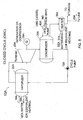
Fig. 1 is a schematic arrangement of a closed cycle power system; -
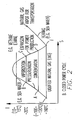
Fig. 2 is a temperature-entropy diagram of the closed cycle power system ofFig. 1 ; -
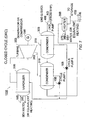
Fig. 3 is a schematic arrangement of an open cycle power system; -
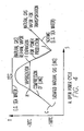
Fig. 4 is a temperature-entropy diagram of the open cycle power system ofFig. 3 . -
Fig. 5 is a schematic arrangement of a further closed cycle power system; -
Fig. 6 is a temperature-entropy diagram of the closed cycle power system ofFig. 5 ; -
Fig. 7 is a schematic arrangement of a two pressure level closed cycle power system; -
Fig. 7A is a schematic arrangement of an alternative version of the two pressure level closed cycle power system shown inFig. 7 in accordance with one embodiment of the invention; -
Fig. 7B is a schematic arrangement of a further alternative version of the two pressure level closed cycle power system shown inFig. 7 in accordance with a further embodiment of the invention; -
Fig. 7C is a schematic arrangement of further alternative versions of the two pressure level closed cycle power system shown inFig. 7 in accordance with a further embodiment of the invention; -
Fig. 7D is a schematic arrangement of a further alternative version o the two pressure level closed cycle power system shown inFig. 7 in accordance with a further embodiment of the invention; -
Fig. 7E is a schematic arrangement of a further alternative version of the two pressure level closed cycle power system shown inFig. 7 in accordance with a further embodiment of the invention; -
Fig. 7F is a schematic arrangement of a further alternative version of a two pressure level open cycle power system; -
Fig. 7G is a schematic arrangement of a further alternative version of the two pressure level open cycle power system shown inFig. 7F ; -
Fig. 7H is a schematic arrangement of a further alternative version of the two pressure level open cycle power system shown inFig. 7F ; -
Fig. 7I is a schematic arrangement of a further alternative version of the two pressure level open cycle power system shown inFig. 7F ; -
Fig. 7J is a schematic arrangement of a further alternative version of the two pressure level open cycle power system shown inFig. 7F ; -
Fig. 7K is a schematic arrangement of a further alternative version of the two pressure level open cycle power system shown inFig. 7F ; -
Fig. 7L is a schematic arrangement of further embodiments of an open cycle power system; -
Fig. 7M is a schematic arrangement of a further embodiment of the present invention including an closed cycle power plant and an open cycle power plant; -
Fig. 8 is a schematic arrangement of a closed cycle power system in accordance with a further embodiment of the invention; and -
Fig. 9 is a schematic arrangement of a closed cycle power system in accordance with a still further embodiment of the invention. Similar reference numerals and symbols refer to similar components. - The present invention is a power and regasification system based on liquid natural gas (LNG). While transported LNG, e.g. mostly methane, is vaporized in the prior art at a regasification terminal by being passed through a heat exchanger, wherein sea water or another heat source e.g. the exhaust of a gas turbine heats the LNG above its boiling point, an efficient method for utilizing the cold LNG to produce power is needed. By employing the power system of the present invention, the cold temperature potential of the LNG serves as a cold sink of a power cycle. Electricity or power is generated due to the large temperature differential between the cold LNG and the heat source, e.g. sea water.
-
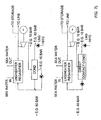
Figs. 1 and2 illustrate one embodiment of the invention, wherein cold LNG serves as the cold sink medium in the condenser of a closed Rankine cycle power plant.Fig. 1 is a schematic arrangement of the power system andFig. 2 is a temperature-entropy diagram of the closed cycle. - The power system of a closed Rankine cycle is generally designated as
numeral 10. Organic fluid such as ethane, ethene or methane or an equivalent, is the preferred working fluid forpower system 10 and circulates throughconduits 8.Pump 15 delivers liquid organic fluid at state A, the temperature of which ranges from about -80°C to -120°C, to vaporizer 20 at state B. Sea water inline 18 at an average temperature of approximately 5-20°C introduced tovaporizer 20 serves to transfer heat to the working fluid passing therethrough (i.e. from state B to state C). The temperature of the working fluid consequently rises above its boiling point to a temperature of approximately -10 to 0°C, and the vaporized working fluid produced is supplied toturbine 25. The sea water discharged fromvaporizer 20 vialine 19 is returned to the ocean. As the vaporized working fluid is expanded in turbine 25 (i.e. from state C to state D), power or preferably electricity is produced bygenerator 28 operated toturbine 25. Preferably,turbine 25 rotates at about 1500 RPM or 1800 RPM. LNG inline 32 at an average temperature of approximately -160°C introduced to condenser 30 (i.e. at state E) serves to condense the working fluid exiting turbine 25 (i.e. from state D to state A) corresponding to a liquid phase, so thatpump 15 delivers the liquid working fluid tovaporizer 20. Since the LNG lowers the temperature of the working fluid to a considerably low temperature of about -80°C to -120°C, the recoverable energy available by expanding the vaporized working fluid inturbine 25 is relatively high. - The temperature of LNG in line 32 (i.e. at state F) increases after heat is transferred thereto within
condenser 30 by the expanded workingfluid exiting turbine 25, and is further increased by sea water, which is passed throughheater 36 vialine 37. Sea water discharged fromheater 36 vialine 38 is returned to the ocean. The temperature of the sea water introduced into heater 35 is usually sufficient to re-gasify the LNG, which may held instorage vessel 42 or, alternatively, be compressed and delivered bycompressor 45 throughline 43 to a pipeline for distribution of vaporized LNG to end users. Compressor 40 for re-gasifying the natural gas prior to transmission may be driven by the power generated byturbine 25 or, if preferred driven by electricity produced byelectric generator 25. - When sea water is not available or not used or not suitable for use, heat such as that contained in the exhaust gas of a gas turbine may be used to transfer heat to the working fluid in
vaporizer 20 or to the natural gas directly or via a secondary heat transfer fluid (in heater 36). -
Figs. 3 and4 illustrate another embodiment of the invention, wherein LNG is the working fluid of an open cycle power plant.Fig. 3 is a schematic arrangement of the power system andFig. 4 is a temperature-entropy diagram of the open cycle. - The power system of an open turbine-based cycle is generally designated as
numeral 50.LNG 72, e.g. transported by ship to a selected destination, is the working fluid forpower system 50 and circulates throughconduits 48.Pump 55 delivers cold LNG at state G, the temperature of which is approximately -160°C, to vaporizer 60 at state H. Sea water at an average temperature of approximately 5-20°C introduced vialine 18 tovaporizer 60 serves to transfer heat to the LNG passing therethrough from state H to state I. The temperature of the LNG consequently rises above its boiling point to a temperature of approximately -10 to 0°C, and the vaporized LNG produced is supplied toturbine 65. The sea water is discharged vialine 19 fromvaporizer 60 is returned to the ocean. As the vaporized LNG is expanded inturbine 65 from state I to state J, power or preferably electricity is produced bygenerator 68 coupled toturbine 65. Preferably,turbine 65 rotates at 1500 RPM or 1800 RPM. Since the LNG at state G has a considerably low temperature of -160°C and is subsequently pressurized bypump 55 from state G to state H so that high pressure vapor is produced invaporizer 60, the energy in the vaporized LNG is relatively high and is utilized via expansion inturbine 65. - The temperature of LNG vapor at state J, after expansion within
turbine 65, is increased by transferring heat thereto from sea water, which is supplied to, vialine 76, and passes throughheater 75. The sea water discharged fromheater 75 vialine 77 and returned to the ocean. The temperature of sea water introduced toheater 75 is sufficient to heat the LNG vapor, which may held instorage 82 or, alternatively, be compressed and delivered by compressor 85 throughline 83 to a pipeline for distribution of vaporized LNG to end users.Compressor 80 which compresses the natural gas prior to transmission may be driven by the power generated byturbine 65 or, if preferred, driven by electricity produced byelectric generator 68. Alternatively, the pressure of the vaporized natural gas discharged fromturbine 65 may be sufficiently high so that the natural gas which is heated inheater 75 can be transmitted through a pipeline without need of a compressor. - When sea water is not available or not used, heat such as heat contained in the exhaust gas of a gas turbine may be used to transfer heat to the natural gas in
vaporizer 60 or inheater 75 or via a secondary heat transfer fluid. - Turning to
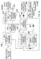
Fig. 5 , a further embodiment designated 10B of a closed cycle power system (similar to the embodiment described with reference toFig.1 ) is shown, whereinLNG pump 40A is used to pressurize the LNG prior to supplying it to condenser 30A to a pressure, e.g. about 80 bar, for producing a pressure for the re-gasified LNG suitable for supply vialine 43 to a pipeline for distribution of vaporized LNG to end users.Pump 40B is used rather than compressor in the embodiment shown inFig. 1 . Basically, the operation of the present embodiment is similar to the operation of the embodiment of the present invention described with reference toFigs. 1 and2 . Consequently, this embodiment is more efficient. Preferably,turbine 25B included in this embodiment, rotates at 1500 RPM or 1800 RPM. Furthermore, a mixture of propane and ethane or equivalents is the preferred working fluid for closed organic Rankine power system in this embodiment. However, ethane, ethene or other suitable organic working fluids can also be used in this embodiment. This is because the cooling curve of the propane/ethane mixture organic working fluid in thecondenser 30A is more suited to the heating curve of LNG at such high pressures enabling the LNG cooling source to be used more effectively (seeFig. 6 ). However, if preferred, a dual pressure organic Rankine cycle using a single organic working fluid e.g. preferably ethane, ethene or an equivalent, can be used here wherein two different expansion levels and also two condensers can be used (seeFig. 7 ). As can be seen, expanded organic vapors are extracted fromturbine 25B in an intermediate stage vialine 26B and supplied tocondenser 31B wherein organic working fluid condensate is produced. In addition, further expanded organic vapors exitturbine 25B vialine 27B and are supplied tofurther condenser 30B wherein further organic working fluid condensate is produced. Preferably,turbine 25B rotates at 1500 RPM or 1800 RPM. Condensate produced incondensers vaporizer 20B using cycle pump II, 16B and cycle pump I, 15B, respectively where sea water (or other equivalent heating) is supplied thereto vialine 18B for providing heat to the liquid working fluid present invaporizer 20B and producing vaporized working fluid.Condensers LNG using pump 40B so that the LNG is pressurized to a relatively high pressure e.g. about 80 bars. As can be seen fromFig. 7 , the LNG is supplied first of all to condenser 30B for condensing the relatively low pressure organic working fluidvapor exiting turbine 25B and thereafter, the heatedLNG exiting condenser 30B is supplied tocondenser 31B for condensing the relatively higher pressure organic working fluid vapor extracted fromturbine 25B. Thus, in accordance with this embodiment of the present invention, the supply rate or mass flow of the working fluid in the bleed cycle, i.e. line 26,condenser 31B and cycle pump I, 15B, can be increased so that additional power can be produced. Thereafter, the further heatedLNG exiting condenser 31B is preferably supplied toheater 36B for producing LNG vapor which may held in storage 42B or, alternatively, be delivered by throughline 43B to a pipeline for distribution of vaporized LNG to end users. While only one turbine is shown inFig. 7 , if preferred, two separate turbine modules, i.e. a high pressure turbine module and a low pressure turbine module, can be used. - In an alternative version (see
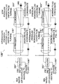
Fig. 7A ) of the last mentioned embodiment, direct-contact condenser/heater 32B' can be used together withcondensers 30B' and 31B'. By using direct-contact condenser/heater 32B', it is ensured that the working fluid supplied tovaporizer 20B' will not be cold and thus there will be little danger of freezing sea water or heating medium in the vaporizer. In addition, the mass flow of the working fluid in the power cycle can be further increased thereby permitting an increase in the power produced. Furthermore, thereby, the dimensions of the turbine at e.g. its first stage can be improved, e.g. permit the use of blades having a larger size. Consequently, the turbine efficiency is increased. - In a still further alternative version (see
Fig. 7B ) of the embodiment described with reference toFig. 7 ,reheater 22B" is included and used in conjunction with direct-contact condenser/heater 32B" andcondensers 30B" and 31B". By including the reheater, the wetness of the vapors exiting high-pressure turbine module 24B" will be substantially reduced or eliminated thus ensuring that the vapors supplied to low-pressure turbine module 25B are substantially dry so that effective expansion and power production can be achieved. If preferred, one heat source can be used for providing heat for the vaporizer while another heat source can be provided for supplying for the reheater. - In both alternatives described with reference to
Figs. 7A or7B , the position of direct contact condenser/heaters 32B' and 32B" can be changed such that the inlet of direct contact condenser/heaters 32B' can receive working fluid condensate exitingintermediate pressure condenser 31B' (seeFig. 7A ) while direct contact condenser/heaters 32B" can receive pressurized working fluid condensate exitingcycle pump 16B" (seeFig. 7B ). - In an additional alternative version (see
Fig. 7C ) of the embodiment described with reference toFig. 7 , condensate produced inlow pressure condenser 30B''' (orlow pressure condenser 30B"") can also be supplied tointermediate pressure condenser 31B"' (intermediate pressure condenser 31B"") to produce condensate from intermediate pressure vapor extracted from an intermediate stage of the turbine by indirect or direct contact respectively. -
Fig. 7D shows a still further alternative version of the embodiment described with reference toFig. 7 wherein rather than using a direct contact condenser/heater, an indirect condenser/heater is used. In this alternative, only one cycle pump can be used wherein suitable valves can be used in the intermediate pressure condensate lines. - In an alternative shown in
Fig. 7E , only one indirect condenser using LNG is used while a direct contact condenser/heater is also used. - In an additional embodiment of the present invention (see
Fig. 7F ), numeral 50A designates an open cycle power plant wherein portion of the LNG is drawn off the main line of the LNG and cycled through a turbine for producing power. In this embodiment, two direct contact condenser/heaters are used for condensing vapor extracted and exiting the turbine respectively using pressurized LNG pressurized bypump 55A prior to supply to the direct contact condenser/heaters. - In an alternative version, designated 50B in
Fig. 7G , of the embodiment described with reference toFig. 7F using an open cycle power plant,reheater 72B is included and used in conjunction with direct-contact condenser/heaters - In a still further alternative option of the embodiment described with reference to
Fig. 7F wherein an open cycle power plant is used, two indirect contact condensers can be used rather than the direct contact condensers used in the embodiment described with reference toFig. 7F . Two different configurations for the two indirect contact condensers can be used (seeFigs. 7H and7I ). - In an additional alternative option of the embodiment described with reference to
Fig. 7F wherein an open cycle power plant is used, an additional direct contact condenser/ heater can be used in addition to the two indirect contact condensers (seeFig. 7J ). - Furthermore, if preferred, in a further alternative option, see
Fig. 7K , of the embodiment described with reference toFig. 7F wherein an open cycle power plant is used, one direct contact condenser and one indirect contact condenser can be used. - Moreover, in a further embodiment, if preferred, in an open cycle power plant, one direct contact condenser or one indirect contact condenser can be used (see
Fig. 7L ). - In addition, in a further embodiment, if preferred, an open cycle power plant and closed cycle power plant can be combined (see
Fig. 7M ). In this embodiment, any of the described alternatives can be used as part of the open cycle power plant portion and/or closed cycle power plant portion. - Furthermore, it should be pointed out that, if preferred, the components of the various alternatives can be combined. Furthermore, also if preferred, certain components can be omitted from the alternatives. Additionally, an alternative used in a closed cycle power plant can be used in an open cycle power plant. E.g. the alternative described with reference to
Fig. 7C (closed cycle power plant) can be used in an open cycle power plant (e.g. condensers 30B'" and 31B"' can be used instead ofcondeners 33B' and 34B' shown inFig. 7H ,condensers 30B"" and 31B"" can be used instead ofcondensers 33B' and 34B' shown inFig. 7H ). - In addition, while two pressure levels are described herein, if preferred, several or a number of pressure levels can be used and, if preferred, an equivalent number of condensers can be used to provide effective use of the pressurized LNG as a cold sink or source for the power cycles.
- In
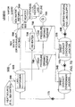
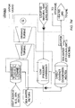
Fig. 8 , a further embodiment of the present invention is shown wherein a closed organic Rankine cycle power system is used. Numeral 1OC designates a power plant system includingsteam turbine system 100 as well closed is used as well as organic Rankine cycle power system 35C. Also hereLNG pump 40C is preferably used for pressurizing the LNG prior to supplying it to condenser 30C to a pressure, e.g. about 80 bar, for producing a pressure for the re-gasified LNG suitable for supply vialine 43C to a pipeline for distribution of vaporized LNG to end users. In this embodiment, the preferred organic working fluid is ethane or equivalent. Preferably in this embodiment,power plant system 10C includes, in addition,gas turbine unit 125 the exhaust gas of which providing the heat source forsteam turbine system 100. In such a case, as can be seen fromFig. 8 , the exhaust gas ofgas turbine 124 is supplied tovaporizer 120 for producing steam from water contained therein. The steam produced is supplied tosteam turbine 105 where it expands and produces power and preferably driveselectric generator 110 generating electricity. The expanded steam is supplied to steam condenser/vaporizer 120C where steam condensate is produced andcycle pump 115 supplies the steam condensate to vaporizer 120 thus completing the steam turbine cycle. Condenser/vaporizer 120C also acts as a vaporizer and vaporizes liquid organic working fluid present therein. The organic working fluid vapor produced is supplied toorganic vapor turbine 25C and expands therein and produces power and preferably driveselectric generator 28C that generates electricity. Preferably,turbine 25C rotates at 1500 RPM or 1800 RPM. Expanded organic working fluid vapor exiting organic vapor turbine is supplied tocondenser 30C where organic working fluid condensate is produced by pressurized LNG supplied thereto byLNG pump 40C.Cycle pump 15C supplies the organic working fluid condensate fromcondenser 30C to condenser/vaporizer 120C. Pressurized LNG is heated incondenser 30C and preferablyheater 36C further the pressurized LNG so that re-gasified LNG is produced for storage or supply via a pipeline for distribution of vaporized LNG to end users. Due to pressurizing of the LNG prior to supplied the LNG to the condenser, it can be advantageous to use a propane/ethane mixture as the organic working fluid of the organic Rankine cycle power system rather than ethane mentioned above. On the other hand, if preferred ethane, ethene or equivalent can be used as the working fluid while two condensers or other configurations mentioned above can be used in the organic Rankine cycle power system. - Turning to
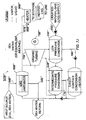
Fig. 9 , a further embodiment of the present invention is shown wherein a closed organic Rankine cycle power system is used. Numeral 1OD designates a power plant system including intermediatepower cycle system 100D as well as closed organic Rankine cycle power system 86D. Also hereLNG pump 40D is preferably used for pressurizing the LNG prior to supplying it to condenser 30D to a pressure, e.g. about 80 bar, for producing a pressure for the re-gasified LNG suitable for supply vialine 43D to a pipeline for distribution of vaporized LNG to end users. In this embodiment, the preferred organic working fluid is ethane, ethene or equivalent. Preferably, in this embodiment,power plant system 10D includesgas turbine unit 125D the exhaust gas of which providing the heat source for intermediate heattransfer cycle system 100D. In such a case, as can be seen fromFig. 9 , the exhaust gas ofgas turbine 124D is supplied to anintermediate cycle 100D for transferring heat from the exhaust gas of thevaporizer 120D for producing intermediate fluid vapor from intermediate fluid liquid contained therein. The vapor produced is supplied tointermediate vapor turbine 105D where it expands and produces power and preferably driveselectric generator 110D generating electricity. Preferably,turbine 25D rotates at 1500 RPM or 1800 RPM. The expanded vapor is supplied to vapor condenser/vaporizer 120D where intermediate fluid condensate is produced andcycle pump 115D supplies the intermediate fluid condensate to vaporizer 120 thus completing the intermediate fluid turbine cycle. Several working fluids are suitable for use in the intermediate cycle. An example of such a working fluid is pentane, i.e. n-pentane or iso-pentane. Condenser/vaporizer 120D also acts as an vaporizer and vaporizes liquid organic working fluid present therein. The organic working fluid vapor produced is supplied toorganic vapor turbine 25D and expands therein and produces power and preferably driveselectric generator 28D that generates electricity. Expanded organic working fluid vapor exiting organic vapor turbine is supplied tocondenser 30D where organic working fluid condensate is produced by pressurized LNG supplied thereto byLNG pump 40D.Cycle pump 15D supplies the organic working fluid condensate fromcondenser 30D to condenser/vaporizer 120D. Pressurized LNG is heated incondenser 30D and preferably heater 36D further the pressurized LNG so that regasified LNG is produced for storage or supply via a pipeline for distribution of vaporized LNG to end users. Due to pressurizing of the LNG prior to supplied the LNG to the condenser, it can be advantageous to use a propane/ethane mixture as the organic working fluid of the organic Rankine cycle power system rather than ethane mentioned above. On the other hand, if preferred ethane, ethene or equivalent can be used as the working fluid while two condensers or other configurations mentioned above can be used in the organic Rankine cycle power system. Furthermore, a heat transfer fluid such as thermal oil or other suitable heat transfer fluid can be used for transferring heat from the hot gas to the intermediate fluid and, if preferred, a heat transfer fluid such as an organic, alkylated heat transfer fluid e.g. a synthetic alkylated aromatic heat transfer fluid. Examples can be an alkyl substituted aromatic fluid, Therminol LT, of the Solutia company having a center in Belgium or a mixture of isomers of an alkylated aromatic fluid, Dowterm J, of the Dow Chemical Company. Also other fluids such as hydrocarbons having the formula CnH2n+2 wherein n is between 8 and 20 can also be used for this purpose. Thus, iso-dodecane or 2,2,4,6,6-pentamethylheptane, iso-eicosane or 2,2,4,4,6,6,8,10,10-nonamethylundecane, iso-hexadecane or 2,2,4,4,6,8,8-heptamethylnonane, iso-octane or 2, 2, 4 trimethylpentane, iso-nonane or 2,2,4,4 tetramethylpentane and a mixture of two or more of said compounds can be used for such a purpose, in accordance withUS patent application serial no. 11/067,710 , the disclosure of which is hereby incorporated by reference. When an organic, alkylated heat transfer fluid is used as the heat transfer fluid, it can be used to also produce power or electricity by e.g. having vapors produced by heat in the hot gas expand in a turbine, with the expanded vapors exiting the turbine being condensed in a condenser which is cooled by intermediate fluid such that intermediate fluid vapor is produced which is supplied to the intermediate vapor turbine. - Furthermore, any of the alternatives described herein can be used in the embodiments described with reference to
Fig. 8 orFig. 9 . - While in the embodiments and alternatives described above it is stated that the preferred rotational speed of the turbine is 1500 or 1800 RPM, if preferred, in accordance with the present invention, other speeds can also be used, e.g. 3000 or 3600 RPM.
- If preferred, the methods of the present invention can also be used to cool the inlet air of a gas turbine and/or to carry out intercooling in an intermediate stage or stages of the compressor of a gas turbine. Furthermore, if preferred, the methods of the present invention can be used such that LNG after cooling and condensing the working fluid can be used to cool the inlet air of a gas turbine and/or used to carry out intercooling in an intermediate stage or stages of the compressor of a gas turbine.
- While methane, ethane, ethene or equivalents are mentioned above as the preferred working fluids for the organic Rankine cycle power plants they are to be taken as non-limiting examples of the preferred working fluids. Thus, other saturated or unsaturated aliphatic hydrocarbons can also be used as the working fluid for the organic Rankine cycle power plants. In addition, substituted saturated or unsaturated hydrocarbons can also be used as the working fluids for the organic Rankine cycle power plants. Trifluromethane (CHF3), fluromethane (CH3F), tetrafluroethane (C2F4) and hexafluroethane (C2F6) are also preferred working fluids for the organic Rankine cycle power plants described herein. Furthermore; such Chlorine (Cl) substituted saturated or unsaturated hydrocarbons can also be used as the working fluids for the organic Rankine cycle power plants but would not be used due to their negative environmental impact.
- Auxiliary equipment (e.g. values, controls, etc.) are not shown in the figures for sake of simplicity.
- While some embodiments of the invention have been described by way of illustration, it will be apparent that the invention can be carried into practice with many modifications, variations and adaptations, and with the use of numerous equivalents or alternative solutions that are within the scope of persons skilled in the art, without exceeding the scope of the claims.
Claims (18)
- A closed organic Rankine cycle power system and regasification system (10B', 10B", 10B""', 10B""") based on liquefied natural gas, LNG, comprising:a) a vaporizer (20B', 20B", 20B""', 20B""") in which liquid working fluid is vaporized, said liquid working fluid being a working fluid liquefied by the LNG;b) a turbine (25B', 25B", 25B""', 25B""") for expanding the vaporized working fluid and producing power;c) a condenser (30B', 30B", 30B"', 30B"", 30B'"", 30B""") to which expanded working fluid vapour is supplied, said condenser also being supplied with LNG for receiving heat from said expanded fluid vapour wherein said LNG condenses said expanded working fluid exiting the turbine and whereby the temperature of the LNG increases as it flows through the condenser;d) a line (43B', 43B", 43B"', 43B"", 43B""', 43B""") for transmitting regasified LNG
characterised by:e) a condenser/heater (32B', 32B") for condensing vapors extracted from an intermediate stage of said turbine and heating working fluid condensate supplied to said condenser/heater from said condenser. - The system according to claim 1, wherein the working fluid is ethane or methane.
- The system according to claim 1, wherein the working fluid is a mixture of propane and ethane.
- The system according to claim 1, 2 or 3 wherein the power system further includes an open cycle power system such that the working fluid therein is LNG, having a heat exchanger means for condensing the LNG exiting the turbine of open cycle power system and heating the LNG supplied to the system.
- The system according to any one proceeding claim, wherein the heat source of the vaporizer is sea water.
- The system according to claim 1, wherein the heat source of the vaporizer comprises steam exiting a steam turbine (105) wherein said steam turbine is a portion of a combined cycle power plant having a gas turbine power system (125) in which the exhaust gases of said gas turbine power system (125) provide heat for producing steam which is supplied to said steam turbine (105).
- The system according to claim 1, further comprising an intermediate fluid system (100D) for transferring heat from the heat source to said working fluid, wherein said intermediate fluid system (100D) includes a condenser (120D) that transfers heat from the intermediate fluid to the working fluid for vaporizing the working fluid.
- The system according to claim 1, further comprising a pump (1.5", 17B""") for delivering liquid working fluid to the vaporizer.
- The system according to claim 1 further comprising a pump (40B", 40B"''') for increasing the pressure of the LNG prior to supplying it to said condenser to a pressure that is suitable for supplying the re-gasified LNG along a pipeline to end users.
- The system according to claim 6 or 7 further comprising a pump (40C) for increasing the pressure of the LNG prior to supplying it to said condenser (120D) to a pressure that is suitable for supplying the re-gasified LNG along a pipeline to end users.
- The system according to claim 1 further comprising a further condenser (31B', 31B", 31B"', 31B"", 31B""') for condensing expanded vapour extracted from said turbine wherein said further condenser is cooled by heated LNG exiting said condenser.
- The system according to claim 1 wherein said condenser/heater for condensing vapors extracted from an intermediate stage of said turbine and heating working fluid condensate supplied to said condenser/heater comprises an indirect contact condenser/heater.
- The system according to claim 1 wherein said condenser/heater for condensing vapors extracted from an intermediate stage of said turbine and heating working fluid condensate supplied to said condenser/heater comprises a direct contact condenser/heater (32B").
- The system according to claim 4, wherein said heat exchanger means for condensing the LNG exiting the turbine of said open cycle power system is cooled by pressurized LNG.
- The system according to claim 14 further comprising a further heat exchanger means for condensing the LNG extracted from said turbine of said open cycle power system wherein said further heat exchanger means is cooled by heated LNG exiting said heat exchanger means.
- The system according to claim 4 wherein said open cycle power system further comprise a condenser/heater for condensing vapors extracted from an intermediate stage of said turbine of open cycle power system and heating LNG supplied to said condenser/heater from said heat exchanger means of said open cycle power system.
- The system according to claim 1 or 11 further characterized in that said turbine comprises a high pressure organic turbine module (24B") and a low pressure organic turbine module (25B") wherein said intermediate stage of said turbine comprises the exit of said high pressure organic turbine module (24B") from which vapors are extracted.
- The system according to claim 17 further characterized in that said condenser/heater for condensing vapors extracted from an intermediate stage of said turbine and heating working fluid condensate supplied to said condenser/heater comprises a direct contact condenser/heater (32B") for condensing vapors extracted from said exit of high pressure organic turbine module (24B") and heating working fluid condensate supplied to said direct contact condenser/heater (32B").
Applications Claiming Priority (2)
| Application Number | Priority Date | Filing Date | Title |
|---|---|---|---|
| US11/110,935 US7493763B2 (en) | 2005-04-21 | 2005-04-21 | LNG-based power and regasification system |
| PCT/IL2006/000450 WO2006111957A2 (en) | 2005-04-21 | 2006-04-10 | Lng-based powerand rbgasification system |
Publications (3)
| Publication Number | Publication Date |
|---|---|
| EP1888883A2 EP1888883A2 (en) | 2008-02-20 |
| EP1888883A4 EP1888883A4 (en) | 2009-07-22 |
| EP1888883B1 true EP1888883B1 (en) | 2010-12-29 |
Family
ID=37115555
Family Applications (1)
| Application Number | Title | Priority Date | Filing Date |
|---|---|---|---|
| EP06728251A Expired - Lifetime EP1888883B1 (en) | 2005-04-21 | 2006-04-10 | Lng-based power and regasification system |
Country Status (11)
| Country | Link |
|---|---|
| US (1) | US7493763B2 (en) |
| EP (1) | EP1888883B1 (en) |
| JP (1) | JP4918083B2 (en) |
| KR (1) | KR101280799B1 (en) |
| AT (1) | ATE493567T1 (en) |
| CA (1) | CA2605001C (en) |
| DE (1) | DE602006019239D1 (en) |
| ES (1) | ES2357755T3 (en) |
| MX (1) | MX2007012942A (en) |
| PT (1) | PT1888883E (en) |
| WO (1) | WO2006111957A2 (en) |
Cited By (4)
| Publication number | Priority date | Publication date | Assignee | Title |
|---|---|---|---|---|
| FR2976317A1 (en) * | 2011-06-10 | 2012-12-14 | Elengy | System for generating electricity, has sampling device maintaining specific ratio of flow rate of recycled portion and flow rate of high pressure gas and providing emission gas to gas transportation and distribution system |
| WO2013130557A1 (en) * | 2012-02-28 | 2013-09-06 | Teracool, Llc | System and methods for data center cooling and power generation using liquefied natural gas |
| US9903232B2 (en) | 2011-12-22 | 2018-02-27 | Ormat Technologies Inc. | Power and regasification system for LNG |
| CN110159378A (en) * | 2019-06-05 | 2019-08-23 | 广东海洋大学 | A kind of natural gas overbottom pressure cold energy use system |
Families Citing this family (31)
| Publication number | Priority date | Publication date | Assignee | Title |
|---|---|---|---|---|
| JPS58103659A (en) * | 1981-12-16 | 1983-06-20 | Toshiba Corp | Production of ion selective membrane |
| CA2682684C (en) * | 2007-04-13 | 2012-07-17 | Fluor Technologies Corporation | Configurations and methods for offshore lng regasification and heating value conditioning |
| USRE46316E1 (en) * | 2007-04-17 | 2017-02-21 | Ormat Technologies, Inc. | Multi-level organic rankine cycle power system |
| CA2686850A1 (en) * | 2007-05-30 | 2008-12-11 | Fluor Technologies Corporation | Lng regasification and power generation |
| US7900452B2 (en) * | 2007-06-19 | 2011-03-08 | Lockheed Martin Corporation | Clathrate ice thermal transport for ocean thermal energy conversion |
| US7900451B2 (en) * | 2007-10-22 | 2011-03-08 | Ormat Technologies, Inc. | Power and regasification system for LNG |
| WO2009070379A1 (en) * | 2007-11-30 | 2009-06-04 | Exxonmobil Upstream Research Company | Integrated lng re-gasification apparatus |
| US8375716B2 (en) * | 2007-12-21 | 2013-02-19 | United Technologies Corporation | Operating a sub-sea organic Rankine cycle (ORC) system using individual pressure vessels |
| US20090284011A1 (en) * | 2008-05-16 | 2009-11-19 | Mcbride Thomas S | Continuos-Absorption Turbine |
| CN105423125B (en) * | 2008-07-17 | 2018-03-20 | 氟石科技公司 | It is used for Waste Heat Recovery and the arrangements and methods of ambient air vaporizer in lng regas |
| US8237299B2 (en) * | 2009-06-26 | 2012-08-07 | Larry Andrews | Power generation systems, processes for generating energy at an industrial mine site, water heating systems, and processes of heating water |
| EP2278210A1 (en) | 2009-07-16 | 2011-01-26 | Shell Internationale Research Maatschappij B.V. | Method for the gasification of a liquid hydrocarbon stream and an apparatus therefore |
| WO2011103560A2 (en) * | 2010-02-22 | 2011-08-25 | University Of South Florida | Method and system for generating power from low- and mid- temperature heat sources |
| US20120000201A1 (en) * | 2010-06-30 | 2012-01-05 | General Electric Company | System and method for generating and storing transient integrated organic rankine cycle energy |
| ES2396790B1 (en) * | 2011-07-13 | 2014-01-17 | Bordebi Técnicas Energéticas Del Frio, S.L. | MODULAR SYSTEM FOR THE USE OF COLD AND / OR BOG IN A LICUATED NATURAL GAS REGASIFICATION PLANT |
| JP5800295B2 (en) * | 2011-08-19 | 2015-10-28 | 国立大学法人佐賀大学 | Steam power cycle system |
| ITMI20120852A1 (en) * | 2012-05-17 | 2013-11-18 | Exergy Orc S R L | ORC SYSTEM FOR THE PRODUCTION OF ENERGY BY ORGANIC RANKINE CYCLE |
| DE102012020304A1 (en) * | 2012-08-23 | 2014-02-27 | Linde Aktiengesellschaft | Process for vaporizing LNG |
| ITFI20120193A1 (en) | 2012-10-01 | 2014-04-02 | Nuovo Pignone Srl | "AN ORGANIC RANKINE CYCLE FOR MECHANICAL DRIVE APPLICATIONS" |
| JP2014122563A (en) * | 2012-12-20 | 2014-07-03 | Toshiba Corp | Floating body type power plant |
| MX385879B (en) * | 2013-07-19 | 2025-03-18 | Itm Power Res Limited | PRESSURE REDUCTION SYSTEM. |
| EP3094931B1 (en) | 2014-01-13 | 2017-12-13 | Carrier Corporation | Fuel regeneration using waste heat of refrigeration unit |
| US9598152B2 (en) | 2014-04-01 | 2017-03-21 | Moran Towing Corporation | Articulated conduit systems and uses thereof for fluid transfer between two vessels |
| AU2016359565B2 (en) * | 2015-11-24 | 2021-11-04 | Yakov Elgart | Method and system of combined power plant for waste heat conversion to electrical energy, heating and cooling |
| CN105545388B (en) * | 2016-03-10 | 2017-02-22 | 钟学斌 | Low-temperature thermal energy recycling unit and method |
| US10718236B2 (en) * | 2016-09-19 | 2020-07-21 | Ormat Technologies, Inc. | Turbine shaft bearing and turbine apparatus |
| IT201700070318A1 (en) | 2017-06-23 | 2018-12-23 | Exergy Spa | Rankine cycle plant and process for the liquefied gas regasification |
| IT201800008157A1 (en) * | 2018-08-22 | 2020-02-22 | Saipem Spa | CRYOGENIC THERMODYNAMIC CYCLE WITH THERMAL RECOVERY |
| WO2021118470A1 (en) | 2019-12-13 | 2021-06-17 | Nanyang Technological University | Cryogenic energy system for cooling and powering an indoor environment |
| IT202000018628A1 (en) * | 2020-07-30 | 2022-01-30 | Saipem Spa | PROCESS FOR LNG GASIFICATION AND LOW TEMPERATURE POWER GENERATION |
| CN120019197A (en) * | 2022-06-17 | 2025-05-16 | 二十20能源系统私人有限公司 | Power Generation System |
Family Cites Families (10)
| Publication number | Priority date | Publication date | Assignee | Title |
|---|---|---|---|---|
| CH588635A5 (en) * | 1975-02-07 | 1977-06-15 | Sulzer Ag | |
| JPS5491648A (en) | 1977-12-29 | 1979-07-20 | Toyokichi Nozawa | Lnggfleon generation system |
| US4562995A (en) * | 1982-03-31 | 1986-01-07 | Daikin Kogyo Co., Ltd. | Working fluids for Rankine cycle |
| BR9405757A (en) | 1993-12-10 | 1995-11-28 | Cabot Corp | Process to increase combined cycle installation capacity and efficiency and liquefied natural gas combined cycle installation system |
| US5687570A (en) | 1994-02-28 | 1997-11-18 | Ormat Industries Ltd. | Externally fired combined cycle gas turbine system |
| US5615561A (en) | 1994-11-08 | 1997-04-01 | Williams Field Services Company | LNG production in cryogenic natural gas processing plants |
| US6336316B1 (en) | 1998-12-21 | 2002-01-08 | Japan Science And Technology Corp. | Heat engine |
| MXPA02000764A (en) * | 1999-07-22 | 2002-07-22 | Bechtel Corp | A method and apparatus for vaporizing liquid gas in a combined cycle power plant. |
| US6690839B1 (en) * | 2000-01-17 | 2004-02-10 | Tektronix, Inc. | Efficient predictor of subjective video quality rating measures |
| US6960839B2 (en) | 2000-07-17 | 2005-11-01 | Ormat Technologies, Inc. | Method of and apparatus for producing power from a heat source |
-
2005
- 2005-04-21 US US11/110,935 patent/US7493763B2/en active Active
-
2006
- 2006-04-10 JP JP2008507262A patent/JP4918083B2/en not_active Expired - Lifetime
- 2006-04-10 DE DE602006019239T patent/DE602006019239D1/en not_active Expired - Lifetime
- 2006-04-10 KR KR1020077027096A patent/KR101280799B1/en not_active Expired - Fee Related
- 2006-04-10 PT PT06728251T patent/PT1888883E/en unknown
- 2006-04-10 EP EP06728251A patent/EP1888883B1/en not_active Expired - Lifetime
- 2006-04-10 WO PCT/IL2006/000450 patent/WO2006111957A2/en not_active Ceased
- 2006-04-10 CA CA2605001A patent/CA2605001C/en not_active Expired - Fee Related
- 2006-04-10 ES ES06728251T patent/ES2357755T3/en not_active Expired - Lifetime
- 2006-04-10 MX MX2007012942A patent/MX2007012942A/en active IP Right Grant
- 2006-04-10 AT AT06728251T patent/ATE493567T1/en not_active IP Right Cessation
Cited By (4)
| Publication number | Priority date | Publication date | Assignee | Title |
|---|---|---|---|---|
| FR2976317A1 (en) * | 2011-06-10 | 2012-12-14 | Elengy | System for generating electricity, has sampling device maintaining specific ratio of flow rate of recycled portion and flow rate of high pressure gas and providing emission gas to gas transportation and distribution system |
| US9903232B2 (en) | 2011-12-22 | 2018-02-27 | Ormat Technologies Inc. | Power and regasification system for LNG |
| WO2013130557A1 (en) * | 2012-02-28 | 2013-09-06 | Teracool, Llc | System and methods for data center cooling and power generation using liquefied natural gas |
| CN110159378A (en) * | 2019-06-05 | 2019-08-23 | 广东海洋大学 | A kind of natural gas overbottom pressure cold energy use system |
Also Published As
| Publication number | Publication date |
|---|---|
| CA2605001A1 (en) | 2006-10-26 |
| WO2006111957A3 (en) | 2007-04-19 |
| JP4918083B2 (en) | 2012-04-18 |
| US20060236699A1 (en) | 2006-10-26 |
| WO2006111957B1 (en) | 2007-05-31 |
| EP1888883A2 (en) | 2008-02-20 |
| DE602006019239D1 (en) | 2011-02-10 |
| ES2357755T3 (en) | 2011-04-29 |
| WO2006111957A2 (en) | 2006-10-26 |
| KR101280799B1 (en) | 2013-07-03 |
| PT1888883E (en) | 2011-03-10 |
| JP2008537058A (en) | 2008-09-11 |
| US7493763B2 (en) | 2009-02-24 |
| CA2605001C (en) | 2013-05-28 |
| KR20080032022A (en) | 2008-04-14 |
| MX2007012942A (en) | 2007-12-12 |
| ATE493567T1 (en) | 2011-01-15 |
| EP1888883A4 (en) | 2009-07-22 |
Similar Documents
| Publication | Publication Date | Title |
|---|---|---|
| CA2605001C (en) | Lng-based power and regasification system | |
| EP2217847B1 (en) | A power and regasification system for lng | |
| US9903232B2 (en) | Power and regasification system for LNG | |
| US20100083670A1 (en) | Method for vaporizing and heating crycogenic fluid | |
| KR100191080B1 (en) | Power generation from lng | |
| RU2464480C2 (en) | Method and device for evaporation of liquefied natural gas and its storage | |
| CN109386316B (en) | LNG cold energy and BOG combustion energy combined utilization system and method | |
| GB2540080A (en) | Cold utilization system, energy system provided with cold utilization system, and method for utilizing cold utilization system | |
| Lee et al. | Thermodynamic assessment of integrated heat recovery system combining exhaust-gas heat and cold energy for LNG regasification process in FSRU vessel | |
| KR20010042204A (en) | Producing power from liquefied natural gas | |
| WO2020201871A1 (en) | Recompressed transcritical cycle with vaporization in cryogenic or low-temperature applications, and/or with coolant fluid | |
| WO2014152720A1 (en) | Thermal energy conversion system for regasification of cryogenic liquids | |
| EP3548714B1 (en) | Organic rankine cycle in cryogenic applications or refrigerating fluids | |
| KR102897566B1 (en) | Floating Storage Power Plant | |
| Iordan et al. | RECOVERY OF LOW-TEMPERATURE WASTE HEAT AND LNG COLD ENERGY. | |
| NO332506B1 (en) | Regassification of LNG with Rankin circuit |
Legal Events
| Date | Code | Title | Description |
|---|---|---|---|
| PUAI | Public reference made under article 153(3) epc to a published international application that has entered the european phase |
Free format text: ORIGINAL CODE: 0009012 |
|
| 17P | Request for examination filed |
Effective date: 20071116 |
|
| AK | Designated contracting states |
Kind code of ref document: A2 Designated state(s): AT BE BG CH CY CZ DE DK EE ES FI FR GB GR HU IE IS IT LI LT LU LV MC NL PL PT RO SE SI SK TR |
|
| DAX | Request for extension of the european patent (deleted) | ||
| A4 | Supplementary search report drawn up and despatched |
Effective date: 20090623 |
|
| 17Q | First examination report despatched |
Effective date: 20091014 |
|
| GRAP | Despatch of communication of intention to grant a patent |
Free format text: ORIGINAL CODE: EPIDOSNIGR1 |
|
| RTI1 | Title (correction) |
Free format text: LNG-BASED POWER AND REGASIFICATION SYSTEM |
|
| GRAS | Grant fee paid |
Free format text: ORIGINAL CODE: EPIDOSNIGR3 |
|
| GRAA | (expected) grant |
Free format text: ORIGINAL CODE: 0009210 |
|
| AK | Designated contracting states |
Kind code of ref document: B1 Designated state(s): AT BE BG CH CY CZ DE DK EE ES FI FR GB GR HU IE IS IT LI LT LU LV MC NL PL PT RO SE SI SK TR |
|
| REG | Reference to a national code |
Ref country code: GB Ref legal event code: FG4D |
|
| REG | Reference to a national code |
Ref country code: CH Ref legal event code: EP |
|
| REG | Reference to a national code |
Ref country code: IE Ref legal event code: FG4D |
|
| REF | Corresponds to: |
Ref document number: 602006019239 Country of ref document: DE Date of ref document: 20110210 Kind code of ref document: P |
|
| REG | Reference to a national code |
Ref country code: DE Ref legal event code: R096 Ref document number: 602006019239 Country of ref document: DE Effective date: 20110210 |
|
| REG | Reference to a national code |
Ref country code: PT Ref legal event code: SC4A Free format text: AVAILABILITY OF NATIONAL TRANSLATION Effective date: 20110302 |
|
| REG | Reference to a national code |
Ref country code: NL Ref legal event code: T3 |
|
| PG25 | Lapsed in a contracting state [announced via postgrant information from national office to epo] |
Ref country code: LT Free format text: LAPSE BECAUSE OF FAILURE TO SUBMIT A TRANSLATION OF THE DESCRIPTION OR TO PAY THE FEE WITHIN THE PRESCRIBED TIME-LIMIT Effective date: 20101229 |
|
| REG | Reference to a national code |
Ref country code: ES Ref legal event code: FG2A Ref document number: 2357755 Country of ref document: ES Kind code of ref document: T3 Effective date: 20110429 |
|
| LTIE | Lt: invalidation of european patent or patent extension |
Effective date: 20101229 |
|
| PG25 | Lapsed in a contracting state [announced via postgrant information from national office to epo] |
Ref country code: SI Free format text: LAPSE BECAUSE OF FAILURE TO SUBMIT A TRANSLATION OF THE DESCRIPTION OR TO PAY THE FEE WITHIN THE PRESCRIBED TIME-LIMIT Effective date: 20101229 Ref country code: CY Free format text: LAPSE BECAUSE OF FAILURE TO SUBMIT A TRANSLATION OF THE DESCRIPTION OR TO PAY THE FEE WITHIN THE PRESCRIBED TIME-LIMIT Effective date: 20101229 Ref country code: SE Free format text: LAPSE BECAUSE OF FAILURE TO SUBMIT A TRANSLATION OF THE DESCRIPTION OR TO PAY THE FEE WITHIN THE PRESCRIBED TIME-LIMIT Effective date: 20101229 Ref country code: LV Free format text: LAPSE BECAUSE OF FAILURE TO SUBMIT A TRANSLATION OF THE DESCRIPTION OR TO PAY THE FEE WITHIN THE PRESCRIBED TIME-LIMIT Effective date: 20101229 Ref country code: BG Free format text: LAPSE BECAUSE OF FAILURE TO SUBMIT A TRANSLATION OF THE DESCRIPTION OR TO PAY THE FEE WITHIN THE PRESCRIBED TIME-LIMIT Effective date: 20110329 Ref country code: FI Free format text: LAPSE BECAUSE OF FAILURE TO SUBMIT A TRANSLATION OF THE DESCRIPTION OR TO PAY THE FEE WITHIN THE PRESCRIBED TIME-LIMIT Effective date: 20101229 Ref country code: AT Free format text: LAPSE BECAUSE OF FAILURE TO SUBMIT A TRANSLATION OF THE DESCRIPTION OR TO PAY THE FEE WITHIN THE PRESCRIBED TIME-LIMIT Effective date: 20101229 |
|
| PG25 | Lapsed in a contracting state [announced via postgrant information from national office to epo] |
Ref country code: EE Free format text: LAPSE BECAUSE OF FAILURE TO SUBMIT A TRANSLATION OF THE DESCRIPTION OR TO PAY THE FEE WITHIN THE PRESCRIBED TIME-LIMIT Effective date: 20101229 Ref country code: GR Free format text: LAPSE BECAUSE OF FAILURE TO SUBMIT A TRANSLATION OF THE DESCRIPTION OR TO PAY THE FEE WITHIN THE PRESCRIBED TIME-LIMIT Effective date: 20110330 Ref country code: CZ Free format text: LAPSE BECAUSE OF FAILURE TO SUBMIT A TRANSLATION OF THE DESCRIPTION OR TO PAY THE FEE WITHIN THE PRESCRIBED TIME-LIMIT Effective date: 20101229 Ref country code: IS Free format text: LAPSE BECAUSE OF FAILURE TO SUBMIT A TRANSLATION OF THE DESCRIPTION OR TO PAY THE FEE WITHIN THE PRESCRIBED TIME-LIMIT Effective date: 20110429 |
|
| PG25 | Lapsed in a contracting state [announced via postgrant information from national office to epo] |
Ref country code: RO Free format text: LAPSE BECAUSE OF FAILURE TO SUBMIT A TRANSLATION OF THE DESCRIPTION OR TO PAY THE FEE WITHIN THE PRESCRIBED TIME-LIMIT Effective date: 20101229 Ref country code: PL Free format text: LAPSE BECAUSE OF FAILURE TO SUBMIT A TRANSLATION OF THE DESCRIPTION OR TO PAY THE FEE WITHIN THE PRESCRIBED TIME-LIMIT Effective date: 20101229 Ref country code: SK Free format text: LAPSE BECAUSE OF FAILURE TO SUBMIT A TRANSLATION OF THE DESCRIPTION OR TO PAY THE FEE WITHIN THE PRESCRIBED TIME-LIMIT Effective date: 20101229 |
|
| PG25 | Lapsed in a contracting state [announced via postgrant information from national office to epo] |
Ref country code: DK Free format text: LAPSE BECAUSE OF FAILURE TO SUBMIT A TRANSLATION OF THE DESCRIPTION OR TO PAY THE FEE WITHIN THE PRESCRIBED TIME-LIMIT Effective date: 20101229 |
|
| PLBE | No opposition filed within time limit |
Free format text: ORIGINAL CODE: 0009261 |
|
| STAA | Information on the status of an ep patent application or granted ep patent |
Free format text: STATUS: NO OPPOSITION FILED WITHIN TIME LIMIT |
|
| PG25 | Lapsed in a contracting state [announced via postgrant information from national office to epo] |
Ref country code: MC Free format text: LAPSE BECAUSE OF NON-PAYMENT OF DUE FEES Effective date: 20110430 |
|
| REG | Reference to a national code |
Ref country code: CH Ref legal event code: PL |
|
| 26N | No opposition filed |
Effective date: 20110930 |
|
| REG | Reference to a national code |
Ref country code: DE Ref legal event code: R097 Ref document number: 602006019239 Country of ref document: DE Effective date: 20110930 |
|
| PG25 | Lapsed in a contracting state [announced via postgrant information from national office to epo] |
Ref country code: CH Free format text: LAPSE BECAUSE OF NON-PAYMENT OF DUE FEES Effective date: 20110430 Ref country code: LI Free format text: LAPSE BECAUSE OF NON-PAYMENT OF DUE FEES Effective date: 20110430 |
|
| REG | Reference to a national code |
Ref country code: IE Ref legal event code: MM4A |
|
| PG25 | Lapsed in a contracting state [announced via postgrant information from national office to epo] |
Ref country code: IE Free format text: LAPSE BECAUSE OF NON-PAYMENT OF DUE FEES Effective date: 20110410 |
|
| PG25 | Lapsed in a contracting state [announced via postgrant information from national office to epo] |
Ref country code: LU Free format text: LAPSE BECAUSE OF NON-PAYMENT OF DUE FEES Effective date: 20110410 |
|
| PGFP | Annual fee paid to national office [announced via postgrant information from national office to epo] |
Ref country code: DE Payment date: 20130403 Year of fee payment: 8 Ref country code: GB Payment date: 20130410 Year of fee payment: 8 |
|
| PG25 | Lapsed in a contracting state [announced via postgrant information from national office to epo] |
Ref country code: TR Free format text: LAPSE BECAUSE OF FAILURE TO SUBMIT A TRANSLATION OF THE DESCRIPTION OR TO PAY THE FEE WITHIN THE PRESCRIBED TIME-LIMIT Effective date: 20101229 |
|
| PG25 | Lapsed in a contracting state [announced via postgrant information from national office to epo] |
Ref country code: HU Free format text: LAPSE BECAUSE OF FAILURE TO SUBMIT A TRANSLATION OF THE DESCRIPTION OR TO PAY THE FEE WITHIN THE PRESCRIBED TIME-LIMIT Effective date: 20101229 |
|
| REG | Reference to a national code |
Ref country code: DE Ref legal event code: R119 Ref document number: 602006019239 Country of ref document: DE |
|
| GBPC | Gb: european patent ceased through non-payment of renewal fee |
Effective date: 20140410 |
|
| REG | Reference to a national code |
Ref country code: DE Ref legal event code: R119 Ref document number: 602006019239 Country of ref document: DE Effective date: 20141101 |
|
| PG25 | Lapsed in a contracting state [announced via postgrant information from national office to epo] |
Ref country code: GB Free format text: LAPSE BECAUSE OF NON-PAYMENT OF DUE FEES Effective date: 20140410 Ref country code: DE Free format text: LAPSE BECAUSE OF NON-PAYMENT OF DUE FEES Effective date: 20141101 |
|
| REG | Reference to a national code |
Ref country code: FR Ref legal event code: PLFP Year of fee payment: 11 |
|
| REG | Reference to a national code |
Ref country code: FR Ref legal event code: PLFP Year of fee payment: 12 |
|
| REG | Reference to a national code |
Ref country code: FR Ref legal event code: PLFP Year of fee payment: 13 |
|
| PGFP | Annual fee paid to national office [announced via postgrant information from national office to epo] |
Ref country code: NL Payment date: 20240315 Year of fee payment: 19 |
|
| PGFP | Annual fee paid to national office [announced via postgrant information from national office to epo] |
Ref country code: IT Payment date: 20240313 Year of fee payment: 19 Ref country code: FR Payment date: 20240308 Year of fee payment: 19 Ref country code: BE Payment date: 20240319 Year of fee payment: 19 |
|
| PGFP | Annual fee paid to national office [announced via postgrant information from national office to epo] |
Ref country code: PT Payment date: 20240409 Year of fee payment: 19 |
|
| PGFP | Annual fee paid to national office [announced via postgrant information from national office to epo] |
Ref country code: ES Payment date: 20250506 Year of fee payment: 20 |
|
| REG | Reference to a national code |
Ref country code: NL Ref legal event code: MM Effective date: 20250501 |
|
| PG25 | Lapsed in a contracting state [announced via postgrant information from national office to epo] |
Ref country code: PT Free format text: LAPSE BECAUSE OF NON-PAYMENT OF DUE FEES Effective date: 20251010 |
|
| REG | Reference to a national code |
Ref country code: BE Ref legal event code: MM Effective date: 20250430 |
|
| PG25 | Lapsed in a contracting state [announced via postgrant information from national office to epo] |
Ref country code: FR Free format text: LAPSE BECAUSE OF NON-PAYMENT OF DUE FEES Effective date: 20250430 Ref country code: NL Free format text: LAPSE BECAUSE OF NON-PAYMENT OF DUE FEES Effective date: 20250501 |
|
| PG25 | Lapsed in a contracting state [announced via postgrant information from national office to epo] |
Ref country code: BE Free format text: LAPSE BECAUSE OF NON-PAYMENT OF DUE FEES Effective date: 20250430 |
|
| PG25 | Lapsed in a contracting state [announced via postgrant information from national office to epo] |
Ref country code: IT Free format text: LAPSE BECAUSE OF NON-PAYMENT OF DUE FEES Effective date: 20250410 |
|
| REG | Reference to a national code |
Ref country code: ES Ref legal event code: FD2A Effective date: 20260430 |