EP1887718A1 - Method of operating an optical amplifier, optical amplifier and transmission system - Google Patents
Method of operating an optical amplifier, optical amplifier and transmission system Download PDFInfo
- Publication number
- EP1887718A1 EP1887718A1 EP06291298A EP06291298A EP1887718A1 EP 1887718 A1 EP1887718 A1 EP 1887718A1 EP 06291298 A EP06291298 A EP 06291298A EP 06291298 A EP06291298 A EP 06291298A EP 1887718 A1 EP1887718 A1 EP 1887718A1
- Authority
- EP
- European Patent Office
- Prior art keywords
- span
- output power
- spans
- transmission system
- contribution
- Prior art date
- Legal status (The legal status is an assumption and is not a legal conclusion. Google has not performed a legal analysis and makes no representation as to the accuracy of the status listed.)
- Granted
Links
Images
Classifications
-
- H—ELECTRICITY
- H04—ELECTRIC COMMUNICATION TECHNIQUE
- H04B—TRANSMISSION
- H04B10/00—Transmission systems employing electromagnetic waves other than radio-waves, e.g. infrared, visible or ultraviolet light, or employing corpuscular radiation, e.g. quantum communication
- H04B10/29—Repeaters
- H04B10/291—Repeaters in which processing or amplification is carried out without conversion of the main signal from optical form
- H04B10/293—Signal power control
- H04B10/2933—Signal power control considering the whole optical path
- H04B10/2935—Signal power control considering the whole optical path with a cascade of amplifiers
-
- H—ELECTRICITY
- H04—ELECTRIC COMMUNICATION TECHNIQUE
- H04B—TRANSMISSION
- H04B10/00—Transmission systems employing electromagnetic waves other than radio-waves, e.g. infrared, visible or ultraviolet light, or employing corpuscular radiation, e.g. quantum communication
- H04B10/25—Arrangements specific to fibre transmission
- H04B10/2507—Arrangements specific to fibre transmission for the reduction or elimination of distortion or dispersion
- H04B10/2543—Arrangements specific to fibre transmission for the reduction or elimination of distortion or dispersion due to fibre non-linearities, e.g. Kerr effect
Definitions
- the present invention relates to a method of operating an optical amplifier in an optical transmission system comprising a number of spans each having a respective line fibre, in particular in an optical transmission system comprising at least two different line fibre types with different tolerances to non-linearities, said amplifier being connected with a given line fibre span with respective characteristic span loss, L, and respective characteristic span non-linear tolerance, C, for operating said given span at an input power, P, corresponding to an output power of said amplifier.
- the present invention also relates to an optical amplifier for use in a span of an optical transmission system comprising a number of spans each having a respective line fibre, in particular in an optical transmission system comprising at least two different line fibre types with different tolerances to non-linearities, said amplifier being connected with a given line fibre span with respective characteristic span loss, L, and respective characteristic span non-linear tolerance, C, for operating said given span at an input power, P, corresponding to its output power.
- the present invention relates to an optical transmission system comprising a number of spans each having a respective line fibre with respective characteristic span loss, L, and respective characteristic span non-linear tolerance, C.
- Optical systems or networks e.g., Wavelength Division Multiplex (WDM) optical networks (hereinafter generally referred to as optical transmission systems) generally are heterogeneous. For instance, span lengths and losses may differ from one span to another.
- different types of optical fibres co-exist on a given network. Owing to their specific features, different line fibres such as single mode fibre (SMF), LEAF fibre, or the like, are predominantly used in optical transmission systems including Reconfigurable Optical Add-Drop Multiplexers (ROADMs), which are based on already existing systems. Therefore, heterogeneity of fibre types is mostly unavoidable in optical transmission systems.
- SMF single mode fibre
- LEAF fibre LEAF fibre
- ROADMs Reconfigurable Optical Add-Drop Multiplexers
- optical transmission systems according to the prior art has generally been based on homogeneity considerations.
- optical system design is often based on assumptions involving identical line spans of identical lengths, thus leading to performance estimators dedicated to homogeneous systems.
- the object is achieved by providing a method of the above-defined type, said method comprising the step of setting said output power relative to a reference output power, Pref, defined for a reference span with reference span loss, Lref, and reference span non-linear tolerance, Cref, said step of setting said output power comprising:
- the characteristic fibre span loss, L, and the characteristic span non-linear tolerance, C are typically expressed in decibel (dB).
- Input power, P, and reference output power, Pref are typically expressed in dBm.
- said reference span loss, Lref, and said reference span non-linear tolerance, Cref are also typically expressed in dB.
- Said characteristic span non-linear tolerance, C can be defined proportional to a maximum authorised input power, or a number of fibre spans multiplied by power, or non-linear cumulated phase, expressed on a dB scale, leading to a maximum tolerable value of transmission penalty (which value is usually pre-set), for an homogeneous dispersion-managed system composed of N such identical line fibre spans operated at a same input power.
- an optical amplifier of the above-defined type comprising means for setting said output power relative to a reference output power, Pref, defined for a reference span with reference span loss, Lref, and reference span non-linear tolerance, Cref, said means comprising:
- the object is achieved by providing an optical transmission system of the above-defined type, said optical transmission system comprising an optical amplifier according to said second aspect of the present invention.
- the present invention addresses the complete issue of optical transmission system heterogeneity, taking into account problems related to both different fibre types (i.e., non-linear effects) and span loss. In this way, optimum system performance can be achieved even in completely heterogeneous optical transmission systems.
- said first contribution is proportional to said first deviation.
- the latter comprises determining said second deviation as a function of a ratio Nmax/Nref, wherein Nmax is a maximum achievable number of spans for a transmission system composed of identical spans with said reference span loss, Lref, and said characteristic span non-linear tolerance, C, and wherein Nref is a maximum achievable number of spans for a transmission system composed of identical spans with said reference span loss, Lref, and said characteristic span non-linear tolerance, Cref, respectively, i.e., repeated occurrences of said spans in respective (hypothetical) optical transmission systems, for achieving a predefined transmission related characteristic.
- Said hypothetical or virtual system usually corresponds to a calibration that can be obtained for homogeneous systems.
- the general idea is to use said calibration to derive rules for heterogeneous systems.
- the value of C is characteristic of a entire system, i.e., a dispersion-managed system with identical spans, wherein said value further depends on a chosen bit rate, chosen channel spacing, and chosen modulation format. Said value cannot be measured directly or calculated easily, contrary to loss.
- the power or the transmission distance are varied to derive non-linear limitation.
- said second means are adapted to determine said second contribution as a function of a ratio Nmax/Nref, wherein Nmax is a maximum achievable number of spans for a transmission system composed of identical spans with said reference span loss, Lref, and said characteristic span non-linear tolerance, C, and wherein Nref is a maximum achievable number of spans for a transmission system composed of identical spans with said reference span loss, Lref, and said characteristic span non-linear tolerance, Cref, respectively, for achieving a predefined transmission related characteristic.
- said second deviation is proportional to a quantity log 10 (Nmax/Nref).
- said second means are adapted to determine said second contribution proportional to a quantity log 10 (Nmax/Nref).
- P Pref + ⁇ ⁇ ( L - Lref ) + 20 ⁇ ⁇ ⁇ log 10 Nmax / Nref , with 0.1 ⁇ ⁇ ⁇ 0.9 and 0.1 ⁇ ⁇ ⁇ 0.9.
- P Pref + ⁇ ⁇ ( L - Lref ) + ⁇ ⁇ C - Cref , with 0.1 ⁇
- non-linearities do accumulate with transmission distance.
- they are related to input power, but with amplification, the power is set to its maximum at the beginning of each span, thence the idea of using the product between number of spans and input power into each span to quantify the "amount" of non-linearities, as known to a person skilled in the art.
- a natural extension of the parameter "number of spans x power" is the non-linear cumulated phase along the transmission link, since it accounts for non-linearity accumulation in the line fibre spans, including Dispersion Compensating Fibres (DCFs).
- DCFs Dispersion Compensating Fibres
- Suitable values for said parameters ⁇ , ⁇ can be provided at system set-up for storing in the respective optical amplifiers.
- said parameters as well as other values needed for controlling output power in accordance with the present invention e.g., Pref, Lref, Cref, Nref, C, and/or Nmax
- Pref, Lref, Cref, Nref, C, and/or Nmax may be determined dynamically during operation by means of suitable monitoring means.
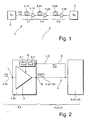
- Fig. 1 shows a schematic diagram of an optical transmission system 1 in accordance with the present invention.
- the optical transmission system 1 comprises a transmitter 2 and a receiver 3 for sending and receiving optical signals OS, respectively.
- Transmitter 2 and receiver 3 are connected by means of an optical transmission line 4 comprising a number of spans 4.1, 4.2, ..., 4.n.
- Each span has line fibre 4.1a, 4.2a, ..., 4.na and an optical amplifier 4.1 b, 4.2b, ..., 4.nb, typically a double-stage amplifier comprising a Dispersion Compensation Fibre (DCF).
- DCF Dispersion Compensation Fibre
- Each line fibre 4.1a, 4.2a, ..., 4.na can be characterised by a respective line fibre type in terms of attenuation, length, dispersion, effective area, etc.
- each span 4.1, 4.2, ... 4.n can have a line fibre and/or an optical amplifier of a different type, which results in different non-linear thresholds (NLT), hereinafter denoted as C, and different span loss L for each one of spans 4.1, 4.2, ..., 4.n.
- NLT non-linear thresholds
- NLT C is generally expressed in decibel (dB) and is proportional to the maximum power tolerated by a dispersion-managed homogeneous optical transmission system composed of a number of identical spans of a specific type. In other words: In case of excessive power said homogeneous optical transmission system will experience intolerable non-linear effects on optical signal OS.
- each one of spans 4.1, 4.2, ..., 4.n can also be characterised by its respective span loss L, also expressed in decibel (dB).
- each span 4.1, 4.2, ..., 4.n in optical transmission system 1 is a source of accumulation of non-linear effects on a transmitted optical signal OS (due to non-linear effects along optical transmission line 4) and of optical signal-to-noise ratio (OSNR) degradation (due to span losses L in terms of combined losses in line fibres 4.1a, 4.2a, 4.na and associated optical amplifiers 4.1 b, 4.2b, ..., 4.nb).
- OS optical signal-to-noise ratio
- optical transmission system 1 of Fig. 1 composed of a plurality of mutually different spans 4.1, 4.2, ..., 4.n.
- a reference span of loss Lref (expressed in dB) and non-linear tolerance Cref, which leads to a maximum achievable number Nref of spans for achieving said transmission-related characteristic, and which should be operated at a power Pref.
- the above defined operating power P for a given span is derived by suitably setting output power R relative to said reference power Pref by means of two mutually independent contributions.
- Said first contribution, ⁇ (L - Lref) is intended to compensate a first deviation in characteristic span loss between said reference span and said given span with characteristic loss L and characteristic NLT C.
- a second contribution, 20 ⁇ log 10 (Nmax/Nref), to the adjusted output power P is intended for compensating a second deviation in characteristic span non-linear tolerance between said reference span and said given span.
- said second deviation is a function of a ratio Nmax/Nref and - in the present invention - is proportional to the quantity log 10 (Nmax/Nref), as already stated above.
- an output power of a preceding optical amplifier e.g., amplifier 4.1 b in the present example, must be controlled in accordance with the above relation.
- Fig. 2 shows a schematic block diagram of an optical amplifier in accordance with the present invention for use in the optical transmission system of Fig. 1.
- optical amplifier 4.xb comprises amplifying means 5 in operative connection with means 6 for setting an output power of amplifying means 5.
- Output power setting means 6 further comprises first means 6.1 and second means 6.2, a functioning of which will become apparent later.
- Amplifying means 5 can be devised as an Erbium-doped fibre amplifier (EDFA), Raman amplifier, or the like.
- EDFA Erbium-doped fibre amplifier
- optical amplifier 4.xb An input 7 of optical amplifier 4.xb is connected with preceding line fibre 4.xa , whereas output 8 of optical amplifier 4.xb is connected with following line fibre 4.(x+1)a.
- Optical amplifier 4.xb receives an optical signal OS to be amplified via line fibre 4.xa through input 7.
- optical signal OS In order to operate the following line fibre 4.(x+1)a, i.e., associated span 4.(x+1) as proposed, optical signal OS must be amplified accordingly by amplifying means 5 and must be input to line fibre 4.(x+1)a through output 8 in the form of an amplified optical signal OS(P) having output power P as previously defined.
- output power setting means 6 is adapted to set the output power relative to reference output power Pref defined for said reference span with characteristic span loss Lref and characteristic span non-linear tolerance Cref through said first and second means 6.1, 6.2, respectively.
- First means 6.1 are adapted to compensate any span loss in span 4.(x+1) which deviates from the assumed reference span loss Lref. This contribution is weighted by means of a first numerical factor ⁇ for to achieve optimum system performance.
- Second means 6.2 is adapted to compensate the deviation from the characteristic span non-linear tolerance Cref of said reference span. Said contribution is weighted by means of a second numerical factor ⁇ , a value of which can be different from or equal to a value of said first numerical factor ⁇ .
- a transmission line 4 comprising a plurality of dispersion-managed spans with ideal line amplifiers, i.e., amplifiers with noise figures independent from their respective input/output power levels.
- ideal line amplifiers i.e., amplifiers with noise figures independent from their respective input/output power levels.
- Values of Lref, L, Cref and C (i.e., Nref and Nmax, respectively) required by output power setting means 6 of Fig. 6 in order to set the output power of optical amplifier 4.xb in accordance with embodiments of the present invention may be defined at system setup and maintained in suitable storage means (not shown) comprised within or in operative connection with output power setting means 6.
- At least some of said values may be determined dynamically by monitoring the optical signal OS(P) at its arrival at the following optical amplifier, e.g., optical amplifier 4.(x+1)b of Fig. 2. This is illustrated schematically by means of feedback path 9 in Fig. 2.
- output power setting means 6 may be enabled to determine said values L, C (Nmax), which are required to set the output power of amplifying means 5 in accordance with embodiments of the present invention.
- the present invention addresses the complete issue of optical transmission system heterogeneity with respect to problems related to both fibre type (non-linearities) and span loss.
- achievable transmission distances of optical transmission systems without costly signal generation can be significantly increased, which is an important issue in transparent optical networks.
- an increase in achievable distance of 50% or more can be obtained. Any choice of operating power other than in accordance with the proposed condition 0.1 ⁇ ⁇ ⁇ 0.9 and 0.1 ⁇ ⁇ ⁇ 0.9 will result in severe degradation of system performance and corresponding reduction of transparently achievable distances, thus involving higher cost expenditure.
- the power setting rules described in the present document may either be applied to an entire optical transmission system, e.g., optical transmission system 1 of Fig. 1, or to individual spans within such an optical transmission system.
Landscapes
- Physics & Mathematics (AREA)
- Electromagnetism (AREA)
- Engineering & Computer Science (AREA)
- Computer Networks & Wireless Communication (AREA)
- Signal Processing (AREA)
- Nonlinear Science (AREA)
- Optical Communication System (AREA)
- Amplifiers (AREA)
Abstract
- compensating a first deviation in span loss between said reference span and said given span by means of a first contribution to said output power relative to said reference output power; and
- compensating a second deviation in span non-linear tolerance between said reference span and said given span by means of a second contribution to said output power relative to said reference output power, in particular by means of a second contribution proportional to said second deviation.
Description
- The present invention relates to a method of operating an optical amplifier in an optical transmission system comprising a number of spans each having a respective line fibre, in particular in an optical transmission system comprising at least two different line fibre types with different tolerances to non-linearities, said amplifier being connected with a given line fibre span with respective characteristic span loss, L, and respective characteristic span non-linear tolerance, C, for operating said given span at an input power, P, corresponding to an output power of said amplifier.
- The present invention also relates to an optical amplifier for use in a span of an optical transmission system comprising a number of spans each having a respective line fibre, in particular in an optical transmission system comprising at least two different line fibre types with different tolerances to non-linearities, said amplifier being connected with a given line fibre span with respective characteristic span loss, L, and respective characteristic span non-linear tolerance, C, for operating said given span at an input power, P, corresponding to its output power.
- Furthermore, the present invention relates to an optical transmission system comprising a number of spans each having a respective line fibre with respective characteristic span loss, L, and respective characteristic span non-linear tolerance, C.
- Optical systems or networks, e.g., Wavelength Division Multiplex (WDM) optical networks (hereinafter generally referred to as optical transmission systems) generally are heterogeneous. For instance, span lengths and losses may differ from one span to another. Moreover, different types of optical fibres co-exist on a given network. Owing to their specific features, different line fibres such as single mode fibre (SMF), LEAF fibre, or the like, are predominantly used in optical transmission systems including Reconfigurable Optical Add-Drop Multiplexers (ROADMs), which are based on already existing systems. Therefore, heterogeneity of fibre types is mostly unavoidable in optical transmission systems.
- However, design of optical transmission systems according to the prior art has generally been based on homogeneity considerations. In other words: optical system design is often based on assumptions involving identical line spans of identical lengths, thus leading to performance estimators dedicated to homogeneous systems.
- Similar criticism applies to prior art rules for adjustment of input powers into different spans of optical transmission systems. Known rules are mostly empirical or very basic and not adapted to system heterogeneity. As a matter of fact, in homogeneous systems all spans are identical and therefore can be operated at a common input power. In this context, the essential constraints related to eligible input power levels are the accumulation of noise along optical transmission line comprising a number of spans, which requires a certain minimum signal power for obtaining a good Optical Signal-to-Noise Ratio (OSNR), and choosing a maximum input power compliant with non-linearity constraints. If the input power for a homogeneous system lies between these two limits, then the system can work properly. For a heterogeneous optical transmission system, more complex considerations have to be taken into account: Since line fibre spans are generally different from one another, respective input powers have to be adjusted carefully in order to achieve appropriate system performance.
- It is the object of the present invention to provide a method of the above-defined type which enables operating an optical transmission system while achieving optimum system performance. It is also an object of the present invention to provide an optical amplifier for use in an optical transmission system and an optical transmission system which can be used for translating said method in practice.
- According to a first aspect of the present invention the object is achieved by providing a method of the above-defined type, said method comprising the step of setting said output power relative to a reference output power, Pref, defined for a reference span with reference span loss, Lref, and reference span non-linear tolerance, Cref, said step of setting said output power comprising:
- compensating a first deviation in span loss between said reference span and said given span by means of a first contribution to said output power relative to said reference output power; and
- compensating a second deviation in span non-linear tolerance between said reference span and said given span by means of a second contribution to said output power relative to said reference output power, in particular by means of a second contribution proportional to said second deviation.
- In this context, the characteristic fibre span loss, L, and the characteristic span non-linear tolerance, C, are typically expressed in decibel (dB). Input power, P, and reference output power, Pref, are typically expressed in dBm. Furthermore, said reference span loss, Lref, and said reference span non-linear tolerance, Cref, are also typically expressed in dB. Said characteristic span non-linear tolerance, C, can be defined proportional to a maximum authorised input power, or a number of fibre spans multiplied by power, or non-linear cumulated phase, expressed on a dB scale, leading to a maximum tolerable value of transmission penalty (which value is usually pre-set), for an homogeneous dispersion-managed system composed of N such identical line fibre spans operated at a same input power.
- According to a second aspect of the present invention the object is achieved by providing an optical amplifier of the above-defined type, said optical amplifier comprising means for setting said output power relative to a reference output power, Pref, defined for a reference span with reference span loss, Lref, and reference span non-linear tolerance, Cref, said means comprising:
- first means for compensating a first deviation in span loss between said reference span and said given span by providing a first contribution to said output power relative to said reference output power; and
- second means for compensating a second deviation in span non-linear tolerance between said reference span and said given span by providing a second contribution to said output power relative to said reference output power, in particular by means of a second contribution proportional to said second deviation.
- According to a third aspect of the present invention the object is achieved by providing an optical transmission system of the above-defined type, said optical transmission system comprising an optical amplifier according to said second aspect of the present invention.
- In this way, the present invention addresses the complete issue of optical transmission system heterogeneity, taking into account problems related to both different fibre types (i.e., non-linear effects) and span loss. In this way, optimum system performance can be achieved even in completely heterogeneous optical transmission systems.
- In order to provide a suitable compensation for the fibre losses, in an embodiment of the method in accordance with the present invention, said first contribution is proportional to said first deviation.
- In another embodiment of the method in accordance with the present invention, the latter comprises determining said second deviation as a function of a ratio Nmax/Nref, wherein Nmax is a maximum achievable number of spans for a transmission system composed of identical spans with said reference span loss, Lref, and said characteristic span non-linear tolerance, C, and wherein Nref is a maximum achievable number of spans for a transmission system composed of identical spans with said reference span loss, Lref, and said characteristic span non-linear tolerance, Cref, respectively, i.e., repeated occurrences of said spans in respective (hypothetical) optical transmission systems, for achieving a predefined transmission related characteristic.
- Said hypothetical or virtual system usually corresponds to a calibration that can be obtained for homogeneous systems. The general idea is to use said calibration to derive rules for heterogeneous systems. In this context, the value of C is characteristic of a entire system, i.e., a dispersion-managed system with identical spans, wherein said value further depends on a chosen bit rate, chosen channel spacing, and chosen modulation format. Said value cannot be measured directly or calculated easily, contrary to loss. Thus, in practice, for a given transmission system, the power or the transmission distance are varied to derive non-linear limitation.
- In a corresponding embodiment of the optical amplifier in accordance with the present invention said second means are adapted to determine said second contribution as a function of a ratio Nmax/Nref, wherein Nmax is a maximum achievable number of spans for a transmission system composed of identical spans with said reference span loss, Lref, and said characteristic span non-linear tolerance, C, and wherein Nref is a maximum achievable number of spans for a transmission system composed of identical spans with said reference span loss, Lref, and said characteristic span non-linear tolerance, Cref, respectively, for achieving a predefined transmission related characteristic.
- In yet another embodiment of the method in accordance with the present invention said second deviation is proportional to a quantity log10(Nmax/Nref).
- In a corresponding embodiment of the optical amplifier in accordance with the present invention said second means are adapted to determine said second contribution proportional to a quantity log10(Nmax/Nref).
- In a further embodiment of the method in accordance with the present invention said step of setting said output power comprises compensating said first and second deviations according to the relation:

- In a corresponding embodiment of the optical amplifier in accordance with the present invention, said first and second means are adapted to compensate said first and second deviations according to the relation:

- In another embodiment of the method in accordance with the present invention said step of setting said output power comprises compensating said first and second deviations according to the relation:

- This is based on the insight that non-linearities do accumulate with transmission distance. By definition, they are related to input power, but with amplification, the power is set to its maximum at the beginning of each span, thence the idea of using the product between number of spans and input power into each span to quantify the "amount" of non-linearities, as known to a person skilled in the art. A natural extension of the parameter "number of spans x power" is the non-linear cumulated phase along the transmission link, since it accounts for non-linearity accumulation in the line fibre spans, including Dispersion Compensating Fibres (DCFs). With reference to the propagation equation, an important contribution in connection with non-linearities is the product between the signal power and the non-linear coefficient. Neglecting dispersion, the net effect of Kerr non-linearities is a phase of the signal, which is equal to the integral of said product over length, and which gives rise to so-called non-linear phase. In a multi-span system, said non-linear phase is proportional to formerly defined parameter N° x P° if non-linearities are focussed on identical line fibre spans. It also allows to account for DCFs, as explained in a publication by J.-C. Antona et al, "Nonlinear cumulated phase as a criterion to assess performance of terrestrial WDM systems", Optical Fiber Communication Conference and Exhibit, 2002 (OFC 2002), pp. 365-367, the entire contents of which is incorporated by reference into the present document.
- In a corresponding embodiment of the optical amplifier in accordance with the present invention said first and second means are adapted to compensate said first and second deviations according to the relation:

- As will be appreciated by a person skilled in the art, not all spans in an optical transmission system have to be operated according to the above-described power rules. However, system performance can be optimised if a relatively large number of spans are operated according to the principles disclosed in the present document.
- Suitable values for said parameters α, β can be provided at system set-up for storing in the respective optical amplifiers. Alternatively or additionally, said parameters as well as other values needed for controlling output power in accordance with the present invention (e.g., Pref, Lref, Cref, Nref, C, and/or Nmax) may be determined dynamically during operation by means of suitable monitoring means.
- Further advantages and characteristics of the present invention can be gathered from the following description of preferred embodiments given by way of example only with reference to the enclosed drawings. Features mentioned above as well as below can be used in accordance with the present invention either individually or in conjunction. The described embodiments are not to be regarded as an exhaustive enumeration but rather as examples with respect to a general concept underlying the present invention.
-
- Fig. 1
- is a schematic diagram of an optical transmission system in accordance with an embodiment of the present invention; and
- Fig. 2
- is a schematic block diagram of an optical amplifier in accordance with the present invention for use in the optical transmission system of Fig. 1.
- Fig. 1 shows a schematic diagram of an
optical transmission system 1 in accordance with the present invention. Theoptical transmission system 1 comprises atransmitter 2 and areceiver 3 for sending and receiving optical signals OS, respectively.Transmitter 2 andreceiver 3 are connected by means of anoptical transmission line 4 comprising a number of spans 4.1, 4.2, ..., 4.n. Each span has line fibre 4.1a, 4.2a, ..., 4.na and an optical amplifier 4.1 b, 4.2b, ..., 4.nb, typically a double-stage amplifier comprising a Dispersion Compensation Fibre (DCF). - Each line fibre 4.1a, 4.2a, ..., 4.na can be characterised by a respective line fibre type in terms of attenuation, length, dispersion, effective area, etc. Generally, each span 4.1, 4.2, ... 4.n can have a line fibre and/or an optical amplifier of a different type, which results in different non-linear thresholds (NLT), hereinafter denoted as C, and different span loss L for each one of spans 4.1, 4.2, ..., 4.n.
- NLT C is generally expressed in decibel (dB) and is proportional to the maximum power tolerated by a dispersion-managed homogeneous optical transmission system composed of a number of identical spans of a specific type. In other words: In case of excessive power said homogeneous optical transmission system will experience intolerable non-linear effects on optical signal OS.
- As already stated above, each one of spans 4.1, 4.2, ..., 4.n can also be characterised by its respective span loss L, also expressed in decibel (dB).
- In this way, each span 4.1, 4.2, ..., 4.n in
optical transmission system 1 is a source of accumulation of non-linear effects on a transmitted optical signal OS (due to non-linear effects along optical transmission line 4) and of optical signal-to-noise ratio (OSNR) degradation (due to span losses L in terms of combined losses in line fibres 4.1a, 4.2a, 4.na and associated optical amplifiers 4.1 b, 4.2b, ..., 4.nb). - Assume a given span in
optical transmission system 1, e.g., span 4.2, with NLT C, as stated above. If one considers a (hypothetical) optical transmission system, constituted by a sequence of said given span with an assumed reference loss Lref (expressed in dB), then a trade-off between noise (requiring an elevated power level) and non-linearities (requiring a limited power level, as stated above) leads to a maximum achievable number Nmax of spans in said hypothetical optical transmission system in order to obtain a predefined transmission-related characteristic, in particular a quality-related characteristic such as a certain bit error ratio (BER). It can be shown that for said hypothetical optical transmission system the quantity 10·log10 (Nmax) scales like C/2 (with C expressed in dB). - In the following, we assume a globally heterogeneous optical transmission system, e.g.,
optical transmission system 1 of Fig. 1, composed of a plurality of mutually different spans 4.1, 4.2, ..., 4.n. Furthermore, we assume a reference span of loss Lref (expressed in dB) and non-linear tolerance Cref, which leads to a maximum achievable number Nref of spans for achieving said transmission-related characteristic, and which should be operated at a power Pref. With respect to said reference span, each span 4.1, 4.2, ..., 4.n inoptical transmission system 1 characterised by a non-linear threshold C (i.e., maximum achievable span number Nmax) and span loss L (expressed in dB) should be operated at a power P given by:
- In this way, the above defined operating power P for a given span is derived by suitably setting output power R relative to said reference power Pref by means of two mutually independent contributions. Said first contribution, α·(L - Lref), is intended to compensate a first deviation in characteristic span loss between said reference span and said given span with characteristic loss L and characteristic NLT C. A second contribution, 20·β·log10(Nmax/Nref), to the adjusted output power P is intended for compensating a second deviation in characteristic span non-linear tolerance between said reference span and said given span. In particular, said second deviation is a function of a ratio Nmax/Nref and - in the present invention - is proportional to the quantity log10(Nmax/Nref), as already stated above.
- In order to operate a given span, e.g., span 4.2, in
optical transmission system 1 according to the present invention, i.e., at proposed power P, an output power of a preceding optical amplifier, e.g., amplifier 4.1 b in the present example, must be controlled in accordance with the above relation. This aspect of the present invention will now be explained in detail with reference to appended Fig. 2. - Fig. 2 shows a schematic block diagram of an optical amplifier in accordance with the present invention for use in the optical transmission system of Fig. 1. In particular, Fig. 2 shows an optical amplifier 4.xb (x = 1, 2, ..., n) for use in an optical transmission system, e.g.,
optical transmission system 1 of Fig. 1. As shown in Fig. 2, optical amplifier 4.xb comprises amplifying means 5 in operative connection withmeans 6 for setting an output power of amplifying means 5. Output power setting means 6 further comprises first means 6.1 and second means 6.2, a functioning of which will become apparent later. Amplifying means 5 can be devised as an Erbium-doped fibre amplifier (EDFA), Raman amplifier, or the like. - An input 7 of optical amplifier 4.xb is connected with preceding line fibre 4.xa, whereas
output 8 of optical amplifier 4.xb is connected with following line fibre 4.(x+1)a. - Optical amplifier 4.xb receives an optical signal OS to be amplified via line fibre 4.xa through input 7. In order to operate the following line fibre 4.(x+1)a, i.e., associated span 4.(x+1) as proposed, optical signal OS must be amplified accordingly by amplifying
means 5 and must be input to line fibre 4.(x+1)a throughoutput 8 in the form of an amplified optical signal OS(P) having output power P as previously defined. - To this end, output power setting means 6 is adapted to set the output power relative to reference output power Pref defined for said reference span with characteristic span loss Lref and characteristic span non-linear tolerance Cref through said first and second means 6.1, 6.2, respectively.
- First means 6.1 are adapted to compensate any span loss in span 4.(x+1) which deviates from the assumed reference span loss Lref. This contribution is weighted by means of a first numerical factor α for to achieve optimum system performance. Second means 6.2 is adapted to compensate the deviation from the characteristic span non-linear tolerance Cref of said reference span. Said contribution is weighted by means of a second numerical factor β, a value of which can be different from or equal to a value of said first numerical factor α.
- As a specific example, consider the case of a
transmission line 4 comprising a plurality of dispersion-managed spans with ideal line amplifiers, i.e., amplifiers with noise figures independent from their respective input/output power levels. In this particular case, it can be shown that for identical spans optimum operating power levels are obtained for α = β = 0.5 in the sense that this choice results in a maximum number of spans while achieving said predefined transmission-related characteristic. - As a matter of fact, it can be shown that the above-defined choice of parameters also yields optimum results in mixed or heterogeneous systems having different types of spans. Note that said optimum values of α and β each represent an average value of the defined parameter bounds 0.1 and 0.9, respectively.
- Values of Lref, L, Cref and C (i.e., Nref and Nmax, respectively) required by output power setting means 6 of Fig. 6 in order to set the output power of optical amplifier 4.xb in accordance with embodiments of the present invention may be defined at system setup and maintained in suitable storage means (not shown) comprised within or in operative connection with output power setting means 6.
- Alternatively or additionally, at least some of said values may be determined dynamically by monitoring the optical signal OS(P) at its arrival at the following optical amplifier, e.g., optical amplifier 4.(x+1)b of Fig. 2. This is illustrated schematically by means of
feedback path 9 in Fig. 2. By monitoring feedback signal OS' onfeedback path 9, output power setting means 6 may be enabled to determine said values L, C (Nmax), which are required to set the output power of amplifying means 5 in accordance with embodiments of the present invention. - In this way, the present invention addresses the complete issue of optical transmission system heterogeneity with respect to problems related to both fibre type (non-linearities) and span loss. As a result, achievable transmission distances of optical transmission systems without costly signal generation can be significantly increased, which is an important issue in transparent optical networks. In the context of the present invention, an increase in achievable distance of 50% or more can be obtained. Any choice of operating power other than in accordance with the proposed condition 0.1 ≤ α ≤ 0.9 and 0.1 ≤ β ≤ 0.9 will result in severe degradation of system performance and corresponding reduction of transparently achievable distances, thus involving higher cost expenditure.
- As will be appreciated by a person skilled in the art, the power setting rules described in the present document may either be applied to an entire optical transmission system, e.g.,
optical transmission system 1 of Fig. 1, or to individual spans within such an optical transmission system.
Claims (10)
- A method of operating an optical amplifier (4.xb) in an optical transmission system (1) comprising a number of spans (4.x) each having a respective line fibre (4.xa), in particular in an optical transmission system comprising at least two different line fibre types with different tolerances to non-linearities, said amplifier being connected with a given line fibre span (4.(x-1)a) with respective characteristic span loss, L, and respective characteristic span non-linear tolerance, C, for operating said given span at an input power, P, corresponding to an output power of said amplifier (4.xb), characterised by the step of setting said output power relative to a reference output power, Pref, defined for a reference span with reference span loss, Lref, and reference span non-linear tolerance, Cref, said step of setting said output power comprising:- compensating a first deviation in span loss between said reference span and said given span by means of a first contribution to said output power relative to said reference output power; and- compensating a second deviation in span non-linear tolerance between said reference span and said given span by means of a second contribution to said output power relative to said reference output power, in particular by means of a second contribution proportional to said second deviation.
- The method of claim 1, characterised in that said first contribution is proportional to said first deviation.
- The method of claim 1, comprising determining said second deviation as a function of a ratio Nmax/Nref, wherein Nmax is a maximum achievable number of spans (4.x) for a transmission system (1) composed of identical spans with said reference span loss, Lref, and said characteristic span non-linear tolerance, C, and wherein Nref is a maximum achievable number of spans for a transmission system (1) composed of identical spans (4.x) with said reference span loss, Lref, and said characteristic span non-linear tolerance, Cref, respectively, for achieving a predefined transmission related characteristic.
- The method of claim 3, characterised in that said second deviation is proportional to a quantity log10(Nmax/Nref).
- The method of claim 3, characterised in that said step of setting said output power comprises compensating said first and second deviations according to the relation:

- An optical amplifier (4.xb) for use in a span (4.x) of an optical transmission system (1) comprising a number of spans (4.x) each having a respective line fibre (4.xa), in particular in an optical transmission system (1) comprising at least two different line fibre types with different tolerances to non-linearities, said amplifier (4.xb) being connected with a given line fibre span (4.(x+1)a) with respective characteristic span loss, L, and respective characteristic span non-linear tolerance, C, for operating said given span at an input power, P, corresponding to its output power, characterised by means (6) for setting said output power relative to a reference output power, Pref, defined for a reference span with reference span loss, Lref, and reference span non-linear tolerance, Cref, said means (6) comprising:- first means (6.1) for compensating a first deviation in span loss between said reference span and said given span by providing a first contribution to said output power relative to said reference output power; and- second means (6.2) for compensating a second deviation in span non-linear tolerance between said reference span and said given span by providing a second contribution to said output power relative to said reference output power, in particular by means of a second contribution proportional to said second deviation.
- The optical amplifier (4.xb) of claim 6, characterised in that said second means (6.2) are adapted to determine said second contribution as a function of a ratio Nmax/Nref, wherein Nmax is a maximum achievable number of spans (4.x) for a transmission system (1) composed of identical spans with said reference span loss, Lref, and said characteristic span non-linear tolerance, C, and wherein Nref is a maximum achievable number of spans (4.x) for a transmission system (1) composed of identical spans with said reference span loss, Lref, and said characteristic span non-linear tolerance, Cref, respectively, for achieving a predefined transmission related characteristic.
- The optical amplifier (4.xb) of claim 7, characterised in that said second means (6.2) are adapted to determine said second contribution proportional to a quantity log10(Nmax/Nref).
- The optical amplifier (4.xb) of claim 7, characterised in that said first and second means (6.1, 6.2) are adapted to compensate said first and second deviations according to the relation:

- An optical transmission system (1) comprising a number of spans (4.x) each having a respective span line fibre (4.xa) with respective characteristic span loss, L, and respective characteristic span non-linear tolerance, C, characterised by an optical amplifier (4.xb) according to any one of claims 6 to 9.
Priority Applications (3)
| Application Number | Priority Date | Filing Date | Title |
|---|---|---|---|
| EP06291298A EP1887718B1 (en) | 2006-08-10 | 2006-08-10 | Method of operating an optical amplifier, optical amplifier and transmission system |
| DE602006009799T DE602006009799D1 (en) | 2006-08-10 | 2006-08-10 | Method for operating an optical amplifier, optical amplifier and transmission system |
| AT06291298T ATE445940T1 (en) | 2006-08-10 | 2006-08-10 | METHOD FOR OPERATING AN OPTICAL AMPLIFIER, OPTICAL AMPLIFIER AND TRANSMISSION SYSTEM |
Applications Claiming Priority (1)
| Application Number | Priority Date | Filing Date | Title |
|---|---|---|---|
| EP06291298A EP1887718B1 (en) | 2006-08-10 | 2006-08-10 | Method of operating an optical amplifier, optical amplifier and transmission system |
Publications (2)
| Publication Number | Publication Date |
|---|---|
| EP1887718A1 true EP1887718A1 (en) | 2008-02-13 |
| EP1887718B1 EP1887718B1 (en) | 2009-10-14 |
Family
ID=37607201
Family Applications (1)
| Application Number | Title | Priority Date | Filing Date |
|---|---|---|---|
| EP06291298A Active EP1887718B1 (en) | 2006-08-10 | 2006-08-10 | Method of operating an optical amplifier, optical amplifier and transmission system |
Country Status (3)
| Country | Link |
|---|---|
| EP (1) | EP1887718B1 (en) |
| AT (1) | ATE445940T1 (en) |
| DE (1) | DE602006009799D1 (en) |
Citations (2)
| Publication number | Priority date | Publication date | Assignee | Title |
|---|---|---|---|---|
| US20060044645A1 (en) * | 2004-08-30 | 2006-03-02 | Alcatel | Method of operating an optical amplifier and optical amplifier |
| US20060051039A1 (en) * | 2004-07-02 | 2006-03-09 | Haiqing Wei | Nonlinearity compensation in a fiber optic communications system |
-
2006
- 2006-08-10 DE DE602006009799T patent/DE602006009799D1/en active Active
- 2006-08-10 EP EP06291298A patent/EP1887718B1/en active Active
- 2006-08-10 AT AT06291298T patent/ATE445940T1/en not_active IP Right Cessation
Patent Citations (2)
| Publication number | Priority date | Publication date | Assignee | Title |
|---|---|---|---|---|
| US20060051039A1 (en) * | 2004-07-02 | 2006-03-09 | Haiqing Wei | Nonlinearity compensation in a fiber optic communications system |
| US20060044645A1 (en) * | 2004-08-30 | 2006-03-02 | Alcatel | Method of operating an optical amplifier and optical amplifier |
Also Published As
| Publication number | Publication date |
|---|---|
| DE602006009799D1 (en) | 2009-11-26 |
| EP1887718B1 (en) | 2009-10-14 |
| ATE445940T1 (en) | 2009-10-15 |
Similar Documents
| Publication | Publication Date | Title |
|---|---|---|
| Sun et al. | Optical fiber amplifiers for WDM optical networks | |
| US6819875B2 (en) | Optical wavelength multiplexing transmission apparatus and optical output control method for optical wavelength multiplexing transmission apparatus | |
| Cartaxo | Cross-phase modulation in intensity modulation-direct detection WDM systems with multiple optical amplifiers and dispersion compensators | |
| US6359726B1 (en) | Wavelength division multiplexing optical amplifier with function of gain-equalizing and optical communication system | |
| US6654561B1 (en) | Method and apparatus for measuring optical signal-to-noise ratio, and pre-emphasis method and optical communication system each utilizing the method | |
| US6191854B1 (en) | Optical telecommunications system | |
| US20020105695A1 (en) | Power balanced optical add multiplexer and power balancing methods therefore | |
| EP1514366B1 (en) | Method and system for power control of optical transmission span | |
| US6885825B2 (en) | Power balanced optical add/drop multiplexer and power balancing methods therefore | |
| US7310318B1 (en) | Method and system for using optical phase conjugation in an optical communications network | |
| US20040240042A1 (en) | Optical amplifier, communication system and method for control tilt of a communication system | |
| RU2427081C2 (en) | Method of controlling optical signal-to-noise ratio of fibre-optic data line using raman amplification | |
| US8055132B2 (en) | Optical remote node device and support equipment for constructing and extending fiber-optic access networks | |
| JP6132913B2 (en) | Optical transmission system and node | |
| EP1887718B1 (en) | Method of operating an optical amplifier, optical amplifier and transmission system | |
| WO2009093304A1 (en) | Optical transmission system and repeater | |
| US7068876B1 (en) | Method and system for optical transmission adopting dispersion compensation | |
| EP1721398B1 (en) | Optical add/drop amplification device | |
| US7024071B1 (en) | Lumped Raman amplifier for adaptive dispersion compensation | |
| JP4741118B2 (en) | Optical transmission system, wavelength division multiplexer, and dispersion compensation method for wavelength division multiplexing transmission system | |
| EP1453228B1 (en) | Traffic management in optical communication networks | |
| US20080074733A1 (en) | Raman amplifier and optical communication system including the same | |
| US6798565B2 (en) | Method and arrangement for compensating for cross phase modulation | |
| JP5251661B2 (en) | Optical amplifier device, control method therefor, and optical transmission system | |
| US20020044339A1 (en) | Optical transmission system with reduced raman effect depletion |
Legal Events
| Date | Code | Title | Description |
|---|---|---|---|
| PUAI | Public reference made under article 153(3) epc to a published international application that has entered the european phase |
Free format text: ORIGINAL CODE: 0009012 |
|
| AK | Designated contracting states |
Kind code of ref document: A1 Designated state(s): AT BE BG CH CY CZ DE DK EE ES FI FR GB GR HU IE IS IT LI LT LU LV MC NL PL PT RO SE SI SK TR |
|
| AX | Request for extension of the european patent |
Extension state: AL BA HR MK YU |
|
| 17P | Request for examination filed |
Effective date: 20080813 |
|
| AKX | Designation fees paid |
Designated state(s): AT BE BG CH CY CZ DE DK EE ES FI FR GB GR HU IE IS IT LI LT LU LV MC NL PL PT RO SE SI SK TR |
|
| GRAP | Despatch of communication of intention to grant a patent |
Free format text: ORIGINAL CODE: EPIDOSNIGR1 |
|
| GRAS | Grant fee paid |
Free format text: ORIGINAL CODE: EPIDOSNIGR3 |
|
| GRAA | (expected) grant |
Free format text: ORIGINAL CODE: 0009210 |
|
| AK | Designated contracting states |
Kind code of ref document: B1 Designated state(s): AT BE BG CH CY CZ DE DK EE ES FI FR GB GR HU IE IS IT LI LT LU LV MC NL PL PT RO SE SI SK TR |
|
| REG | Reference to a national code |
Ref country code: GB Ref legal event code: FG4D |
|
| REG | Reference to a national code |
Ref country code: CH Ref legal event code: EP |
|
| REG | Reference to a national code |
Ref country code: IE Ref legal event code: FG4D |
|
| REF | Corresponds to: |
Ref document number: 602006009799 Country of ref document: DE Date of ref document: 20091126 Kind code of ref document: P |
|
| LTIE | Lt: invalidation of european patent or patent extension |
Effective date: 20091014 |
|
| NLV1 | Nl: lapsed or annulled due to failure to fulfill the requirements of art. 29p and 29m of the patents act | ||
| PG25 | Lapsed in a contracting state [announced via postgrant information from national office to epo] |
Ref country code: SE Free format text: LAPSE BECAUSE OF FAILURE TO SUBMIT A TRANSLATION OF THE DESCRIPTION OR TO PAY THE FEE WITHIN THE PRESCRIBED TIME-LIMIT Effective date: 20091014 Ref country code: PT Free format text: LAPSE BECAUSE OF FAILURE TO SUBMIT A TRANSLATION OF THE DESCRIPTION OR TO PAY THE FEE WITHIN THE PRESCRIBED TIME-LIMIT Effective date: 20100215 Ref country code: IS Free format text: LAPSE BECAUSE OF FAILURE TO SUBMIT A TRANSLATION OF THE DESCRIPTION OR TO PAY THE FEE WITHIN THE PRESCRIBED TIME-LIMIT Effective date: 20100214 Ref country code: FI Free format text: LAPSE BECAUSE OF FAILURE TO SUBMIT A TRANSLATION OF THE DESCRIPTION OR TO PAY THE FEE WITHIN THE PRESCRIBED TIME-LIMIT Effective date: 20091014 Ref country code: ES Free format text: LAPSE BECAUSE OF FAILURE TO SUBMIT A TRANSLATION OF THE DESCRIPTION OR TO PAY THE FEE WITHIN THE PRESCRIBED TIME-LIMIT Effective date: 20100125 Ref country code: LT Free format text: LAPSE BECAUSE OF FAILURE TO SUBMIT A TRANSLATION OF THE DESCRIPTION OR TO PAY THE FEE WITHIN THE PRESCRIBED TIME-LIMIT Effective date: 20091014 |
|
| PG25 | Lapsed in a contracting state [announced via postgrant information from national office to epo] |
Ref country code: PL Free format text: LAPSE BECAUSE OF FAILURE TO SUBMIT A TRANSLATION OF THE DESCRIPTION OR TO PAY THE FEE WITHIN THE PRESCRIBED TIME-LIMIT Effective date: 20091014 Ref country code: LV Free format text: LAPSE BECAUSE OF FAILURE TO SUBMIT A TRANSLATION OF THE DESCRIPTION OR TO PAY THE FEE WITHIN THE PRESCRIBED TIME-LIMIT Effective date: 20091014 Ref country code: SI Free format text: LAPSE BECAUSE OF FAILURE TO SUBMIT A TRANSLATION OF THE DESCRIPTION OR TO PAY THE FEE WITHIN THE PRESCRIBED TIME-LIMIT Effective date: 20091014 |
|
| PG25 | Lapsed in a contracting state [announced via postgrant information from national office to epo] |
Ref country code: AT Free format text: LAPSE BECAUSE OF FAILURE TO SUBMIT A TRANSLATION OF THE DESCRIPTION OR TO PAY THE FEE WITHIN THE PRESCRIBED TIME-LIMIT Effective date: 20091014 Ref country code: BE Free format text: LAPSE BECAUSE OF FAILURE TO SUBMIT A TRANSLATION OF THE DESCRIPTION OR TO PAY THE FEE WITHIN THE PRESCRIBED TIME-LIMIT Effective date: 20091014 |
|
| PG25 | Lapsed in a contracting state [announced via postgrant information from national office to epo] |
Ref country code: DK Free format text: LAPSE BECAUSE OF FAILURE TO SUBMIT A TRANSLATION OF THE DESCRIPTION OR TO PAY THE FEE WITHIN THE PRESCRIBED TIME-LIMIT Effective date: 20091014 Ref country code: EE Free format text: LAPSE BECAUSE OF FAILURE TO SUBMIT A TRANSLATION OF THE DESCRIPTION OR TO PAY THE FEE WITHIN THE PRESCRIBED TIME-LIMIT Effective date: 20091014 Ref country code: BG Free format text: LAPSE BECAUSE OF FAILURE TO SUBMIT A TRANSLATION OF THE DESCRIPTION OR TO PAY THE FEE WITHIN THE PRESCRIBED TIME-LIMIT Effective date: 20100114 Ref country code: RO Free format text: LAPSE BECAUSE OF FAILURE TO SUBMIT A TRANSLATION OF THE DESCRIPTION OR TO PAY THE FEE WITHIN THE PRESCRIBED TIME-LIMIT Effective date: 20091014 |
|
| PLBE | No opposition filed within time limit |
Free format text: ORIGINAL CODE: 0009261 |
|
| STAA | Information on the status of an ep patent application or granted ep patent |
Free format text: STATUS: NO OPPOSITION FILED WITHIN TIME LIMIT |
|
| PG25 | Lapsed in a contracting state [announced via postgrant information from national office to epo] |
Ref country code: SK Free format text: LAPSE BECAUSE OF FAILURE TO SUBMIT A TRANSLATION OF THE DESCRIPTION OR TO PAY THE FEE WITHIN THE PRESCRIBED TIME-LIMIT Effective date: 20091014 Ref country code: CZ Free format text: LAPSE BECAUSE OF FAILURE TO SUBMIT A TRANSLATION OF THE DESCRIPTION OR TO PAY THE FEE WITHIN THE PRESCRIBED TIME-LIMIT Effective date: 20091014 |
|
| 26N | No opposition filed |
Effective date: 20100715 |
|
| PG25 | Lapsed in a contracting state [announced via postgrant information from national office to epo] |
Ref country code: GR Free format text: LAPSE BECAUSE OF FAILURE TO SUBMIT A TRANSLATION OF THE DESCRIPTION OR TO PAY THE FEE WITHIN THE PRESCRIBED TIME-LIMIT Effective date: 20100115 |
|
| PG25 | Lapsed in a contracting state [announced via postgrant information from national office to epo] |
Ref country code: IT Free format text: LAPSE BECAUSE OF FAILURE TO SUBMIT A TRANSLATION OF THE DESCRIPTION OR TO PAY THE FEE WITHIN THE PRESCRIBED TIME-LIMIT Effective date: 20091014 Ref country code: MC Free format text: LAPSE BECAUSE OF NON-PAYMENT OF DUE FEES Effective date: 20100831 |
|
| REG | Reference to a national code |
Ref country code: CH Ref legal event code: PL |
|
| PG25 | Lapsed in a contracting state [announced via postgrant information from national office to epo] |
Ref country code: LI Free format text: LAPSE BECAUSE OF NON-PAYMENT OF DUE FEES Effective date: 20100831 Ref country code: CH Free format text: LAPSE BECAUSE OF NON-PAYMENT OF DUE FEES Effective date: 20100831 |
|
| PG25 | Lapsed in a contracting state [announced via postgrant information from national office to epo] |
Ref country code: IE Free format text: LAPSE BECAUSE OF NON-PAYMENT OF DUE FEES Effective date: 20100810 |
|
| PG25 | Lapsed in a contracting state [announced via postgrant information from national office to epo] |
Ref country code: CY Free format text: LAPSE BECAUSE OF FAILURE TO SUBMIT A TRANSLATION OF THE DESCRIPTION OR TO PAY THE FEE WITHIN THE PRESCRIBED TIME-LIMIT Effective date: 20091014 |
|
| PG25 | Lapsed in a contracting state [announced via postgrant information from national office to epo] |
Ref country code: NL Free format text: LAPSE BECAUSE OF FAILURE TO SUBMIT A TRANSLATION OF THE DESCRIPTION OR TO PAY THE FEE WITHIN THE PRESCRIBED TIME-LIMIT Effective date: 20091014 Ref country code: LU Free format text: LAPSE BECAUSE OF NON-PAYMENT OF DUE FEES Effective date: 20100810 Ref country code: HU Free format text: LAPSE BECAUSE OF FAILURE TO SUBMIT A TRANSLATION OF THE DESCRIPTION OR TO PAY THE FEE WITHIN THE PRESCRIBED TIME-LIMIT Effective date: 20100415 |
|
| PG25 | Lapsed in a contracting state [announced via postgrant information from national office to epo] |
Ref country code: TR Free format text: LAPSE BECAUSE OF FAILURE TO SUBMIT A TRANSLATION OF THE DESCRIPTION OR TO PAY THE FEE WITHIN THE PRESCRIBED TIME-LIMIT Effective date: 20091014 |
|
| REG | Reference to a national code |
Ref country code: FR Ref legal event code: GC Effective date: 20131018 |
|
| REG | Reference to a national code |
Ref country code: FR Ref legal event code: CA Effective date: 20150521 |
|
| REG | Reference to a national code |
Ref country code: FR Ref legal event code: CA Effective date: 20150521 |
|
| REG | Reference to a national code |
Ref country code: FR Ref legal event code: PLFP Year of fee payment: 10 |
|
| REG | Reference to a national code |
Ref country code: FR Ref legal event code: PLFP Year of fee payment: 11 |
|
| REG | Reference to a national code |
Ref country code: FR Ref legal event code: PLFP Year of fee payment: 12 |
|
| REG | Reference to a national code |
Ref country code: DE Ref legal event code: R082 Ref document number: 602006009799 Country of ref document: DE Representative=s name: METACOM LEGAL RECHTSANWAELTE, DE Ref country code: DE Ref legal event code: R082 Ref document number: 602006009799 Country of ref document: DE Representative=s name: METACOM LEGAL, DE Ref country code: DE Ref legal event code: R081 Ref document number: 602006009799 Country of ref document: DE Owner name: WSOU INVESTMENTS, LLC, LOS ANGELES, US Free format text: FORMER OWNER: ALCATEL LUCENT, PARIS, FR Ref country code: DE Ref legal event code: R082 Ref document number: 602006009799 Country of ref document: DE Representative=s name: BARKHOFF REIMANN VOSSIUS, DE |
|
| REG | Reference to a national code |
Ref country code: GB Ref legal event code: 732E Free format text: REGISTERED BETWEEN 20200827 AND 20200902 |
|
| REG | Reference to a national code |
Ref country code: DE Ref legal event code: R082 Ref document number: 602006009799 Country of ref document: DE Representative=s name: METACOM LEGAL RECHTSANWAELTE, DE Ref country code: DE Ref legal event code: R082 Ref document number: 602006009799 Country of ref document: DE Representative=s name: METACOM LEGAL, DE Ref country code: DE Ref legal event code: R082 Ref document number: 602006009799 Country of ref document: DE Representative=s name: METACOM LEGAL NAGEL MARKOWSKY VOSSIUS RECHTSAN, DE |
|
| P01 | Opt-out of the competence of the unified patent court (upc) registered |
Effective date: 20230606 |
|
| PGFP | Annual fee paid to national office [announced via postgrant information from national office to epo] |
Ref country code: GB Payment date: 20251229 Year of fee payment: 20 |
|
| PGFP | Annual fee paid to national office [announced via postgrant information from national office to epo] |
Ref country code: DE Payment date: 20260128 Year of fee payment: 20 |
|
| PGFP | Annual fee paid to national office [announced via postgrant information from national office to epo] |
Ref country code: FR Payment date: 20260126 Year of fee payment: 20 |