EP1887374A1 - Apparatus for low ac loss thermal shielding and method of making same - Google Patents
Apparatus for low ac loss thermal shielding and method of making same Download PDFInfo
- Publication number
- EP1887374A1 EP1887374A1 EP07113170A EP07113170A EP1887374A1 EP 1887374 A1 EP1887374 A1 EP 1887374A1 EP 07113170 A EP07113170 A EP 07113170A EP 07113170 A EP07113170 A EP 07113170A EP 1887374 A1 EP1887374 A1 EP 1887374A1
- Authority
- EP
- European Patent Office
- Prior art keywords
- thermally conducting
- thermal shield
- matrix
- conducting fibers
- shell
- Prior art date
- Legal status (The legal status is an assumption and is not a legal conclusion. Google has not performed a legal analysis and makes no representation as to the accuracy of the status listed.)
- Granted
Links
- 238000004519 manufacturing process Methods 0.000 title description 4
- 239000000835 fiber Substances 0.000 claims abstract description 38
- 239000011159 matrix material Substances 0.000 claims abstract description 23
- RYGMFSIKBFXOCR-UHFFFAOYSA-N Copper Chemical compound [Cu] RYGMFSIKBFXOCR-UHFFFAOYSA-N 0.000 claims description 8
- 229910052802 copper Inorganic materials 0.000 claims description 8
- 239000010949 copper Substances 0.000 claims description 8
- 239000004593 Epoxy Substances 0.000 claims description 6
- 239000011152 fibreglass Substances 0.000 claims description 6
- 229910052782 aluminium Inorganic materials 0.000 claims description 4
- XAGFODPZIPBFFR-UHFFFAOYSA-N aluminium Chemical compound [Al] XAGFODPZIPBFFR-UHFFFAOYSA-N 0.000 claims description 4
- 238000003384 imaging method Methods 0.000 claims description 3
- 230000001419 dependent effect Effects 0.000 claims 1
- 229910052751 metal Inorganic materials 0.000 description 21
- 239000002184 metal Substances 0.000 description 21
- 238000010791 quenching Methods 0.000 description 8
- 239000001307 helium Substances 0.000 description 7
- 229910052734 helium Inorganic materials 0.000 description 7
- SWQJXJOGLNCZEY-UHFFFAOYSA-N helium atom Chemical compound [He] SWQJXJOGLNCZEY-UHFFFAOYSA-N 0.000 description 7
- 238000002595 magnetic resonance imaging Methods 0.000 description 7
- 239000007788 liquid Substances 0.000 description 5
- 238000003860 storage Methods 0.000 description 5
- 239000004744 fabric Substances 0.000 description 4
- 230000005855 radiation Effects 0.000 description 3
- IJGRMHOSHXDMSA-UHFFFAOYSA-N Atomic nitrogen Chemical compound N#N IJGRMHOSHXDMSA-UHFFFAOYSA-N 0.000 description 2
- 238000003491 array Methods 0.000 description 2
- 230000008901 benefit Effects 0.000 description 2
- 238000010292 electrical insulation Methods 0.000 description 2
- 238000000034 method Methods 0.000 description 2
- 239000000853 adhesive Substances 0.000 description 1
- 230000001070 adhesive effect Effects 0.000 description 1
- 238000001816 cooling Methods 0.000 description 1
- 238000005520 cutting process Methods 0.000 description 1
- 238000010586 diagram Methods 0.000 description 1
- 238000010348 incorporation Methods 0.000 description 1
- 238000001802 infusion Methods 0.000 description 1
- 230000002452 interceptive effect Effects 0.000 description 1
- 238000002955 isolation Methods 0.000 description 1
- 230000007774 longterm Effects 0.000 description 1
- 239000000463 material Substances 0.000 description 1
- 150000002739 metals Chemical class 0.000 description 1
- 238000012986 modification Methods 0.000 description 1
- 230000004048 modification Effects 0.000 description 1
- 229910052757 nitrogen Inorganic materials 0.000 description 1
- 239000012466 permeate Substances 0.000 description 1
- 230000004044 response Effects 0.000 description 1
- 238000004046 wet winding Methods 0.000 description 1
Images





Classifications
-
- G—PHYSICS
- G01—MEASURING; TESTING
- G01R—MEASURING ELECTRIC VARIABLES; MEASURING MAGNETIC VARIABLES
- G01R33/00—Arrangements or instruments for measuring magnetic variables
- G01R33/20—Arrangements or instruments for measuring magnetic variables involving magnetic resonance
- G01R33/28—Details of apparatus provided for in groups G01R33/44 - G01R33/64
- G01R33/38—Systems for generation, homogenisation or stabilisation of the main or gradient magnetic field
- G01R33/381—Systems for generation, homogenisation or stabilisation of the main or gradient magnetic field using electromagnets
- G01R33/3815—Systems for generation, homogenisation or stabilisation of the main or gradient magnetic field using electromagnets with superconducting coils, e.g. power supply therefor
-
- G—PHYSICS
- G01—MEASURING; TESTING
- G01R—MEASURING ELECTRIC VARIABLES; MEASURING MAGNETIC VARIABLES
- G01R33/00—Arrangements or instruments for measuring magnetic variables
- G01R33/20—Arrangements or instruments for measuring magnetic variables involving magnetic resonance
- G01R33/28—Details of apparatus provided for in groups G01R33/44 - G01R33/64
- G01R33/38—Systems for generation, homogenisation or stabilisation of the main or gradient magnetic field
- G01R33/3804—Additional hardware for cooling or heating of the magnet assembly, for housing a cooled or heated part of the magnet assembly or for temperature control of the magnet assembly
Definitions
- the invention relates generally to superconducting magnet systems and more particularly to low AC loss thermal shields of a superconducting magnet system.
- an MR system includes a cold mass that comprises a superconducting magnet, a magnet coil support structure, and a helium vessel.
- Liquid helium contained in the helium vessel provides cooling for the superconducting magnet and maintains the superconducting magnet at a low temperature for superconducting operations, as will be understood by those skilled in the art.
- the liquid helium maintains the superconducting magnet approximately and/or substantially at the liquid helium temperature of 4.2 Kelvin (K).
- K Kelvin
- the helium vessel that contains the liquid helium in one example comprises one or more thermal shields and a vacuum vessel.
- the vacuum vessel maintains a vacuum environment that eliminates convection heat loads.
- the thermal shield intercepts radiation and conduction heat loads to the cold mass.
- Conventional thermal shields are made of conductive metals such as copper or aluminum.
- the thermal shield is cooled to an intermediate temperature between 4.2 K and the room temperature by a cryocooler or some cryogen such as the liquid nitrogen. It completely surrounds the 4.2 K cold mass to block radiation heat from the room temperature vacuum vessel to the cold mass. Good thermal conduction is required for the thermal shield to make its temperature as low as possible.
- the present invention provides an apparatus for reducing AC losses that addresses the aforementioned drawbacks.
- a plurality of thermally conducting fibers are positioned along a desired direction of heat conduction. Each fiber is electrically insulated from another fiber. The fibers are bonded together with a matrix, and a thermal link connects the bonded fibers to a cryogenic cold head.
- an apparatus in accordance with one aspect of the invention, includes a cryogenic cold head and a plurality of thermally conducting fibers positioned along a desired direction of heat conduction, each fiber electrically insulated from another fiber. A matrix bonding the plurality of thermally conducting fibers together is included. The apparatus also includes at least one thermal link connecting the plurality of thermally conducting fibers to the cryogenic cold head.
- a method of manufacturing a thermal shield includes positioning at least one thermally conducting fiber on a tooling form along a desired path of heat conduction, the at least on thermally conducting fiber coated with electrical insulation. The method further includes fixing the at least one thermally conducting fiber with a matrix and thermally connecting the at least one thermally conducting fiber to a cryogenic cold head.
- an MRI apparatus in accordance with yet another aspect of the invention, includes a magnetic resonance imaging system having a plurality of gradient coils positioned about a bore of a superconducting magnet to impress a polarizing magnetic field and an RF transceiver system and an RF switch controlled by a pulse module to transmit RF signals to an RF coil assembly to acquire MR images.
- the MRI apparatus also includes a cryogenic cold head and a thermal link thermally connected to the cryogenic cold head.
- the apparatus further includes a thermal shield positioned adjacent to the superconducting magnet, the thermal shield comprising a set of electrically insulated wires thermally attached to the thermal link and configured to conduct heat to the thermal shield.
- a matrix is included affixing the set of electrically insulated wires together.
- MRI magnetic resonance imaging
- the operation of the system 10 is controlled from an operator console 12, which includes a keyboard or other input device 13, a control panel 14, and a display screen 16.
- the console 12 communicates through a link 18 with a separate computer system 20 that enables an operator to control the production and display of images on the display screen 16.
- the computer system 20 includes a number of modules which communicate with each other through a backplane 20a. These include an image processor module 22, a CPU module 24 and a memory module 26, known in the art as a frame buffer for storing image data arrays.
- the computer system 20 is linked to disk storage 28 and tape drive 30 for storage of image data and programs, and communicates with a separate system control 32 through a high speed serial link 34.
- the input device 13 can include a mouse, joystick, keyboard, track ball, touch activated screen, light wand, voice control, or any similar or equivalent input device, and may be used for interactive geometry prescription.
- the system control 32 includes a set of modules connected together by a backplane 32a. These include a CPU module 36 and a pulse generator module 38 which connects to the operator console 12 through a serial link 40. It is through link 40 that the system control 32 receives commands from the operator to indicate the scan sequence that is to be performed.
- the pulse generator module 38 operates the system components to carry out the desired scan sequence and produces data which indicates the timing, strength and shape of the RF pulses produced, and the timing and length of the data acquisition window.
- the pulse generator module 38 connects to a set of gradient amplifiers 42, to indicate the timing and shape of the gradient pulses that are produced during the scan.
- the pulse generator module 38 can also receive patient data from a physiological acquisition controller 44 that receives signals from a number of different sensors connected to the patient, such as ECG signals from electrodes attached to the patient. And finally, the pulse generator module 38 connects to a scan room interface circuit 46 which receives signals from various sensors associated with the condition of the patient and the magnet system. It is also through the scan room interface circuit 46 that a patient positioning system 48 receives commands to move the patient to the desired position for the scan.
- the gradient waveforms produced by the pulse generator module 38 are applied to the gradient amplifier system 42 having G x , G y , and G z amplifiers.
- Each gradient amplifier excites a corresponding physical gradient coil in a gradient coil assembly generally designated 50 to produce the magnetic field gradients used for spatially encoding acquired signals.
- the gradient coil assembly 50 forms part of a magnet assembly 52 which includes a polarizing magnet 54 and a whole-body RF coil 56.
- a transceiver module 58 in the system control 32 produces pulses which are amplified by an RF amplifier 60 and coupled to the RF coil 56 by a transmit/receive switch 62.
- the resulting signals emitted by the excited nuclei in the patient may be sensed by the same RF coil 56 and coupled through the transmit/receive switch 62 to a preamplifier 64.
- the amplified MR signals are demodulated, filtered, and digitized in the receiver section of the transceiver 58.
- the transmit/receive switch 62 is controlled by a signal from the pulse generator module 38 to electrically connect the RF amplifier 60 to the coil 56 during the transmit mode and to connect the preamplifier 64 to the coil 56 during the receive mode.
- the transmit/receive switch 62 can also enable a separate RF coil (for example, a surface coil) to be used in either the transmit or receive mode.
- the MR signals picked up by the RF coil 56 are digitized by the transceiver module 58 and transferred to a memory module 66 in the system control 32.
- a scan is complete when an array of raw k-space data has been acquired in the memory module 66.
- This raw k-space data is rearranged into separate k-space data arrays for each image to be reconstructed, and each of these is input to an array processor 68 which operates to Fourier transform the data into an array of image data.
- This image data is conveyed through the serial link 34 to the computer system 20 where it is stored in memory, such as disk storage 28.
- this image data may be archived in long term storage, such as on the tape drive 30, or it may be further processed by the image processor 22 and conveyed to the operator console 12 and presented on the display 16.
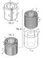
- Figs. 2-6 show steps of making a shell of a thermal shield in accordance with an embodiment of the present invention.
- Fig. 2 shows a thermally conductive wire or cable 70 toroidally wrapped about an annular tool 72.
- the annular tool 72 is lined with a fiberglass cloth 74 to circumferentially reinforce the thermal shield.
- the toroidal wrapping includes wrapping cable 70 about the annular tool 72: (a) axially along an inner surface 76, (b) radially along a first end surface 78 toward an outer surface 80, (c) axially along the outer surface 80, (d) radially along a second end surface 82 toward the inner surface 76, and repeating (a) through (d) circumferentially around the annular tooling 72.
- Cable 70 is positioned about the annular tooling 72 such that heat conduction thermally conducts heat from an inner section 84 of toroidally wrapped cable 70 toward an outer section 86 thereof.
- Fig. 3 shows a thermally conductive wire or cable 88 spirally wrapped over the toroidally wrapped cable 70.
- cables 70, 88 are separate cables; however, it is contemplated that cables 70, 88 are the same cable.
- Cable 88 is circumferentially and spirally wrapped about the outer diameter 86 of toroidally wrapped cable 70. Cable 88 is spirally wrapped such that heat conduction thermally conducts heat toward the axial center 90 of the thermal shield.
- vacuum bag 94 is annular shaped to enclose the wrapped annular tool 92.
- Vacuum bag 94 includes an inner tube wall 96 inserted into a bore 98 of wrapped annular tooling 92 and an outer tube wall 100 placed over an outer surface 102 of wrapped annular tooling 92. Tube walls 96 and 100 are fused together at each end 104, 106 to create a vacuum-tight bag.
- a vacuum 108 is created inside vacuum bag 94.
- the vacuum 108 causes vacuum bag 94 to contract.
- cables 70 and 88 are pressed against the annular tool 72 to take the shape thereof.
- a matrix 110 is infused so as to permeate voids inside vacuum bag 94.
- matrix 110 is an epoxy. The matrix 110 is allowed to cure, and once cured, vacuum bag 94 is removed therefrom.
- a shell 112 formed by cables 70 and 88, fiberglass cloth 74, and matrix 110 is separated into at least two sections 114, 116 and removed from the annular tooling 72 by cutting through the shell along an inner circumference 118 and an outer circumference 120 thereof.
- Fig. 7 shows an exploded view of a thermal shield 122 in accordance with an embodiment of the present invention.
- Shell sections 114, 116 are placed about a cold mass 124 so as to enclose the cold mass 124.
- Shell sections 114, 116 are joined together and connected to a thermal link or central structure 126 including an inner plate 128, a pair of outer metal plates 130, 132 and a plurality of metal blocks 134.
- Outer metal plates 130, 132 are preferably formed of aluminum or copper, and blocks 134 are preferably formed of copper; however, one skilled in the art will appreciate that other materials may be used.
- Outer metal plates 130, 132 are bonded to shell sections 114, 116 to enhance thermal contact between blocks 134 and shell sections 114, 116.
- Fig. 8 shows inner metal plate 128, an outer metal plate 130, and a plurality of metal blocks 134 assembled to a shell section 116.
- Inner metal plate 128 has a plurality of holes 136 formed therein to align with holes 138 formed in each metal block 134.
- Inner plate 128 is positioned adjacent to an inner surface 140 of shell section 116.
- An outer surface 142 of shell section 116 has outer metal plate 132 positioned adjacent thereto.
- a plurality of metal blocks 134 are positioned adjacent to the outer metal plate 132 and secured to the inner plate 128.
- the plurality of metal blocks 134 are bolted to the inner plate 128.
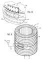
- Fig. 9 shows an assembled thermal shield 122.
- a cryogenic cold head 144 is shown schematically attached to the plurality of metal blocks 134.
- a plurality of copper braids 146 are thermally connected to the cryogenic cold head 144 and to the plurality of metal blocks 134.
- Heat generated in thermal shield 122 is conducted toward the plurality of metal blocks 134 via cables 70, 88. The heat is further conducted toward the cold head via the plurality of copper braids 146.
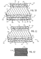
- Fig. 10 shows a cross sectional view taken along line 10-10 of Fig. 5.
- Matrix 110 infused in vacuum bag 94 fills voids 148 between fiberglass cloth 74, cables 70, 88 and vacuum bag 94.
- Fig. 11 shows a cross sectional view taken along line 11-11 of Fig. 9.
- Thermal shield 122 surrounds cold mass 124 to intercept radiation and conduction heat loads thereto.
- an inside wall 150 of thermal shield 122 has a layer of axially wrapped cables 70 while an outside wall 152 of thermal shield 122 has a layer of axially wrapped cables 70 and a layer of spirally wrapped cables 88.
- Fig. 12 shows a preferred arrangement for cables 70, 88.
- Cables 70, 88 are preferably constructed of a plurality of fibers or strands 154 braided together in a Litz wire configuration.
- Strands 154 are preferably constructed of aluminum or copper and are electrically insulated from one another. In this manner, each strand 154 acts individually in generating eddy currents and AC losses.
- Cables 70, 88 constructed of the Litz wire configuration shown in Fig. 12 have reduced eddy currents and AC losses in an AC field than in a single strand cable of equal diameter.
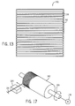
- Figs. 13-15 show steps of making a thermal shield in accordance with an embodiment of the present invention.
- Fig. 13 shows a shell 156 of a thermal shield in accordance with an embodiment of the present invention.
- a plurality of cables 158 are laid onto a flat, flexible sheet 160 with adhesives.
- Sheet 160 is preferably a thin (G10) fiberglass sheet.
- shell 156 is placed on a tooling form 162 defining a desired shape.
- another shell 164 having a sheet 166 and a plurality of cables 168 is positioned adjacent to shell 156.
- the plurality of cables 168 of shell 164 are preferably oriented 90 degrees with respect to the plurality of cables 158 of shell 156.
- a matrix 170 is then infused and cured about shells 156, 164 to bond them together.
- a vacuum bag (not shown) may be used as described above in Fig. 4 and 5 for matrix 170 infusion and curing.
- Fig. 15 shows a thermal shield 172 positionable around a cold mass (not shown) in accordance with an embodiment of the present invention.
- a central structure 126 as described above, is attached to an end 174 of bonded shells 156, 164 and is thermally connected to a cryogenic cold head 176.
- Fig. 16 shows a cross sectional view taken along line 16-16 of Fig. 15.
- Shells 156, 164 encircle axially wrapped cables 158, circumferentially wrapped cables 168, and matrix 170.
- Fig. 17 shows an aspect of making a thermal shield in accordance with an embodiment of the present invention.
- a motor 178 attached to a shaft 180 rotates a drum 182 having a cable 184 spirally wrapped therearound. Cable 184 passes through an matrix bath 186 and is wet wound onto rotating drum 182 while being simultaneously translated axially along drum 182.
- the matrix bath 186 preferably includes epoxy. Following wet winding of the matrix coated cable 184 onto drum 182, the matrix coated cable 184 is allowed to cure to form a shell (not shown) and is removed from drum 182.
- a central structure (not shown), as described above, is attached to the shell, and the shell is positioned about a cold mass (not shown).
- a thermal shield according to an embodiment of the present invention reduces heat generated by eddy currents and reduces AC losses. Furthermore, during a magnet quench, as the current of the magnet coil rapidly decays to zero, eddy currents and quench forces induced in the thermal shield will be minimized, thus allowing the thermal shield to withstand the quench forces.
- an apparatus includes a cryogenic cold head and a plurality of thermally conducting fibers positioned along a desired direction of heat conduction, each fiber electrically insulated from another fiber. A matrix bonding the plurality of thermally conducting fibers together is included. The apparatus also includes at least one thermal link connecting the plurality of thermally conducting fibers to the cryogenic cold head.
- the present invention may also be embodied in a method of manufacturing a thermal shield that includes positioning at least one thermally conducting fiber on a tooling form along a desired path of heat conduction, the at least one thermally conducting fiber coated with electrical insulation. The method further includes fixing the at least one thermally conducting fiber with a matrix and thermally connecting the at least one thermally conducting fiber to a cryogenic cold head.
- An MRI apparatus includes a magnetic resonance imaging system having a plurality of gradient coils positioned about a bore of a superconducting magnet to impress a polarizing magnetic field and an RF transceiver system and an RF switch controlled by a pulse module to transmit RF signals to an RF coil assembly to acquire MR images.
- the MRI apparatus also includes a cryogenic cold head and a thermal link thermally connected to the cryogenic cold head.
- the apparatus further includes a thermal shield positioned adjacent to the superconducting magnet, the thermal shield comprising a set of electrically insulated wires thermally attached to the thermal link and configured to conduct heat to the thermal shield.
- a matrix is included affixing the set of electrically insulated wires together.
Landscapes
- Physics & Mathematics (AREA)
- Condensed Matter Physics & Semiconductors (AREA)
- General Physics & Mathematics (AREA)
- Electromagnetism (AREA)
- Magnetic Resonance Imaging Apparatus (AREA)
Abstract
Description
- The invention relates generally to superconducting magnet systems and more particularly to low AC loss thermal shields of a superconducting magnet system.
- In one example, an MR system includes a cold mass that comprises a superconducting magnet, a magnet coil support structure, and a helium vessel. Liquid helium contained in the helium vessel provides cooling for the superconducting magnet and maintains the superconducting magnet at a low temperature for superconducting operations, as will be understood by those skilled in the art. The liquid helium maintains the superconducting magnet approximately and/or substantially at the liquid helium temperature of 4.2 Kelvin (K). For thermal isolation, the helium vessel that contains the liquid helium in one example comprises one or more thermal shields and a vacuum vessel.
- The vacuum vessel maintains a vacuum environment that eliminates convection heat loads. The thermal shield intercepts radiation and conduction heat loads to the cold mass. Conventional thermal shields are made of conductive metals such as copper or aluminum. The thermal shield is cooled to an intermediate temperature between 4.2 K and the room temperature by a cryocooler or some cryogen such as the liquid nitrogen. It completely surrounds the 4.2 K cold mass to block radiation heat from the room temperature vacuum vessel to the cold mass. Good thermal conduction is required for the thermal shield to make its temperature as low as possible. When the magnet is operated in an AC field, such as during MR imaging, eddy currents will be induced in the thermal shield components. The eddy current generates heat in the thermal shield that must be removed by the cryogenic system. Also, during a magnet quench, as the current of the magnet coil rapidly decays to zero, large eddy currents and quench forces will be induced in the thermal shield. It is difficult for the thermal shield to withstand the quench forces. It is also difficult to structurally support the thermal shield under the quench forces.
- It would therefore be desirable to have an apparatus configured to reduce quench forces and eddy currents generated by ac fields in the thermal shield.
- In one embodiment the present invention provides an apparatus for reducing AC losses that addresses the aforementioned drawbacks. A plurality of thermally conducting fibers are positioned along a desired direction of heat conduction. Each fiber is electrically insulated from another fiber. The fibers are bonded together with a matrix, and a thermal link connects the bonded fibers to a cryogenic cold head.
- In accordance with one aspect of the invention, an apparatus includes a cryogenic cold head and a plurality of thermally conducting fibers positioned along a desired direction of heat conduction, each fiber electrically insulated from another fiber. A matrix bonding the plurality of thermally conducting fibers together is included. The apparatus also includes at least one thermal link connecting the plurality of thermally conducting fibers to the cryogenic cold head.
- In accordance with another aspect of the invention, a method of manufacturing a thermal shield includes positioning at least one thermally conducting fiber on a tooling form along a desired path of heat conduction, the at least on thermally conducting fiber coated with electrical insulation. The method further includes fixing the at least one thermally conducting fiber with a matrix and thermally connecting the at least one thermally conducting fiber to a cryogenic cold head.
- In accordance with yet another aspect of the invention, an MRI apparatus includes a magnetic resonance imaging system having a plurality of gradient coils positioned about a bore of a superconducting magnet to impress a polarizing magnetic field and an RF transceiver system and an RF switch controlled by a pulse module to transmit RF signals to an RF coil assembly to acquire MR images. The MRI apparatus also includes a cryogenic cold head and a thermal link thermally connected to the cryogenic cold head. The apparatus further includes a thermal shield positioned adjacent to the superconducting magnet, the thermal shield comprising a set of electrically insulated wires thermally attached to the thermal link and configured to conduct heat to the thermal shield. A matrix is included affixing the set of electrically insulated wires together.
- Various features and advantages of the present invention will be made apparent from the following detailed description and the drawings, in which:
- Fig. 1 is a schematic block diagram of an MR imaging system that can benefit from incorporation of an embodiment of the present invention.
- Figs. 2-6 show steps of making a shell of thermal shield in accordance with an embodiment of the present invention.
- Fig. 7 is an exploded view of a thermal shield in accordance with an embodiment of the present invention.
- Fig. 8 is a perspective view of a partial assembly of the thermal shield of Fig. 7.
- Fig. 9 is a perspective view of the thermal shield of Fig. 7 in assembled form.
- Fig. 10 is a cross sectional view taken along line 10-10 of Fig. 5.
- Fig. 11 is a cross sectional view taken along line 11-11 of Fig. 9.
- Fig. 12 is a preferred arrangement for thermally conductive cables in accordance with an embodiment of the present invention.
- Figs. 13-15 show steps of making a thermal shield in accordance with an embodiment of the present invention.
- Fig. 16 is a cross sectional view taken along line 16-16 of Fig. 15.
- Fig. 17 shows a step of making a shell of thermal shield in accordance with an embodiment of the present invention.
- Referring to Fig. 1, the major components of a preferred magnetic resonance imaging (MRI)
system 10 benefiting from incorporating an embodiment of the present invention are shown. The operation of thesystem 10 is controlled from anoperator console 12, which includes a keyboard orother input device 13, acontrol panel 14, and adisplay screen 16. Theconsole 12 communicates through alink 18 with aseparate computer system 20 that enables an operator to control the production and display of images on thedisplay screen 16. Thecomputer system 20 includes a number of modules which communicate with each other through a backplane 20a. These include animage processor module 22, aCPU module 24 and amemory module 26, known in the art as a frame buffer for storing image data arrays. Thecomputer system 20 is linked todisk storage 28 andtape drive 30 for storage of image data and programs, and communicates with aseparate system control 32 through a highspeed serial link 34. Theinput device 13 can include a mouse, joystick, keyboard, track ball, touch activated screen, light wand, voice control, or any similar or equivalent input device, and may be used for interactive geometry prescription. - The
system control 32 includes a set of modules connected together by abackplane 32a. These include aCPU module 36 and apulse generator module 38 which connects to theoperator console 12 through aserial link 40. It is throughlink 40 that thesystem control 32 receives commands from the operator to indicate the scan sequence that is to be performed. Thepulse generator module 38 operates the system components to carry out the desired scan sequence and produces data which indicates the timing, strength and shape of the RF pulses produced, and the timing and length of the data acquisition window. Thepulse generator module 38 connects to a set ofgradient amplifiers 42, to indicate the timing and shape of the gradient pulses that are produced during the scan. Thepulse generator module 38 can also receive patient data from aphysiological acquisition controller 44 that receives signals from a number of different sensors connected to the patient, such as ECG signals from electrodes attached to the patient. And finally, thepulse generator module 38 connects to a scanroom interface circuit 46 which receives signals from various sensors associated with the condition of the patient and the magnet system. It is also through the scanroom interface circuit 46 that apatient positioning system 48 receives commands to move the patient to the desired position for the scan. - The gradient waveforms produced by the
pulse generator module 38 are applied to thegradient amplifier system 42 having Gx, Gy, and Gz amplifiers. Each gradient amplifier excites a corresponding physical gradient coil in a gradient coil assembly generally designated 50 to produce the magnetic field gradients used for spatially encoding acquired signals. Thegradient coil assembly 50 forms part of amagnet assembly 52 which includes a polarizingmagnet 54 and a whole-body RF coil 56. Atransceiver module 58 in thesystem control 32 produces pulses which are amplified by anRF amplifier 60 and coupled to theRF coil 56 by a transmit/receiveswitch 62. The resulting signals emitted by the excited nuclei in the patient may be sensed by thesame RF coil 56 and coupled through the transmit/receiveswitch 62 to apreamplifier 64. The amplified MR signals are demodulated, filtered, and digitized in the receiver section of thetransceiver 58. The transmit/receive switch 62 is controlled by a signal from thepulse generator module 38 to electrically connect theRF amplifier 60 to thecoil 56 during the transmit mode and to connect thepreamplifier 64 to thecoil 56 during the receive mode. The transmit/receiveswitch 62 can also enable a separate RF coil (for example, a surface coil) to be used in either the transmit or receive mode. - The MR signals picked up by the
RF coil 56 are digitized by thetransceiver module 58 and transferred to amemory module 66 in thesystem control 32. A scan is complete when an array of raw k-space data has been acquired in thememory module 66. This raw k-space data is rearranged into separate k-space data arrays for each image to be reconstructed, and each of these is input to anarray processor 68 which operates to Fourier transform the data into an array of image data. This image data is conveyed through theserial link 34 to thecomputer system 20 where it is stored in memory, such asdisk storage 28. In response to commands received from theoperator console 12, this image data may be archived in long term storage, such as on thetape drive 30, or it may be further processed by theimage processor 22 and conveyed to theoperator console 12 and presented on thedisplay 16. - Figs. 2-6 show steps of making a shell of a thermal shield in accordance with an embodiment of the present invention. Fig. 2 shows a thermally conductive wire or
cable 70 toroidally wrapped about anannular tool 72. In a preferred embodiment, theannular tool 72 is lined with afiberglass cloth 74 to circumferentially reinforce the thermal shield. The toroidal wrapping includes wrappingcable 70 about the annular tool 72: (a) axially along aninner surface 76, (b) radially along afirst end surface 78 toward anouter surface 80, (c) axially along theouter surface 80, (d) radially along asecond end surface 82 toward theinner surface 76, and repeating (a) through (d) circumferentially around theannular tooling 72.Cable 70 is positioned about theannular tooling 72 such that heat conduction thermally conducts heat from aninner section 84 of toroidally wrappedcable 70 toward anouter section 86 thereof. - Fig. 3 shows a thermally conductive wire or
cable 88 spirally wrapped over the toroidally wrappedcable 70. Preferably,cables cables Cable 88 is circumferentially and spirally wrapped about theouter diameter 86 of toroidally wrappedcable 70.Cable 88 is spirally wrapped such that heat conduction thermally conducts heat toward theaxial center 90 of the thermal shield. - After
cables annular tool 92 is placed inside avacuum bag 94 as shown in Fig. 4. In a preferred embodiment,vacuum bag 94 is annular shaped to enclose the wrappedannular tool 92.Vacuum bag 94 includes aninner tube wall 96 inserted into abore 98 of wrappedannular tooling 92 and anouter tube wall 100 placed over anouter surface 102 of wrappedannular tooling 92.Tube walls end 104, 106 to create a vacuum-tight bag. - As shown in Fig. 5, a
vacuum 108 is created insidevacuum bag 94. Thevacuum 108 causesvacuum bag 94 to contract. In this manner,cables annular tool 72 to take the shape thereof. Once avacuum 108 has been created insidevacuum bag 94, amatrix 110 is infused so as to permeate voids insidevacuum bag 94. In a preferred embodiment,matrix 110 is an epoxy. Thematrix 110 is allowed to cure, and once cured,vacuum bag 94 is removed therefrom. - Referring to Fig. 6, a
shell 112 formed bycables fiberglass cloth 74, andmatrix 110 is separated into at least twosections annular tooling 72 by cutting through the shell along aninner circumference 118 and anouter circumference 120 thereof. - Fig. 7 shows an exploded view of a
thermal shield 122 in accordance with an embodiment of the present invention.Shell sections cold mass 124 so as to enclose thecold mass 124.Shell sections central structure 126 including aninner plate 128, a pair ofouter metal plates Outer metal plates Outer metal plates sections blocks 134 andshell sections - Fig. 8 shows
inner metal plate 128, anouter metal plate 130, and a plurality ofmetal blocks 134 assembled to ashell section 116.Inner metal plate 128 has a plurality ofholes 136 formed therein to align withholes 138 formed in eachmetal block 134.Inner plate 128 is positioned adjacent to aninner surface 140 ofshell section 116. Anouter surface 142 ofshell section 116 hasouter metal plate 132 positioned adjacent thereto. A plurality ofmetal blocks 134 are positioned adjacent to theouter metal plate 132 and secured to theinner plate 128. Preferably, the plurality ofmetal blocks 134 are bolted to theinner plate 128. - Fig. 9 shows an assembled
thermal shield 122. A cryogeniccold head 144 is shown schematically attached to the plurality of metal blocks 134. A plurality ofcopper braids 146 are thermally connected to the cryogeniccold head 144 and to the plurality of metal blocks 134. Heat generated inthermal shield 122 is conducted toward the plurality ofmetal blocks 134 viacables - Fig. 10 shows a cross sectional view taken along line 10-10 of Fig. 5.
Matrix 110 infused invacuum bag 94 fillsvoids 148 betweenfiberglass cloth 74,cables vacuum bag 94. Fig. 11 shows a cross sectional view taken along line 11-11 of Fig. 9.Thermal shield 122 surroundscold mass 124 to intercept radiation and conduction heat loads thereto. As shown in Figs. 10 and 11, aninside wall 150 ofthermal shield 122 has a layer of axially wrappedcables 70 while anoutside wall 152 ofthermal shield 122 has a layer of axially wrappedcables 70 and a layer of spirally wrappedcables 88. - Fig. 12 shows a preferred arrangement for
cables Cables strands 154 braided together in a Litz wire configuration.Strands 154 are preferably constructed of aluminum or copper and are electrically insulated from one another. In this manner, eachstrand 154 acts individually in generating eddy currents and AC losses.Cables - Figs. 13-15 show steps of making a thermal shield in accordance with an embodiment of the present invention. Fig. 13 shows a
shell 156 of a thermal shield in accordance with an embodiment of the present invention. A plurality ofcables 158 are laid onto a flat,flexible sheet 160 with adhesives.Sheet 160 is preferably a thin (G10) fiberglass sheet. - As shown in Fig. 14,
shell 156 is placed on atooling form 162 defining a desired shape. In a preferred embodiment, anothershell 164 having asheet 166 and a plurality ofcables 168 is positioned adjacent to shell 156. The plurality ofcables 168 ofshell 164 are preferably oriented 90 degrees with respect to the plurality ofcables 158 ofshell 156. Amatrix 170 is then infused and cured aboutshells matrix 170 infusion and curing. - Fig. 15 shows a
thermal shield 172 positionable around a cold mass (not shown) in accordance with an embodiment of the present invention. Acentral structure 126, as described above, is attached to anend 174 of bondedshells - Fig. 16 shows a cross sectional view taken along line 16-16 of Fig. 15.
Shells cables 158, circumferentially wrappedcables 168, andmatrix 170. - Fig. 17 shows an aspect of making a thermal shield in accordance with an embodiment of the present invention. A
motor 178 attached to ashaft 180 rotates adrum 182 having acable 184 spirally wrapped therearound.Cable 184 passes through anmatrix bath 186 and is wet wound ontorotating drum 182 while being simultaneously translated axially alongdrum 182. Thematrix bath 186 preferably includes epoxy. Following wet winding of the matrix coatedcable 184 ontodrum 182, the matrix coatedcable 184 is allowed to cure to form a shell (not shown) and is removed fromdrum 182. A central structure (not shown), as described above, is attached to the shell, and the shell is positioned about a cold mass (not shown). - A thermal shield according to an embodiment of the present invention reduces heat generated by eddy currents and reduces AC losses. Furthermore, during a magnet quench, as the current of the magnet coil rapidly decays to zero, eddy currents and quench forces induced in the thermal shield will be minimized, thus allowing the thermal shield to withstand the quench forces.
- Therefore, an apparatus is disclosed and includes a cryogenic cold head and a plurality of thermally conducting fibers positioned along a desired direction of heat conduction, each fiber electrically insulated from another fiber. A matrix bonding the plurality of thermally conducting fibers together is included. The apparatus also includes at least one thermal link connecting the plurality of thermally conducting fibers to the cryogenic cold head.
- The present invention may also be embodied in a method of manufacturing a thermal shield that includes positioning at least one thermally conducting fiber on a tooling form along a desired path of heat conduction, the at least one thermally conducting fiber coated with electrical insulation. The method further includes fixing the at least one thermally conducting fiber with a matrix and thermally connecting the at least one thermally conducting fiber to a cryogenic cold head.
- An MRI apparatus is also presented and includes a magnetic resonance imaging system having a plurality of gradient coils positioned about a bore of a superconducting magnet to impress a polarizing magnetic field and an RF transceiver system and an RF switch controlled by a pulse module to transmit RF signals to an RF coil assembly to acquire MR images. The MRI apparatus also includes a cryogenic cold head and a thermal link thermally connected to the cryogenic cold head. The apparatus further includes a thermal shield positioned adjacent to the superconducting magnet, the thermal shield comprising a set of electrically insulated wires thermally attached to the thermal link and configured to conduct heat to the thermal shield. A matrix is included affixing the set of electrically insulated wires together.
- The present invention has been described in terms of the preferred embodiments, and it is recognized that equivalents, alternatives, and modifications, aside from those expressly stated, are possible and within the scope of the appending claims.
-
10 preferred MR system 12 operator console 13 keyboard or other input device 14 control panel 16 display screen 18 link 20 separate computer system 20a backplane 22 image processor module 24 CPU module 26 memory module 28 disk storage 30 tape drive 32 separate system control 32a backplane 34 high speed serial link 36 CPU module 38 pulse generator module 40 serial link 42 set of gradient amplifiers 44 physiological acquisition controller 46 scan room interface circuit 48 object positioning system 50 gradient coil assembly 52 magnet assembly 54 polarizing magnet 56 whole-body RF coil 58 transceiver module 60 RF amplifier 62 transmit/receive switch 64 preamplifier 66 memory module 68 array processor 70 cable 72 annular tooling 74 fiberglass cloth 76 inner surface 78 first end surface 80 outer surface 82 second end surface 84 inner section 86 outer section 88 cable 90 axial center 92 wrapped annular tooling 94 vacuum bag 96 inner tube wall 98 bore 100 outer tube wall 102 outer surface 104 end 106 end 108 vacuum 110 epoxy 112 shell 114 shell section 116 shell section 118 inner circumference 120 outer circumference 122 thermal shield 124 cold mass 126 central structure 128 inner metal plate 130 outer metal plate 132 outer metal plate 134 plurality of metal blocks 136 plurality of holes 138 hole 140 inner surface 142 outer surface 144 cryogenic cold head 146 plurality of copper braids 148 voids 150 inside wall 152 outside wall 154 strands 156 shell 158 plurality of cables 160 sheet 162 tooling form 164 shell 166 sheet 168 plurality of cables 170 epoxy 172 thermal shield 174 end 176 cryogenic cold head 178 motor 180 shaft 182 drum 184 cable 186 epoxy bath
Claims (10)
- An apparatus comprising:a cryogenic cold head (144);a plurality of thermally conducting fibers (70, 88, 158, 168, 184) positioned along a desired direction of heat conduction, each fiber (70, 88, 158, 168, 184) electrically insulated from another fiber (70, 88, 158, 168, 184);a matrix (110, 170) bonding the plurality of thermally conducting fibers (70, 88, 158, 168, 184) together; andat least one thermal link (126) connecting the plurality of thermally conducting fibers (70, 88, 158, 168, 184) to the cryogenic cold head (144).
- The apparatus of claim 1 wherein the plurality of thermally conducting fibers (70, 88, 158, 168, 184) comprise copper.
- The apparatus of claim 1 or claim 2 wherein the plurality of thermally conducting fibers (70, 88, 158, 168, 184) comprise aluminum.
- The apparatus of any preceding claim wherein the bonded plurality of thermally conducting fibers (70, 88, 158, 168, 184) form a shell (112, 156, 164) configured to encircle a superconducting magnet (124).
- The apparatus of claim 4 wherein the shell (112, 156, 164) is further configured to surround the superconducting magnet (124).
- The apparatus of any preceding claim further comprising a flexible sheet (160, 166), wherein the matrix (110, 170) bonds the flexible sheet (160, 166) to the plurality of thermally conducting fibers (70, 88, 158, 168, 184).
- The apparatus of any preceding claim wherein the matrix (110, 170) comprises epoxy.
- The apparatus of claim 6 or claim 7 when dependent thereon wherein the flexible sheet (160, 166) comprises fiberglass.
- The apparatus of any preceding claim wherein the plurality of thermally conducting fibers (70, 88, 158, 168, 184) are wound together in a Litz wire configuration.
- The apparatus of any preceding claim further comprising an MR imaging apparatus (10).
Applications Claiming Priority (1)
| Application Number | Priority Date | Filing Date | Title |
|---|---|---|---|
| US11/461,544 US7852079B2 (en) | 2006-08-01 | 2006-08-01 | Apparatus for low AC loss thermal shielding and method of making same |
Publications (2)
| Publication Number | Publication Date |
|---|---|
| EP1887374A1 true EP1887374A1 (en) | 2008-02-13 |
| EP1887374B1 EP1887374B1 (en) | 2010-04-14 |
Family
ID=38666920
Family Applications (1)
| Application Number | Title | Priority Date | Filing Date |
|---|---|---|---|
| EP07113170A Not-in-force EP1887374B1 (en) | 2006-08-01 | 2007-07-26 | Apparatus comprising means for low ac loss thermal shielding |
Country Status (5)
| Country | Link |
|---|---|
| US (1) | US7852079B2 (en) |
| EP (1) | EP1887374B1 (en) |
| JP (1) | JP5058702B2 (en) |
| CN (1) | CN101127270B (en) |
| DE (1) | DE602007005885D1 (en) |
Families Citing this family (5)
| Publication number | Priority date | Publication date | Assignee | Title |
|---|---|---|---|---|
| US7852079B2 (en) * | 2006-08-01 | 2010-12-14 | General Electric Company | Apparatus for low AC loss thermal shielding and method of making same |
| US8570043B2 (en) * | 2010-10-05 | 2013-10-29 | General Electric Company | System and method for self-sealing a coldhead sleeve of a magnetic resonance imaging system |
| CN104599805B (en) * | 2015-01-30 | 2017-01-25 | 中国科学院电工研究所 | A Strong Magnetic Focusing Magnet System for a Terahertz Source |
| CN107229025A (en) * | 2016-03-24 | 2017-10-03 | 西门子(深圳)磁共振有限公司 | The heat shielding cover and MR imaging apparatus of MR imaging apparatus |
| EP4650808A1 (en) * | 2024-05-15 | 2025-11-19 | Koninklijke Philips N.V. | Magnet assembly for use in a magnetic resonance examination system |
Citations (5)
| Publication number | Priority date | Publication date | Assignee | Title |
|---|---|---|---|---|
| EP0228683A2 (en) | 1986-01-03 | 1987-07-15 | General Electric Company | A low cost intermediate radiation shield for a magnet cryostat |
| JPH0582333A (en) * | 1991-09-19 | 1993-04-02 | Hitachi Ltd | Nuclear magnetic resonance diagnostic device |
| US5225782A (en) | 1991-09-13 | 1993-07-06 | General Electric Company | Eddy current free MRI magnet with integrated gradient coils |
| JPH05172924A (en) * | 1991-12-25 | 1993-07-13 | Hitachi Ltd | Invasion heat measuring device for cryostat |
| US5446433A (en) * | 1994-09-21 | 1995-08-29 | General Electric Company | Superconducting magnet having a shock-resistant support structure |
Family Cites Families (9)
| Publication number | Priority date | Publication date | Assignee | Title |
|---|---|---|---|---|
| JPH0793205B2 (en) * | 1986-01-17 | 1995-10-09 | 三菱電機株式会社 | Cryogenic device |
| US5280247A (en) * | 1992-03-27 | 1994-01-18 | Picker International, Inc. | Filamentary cold shield for superconducting magnets |
| US6783059B2 (en) | 2002-12-23 | 2004-08-31 | General Electric Company | Conduction cooled passively-shielded MRI magnet |
| CN2720778Y (en) * | 2004-08-10 | 2005-08-24 | 宁波市北仑海伯精密机械制造有限公司 | Super-conductive conduit |
| US7187169B2 (en) * | 2004-11-03 | 2007-03-06 | The Regents Of The University Of California | NMR and MRI apparatus and method |
| US7319329B2 (en) * | 2005-11-28 | 2008-01-15 | General Electric Company | Cold mass with discrete path substantially conductive coupler for superconducting magnet and cryogenic cooling circuit |
| US7626477B2 (en) * | 2005-11-28 | 2009-12-01 | General Electric Company | Cold mass cryogenic cooling circuit inlet path avoidance of direct conductive thermal engagement with substantially conductive coupler for superconducting magnet |
| US7852079B2 (en) * | 2006-08-01 | 2010-12-14 | General Electric Company | Apparatus for low AC loss thermal shielding and method of making same |
| JP5539889B2 (en) * | 2007-10-23 | 2014-07-02 | アブクマー インコーポレイテッド | Micro coil magnetic resonance detector |
-
2006
- 2006-08-01 US US11/461,544 patent/US7852079B2/en not_active Expired - Fee Related
-
2007
- 2007-07-26 EP EP07113170A patent/EP1887374B1/en not_active Not-in-force
- 2007-07-26 DE DE602007005885T patent/DE602007005885D1/en not_active Expired - Fee Related
- 2007-07-26 JP JP2007194125A patent/JP5058702B2/en not_active Expired - Fee Related
- 2007-08-01 CN CN2007101384140A patent/CN101127270B/en not_active Expired - Fee Related
Patent Citations (5)
| Publication number | Priority date | Publication date | Assignee | Title |
|---|---|---|---|---|
| EP0228683A2 (en) | 1986-01-03 | 1987-07-15 | General Electric Company | A low cost intermediate radiation shield for a magnet cryostat |
| US5225782A (en) | 1991-09-13 | 1993-07-06 | General Electric Company | Eddy current free MRI magnet with integrated gradient coils |
| JPH0582333A (en) * | 1991-09-19 | 1993-04-02 | Hitachi Ltd | Nuclear magnetic resonance diagnostic device |
| JPH05172924A (en) * | 1991-12-25 | 1993-07-13 | Hitachi Ltd | Invasion heat measuring device for cryostat |
| US5446433A (en) * | 1994-09-21 | 1995-08-29 | General Electric Company | Superconducting magnet having a shock-resistant support structure |
Also Published As
| Publication number | Publication date |
|---|---|
| CN101127270B (en) | 2012-04-25 |
| DE602007005885D1 (en) | 2010-05-27 |
| CN101127270A (en) | 2008-02-20 |
| EP1887374B1 (en) | 2010-04-14 |
| JP2008036421A (en) | 2008-02-21 |
| US20100237868A1 (en) | 2010-09-23 |
| JP5058702B2 (en) | 2012-10-24 |
| US7852079B2 (en) | 2010-12-14 |
Similar Documents
| Publication | Publication Date | Title |
|---|---|---|
| US20070120630A1 (en) | Cold mass cryogenic cooling circuit inlet path avoidance of direct conductive thermal engagement with substantially conductive coupler for superconducting magnet | |
| US7319329B2 (en) | Cold mass with discrete path substantially conductive coupler for superconducting magnet and cryogenic cooling circuit | |
| EP1918948B1 (en) | High temperature superconducting current leads for superconduction magnets | |
| CN101614797B (en) | System and apparatus for providing electrical and cooling interconnections in magnetic resonance imaging (MRI) system | |
| JP4686588B2 (en) | Magnet assembly for magnetic resonance imaging system | |
| US7962019B2 (en) | System, method and apparatus for controlling drift of a main magnetic field in an MRI system | |
| US20140167757A1 (en) | Vacuum feed-through assembly | |
| US8890529B2 (en) | System and apparatus for providing interconnections in a gradient coil assembly | |
| US9810755B2 (en) | System and method for energizing a superconducting magnet | |
| JP5307354B2 (en) | Cable and method of manufacturing the cable | |
| EP1887374B1 (en) | Apparatus comprising means for low ac loss thermal shielding | |
| US20140155268A1 (en) | System and apparatus for compensating for magnetic field distortion in an mri system | |
| CN101093248B (en) | Method and apparatus for locally shielding MR superconducting magnet coil | |
| JP6061518B2 (en) | System and apparatus for balancing radial forces in gradient coils | |
| JP5020699B2 (en) | Low AC loss single filament superconductor for superconducting magnet and method of manufacturing |
Legal Events
| Date | Code | Title | Description |
|---|---|---|---|
| PUAI | Public reference made under article 153(3) epc to a published international application that has entered the european phase |
Free format text: ORIGINAL CODE: 0009012 |
|
| AK | Designated contracting states |
Kind code of ref document: A1 Designated state(s): AT BE BG CH CY CZ DE DK EE ES FI FR GB GR HU IE IS IT LI LT LU LV MC MT NL PL PT RO SE SI SK TR |
|
| AX | Request for extension of the european patent |
Extension state: AL BA HR MK YU |
|
| 17P | Request for examination filed |
Effective date: 20080813 |
|
| 17Q | First examination report despatched |
Effective date: 20080918 |
|
| AKX | Designation fees paid |
Designated state(s): DE GB NL |
|
| RTI1 | Title (correction) |
Free format text: APPARATUS COMPRISING MEANS FOR LOW AC LOSS THERMAL SHIELDING |
|
| GRAP | Despatch of communication of intention to grant a patent |
Free format text: ORIGINAL CODE: EPIDOSNIGR1 |
|
| GRAS | Grant fee paid |
Free format text: ORIGINAL CODE: EPIDOSNIGR3 |
|
| GRAA | (expected) grant |
Free format text: ORIGINAL CODE: 0009210 |
|
| AK | Designated contracting states |
Kind code of ref document: B1 Designated state(s): DE GB NL |
|
| REG | Reference to a national code |
Ref country code: GB Ref legal event code: FG4D |
|
| REF | Corresponds to: |
Ref document number: 602007005885 Country of ref document: DE Date of ref document: 20100527 Kind code of ref document: P |
|
| REG | Reference to a national code |
Ref country code: NL Ref legal event code: T3 |
|
| PLBE | No opposition filed within time limit |
Free format text: ORIGINAL CODE: 0009261 |
|
| STAA | Information on the status of an ep patent application or granted ep patent |
Free format text: STATUS: NO OPPOSITION FILED WITHIN TIME LIMIT |
|
| 26N | No opposition filed |
Effective date: 20110117 |
|
| PG25 | Lapsed in a contracting state [announced via postgrant information from national office to epo] |
Ref country code: DE Free format text: LAPSE BECAUSE OF NON-PAYMENT OF DUE FEES Effective date: 20110201 |
|
| REG | Reference to a national code |
Ref country code: DE Ref legal event code: R119 Ref document number: 602007005885 Country of ref document: DE Effective date: 20110201 |
|
| PGFP | Annual fee paid to national office [announced via postgrant information from national office to epo] |
Ref country code: NL Payment date: 20160726 Year of fee payment: 10 |
|
| REG | Reference to a national code |
Ref country code: NL Ref legal event code: MM Effective date: 20170801 |
|
| PG25 | Lapsed in a contracting state [announced via postgrant information from national office to epo] |
Ref country code: NL Free format text: LAPSE BECAUSE OF NON-PAYMENT OF DUE FEES Effective date: 20170801 |
|
| PGFP | Annual fee paid to national office [announced via postgrant information from national office to epo] |
Ref country code: GB Payment date: 20190624 Year of fee payment: 13 |
|
| GBPC | Gb: european patent ceased through non-payment of renewal fee |
Effective date: 20200726 |
|
| PG25 | Lapsed in a contracting state [announced via postgrant information from national office to epo] |
Ref country code: GB Free format text: LAPSE BECAUSE OF NON-PAYMENT OF DUE FEES Effective date: 20200726 |