EP1887212A1 - Intake system structure of V-type internal combustion engine - Google Patents
Intake system structure of V-type internal combustion engine Download PDFInfo
- Publication number
- EP1887212A1 EP1887212A1 EP07012102A EP07012102A EP1887212A1 EP 1887212 A1 EP1887212 A1 EP 1887212A1 EP 07012102 A EP07012102 A EP 07012102A EP 07012102 A EP07012102 A EP 07012102A EP 1887212 A1 EP1887212 A1 EP 1887212A1
- Authority
- EP
- European Patent Office
- Prior art keywords
- electrically
- internal combustion
- combustion engine
- type internal
- bank
- Prior art date
- Legal status (The legal status is an assumption and is not a legal conclusion. Google has not performed a legal analysis and makes no representation as to the accuracy of the status listed.)
- Granted
Links
- 238000002485 combustion reaction Methods 0.000 title claims abstract description 50
- 238000001816 cooling Methods 0.000 claims description 14
- 230000015572 biosynthetic process Effects 0.000 abstract description 3
- 230000005540 biological transmission Effects 0.000 description 5
- 230000002708 enhancing effect Effects 0.000 description 3
- 239000000446 fuel Substances 0.000 description 3
- 238000002347 injection Methods 0.000 description 3
- 239000007924 injection Substances 0.000 description 3
- 230000001965 increasing effect Effects 0.000 description 2
- 238000011144 upstream manufacturing Methods 0.000 description 2
- 230000015556 catabolic process Effects 0.000 description 1
- 239000003566 sealing material Substances 0.000 description 1
- 230000003584 silencer Effects 0.000 description 1
- 239000000725 suspension Substances 0.000 description 1
Images



Classifications
-
- F—MECHANICAL ENGINEERING; LIGHTING; HEATING; WEAPONS; BLASTING
- F02—COMBUSTION ENGINES; HOT-GAS OR COMBUSTION-PRODUCT ENGINE PLANTS
- F02M—SUPPLYING COMBUSTION ENGINES IN GENERAL WITH COMBUSTIBLE MIXTURES OR CONSTITUENTS THEREOF
- F02M35/00—Combustion-air cleaners, air intakes, intake silencers, or induction systems specially adapted for, or arranged on, internal-combustion engines
- F02M35/10—Air intakes; Induction systems
- F02M35/104—Intake manifolds
- F02M35/116—Intake manifolds for engines with cylinders in V-arrangement or arranged oppositely relative to the main shaft
-
- F—MECHANICAL ENGINEERING; LIGHTING; HEATING; WEAPONS; BLASTING
- F02—COMBUSTION ENGINES; HOT-GAS OR COMBUSTION-PRODUCT ENGINE PLANTS
- F02D—CONTROLLING COMBUSTION ENGINES
- F02D11/00—Arrangements for, or adaptations to, non-automatic engine control initiation means, e.g. operator initiated
- F02D11/06—Arrangements for, or adaptations to, non-automatic engine control initiation means, e.g. operator initiated characterised by non-mechanical control linkages, e.g. fluid control linkages or by control linkages with power drive or assistance
- F02D11/10—Arrangements for, or adaptations to, non-automatic engine control initiation means, e.g. operator initiated characterised by non-mechanical control linkages, e.g. fluid control linkages or by control linkages with power drive or assistance of the electric type
-
- F—MECHANICAL ENGINEERING; LIGHTING; HEATING; WEAPONS; BLASTING
- F02—COMBUSTION ENGINES; HOT-GAS OR COMBUSTION-PRODUCT ENGINE PLANTS
- F02D—CONTROLLING COMBUSTION ENGINES
- F02D9/00—Controlling engines by throttling air or fuel-and-air induction conduits or exhaust conduits
- F02D9/08—Throttle valves specially adapted therefor; Arrangements of such valves in conduits
- F02D9/10—Throttle valves specially adapted therefor; Arrangements of such valves in conduits having pivotally-mounted flaps
- F02D9/109—Throttle valves specially adapted therefor; Arrangements of such valves in conduits having pivotally-mounted flaps having two or more flaps
- F02D9/1095—Rotating on a common axis, e.g. having a common shaft
-
- F—MECHANICAL ENGINEERING; LIGHTING; HEATING; WEAPONS; BLASTING
- F02—COMBUSTION ENGINES; HOT-GAS OR COMBUSTION-PRODUCT ENGINE PLANTS
- F02M—SUPPLYING COMBUSTION ENGINES IN GENERAL WITH COMBUSTIBLE MIXTURES OR CONSTITUENTS THEREOF
- F02M35/00—Combustion-air cleaners, air intakes, intake silencers, or induction systems specially adapted for, or arranged on, internal-combustion engines
- F02M35/10—Air intakes; Induction systems
- F02M35/10091—Air intakes; Induction systems characterised by details of intake ducts: shapes; connections; arrangements
- F02M35/10104—Substantially vertically arranged ducts
-
- F—MECHANICAL ENGINEERING; LIGHTING; HEATING; WEAPONS; BLASTING
- F02—COMBUSTION ENGINES; HOT-GAS OR COMBUSTION-PRODUCT ENGINE PLANTS
- F02M—SUPPLYING COMBUSTION ENGINES IN GENERAL WITH COMBUSTIBLE MIXTURES OR CONSTITUENTS THEREOF
- F02M35/00—Combustion-air cleaners, air intakes, intake silencers, or induction systems specially adapted for, or arranged on, internal-combustion engines
- F02M35/10—Air intakes; Induction systems
- F02M35/10242—Devices or means connected to or integrated into air intakes; Air intakes combined with other engine or vehicle parts
- F02M35/10255—Arrangements of valves; Multi-way valves
-
- F—MECHANICAL ENGINEERING; LIGHTING; HEATING; WEAPONS; BLASTING
- F02—COMBUSTION ENGINES; HOT-GAS OR COMBUSTION-PRODUCT ENGINE PLANTS
- F02M—SUPPLYING COMBUSTION ENGINES IN GENERAL WITH COMBUSTIBLE MIXTURES OR CONSTITUENTS THEREOF
- F02M35/00—Combustion-air cleaners, air intakes, intake silencers, or induction systems specially adapted for, or arranged on, internal-combustion engines
- F02M35/16—Combustion-air cleaners, air intakes, intake silencers, or induction systems specially adapted for, or arranged on, internal-combustion engines characterised by use in vehicles
- F02M35/162—Motorcycles; All-terrain vehicles, e.g. quads, snowmobiles; Small vehicles, e.g. forklifts
-
- F—MECHANICAL ENGINEERING; LIGHTING; HEATING; WEAPONS; BLASTING
- F02—COMBUSTION ENGINES; HOT-GAS OR COMBUSTION-PRODUCT ENGINE PLANTS
- F02D—CONTROLLING COMBUSTION ENGINES
- F02D41/00—Electrical control of supply of combustible mixture or its constituents
- F02D41/008—Controlling each cylinder individually
- F02D41/0082—Controlling each cylinder individually per groups or banks
Definitions
- the present invention relates to an intake system structure of an internal combustion engine, and more particularly to an intake system structure which includes an electrically-operated actuator for driving a throttle valve in the inside of a throttle body which is provided to an intake system.
- the V-shaped space which is sandwiched between two banks is a space in which various kinds of auxiliary equipments or the like of the internal combustion engine are arranged. Accordingly, in an attempt to arrange the electrically-operated actuator for driving the throttle valve in the space, it is necessary to take a measure which does not impose restriction on the arrangement of the auxiliary equipments. Further, the V-shaped space is sandwiched between two heated banks and hence, the V-shaped space is liable to be easily filled with hot air. Accordingly, it is necessary to take a measure to prevent the electrically-operated actuator, especially, a drive motor of the electrically-operated actuator from being thermally influenced by the hot air thus enhancing the durability thereof.
- the intake system structure described in the patent document JP-A-2002-256900 fails to take the above-mentioned measure into consideration.
- the present invention has been made under such circumstances and it is an object of the present invention to provide a novel intake system structure of a V-type internal combustion engine which can ensure a space for arranging existing auxiliary equipments or the like in a V-shaped space and can enhance the cooling property of an electrically-operated actuator thus enhancing the durability of the electrically-operated actuator.
- the invention described in claim 1 is directed to an intake system structure of a V-type internal combustion engine in which the intake system structure includes front and rear banks, cylinder axes of the cylinders formed on the respective banks exhibit a V shape as viewed in the direction of a crankshaft, front and rear intake ports which are formed in the respective front and rear banks are respectively communicably connected with an intake system which is arranged in a V-shaped space defined between the banks, and the intake system includes front and rear throttle bodies which mount front and rear throttle valves thereon and electrically-operated actuators for driving the throttle valves, wherein the electrically-operated actuators are respectively arranged between cylinder heads of the front and rear banks and the front and rear throttle bodies.
- the invention described in claim 2 is, in the invention described in claim 1, characterized in that the V-type internal combustion engine is a 4-cylinder engine which mounts two cylinders on the front and rear banks respectively, and in a state that the V-type internal combustion engine is mounted on a vehicle, a crankshaft of the V-type internal combustion engine is arranged orthogonal to the advancing direction of the vehicle, and a plurality of electrically-operated actuators are mounted on the front bank which is positioned on a front side in the advancing direction of the vehicle.
- the V-type internal combustion engine is a 4-cylinder engine which mounts two cylinders on the front and rear banks respectively, and in a state that the V-type internal combustion engine is mounted on a vehicle, a crankshaft of the V-type internal combustion engine is arranged orthogonal to the advancing direction of the vehicle, and a plurality of electrically-operated actuators are mounted on the front bank which is positioned on a front side in the advancing direction of the vehicle.
- the invention described in claim 3 is, in the invention described in claim 1, characterized in that the V-type internal combustion engine is a 4-cylinder engine which mounts two cylinders on the front and rear banks respectively, and in a state that the V-type internal combustion engine is mounted on a vehicle, a crankshaft of the V-type internal combustion engine is arranged orthogonal to the advancing direction of the vehicle, and one electrically-operated actuator is mounted on the front bank which is positioned on a front side in the advancing direction of the vehicle, and two electrically-operated actuators are mounted on the rear bank which is positioned on a rear side in the advancing direction of the vehicle.
- the V-type internal combustion engine is a 4-cylinder engine which mounts two cylinders on the front and rear banks respectively, and in a state that the V-type internal combustion engine is mounted on a vehicle, a crankshaft of the V-type internal combustion engine is arranged orthogonal to the advancing direction of the vehicle, and one electrically-operated actuator is mounted on the front bank which is
- the invention described in claim 4 is, in the invention described in claim 2 or claim 3, characterized in that the V-type internal combustion engine is configured such that a distance between the cylinder axes of two cylinders which are arranged in parallel in the lateral direction of the front bank positioned on a front side in the advancing direction of the vehicle is set larger than a distance between the cylinder axes of two cylinders arranged in parallel in the lateral direction of the rear bank positioned on a rear side in the advancing direction of the vehicle, and a cooling wind guide opening which is communicated with a front portion of the bank and the V-shaped space is formed in an intermediate portion of the front bank in the lateral direction.
- the electrically-operated actuators for driving the throttle valves in the V-shaped space defined between the front and rear banks by avoiding the formation of a region into which hot air is liable to easily filled in the V-sbaped space and hence, it is possible to reduce the influence of the heat on the electrically-operated actuators whereby the durability of the electrically-operated actuators can be enhanced. Further, in spite of the fact that the electrically-operated actuators are arranged in the V-shaped space, it is possible to ensure a space for arranging auxiliary equipment or the like in the V-shaped space.
- the cooling wind which is generated by the traveling of the vehicle can be positively introduced into the V-shaped space through the cooling wind introducing opening formed in the front bank and can be supplied to the rear bank and hence, even when the electrically-operated actuators are mounted on the rear bank, it is possible to effectively cool the actuators thus largely enhancing the cooling property of all electrically-operated actuators which are formed in the V-shaped space.
- a front side of the advancing direction of the motorcycle is set as "front”
- a rear side of the advancing direction of the motorcycle is set as “rear”
- a left side of the advancing direction of the motorcycle is set as "left”
- a right side of the advancing direction of the motorcycle is set as "right”.
- Fig. 1 is a whole side view of a motorcycle which includes an intake system structure of a V-type internal combustion engine according to the present invention
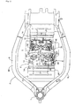
- Fig. 2 is a partially enlarged planar cross-sectional view taken along a line 2-2 in Fig. 1
- Fig. 3 is a side view taken along a line 3-3 in Fig. 2
- Fig. 4 is an enlarged view of a portion in Fig. 3 which is surrounded by an imaginary line.
- a front fork 2 which pivotally supports a front wheel WF is steerablly supported on a head pipe 1 mounted on a front end of a vehicle body frame F of the motorcycle, and a steering handle 3 is mounted on an upper portion of the front fork 2.
- a rear fork 4 which pivotally supports a rear wheel WR is supported in a vertically swingable manner, and the rear fork 4 is suspended on the vehicle body frame F by way of a suspension unit 5.
- a V-type internal combustion engine E for driving the motorcycle for traveling is supported by way of a usual mounting unit, and an output shaft 6 of the internal combustion engine E is interlockingly connected to the rear wheel WR by way of a chain power transmission mechanism 7.
- a main frame 8 of the vehicle body frame F has left and right portions 8L, 8R thereof which face left and right side surfaces of the internal combustion engine E in an opposed manner curved outwardly in the lateral direction.
- the V-type internal combustion engine E is stored in the inside of the main frame 8, and the intake system structure according to the present invention is provided to the V-type internal combustion engine E. Further, a seat S on which a rider sits is arranged above the vehicle body frame F at a rear upper portion of the V-type internal combustion engine E.
- the V-type internal combustion engine E is a four-cylinder OHC-type four-cycle engine, wherein the V-type internal combustion engine E includes a front bank BF which extends upwardly toward a front side of the motorcycle and a rear bank BR which extends upwardly toward a rear side of the motorcycle, and the banks BF, BR respectively include two cylinders which are arranged in parallel in the lateral direction.
- the front and rear banks BF, BR are formed into a V-shape as viewed in a side view of the motorcycle, and a V-shaped space V is defined between the front and rear banks BF, BR.
- crankcase 9 Lower portions of the front and rear banks BF, BR are integrally connected to each other using a crankcase 9, and a crankshaft 10 which is rotatably supported on the crankcase 9 extends in the direction which is orthogonal to the advancing direction of the motorcycle.
- the front bank BF and the rear bank BR respectively include a cylinder block 13 having a pair of cylinders 12, 12 which are arranged in parallel in the lateral direction, a cylinder head 14 which is joined to a deck surface of the cylinder block 13, and a head cover 15 which integrally covers the cylinder head 14 from above.
- Pistons 16 which are respectively fitted in the inside of respective two cylinders 12, 12 of the front and rear banks BF, BR in a slidable manner are connected to the crankshaft 10 by way of connection rods 17.
- combustion chambers 18 which face top surfaces of the pistons 16 in an opposed manner corresponding to the respective cylinders 12 are formed, and front and rear intake ports 19F, 19R and front and rear exhaust ports 20F, 20R which are communicated with the combustion chambers 18 are formed.
- These intake and exhaust ports 19F, 19R, 20F and 20R are respectively opened and closed by intake and exhaust valves 21, 22, and these intake and exhaust valves 21, 22 are opened and closed at predetermined timing due to an operation of a valve operating mechanism not shown in the drawing.
- the V-type internal combustion engine E is configured such that the crankshaft 10 thereof is arranged in the direction (lateral direction) orthogonal to the advancing direction of the motorcycle, and respective cylinder axes LF, LR of the front bank BF and the rear bank BR are arranged to assume a V-shape as viewed in the axial direction of the crankshaft 10.
- a distance D1 between the cylinder axes LF, LF of two cylinders 12, 12 of the front bank BF which are arranged in parallel in the lateral direction is set larger than a distance D2 between the cylinder axes LR, LR of two cylinders 12, 12 of the rear bank BR which are arranged in parallel in the lateral direction.
- the front intake ports 19F which are respectively communicated with two cylinders 12 of the front bank BF extends rearwardly from the front bank BF, and have outer ends thereof opened in the V-shaped space V and communicated with an intake system IN.
- a plurality of rear intake ports 19R which are communicated with two cylinders 12 of the rear bank BR extends frontwardly from the rear bank BR, and have outer ends thereof opened in the V-shaped space V and communicated with the intake system IN.
- the plurality of front exhaust ports 20F which are communicated with two cylinders 12 of the front bank BF extend frontwardly from the front bank BF, and have outer ends thereof opened frontwardly from the front bank BF and communicated with an exhaust system EX.
- the rear exhaust ports 20R which are communicated with two cylinders 12 of the rear bank BR extends rearwardly from the rear bank BR, and has an outer end thereof opened rearwardly from the rear bank BR and communicated with the exhaust system EX.
- the exhaust system EX extends rearwardly from the internal combustion engine E, and a silencer M (see Fig. 1) is connected to a downstream end of the exhaust system EX.
- the intake system IN of the V-type internal combustion engine E includes an air cleaner AC which is arranged on an upper portion of the V-shaped space V of the V-type internal combustion engine E, a pair of respective front and rear throttle bodies 25F, 25R which are respectively connected to a discharge port formed in a lower portion of the air cleaner AC, and front and rear intake ports 19F, 19R which are respectively connected to the throttle bodies 25F, 25R.
- Both of respective pairs of left and right front and rear throttle bodies 25F, 25R are arranged in the inside of the V-shaped space V.
- the left and right front throttle bodies 25F, 25F are arranged close to a rear surface side of the front bank BF and, at the same time, are arranged in parallel in the lateral direction with a distance d1 therebetween.
- left and right rear throttle bodies 25R, 25R are arranged close to the front surface side of the rear bank BR and, at the same time, are arranged in parallel in the lateral direction with a distance d2 which is narrower than the distance d1.
- inner half portions of the left and right rear throttle bodies 25R, 25R which are arranged close to each other and the left and right front throttle bodies 25F, 25F do not overlap each other as viewed in the longitudinal direction. That is, the inner half portions of the left and right rear throttle bodies 25R, 25R which are arranged close to each other are released frontwardly without being obstructed by the left and right front throttle bodies 25F, 25F.
- Upstream sides of front and rear intake passages 26F, 26R which are formed in the inside of the pair of left and right front throttle bodies 25F, 25F and the pair of left and right rear throttle bodies 25R, 25R are respectively communicated with discharge ports formed in the lower portion of the air cleaner AC, and downstream sides of the front and rear intake passages 26F, 26R are respectively communicated with upstream ends of the front and rear intake ports 19F, 19R.
- Butterfly-type front and rear throttle valves 27F, 27R are arranged in the front and rear intake passages 26F, 26R formed in the inside of the front and rear throttle bodies 25F, 25R in a state that the front and rear throttle valves 27F, 27R can be opened and closed between a full-open position and a full-closed position.
- fuel injection valves 24 are respectively mounted, and fuel injection nozzles of the fuel injection valves 24 are respectively directed toward insides of the left and right front intake ports 19F and the left and right rear intake ports 19R.
- both of the pair of left and right front throttle valves 27F, 27F on the front bank BF side are connected with each other using a common front valve shaft 28.
- the pair of left and right rear throttle valves 27R, 27R of the rear bank BR side are separately connected to respective rear valve shafts 29.
- One front valve shaft 28 which is commonly connected to the pair of left and right front throttle valves 27F, 27F extends in the lateral direction between the front throttle bodies 25F, 25F, and both ends of the front valve shaft 28 are rotatably supported on the respective throttle bodies 25F, 25F.
- the rear valve shafts 29, 29 are respectively rotatably supported on the pair of left and right rear throttle bodies 26R, 25R in a laterally coaxial manner.
- the respective front throttle valves 27F, 27F of the left and right front throttle bodies 25F, 25F are commonly driven by one electrically-operated actuator AE, while the respective rear throttle valves 27R, 27R of the left and right rear throttle bodies 25R, 25R are respectively independently driven by two electrically-operated actuators AE, AE.
- one electrically-operated actuator AE which drives both of the left and right front throttle valves 27F, 27F is provided, and the electrically-operated actuator AE is arranged between the front throttle body 25F and one cylinder head 14 mounted on the front bank BF.
- two electrically-operated actuators AE, AE which independently drive the left and right rear throttle valves 27R, 27R are respectively provided, and the electrically-operated actuators AE, AE are respectively arranged between the rear throttle bodies 25R, 25R and the left and right cylinder heads 14, 14 of the rear banks BR, BR.
- a storing space having a relatively large volume can be ensured below the actuators AE and hence, it is possible to store and arrange the auxiliary equipments of the internal combustion engine E in the storing space.
- a drive motor 33 is housed and supported in the inside of the housing 32 which is integrally formed with one (left) front throttle body 25F. Further, to an outer end wall of the one front throttle body 25F, a cover body 35 is fixed with a sealing material 34 sandwiched therebetween. A power transmission chamber 36 is formed inside the cover body 35. In the inside of the power transmission chamber 36, a pinion 37 which is fixed to an output end of the drive motor 33 is arranged.
- a front valve shaft 28 which serves in common for the left and right front throttle valves 27F, 27F faces the inside of the power transmission chamber 36, and a sector gear 38 is engaged with the outer end of the front valve shaft 28 by spline fitting.
- the sector gear 38 is interlockingly connected with a pinion 37 of the drive motor 33 by way of an idle gear 39 which is rotatably supported between the front throttle body 25F and the cover body 35. Due to the driving of the drive motor 33, the front valve shaft 28 is driven with deceleration, and the left and right front throttle valves 27F, 27F which are fixed to the front valve shaft 28 are simultaneously driven to be opened or closed from a full open position to a full closed position.
- a return spring 40 which serves for returning the left and right front throttle valves 27F, 27F to the full closed position and is made of a torsion spring is arranged between an inner end wall of the front throttle body 25F and the sector gear 28.
- a rotational angle sensor 41 is arranged to face an end surface of the front valve shaft 28 in an opposed manner and an opening of the front throttle valves 27F, 27F is detected by the rotational angle sensor 41.
- the drive motor 33 of the electrically-operated actuator AE When a rider of a motorcycle manipulates a manipulation portion of a throttle grip or the like, the drive motor 33 of the electrically-operated actuator AE is rotated in response to a manipulation quantity, and this rotation is transmitted to the front valve shaft 28 by way of the pinion 37, the idle gear 39 and the sector gear 38 and hence, the front valve shaft 28 is rotated with deceleration whereby the left and right front throttle valves 27F, 27F can be simultaneously opened against a closing force of the return spring 40.
- the drive motor 33 of the electrically-operated actuator AE which is mounted on one front throttle body 25F is arranged in front of the front throttle body 25F.
- the left and right front throttle valves 27F, 27F, one (left) rear throttle valve 27R and another (right) rear throttle valve 27R are respectively subjected to drive controls by three electrically-operated actuators AE ... and hence, by selectively performing valve opening controls of the left and right front throttle valves 27F, 27F, one rear throttle valve 27R and another rear throttle valve 27R, it is possible to perform controls of proper intake quantities for respective cylinders in total consisting of the cylinder of the front bank BF, one cylinder of the rear bank BR and another cylinder of the rear bank BR thus enabling proper operation controls of operations of the engine E such as a low-load operation, an intermediate operation, a high-load operation and the like.
- a wind guide opening 43 having a rectangular cross-sectional shape is opened at an intermediate portion of the front bank BF in the left-and-right direction of a portion close to the crankcase 9, that is, between the left and right cylinder blocks 13, 13 which are laterally arranged in parallel.
- a front face of the wind guide opening 43 is formed frontwardly toward a front side of the front bank BF, while a rear face of the wind guide opening 43 is formed toward a V-shaped space V, and a traveling wind which is generated by traveling of the motorcycle is introduced to the V-shaped space V through the wind guide opening 43 thus effectively cooling the front and rear throttle bodies 25F, 25R, the electrically-operated actuators AE ... and the like of the intake system IN arranged in the inside of the V-shaped space V.
- the drive motors 33 of the respective electrically-operated actuators AE are rotated corresponding to the manipulation quantity of the manipulating portion and can perform the drive controls of the front and rear throttle valves 27F, 27R.
- the respective drive motors 33 of the electrically-operated actuators AE ...
- the plurality of electrically-operated actuators AE ... which are arranged in the V-shaped space V between the front and rear banks BF, BR are respectively arranged in the space sandwiched by the cylinder heads 14 of the front and rear banks BF, BR and the front and rear throttle bodies 25F, 25R. Accordingly, it is possible to ensure the housing space for arranging the auxiliary equipment in the inside of the V-shaped space V and, at the same time, the electrically-operated actuators AE ... can be spaced apart from a space in which the hot air is easily filled in the inside of the V-shaped space V and hence, the overheat of the electrically-operated actuator AE can be avoided thus increasing the durability against the heat.
- the electrically-operated actuator AE is arranged in only one of left and right front throttle bodies 25F, 25F which are mounted on the front bank BF, it is possible to easily introduce the traveling wind to the electrically-operated actuator AE on the rear bank BR side from the space on a side where the electrically-operated actuator AE is not arranged whereby the cooling property of two electrically-operated actuators AE, AE arranged in the rear bank BR can be increased. Further, the traveling wind is introduced into the V-shaped space V through the wind guide opening 43 formed in the front bank BF thus effectively cooling the electrically-operated actuators AE ... in the inside of the V-shaped space V.
- Fig. 5 is a view corresponding to Fig. 2 in the above-mentioned first embodiment and parts identical with the parts of the first embodiment are given same symbols.
- left and right front throttle valves 27F, 27F are driven by the respective electrically-operated actuators AE, AE and, at the same time, the left and right rear throttle valves 27R, 27R are driven by the common one electrically-operated actuator AE.
- the left and right front throttle bodies 25F, 25F which are arranged in parallel in the lateral direction are respectively provided with the front valve shafts 128, 128 which are fixed to the front throttle valves 27F, 27F mounted thereon.
- These front valve shafts 128, 128 are arranged coaxially in the lateral direction.
- Electrically-operated actuators AE, AE are respectively mounted on the left and right front throttle bodies 25F, 25F, and the left and right front throttle valves 27F, 27F are individually driven by the electrically-operated actuators AE, AE. Further, on the front surface side of the rear bank BR, the left and right rear throttle bodies 25R, 25R which are laterally arranged in parallel are provided with one common rear valve shaft 129 which is fixed to the rear throttle valves 27R, 27R mounted thereon, and the rear valve shaft 129 extends in the lateral direction.
- the electrically-operated actuator AE is mounted on one (right) of the left and right rear throttle bodies 25R, 25R, and both of the left and right rear throttle valves 27R, 27R are driven by the electrically-operated actuator AE.
- a wind guide opening 43 for a cooling wind is formed in the front bank BF between left and right cylinder blocks 13, 13 and the wind guide opening 43 is opened in a longitudinal surface of the front bank BF between the left and right front throttle bodies 25F, 25F and traveling wind is guided into a V-shaped space V through a space defined between the left and right front throttle bodies 25F, 25F.
- a distance D1 between cylinder axes LF, LF of left and right cylinder blocks 13, 13 of the front bank BF is set larger than a distance D2 between cylinder axes LR, LR of the left and right cylinder blocks 13, 13 of the rear bank BR.
- the cooling property of these actuators AE can be enhanced.
- a vehicle width at a riding position of the rider on which the rider sits on a seat S behind the internal combustion engine E is set smaller than the vehicle width in front of the riding position. Accordingly, the comfortableness of the rider can be enhanced.
- the explanation is made with respect to a case in which the intake system structure according to the present invention is applied to the V-type internal combustion engine of the motorcycle.
- the intake system structure according to the present invention is applicable to other V-type internal combustion engines of other vehicles.
- the present invention can arrange electrically-operated actuators for driving throttle valves in a V-shaped space defined between front and rear banks of a V-type internal combustion engine by avoiding the formation of a region into which hot air is liable to easily filled in the V-shaped space thus preventing the overheat of the actuators whereby the durability of the electrically-operated actuators can be enhanced. Further, in spite of the fact that the electrically-operated actuators are arranged in the V-shaped space, it is possible to ensure a storing space for arranging auxiliary equipment or the like in the V-shaped space.
- the invention is directed to an intake system IN of an internal combustion engine is arranged in a V-shaped space V formed between front and rear banks BF, BR, and the intake system IN includes front and rear throttle bodies 25F, 25R which form front and rear throttle valves 27F, 27R thereon, and electrically-operated actuators AE which drive the throttle valves 27F, 27R.
- the electrically-operated actuators AE are respectively arranged between cylinder heads 14 of the front and rear banks RF, BR and the front and rear throttle bodies 25F, 25R.
Landscapes
- Engineering & Computer Science (AREA)
- Chemical & Material Sciences (AREA)
- Combustion & Propulsion (AREA)
- Mechanical Engineering (AREA)
- General Engineering & Computer Science (AREA)
- Control Of Throttle Valves Provided In The Intake System Or In The Exhaust System (AREA)
Abstract
Description
- The present invention relates to an intake system structure of an internal combustion engine, and more particularly to an intake system structure which includes an electrically-operated actuator for driving a throttle valve in the inside of a throttle body which is provided to an intake system.
- Conventionally, in a V-type internal combustion engine, there has been known an intake system structure of an internal combustion engine in which a throttle valve for controlling a flow rate of intake air which flows in an intake passage in the inside of the throttle body provided to the intake system is driven by an electrically-operated actuator based on a throttle manipulation quantity, and the electrically-operated actuator is arranged in a V-shaped space defined between two banks which are arranged in a V-shape (see patent document
JP-A-2002-256900 - Here, the V-shaped space which is sandwiched between two banks is a space in which various kinds of auxiliary equipments or the like of the internal combustion engine are arranged. Accordingly, in an attempt to arrange the electrically-operated actuator for driving the throttle valve in the space, it is necessary to take a measure which does not impose restriction on the arrangement of the auxiliary equipments. Further, the V-shaped space is sandwiched between two heated banks and hence, the V-shaped space is liable to be easily filled with hot air. Accordingly, it is necessary to take a measure to prevent the electrically-operated actuator, especially, a drive motor of the electrically-operated actuator from being thermally influenced by the hot air thus enhancing the durability thereof. However, the intake system structure described in the
patent document JP-A-2002-256900 - The present invention has been made under such circumstances and it is an object of the present invention to provide a novel intake system structure of a V-type internal combustion engine which can ensure a space for arranging existing auxiliary equipments or the like in a V-shaped space and can enhance the cooling property of an electrically-operated actuator thus enhancing the durability of the electrically-operated actuator.
- To achieve the above-mentioned objects, the invention described in claim 1 is directed to an intake system structure of a V-type internal combustion engine in which the intake system structure includes front and rear banks, cylinder axes of the cylinders formed on the respective banks exhibit a V shape as viewed in the direction of a crankshaft, front and rear intake ports which are formed in the respective front and rear banks are respectively communicably connected with an intake system which is arranged in a V-shaped space defined between the banks, and the intake system includes front and rear throttle bodies which mount front and rear throttle valves thereon and electrically-operated actuators for driving the throttle valves, wherein the electrically-operated actuators are respectively arranged between cylinder heads of the front and rear banks and the front and rear throttle bodies.
- Further, to achieve the above-mentioned object, the invention described in
claim 2 is, in the invention described in claim 1, characterized in that the V-type internal combustion engine is a 4-cylinder engine which mounts two cylinders on the front and rear banks respectively, and in a state that the V-type internal combustion engine is mounted on a vehicle, a crankshaft of the V-type internal combustion engine is arranged orthogonal to the advancing direction of the vehicle, and a plurality of electrically-operated actuators are mounted on the front bank which is positioned on a front side in the advancing direction of the vehicle. - Further, to achieve the above-mentioned object, the invention described in
claim 3 is, in the invention described in claim 1, characterized in that the V-type internal combustion engine is a 4-cylinder engine which mounts two cylinders on the front and rear banks respectively, and in a state that the V-type internal combustion engine is mounted on a vehicle, a crankshaft of the V-type internal combustion engine is arranged orthogonal to the advancing direction of the vehicle, and one electrically-operated actuator is mounted on the front bank which is positioned on a front side in the advancing direction of the vehicle, and two electrically-operated actuators are mounted on the rear bank which is positioned on a rear side in the advancing direction of the vehicle. - Further, to achieve the above-mentioned object, the invention described in
claim 4 is, in the invention described inclaim 2 orclaim 3, characterized in that the V-type internal combustion engine is configured such that a distance between the cylinder axes of two cylinders which are arranged in parallel in the lateral direction of the front bank positioned on a front side in the advancing direction of the vehicle is set larger than a distance between the cylinder axes of two cylinders arranged in parallel in the lateral direction of the rear bank positioned on a rear side in the advancing direction of the vehicle, and a cooling wind guide opening which is communicated with a front portion of the bank and the V-shaped space is formed in an intermediate portion of the front bank in the lateral direction. - According to the inventions described in the respective claims, it is possible to arrange the electrically-operated actuators for driving the throttle valves in the V-shaped space defined between the front and rear banks by avoiding the formation of a region into which hot air is liable to easily filled in the V-sbaped space and hence, it is possible to reduce the influence of the heat on the electrically-operated actuators whereby the durability of the electrically-operated actuators can be enhanced. Further, in spite of the fact that the electrically-operated actuators are arranged in the V-shaped space, it is possible to ensure a space for arranging auxiliary equipment or the like in the V-shaped space.
- Further, according to the invention described in
claim 2, by mounting the plurality of electrically-operated actuators on the front bank which is liable to be easily cooled by a cooling wind, the cooling property of the electrically-operated actuators can be further enhanced. - According to the invention described in
claim 3, by mounting one electrically-operated actuator on the front bank which is positioned on the front side in the advancing direction of the vehicle and by mounting two electrically-operated actuators on the rear bank which is positioned on the rear side in the advancing direction of the vehicle, it is possible to perform not only a control of proper intake air quantities for a plurality of respective cylinders but also, in the front bank on which one electrically-operated actuator is arranged, the introduction of a traveling wind to the electrically-operated actuators mounted on the rear bank from a space which is formed on a side where the actuator is not arranged thus effectively cooling the electrically-operated actuators on the rear bank side. - According to the invention described in
claim 4, the cooling wind which is generated by the traveling of the vehicle can be positively introduced into the V-shaped space through the cooling wind introducing opening formed in the front bank and can be supplied to the rear bank and hence, even when the electrically-operated actuators are mounted on the rear bank, it is possible to effectively cool the actuators thus largely enhancing the cooling property of all electrically-operated actuators which are formed in the V-shaped space. -
- Fig. 1: A whole side view of a motorcycle which is provided with the intake system structure of a V-type internal combustion engine of the present invention.
- Fig. 2: A partial enlarged planer cross-sectional view taken along a line 2-2 in Fig. 1.
- Fig. 3: A side view taken along a line 3-3 in Fig. 2.
- Fig. 4: An enlarged view of a portion surrounded by an imaginary line shown in Fig. 3.
- Fig. 5: A view showing a second embodiment corresponding to Fig. 2.
- Hereinafter, modes for carrying out the present invention are specifically explained in conjunction with embodiments of the present invention shown in attached drawings.
- In this embodiment, a case in which an intake system structure of the present invention is applied to a motorcycle-use V-type internal combustion engine is explained, and in the explanation made hereinafter, a front side of the advancing direction of the motorcycle is set as "front", a rear side of the advancing direction of the motorcycle is set as "rear", a left side of the advancing direction of the motorcycle is set as "left" and a right side of the advancing direction of the motorcycle is set as "right".
- First of all, a first embodiment of the present invention is explained in conjunction with Fig. 1 to Fig. 4. Fig. 1 is a whole side view of a motorcycle which includes an intake system structure of a V-type internal combustion engine according to the present invention, Fig. 2 is a partially enlarged planar cross-sectional view taken along a line 2-2 in Fig. 1, Fig. 3 is a side view taken along a line 3-3 in Fig. 2, and Fig. 4 is an enlarged view of a portion in Fig. 3 which is surrounded by an imaginary line.
- In Fig. 1, a
front fork 2 which pivotally supports a front wheel WF is steerablly supported on a head pipe 1 mounted on a front end of a vehicle body frame F of the motorcycle, and asteering handle 3 is mounted on an upper portion of thefront fork 2. Further, on a rear portion of the vehicle body frame F, arear fork 4 which pivotally supports a rear wheel WR is supported in a vertically swingable manner, and therear fork 4 is suspended on the vehicle body frame F by way of asuspension unit 5. - On an intermediate portion of the vehicle body frame F in the longitudinal direction, a V-type internal combustion engine E for driving the motorcycle for traveling is supported by way of a usual mounting unit, and an
output shaft 6 of the internal combustion engine E is interlockingly connected to the rear wheel WR by way of a chainpower transmission mechanism 7. - As shown in Fig. 2, a
main frame 8 of the vehicle body frame F has left andright portions main frame 8, and the intake system structure according to the present invention is provided to the V-type internal combustion engine E. Further, a seat S on which a rider sits is arranged above the vehicle body frame F at a rear upper portion of the V-type internal combustion engine E. - As shown in Fig. 1 to Fig. 3, the V-type internal combustion engine E is a four-cylinder OHC-type four-cycle engine, wherein the V-type internal combustion engine E includes a front bank BF which extends upwardly toward a front side of the motorcycle and a rear bank BR which extends upwardly toward a rear side of the motorcycle, and the banks BF, BR respectively include two cylinders which are arranged in parallel in the lateral direction. The front and rear banks BF, BR are formed into a V-shape as viewed in a side view of the motorcycle, and a V-shaped space V is defined between the front and rear banks BF, BR. Lower portions of the front and rear banks BF, BR are integrally connected to each other using a
crankcase 9, and acrankshaft 10 which is rotatably supported on thecrankcase 9 extends in the direction which is orthogonal to the advancing direction of the motorcycle. - As shown in Fig. 2 and Fig. 3, the front bank BF and the rear bank BR respectively include a
cylinder block 13 having a pair ofcylinders cylinder head 14 which is joined to a deck surface of thecylinder block 13, and ahead cover 15 which integrally covers thecylinder head 14 from above.Pistons 16 which are respectively fitted in the inside of respective twocylinders crankshaft 10 by way of connection rods 17. In therespective cylinder heads 14 of the front and rear banks BF, BR, combustion chambers 18 which face top surfaces of thepistons 16 in an opposed manner corresponding to therespective cylinders 12 are formed, and front andrear intake ports rear exhaust ports exhaust ports exhaust valves exhaust valves - Here, as shown in Fig. 2 and Fig. 3, the V-type internal combustion engine E is configured such that the
crankshaft 10 thereof is arranged in the direction (lateral direction) orthogonal to the advancing direction of the motorcycle, and respective cylinder axes LF, LR of the front bank BF and the rear bank BR are arranged to assume a V-shape as viewed in the axial direction of thecrankshaft 10. Further, a distance D1 between the cylinder axes LF, LF of twocylinders cylinders - The
front intake ports 19F which are respectively communicated with twocylinders 12 of the front bank BF extends rearwardly from the front bank BF, and have outer ends thereof opened in the V-shaped space V and communicated with an intake system IN. Further, a plurality ofrear intake ports 19R which are communicated with twocylinders 12 of the rear bank BR extends frontwardly from the rear bank BR, and have outer ends thereof opened in the V-shaped space V and communicated with the intake system IN. Further, the plurality offront exhaust ports 20F which are communicated with twocylinders 12 of the front bank BF extend frontwardly from the front bank BF, and have outer ends thereof opened frontwardly from the front bank BF and communicated with an exhaust system EX. Further, therear exhaust ports 20R which are communicated with twocylinders 12 of the rear bank BR extends rearwardly from the rear bank BR, and has an outer end thereof opened rearwardly from the rear bank BR and communicated with the exhaust system EX. The exhaust system EX extends rearwardly from the internal combustion engine E, and a silencer M (see Fig. 1) is connected to a downstream end of the exhaust system EX. - As shown in Fig. 1 and Fig. 3, the intake system IN of the V-type internal combustion engine E includes an air cleaner AC which is arranged on an upper portion of the V-shaped space V of the V-type internal combustion engine E, a pair of respective front and
rear throttle bodies rear intake ports throttle bodies rear throttle bodies front throttle bodies rear throttle bodies rear throttle bodies front throttle bodies rear throttle bodies front throttle bodies - Upstream sides of front and
rear intake passages front throttle bodies rear throttle bodies rear intake passages rear intake ports rear throttle valves rear intake passages rear throttle bodies rear throttle valves - As shown in Fig. 3, on wall surfaces of the respective left and right
front throttle bodies 25F and the respective left and rightrear throttle bodies 25R which are arranged to face each other in an opposed manner,fuel injection valves 24 are respectively mounted, and fuel injection nozzles of thefuel injection valves 24 are respectively directed toward insides of the left and rightfront intake ports 19F and the left and rightrear intake ports 19R. - As shown in Fig. 2, both of the pair of left and right
front throttle valves front valve shaft 28. On the other hand, the pair of left and rightrear throttle valves rear valve shafts 29. - One
front valve shaft 28 which is commonly connected to the pair of left and rightfront throttle valves front throttle bodies front valve shaft 28 are rotatably supported on therespective throttle bodies rear valve shafts rear throttle bodies - The respective
front throttle valves front throttle bodies rear throttle valves rear throttle bodies front throttle body 25F, one electrically-operated actuator AE which drives both of the left and rightfront throttle valves front throttle body 25F and onecylinder head 14 mounted on the front bank BF. Further, to the left and rightrear throttle bodies rear throttle valves rear throttle bodies - Although the above-mentioned three electrically-operated actuators AE ... differ in their relative arrangement with respect to the front and
rear throttle bodies front throttle valves - In Fig. 4, out of the left and right
front throttle bodies housing 32 which is integrally formed with one (left)front throttle body 25F, adrive motor 33 is housed and supported. Further, to an outer end wall of the onefront throttle body 25F, acover body 35 is fixed with a sealingmaterial 34 sandwiched therebetween. Apower transmission chamber 36 is formed inside thecover body 35. In the inside of thepower transmission chamber 36, apinion 37 which is fixed to an output end of thedrive motor 33 is arranged. An outer end of afront valve shaft 28 which serves in common for the left and rightfront throttle valves power transmission chamber 36, and asector gear 38 is engaged with the outer end of thefront valve shaft 28 by spline fitting. Thesector gear 38 is interlockingly connected with apinion 37 of thedrive motor 33 by way of anidle gear 39 which is rotatably supported between thefront throttle body 25F and thecover body 35. Due to the driving of thedrive motor 33, thefront valve shaft 28 is driven with deceleration, and the left and rightfront throttle valves front valve shaft 28 are simultaneously driven to be opened or closed from a full open position to a full closed position. In the inside of the power transmission chamber 26, areturn spring 40 which serves for returning the left and rightfront throttle valves front throttle body 25F and thesector gear 28. Arotational angle sensor 41 is arranged to face an end surface of thefront valve shaft 28 in an opposed manner and an opening of thefront throttle valves rotational angle sensor 41. - When a rider of a motorcycle manipulates a manipulation portion of a throttle grip or the like, the
drive motor 33 of the electrically-operated actuator AE is rotated in response to a manipulation quantity, and this rotation is transmitted to thefront valve shaft 28 by way of thepinion 37, theidle gear 39 and thesector gear 38 and hence, thefront valve shaft 28 is rotated with deceleration whereby the left and rightfront throttle valves return spring 40. Here, thedrive motor 33 of the electrically-operated actuator AE which is mounted on onefront throttle body 25F is arranged in front of thefront throttle body 25F. - As shown in Fig. 2 and Fig. 3, on the left and right
rear throttle bodies rear throttle valves respective throttle valves 27R are respectively independently driven by the respective electrically-operated actuators AE, AE, and therespective drive motors rear throttle bodies - As described above, the left and right
front throttle valves rear throttle valve 27R and another (right)rear throttle valve 27R are respectively subjected to drive controls by three electrically-operated actuators AE ... and hence, by selectively performing valve opening controls of the left and rightfront throttle valves rear throttle valve 27R and anotherrear throttle valve 27R, it is possible to perform controls of proper intake quantities for respective cylinders in total consisting of the cylinder of the front bank BF, one cylinder of the rear bank BR and another cylinder of the rear bank BR thus enabling proper operation controls of operations of the engine E such as a low-load operation, an intermediate operation, a high-load operation and the like. - As shown in Fig. 2 and Fig. 3, at an intermediate portion of the front bank BF in the left-and-right direction of a portion close to the
crankcase 9, that is, between the left and right cylinder blocks 13, 13 which are laterally arranged in parallel, awind guide opening 43 having a rectangular cross-sectional shape is opened. A front face of thewind guide opening 43 is formed frontwardly toward a front side of the front bank BF, while a rear face of thewind guide opening 43 is formed toward a V-shaped space V, and a traveling wind which is generated by traveling of the motorcycle is introduced to the V-shaped space V through the wind guide opening 43 thus effectively cooling the front andrear throttle bodies - Next, the manner of operation of the first embodiment is explained.
- First of all, when the rider manipulates the manipulating portion of the throttle grip or the like, the
drive motors 33 of the respective electrically-operated actuators AE are rotated corresponding to the manipulation quantity of the manipulating portion and can perform the drive controls of the front andrear throttle valves respective drive motors 33 of the electrically-operated actuators AE ... are selectively driven to individually drive the left and rightfront throttle valves rear throttle valve 27R and another (right)rear throttle valve 27R and hence, proper intake quantities of the front cylinder and the rear left and right cylinders can be controlled and, at the same time, even when one or two electrically-operated actuators AE suffer from a breakdown due to a certain cause, it is possible to continue the running of the engine E by another electrically-operated actuators AE. - Here, the plurality of electrically-operated actuators AE ... which are arranged in the V-shaped space V between the front and rear banks BF, BR are respectively arranged in the space sandwiched by the cylinder heads 14 of the front and rear banks BF, BR and the front and
rear throttle bodies front throttle bodies - Next, the second embodiment of the present invention is explained in conjunction with Fig. 5.
- Fig. 5 is a view corresponding to Fig. 2 in the above-mentioned first embodiment and parts identical with the parts of the first embodiment are given same symbols.
- In the second embodiment, left and right
front throttle valves rear throttle valves front throttle bodies front throttle valves front throttle bodies front throttle valves rear throttle bodies rear valve shaft 129 which is fixed to therear throttle valves rear valve shaft 129 extends in the lateral direction. The electrically-operated actuator AE is mounted on one (right) of the left and rightrear throttle bodies rear throttle valves - In the same manner as the first embodiment, a wind guide opening 43 for a cooling wind is formed in the front bank BF between left and right cylinder blocks 13, 13 and the
wind guide opening 43 is opened in a longitudinal surface of the front bank BF between the left and rightfront throttle bodies front throttle bodies - According to the second embodiment, with the provision of the plurality of electrically-operated actuators AE on the front bank BF which can positively introduce the traveling wind, the cooling property of these actuators AE can be enhanced.
- Here, in the first and second embodiments, since the distance D2 between the cylinder axes LR, LR of the left and
right cylinders right cylinders - Although the embodiments of the present invention have been explained heretofore, the present invention is not limited to such embodiments, and various embodiments are possible within a scope of the present invention.
- For example, in the above-mentioned embodiments, the explanation is made with respect to a case in which the intake system structure according to the present invention is applied to the V-type internal combustion engine of the motorcycle. However, it is needless to say that the intake system structure according to the present invention is applicable to other V-type internal combustion engines of other vehicles.
- The present invention can arrange electrically-operated actuators for driving throttle valves in a V-shaped space defined between front and rear banks of a V-type internal combustion engine by avoiding the formation of a region into which hot air is liable to easily filled in the V-shaped space thus preventing the overheat of the actuators whereby the durability of the electrically-operated actuators can be enhanced. Further, in spite of the fact that the electrically-operated actuators are arranged in the V-shaped space, it is possible to ensure a storing space for arranging auxiliary equipment or the like in the V-shaped space.
- The invention is directed to an intake system IN of an internal combustion engine is arranged in a V-shaped space V formed between front and rear banks BF, BR, and the intake system IN includes front and
rear throttle bodies rear throttle valves throttle valves cylinder heads 14 of the front and rear banks RF, BR and the front andrear throttle bodies
Claims (4)
- An intake system structure of a V-type internal combustion engine in which the intake system structure includes front and rear banks (BF, BR), cylinder axes (LF, LR) of the cylinders (12, 12) formed on the respective banks (BF, BR) exhibit a V shape as viewed in the direction of a crankshaft (10), front and rear intake ports (19F, 19R) which are formed in the respective front and rear banks (BF, BR) are respectively communicably connected with an intake system (IN) which is arranged in a V-shaped space (V) defined between the banks (BF, BR), and the intake system (IN) includes front and rear throttle bodies (25F, 25R) which mount front and rear throttle valves (27F, 27R) thereon and electrically-operated actuators (AE) for driving the throttle valves (27F, 27R), wherein
the electrically-operated actuators (AE) are respectively arranged between cylinder heads (14) of the front and rear banks (BF, BR) and the front and rear throttle bodies (25F, 25R). - An intake system structure of a V-type internal combustion engine according to claim 1, wherein the V-type internal combustion engine (E) is a 4-cylinder engine which mounts two cylinders on the front and rear banks (BF, BR) respectively, and in a state that the V-type internal combustion engine (E) is mounted on a vehicle, a crankshaft (10) of the V-type internal combustion engine (E) is arranged orthogonal to the advancing direction of the vehicle, and a plurality of electrically-operated actuators (AE) are mounted on the front bank (BF) which is positioned on a front side in the advancing direction of the vehicle.
- An intake system structure of a V-type internal combustion engine according to claim 1, wherein the V-type internal combustion engine (E) is a 4-cylinder engine which mounts two cylinders on the front and rear banks (BF, BR) respectively, and in a state that the V-type internal combustion engine (E) is mounted on a vehicle, a crankshaft (10) of the V-type internal combustion engine (E) is arranged orthogonal to the advancing direction of the vehicle, and one electrically-operated actuator (AE) is mounted on the front bank (BF) which is positioned on a front side in the advancing direction of the vehicle, and two electrically-operated actuators (AE) are mounted on the rear bank (BR) which is positioned on a rear side in the advancing direction of the vehicle.
- An intake system structure of a V-type internal combustion engine according to claim 2 or 3, wherein the V-type internal combustion engine (E) is configured such that a distance (D1) between the cylinder axes (LF) of two cylinders (12) which are arranged in parallel in the lateral direction of the front bank (BF) positioned on a front side in the advancing direction of the vehicle is set larger than a distance (D2) between the cylinder axes (LR) of two cylinders (12) arranged in parallel in the lateral direction of the rear bank (BR) positioned on a rear side in the advancing direction of the vehicle, and a cooling wind guide opening (43) which is communicated with a front portion of the bank (BF) and the V-shaped space (A) is formed in an intermediate portion of the front bank (BF) in the lateral direction.
Applications Claiming Priority (1)
| Application Number | Priority Date | Filing Date | Title |
|---|---|---|---|
| JP2006213297A JP4732272B2 (en) | 2006-08-04 | 2006-08-04 | Intake system structure of a V-type internal combustion engine for motorcycles |
Publications (2)
| Publication Number | Publication Date |
|---|---|
| EP1887212A1 true EP1887212A1 (en) | 2008-02-13 |
| EP1887212B1 EP1887212B1 (en) | 2010-11-03 |
Family
ID=38474056
Family Applications (1)
| Application Number | Title | Priority Date | Filing Date |
|---|---|---|---|
| EP07012102A Not-in-force EP1887212B1 (en) | 2006-08-04 | 2007-06-20 | Intake system structure of V-type internal combustion engine |
Country Status (5)
| Country | Link |
|---|---|
| US (1) | US7533653B2 (en) |
| EP (1) | EP1887212B1 (en) |
| JP (1) | JP4732272B2 (en) |
| DE (1) | DE602007010214D1 (en) |
| ES (1) | ES2353911T3 (en) |
Cited By (3)
| Publication number | Priority date | Publication date | Assignee | Title |
|---|---|---|---|---|
| EP2031197A1 (en) * | 2007-08-31 | 2009-03-04 | Honda Motor Co., Ltd | V- type engine for vehicle |
| EP2141345A1 (en) * | 2008-05-28 | 2010-01-06 | Honda Motor Co., Ltd. | General-purpose V-type engine |
| EP2048351A3 (en) * | 2007-10-10 | 2014-01-22 | Yamaha Hatsudoki Kabushiki Kaisha | Engine unit and vehcile including the same |
Families Citing this family (9)
| Publication number | Priority date | Publication date | Assignee | Title |
|---|---|---|---|---|
| WO2009017189A1 (en) * | 2007-07-31 | 2009-02-05 | Mikuni Corporation | Multiple throttle device |
| JP5086858B2 (en) * | 2008-03-26 | 2012-11-28 | 本田技研工業株式会社 | Internal combustion engine |
| JP5215092B2 (en) * | 2008-09-08 | 2013-06-19 | 川崎重工業株式会社 | Engine and vehicle equipped with this |
| JP5841733B2 (en) * | 2011-03-28 | 2016-01-13 | 本田技研工業株式会社 | Cooling structure for drive motor unit of saddle riding type vehicle |
| JP5719657B2 (en) * | 2011-03-29 | 2015-05-20 | 本田技研工業株式会社 | Saddle riding vehicle |
| RU2719265C2 (en) * | 2012-06-29 | 2020-04-17 | Бомбардье Рекриэйшенел Продактс Инк. | Snowmobile |
| JP6168947B2 (en) * | 2013-09-25 | 2017-07-26 | 本田技研工業株式会社 | Engine with electric throttle valve |
| US20180030936A1 (en) * | 2016-08-01 | 2018-02-01 | G.W. Lisk Company, Inc. | Exhaust gas recirculation valve having crowned spline |
| JP6763921B2 (en) * | 2018-09-07 | 2020-09-30 | 本田技研工業株式会社 | engine |
Citations (5)
| Publication number | Priority date | Publication date | Assignee | Title |
|---|---|---|---|---|
| JP2002256900A (en) | 2001-03-05 | 2002-09-11 | Yamaha Motor Co Ltd | V-type engine throttle control device |
| EP1464811A2 (en) * | 2003-04-04 | 2004-10-06 | HONDA MOTOR CO., Ltd. | Throttle valve opening control device and layout structure thereof |
| EP1548252A1 (en) | 2002-09-11 | 2005-06-29 | Mikuni Corporation | Multiple throttle device |
| EP1555409A1 (en) * | 2002-10-11 | 2005-07-20 | Mikuni Corporation | Multiple throttle device |
| EP1630382A1 (en) * | 2004-08-24 | 2006-03-01 | Honda Motor Co., Ltd. | Intake system of V-type engine for vehicle |
Family Cites Families (6)
| Publication number | Priority date | Publication date | Assignee | Title |
|---|---|---|---|---|
| JPS5960054A (en) * | 1982-09-29 | 1984-04-05 | Honda Motor Co Ltd | Cooling fin for engine |
| JPS62107240A (en) * | 1985-11-02 | 1987-05-18 | Honda Motor Co Ltd | Motorcycle engine |
| JPH0825504B2 (en) * | 1987-02-06 | 1996-03-13 | ヤマハ発動機株式会社 | Vehicle exhaust control device |
| JP2917043B2 (en) * | 1990-05-09 | 1999-07-12 | マツダ株式会社 | Engine intake system |
| JP4463488B2 (en) * | 2003-03-27 | 2010-05-19 | 本田技研工業株式会社 | Throttle body |
| JP4318522B2 (en) * | 2003-10-06 | 2009-08-26 | 本田技研工業株式会社 | Multi-cylinder internal combustion engine |
-
2006
- 2006-08-04 JP JP2006213297A patent/JP4732272B2/en not_active Expired - Fee Related
-
2007
- 2007-06-20 EP EP07012102A patent/EP1887212B1/en not_active Not-in-force
- 2007-06-20 ES ES07012102T patent/ES2353911T3/en active Active
- 2007-06-20 DE DE602007010214T patent/DE602007010214D1/en active Active
- 2007-07-17 US US11/879,305 patent/US7533653B2/en active Active
Patent Citations (5)
| Publication number | Priority date | Publication date | Assignee | Title |
|---|---|---|---|---|
| JP2002256900A (en) | 2001-03-05 | 2002-09-11 | Yamaha Motor Co Ltd | V-type engine throttle control device |
| EP1548252A1 (en) | 2002-09-11 | 2005-06-29 | Mikuni Corporation | Multiple throttle device |
| EP1555409A1 (en) * | 2002-10-11 | 2005-07-20 | Mikuni Corporation | Multiple throttle device |
| EP1464811A2 (en) * | 2003-04-04 | 2004-10-06 | HONDA MOTOR CO., Ltd. | Throttle valve opening control device and layout structure thereof |
| EP1630382A1 (en) * | 2004-08-24 | 2006-03-01 | Honda Motor Co., Ltd. | Intake system of V-type engine for vehicle |
Cited By (3)
| Publication number | Priority date | Publication date | Assignee | Title |
|---|---|---|---|---|
| EP2031197A1 (en) * | 2007-08-31 | 2009-03-04 | Honda Motor Co., Ltd | V- type engine for vehicle |
| EP2048351A3 (en) * | 2007-10-10 | 2014-01-22 | Yamaha Hatsudoki Kabushiki Kaisha | Engine unit and vehcile including the same |
| EP2141345A1 (en) * | 2008-05-28 | 2010-01-06 | Honda Motor Co., Ltd. | General-purpose V-type engine |
Also Published As
| Publication number | Publication date |
|---|---|
| US7533653B2 (en) | 2009-05-19 |
| EP1887212B1 (en) | 2010-11-03 |
| JP2008038734A (en) | 2008-02-21 |
| US20080029055A1 (en) | 2008-02-07 |
| ES2353911T3 (en) | 2011-03-08 |
| JP4732272B2 (en) | 2011-07-27 |
| DE602007010214D1 (en) | 2010-12-16 |
Similar Documents
| Publication | Publication Date | Title |
|---|---|---|
| EP1887212B1 (en) | Intake system structure of V-type internal combustion engine | |
| EP3225809B1 (en) | Internal combustion engine with supercharger for saddle-ride type vehicle | |
| EP1908944A1 (en) | Electronic throttle control device in V-type internal combustion engine for vehicle | |
| JP2006063855A (en) | Fuel supply device for V-type engine for vehicle | |
| JP4442847B2 (en) | Intake pipe length variable device for outboard engine | |
| JP2004162676A (en) | Engine intake device | |
| JP5215092B2 (en) | Engine and vehicle equipped with this | |
| US7690356B2 (en) | Internal combustion engine | |
| JP2009197816A (en) | Engine | |
| JP2009085113A (en) | Engine intake air amount control device | |
| JP5355673B2 (en) | engine | |
| JP4673876B2 (en) | Intake air amount control device for V-type multi-cylinder engine | |
| JP3606822B2 (en) | V-type engine intake / exhaust structure | |
| US7441528B2 (en) | Outboard motor | |
| JP2006266092A (en) | Arrangement structure of idle air control device for internal combustion engine | |
| JP4916529B2 (en) | engine | |
| JP5143275B2 (en) | engine | |
| JP4916562B2 (en) | Throttle control device for motorcycle engine | |
| JP2012246876A (en) | Intake structure of motorcycle | |
| JP4735402B2 (en) | Outboard motor intake system | |
| JP2009197814A (en) | Engine | |
| JP4916530B2 (en) | engine | |
| JP5672151B2 (en) | Intake structure of motorcycle | |
| JP4916527B2 (en) | Motorcycle engine | |
| JP5672152B2 (en) | Intake structure of motorcycle |
Legal Events
| Date | Code | Title | Description |
|---|---|---|---|
| PUAI | Public reference made under article 153(3) epc to a published international application that has entered the european phase |
Free format text: ORIGINAL CODE: 0009012 |
|
| 17P | Request for examination filed |
Effective date: 20070620 |
|
| AK | Designated contracting states |
Kind code of ref document: A1 Designated state(s): AT BE BG CH CY CZ DE DK EE ES FI FR GB GR HU IE IS IT LI LT LU LV MC MT NL PL PT RO SE SI SK TR |
|
| AX | Request for extension of the european patent |
Extension state: AL BA HR MK YU |
|
| AKX | Designation fees paid |
Designated state(s): DE ES GB IT |
|
| 17Q | First examination report despatched |
Effective date: 20090211 |
|
| GRAP | Despatch of communication of intention to grant a patent |
Free format text: ORIGINAL CODE: EPIDOSNIGR1 |
|
| GRAS | Grant fee paid |
Free format text: ORIGINAL CODE: EPIDOSNIGR3 |
|
| GRAA | (expected) grant |
Free format text: ORIGINAL CODE: 0009210 |
|
| RAP1 | Party data changed (applicant data changed or rights of an application transferred) |
Owner name: HONDA MOTOR CO., LTD. |
|
| AK | Designated contracting states |
Kind code of ref document: B1 Designated state(s): DE ES GB IT |
|
| REG | Reference to a national code |
Ref country code: GB Ref legal event code: FG4D |
|
| REF | Corresponds to: |
Ref document number: 602007010214 Country of ref document: DE Date of ref document: 20101216 Kind code of ref document: P |
|
| REG | Reference to a national code |
Ref country code: ES Ref legal event code: FG2A Effective date: 20110224 |
|
| PLBE | No opposition filed within time limit |
Free format text: ORIGINAL CODE: 0009261 |
|
| STAA | Information on the status of an ep patent application or granted ep patent |
Free format text: STATUS: NO OPPOSITION FILED WITHIN TIME LIMIT |
|
| 26N | No opposition filed |
Effective date: 20110804 |
|
| REG | Reference to a national code |
Ref country code: DE Ref legal event code: R097 Ref document number: 602007010214 Country of ref document: DE Effective date: 20110804 |
|
| REG | Reference to a national code |
Ref country code: GB Ref legal event code: 746 Effective date: 20140128 |
|
| REG | Reference to a national code |
Ref country code: DE Ref legal event code: R084 Ref document number: 602007010214 Country of ref document: DE Effective date: 20140204 |
|
| PGFP | Annual fee paid to national office [announced via postgrant information from national office to epo] |
Ref country code: GB Payment date: 20160615 Year of fee payment: 10 |
|
| GBPC | Gb: european patent ceased through non-payment of renewal fee |
Effective date: 20170620 |
|
| PG25 | Lapsed in a contracting state [announced via postgrant information from national office to epo] |
Ref country code: GB Free format text: LAPSE BECAUSE OF NON-PAYMENT OF DUE FEES Effective date: 20170620 |
|
| REG | Reference to a national code |
Ref country code: ES Ref legal event code: FD2A Effective date: 20181114 |
|
| PG25 | Lapsed in a contracting state [announced via postgrant information from national office to epo] |
Ref country code: ES Free format text: LAPSE BECAUSE OF NON-PAYMENT OF DUE FEES Effective date: 20170621 |
|
| PGFP | Annual fee paid to national office [announced via postgrant information from national office to epo] |
Ref country code: ES Payment date: 20190503 Year of fee payment: 17 |
|
| PGFP | Annual fee paid to national office [announced via postgrant information from national office to epo] |
Ref country code: DE Payment date: 20210525 Year of fee payment: 15 |
|
| PG25 | Lapsed in a contracting state [announced via postgrant information from national office to epo] |
Ref country code: IT Free format text: LAPSE BECAUSE OF NON-PAYMENT OF DUE FEES Effective date: 20200620 |
|
| REG | Reference to a national code |
Ref country code: DE Ref legal event code: R119 Ref document number: 602007010214 Country of ref document: DE |
|
| PG25 | Lapsed in a contracting state [announced via postgrant information from national office to epo] |
Ref country code: DE Free format text: LAPSE BECAUSE OF NON-PAYMENT OF DUE FEES Effective date: 20230103 |