EP1887097A2 - Method for concurrent thermal spray and cooling hole cleaning - Google Patents
Method for concurrent thermal spray and cooling hole cleaning Download PDFInfo
- Publication number
- EP1887097A2 EP1887097A2 EP07113362A EP07113362A EP1887097A2 EP 1887097 A2 EP1887097 A2 EP 1887097A2 EP 07113362 A EP07113362 A EP 07113362A EP 07113362 A EP07113362 A EP 07113362A EP 1887097 A2 EP1887097 A2 EP 1887097A2
- Authority
- EP
- European Patent Office
- Prior art keywords
- thermal spraying
- particles
- article
- tbc
- cooling
- Prior art date
- Legal status (The legal status is an assumption and is not a legal conclusion. Google has not performed a legal analysis and makes no representation as to the accuracy of the status listed.)
- Granted
Links
Images



Classifications
-
- C—CHEMISTRY; METALLURGY
- C23—COATING METALLIC MATERIAL; COATING MATERIAL WITH METALLIC MATERIAL; CHEMICAL SURFACE TREATMENT; DIFFUSION TREATMENT OF METALLIC MATERIAL; COATING BY VACUUM EVAPORATION, BY SPUTTERING, BY ION IMPLANTATION OR BY CHEMICAL VAPOUR DEPOSITION, IN GENERAL; INHIBITING CORROSION OF METALLIC MATERIAL OR INCRUSTATION IN GENERAL
- C23C—COATING METALLIC MATERIAL; COATING MATERIAL WITH METALLIC MATERIAL; SURFACE TREATMENT OF METALLIC MATERIAL BY DIFFUSION INTO THE SURFACE, BY CHEMICAL CONVERSION OR SUBSTITUTION; COATING BY VACUUM EVAPORATION, BY SPUTTERING, BY ION IMPLANTATION OR BY CHEMICAL VAPOUR DEPOSITION, IN GENERAL
- C23C4/00—Coating by spraying the coating material in the molten state, e.g. by flame, plasma or electric discharge
- C23C4/04—Coating by spraying the coating material in the molten state, e.g. by flame, plasma or electric discharge characterised by the coating material
- C23C4/06—Metallic material
- C23C4/073—Metallic material containing MCrAl or MCrAlY alloys, where M is nickel, cobalt or iron, with or without non-metal elements
-
- C—CHEMISTRY; METALLURGY
- C23—COATING METALLIC MATERIAL; COATING MATERIAL WITH METALLIC MATERIAL; CHEMICAL SURFACE TREATMENT; DIFFUSION TREATMENT OF METALLIC MATERIAL; COATING BY VACUUM EVAPORATION, BY SPUTTERING, BY ION IMPLANTATION OR BY CHEMICAL VAPOUR DEPOSITION, IN GENERAL; INHIBITING CORROSION OF METALLIC MATERIAL OR INCRUSTATION IN GENERAL
- C23C—COATING METALLIC MATERIAL; COATING MATERIAL WITH METALLIC MATERIAL; SURFACE TREATMENT OF METALLIC MATERIAL BY DIFFUSION INTO THE SURFACE, BY CHEMICAL CONVERSION OR SUBSTITUTION; COATING BY VACUUM EVAPORATION, BY SPUTTERING, BY ION IMPLANTATION OR BY CHEMICAL VAPOUR DEPOSITION, IN GENERAL
- C23C4/00—Coating by spraying the coating material in the molten state, e.g. by flame, plasma or electric discharge
- C23C4/01—Selective coating, e.g. pattern coating, without pre-treatment of the material to be coated
-
- C—CHEMISTRY; METALLURGY
- C23—COATING METALLIC MATERIAL; COATING MATERIAL WITH METALLIC MATERIAL; CHEMICAL SURFACE TREATMENT; DIFFUSION TREATMENT OF METALLIC MATERIAL; COATING BY VACUUM EVAPORATION, BY SPUTTERING, BY ION IMPLANTATION OR BY CHEMICAL VAPOUR DEPOSITION, IN GENERAL; INHIBITING CORROSION OF METALLIC MATERIAL OR INCRUSTATION IN GENERAL
- C23C—COATING METALLIC MATERIAL; COATING MATERIAL WITH METALLIC MATERIAL; SURFACE TREATMENT OF METALLIC MATERIAL BY DIFFUSION INTO THE SURFACE, BY CHEMICAL CONVERSION OR SUBSTITUTION; COATING BY VACUUM EVAPORATION, BY SPUTTERING, BY ION IMPLANTATION OR BY CHEMICAL VAPOUR DEPOSITION, IN GENERAL
- C23C4/00—Coating by spraying the coating material in the molten state, e.g. by flame, plasma or electric discharge
- C23C4/04—Coating by spraying the coating material in the molten state, e.g. by flame, plasma or electric discharge characterised by the coating material
- C23C4/10—Oxides, borides, carbides, nitrides or silicides; Mixtures thereof
- C23C4/11—Oxides
-
- B—PERFORMING OPERATIONS; TRANSPORTING
- B23—MACHINE TOOLS; METAL-WORKING NOT OTHERWISE PROVIDED FOR
- B23P—METAL-WORKING NOT OTHERWISE PROVIDED FOR; COMBINED OPERATIONS; UNIVERSAL MACHINE TOOLS
- B23P2700/00—Indexing scheme relating to the articles being treated, e.g. manufactured, repaired, assembled, connected or other operations covered in the subgroups
- B23P2700/06—Cooling passages of turbine components, e.g. unblocking or preventing blocking of cooling passages of turbine components
-
- Y—GENERAL TAGGING OF NEW TECHNOLOGICAL DEVELOPMENTS; GENERAL TAGGING OF CROSS-SECTIONAL TECHNOLOGIES SPANNING OVER SEVERAL SECTIONS OF THE IPC; TECHNICAL SUBJECTS COVERED BY FORMER USPC CROSS-REFERENCE ART COLLECTIONS [XRACs] AND DIGESTS
- Y02—TECHNOLOGIES OR APPLICATIONS FOR MITIGATION OR ADAPTATION AGAINST CLIMATE CHANGE
- Y02T—CLIMATE CHANGE MITIGATION TECHNOLOGIES RELATED TO TRANSPORTATION
- Y02T50/00—Aeronautics or air transport
- Y02T50/60—Efficient propulsion technologies, e.g. for aircraft
Definitions
- the present invention is directed to methods of applying a thermal spray coating to an article having one or more cooling holes and more particularly to methods of thermal spraying an article having one or more cooling holes and cleaning the cooling holes of the article to remove obstructions resulting from overspray or other debris of thermal spraying.
- gas turbine engines such as aircraft engines for example
- air is drawn into the front of the engine, compressed by a shaft-mounted rotary-type compressor, and mixed with fuel.
- the mixture is burned, and the hot exhaust gases are passed through a turbine mounted on the same shaft as the compressor.
- the flow of gas turns the turbine, which turns the shaft and drives the compressor and fan.
- the hot exhaust gases flow through the engine nozzle at the back of the engine, generating thrust to propel the aircraft forward.
- the temperatures of combustion gases may exceed 1650 °C (3000 °F), considerably higher than the melting temperatures of the metal parts of the engine which are in contact with these gases.
- Operation of these engines at gas temperatures that are above the metal part melting temperatures is a well established art, and depends in part on supplying a cooling air to the outer surfaces of the metal parts through various methods.
- the metal parts of these engines that are particularly subject to high temperatures, and thus require particular attention with respect to cooling, are the metal parts forming combustors and parts located aft of the combustor.
- the metal temperatures can be maintained below melting levels by using thermal barrier coatings (TBCs), often in combination with various cooling hole designs incorporated into some engine components.
- TBCs thermal barrier coatings
- the TBC is typically applied to the component by a thermal spray process.
- the thermal spray process often results in overspray that partially or completely blocks the component's cooling holes.
- the percent blockage typically increases substantially as the thickness of the TBC grows.
- present thermal spray and cleaning processes involve a multi-step, highly labor intensive process of applying a partial layer of TBC coating, allowing the component and the TBC to sufficiently cool to a temperature at which the component can easily be handled, removing the component from an application fixture on which the thermal spraying takes place, and removing any masking, which is then followed by separately removing the well-cooled, solidified coating from the cooling holes using a water jet or other cleaning methods.
- a water jet or other cleaning methods To prevent the cooling holes from becoming obstructed beyond a level from which they can be satisfactorily cleaned, only a fraction of the desired TBC thickness is applied prior to cleaning. As a result, the entire process must typically be repeated several times until the desired TBC thickness is reached. This complex process results in low productivity, high cycle time, and increases costs by a factor of five to ten times that of applying the same TBC to a similar non-holed part.
- What is needed is a method for applying a TBC or other coating by a thermal spray process to an article having cooling holes and cleaning those holes concurrent with the thermal spray process to reduce time and monetary costs associated with current incremental, multi-stage coating and cleaning processes.
- a method for applying a thermal barrier coating to an article having cooling holes and concurrently cleaning obstructions, such as TBC overspray or other debris, from those holes comprises providing an article having a first surface and a second surface, the article having one or more cooling holes extending from an opening in the first surface to an opening in the second surface, thermal spraying a layer of material overlying the first surface of the article, wherein thermal spray debris creates an obstruction that at least partially obstructs at least one cooling hole, and concurrently projecting a plurality of particles toward the second surface of the article, at least some of the particles passing through the cooling hole at the second surface opening and removing at least a portion of the obstruction from the cooling hole.
- One advantage of exemplary embodiments of the invention is that time and cost savings may be achieved by reducing or eliminating masking and other time consuming steps associated with separate thermal spray and cleaning processes.
- Another advantage is that concurrent spray and cleaning processes may reduce the number of stations needed, in that an article can be sprayed and cleaned at a single location.
- thermal barrier coating may be applied to its full desired thickness in a single stage without interruption.
- Yet another advantage of the invention is that concurrent cleaning of cooling holes with thermal spraying permits cleaning overspray from the holes while the applied barrier coating constituents are still warm and pliable, increasing the effectiveness of debris removal over comparable cleaning techniques used after the TBC and the component to which the TBC was applied have substantially cooled and hardened.
- Still another advantage is that component quality may be improved by minimizing wall reduction in the cooling hole.
- an article 10 having cooling holes 12, such as a combustor liner or other component of a gas turbine engine is provided to which a TBC or other coating may be applied by thermal spray.
- a thermal spray device 20 is positioned to apply a TBC 22 to the inner surface of the combustor liner 10 (see Figure 2).
- An abrasive non-metallic particle blaster (i.e. grit blaster) 30 is positioned to direct grit or other particles toward the outer surface of the combustor liner 10 and into the cooling holes 12.
- a rotatable table 15 may provide relative movement between the thermal spray device 20, the grit blaster 30, and the combustor liner 10.
- the cooling holes 12 extend from an opening 21 in a first surface 11 of the combustor liner 10 to which a TBC 22 is applied to a second opening 23 in a second surface 13 of the combustor liner 10.
- the TBC 22 comprises one or more layers of metal and/or ceramic coating material applied to the surface of metal parts to impede the transfer of heat from hot combustion gases to the metal parts, thus insulating the component from the hot combustion gas.
- the presence of the TBC 22 on the surface permits the combustion gas to be hotter than would otherwise be possible with the particular material and fabrication process of the component.
- Any suitable composition of TBC 22 desired may be applied.
- one suitable TBC 22 comprises a bond layer of MCrAlY, wherein M is preferably Ni, Co, or a combination thereof, followed by a layer of yttria stabilized zirconia (YSZ).
- Combustor liners typically have an annular geometry, and as a result, the first surface 11 to which the TBC 22 is applied is usually the inner surface of the combustor liner 10.
- the second, outer, surface 13 is exposed to bypass cooling gases during operation and may be left untreated for more efficient heat transfer.
- the thermal spray device 20, such as an air plasma spray gun is positioned to apply the TBC 22 to the inner surface 11 of the combustor liner 10.
- the spray device 20 may be moved with respect to the combustor liner 10 or vice versa, or some combination of the two may be employed.
- the combustor liner 10 is positioned on the rotable table 15.
- the table 15 may be rotated at any speed, typically about 50 to 75 rotations per minute, while the thermal spray device 20 and grit blaster 30 are stationary. The relative motion may result in depositing a coating approximately one micron thick on the first surface 11 of the combustor liner 10 each time a particular point passes the spray device 20.
- the TBC 22 may be applied to any desired thickness, although a thickness of about 127 microns to about 254 microns (about 5 mils to about 10 mils) for MCrAIY and a thickness of about 254 microns to about 508 microns (about 10 mils to about 20 mils) for YSZ is typical.
- thermal spray debris such as overspray
- These obstructions 32 may partially or completely block the cooling holes 12, thus decreasing or eliminating the cooling holes' ability to serve their intended purpose of cooling unless at least some of those obstructions 32 are removed.
- a grit blaster 30 or other particle emitting device is provided for concurrent cleaning of the cooling holes 12 during the thermal spray process.
- the grit blaster 30 is configured to project small particles 34 toward the second surface 13 of the combustor liner 10.
- the second surface 13 toward which the particles 34 are projected may be any surface of the combustor liner 10 or other component in which the second cooling hole opening 23 is provided and which surface is other than the first surface 11.
- the second surface 13 is typically, but not necessarily, a surface opposite the first surface 11.
- the particles 34 strike the second surface 13 of the combustor liner 10
- a portion of those particles pass into and through the cooling hole(s) 12 at the opening(s) 23 in the second surface 13, some or all of which cooling holes 12 are at least partially obstructed by TBC constituents or other debris that form the obstructions 32 resulting from the thermal spray process.
- the particles 34 are projected from one or more outlet nozzles of the grit blaster 30 aimed at the second surface 13 of the combustor liner 10.
- the grit blaster 30 imparts sufficient velocity to the particles 34 such that when the particles 34 strike the still warm and soft TBC constituents in the cooling hole 12, both the particles 34 and at least some of obstructions 32 are knocked from the cooling hole 12 via the first opening 21 in the first surface 11.
- the grit blaster 30 is positioned for concurrent operation with the thermal spray device 20.
- concurrent is meant that the particles 34 are projected from the grit blaster 30 against the second surface 13 and through the cooling holes 12 simultaneously or shortly after the TBC 22 is applied to the first surface 11 with the spray device 20, such that the TBC constituents have not cooled and solidified, but are sufficiently warm and soft enough to be knocked out of the cooling holes 12 by the particles 34 from the grit blaster 30.
- TBC constituents are typically still sufficiently warm and soft when the concurrent projecting of particles 34 toward the second surface 13 occurs within about 1 second of applying the TBC 22, although concurrent spraying within about 0.1 seconds of applying the thermal barrier coating is preferred, and may occur within about 0.01 seconds to simultaneously with applying the TBC 22.
- the thermal spray device 20 may be positioned at any angle with respect to the first surface 11 of the combustor liner from about 20 degrees to about 230 degrees. More typically, the spray device 20 is angled at about 30 to about 55 degrees, and more typically at about 45 degrees. It will be appreciated that the cooling hole 12 may be angled as it passes from the first surface 11 to the second surface 13 through the combustor liner 10 or other engine component, thereby increasing the length of the hole through the component and providing a greater internal surface area for heat transfer.
- the spray device 20 is preferably angled to minimize the depth into the cooling hole 12 that overspray travels and the number of obstructions 32 which collect therein. This may be achieved by angling the spray device 20 against the angle of the cooling hole 12 at the first opening 21 as shown in Figure 2.
- the grit blaster 30 may have one or more outlet nozzles and may be configured to produce a converging or diverging stream of particles 34.
- the grit blaster 30 may be positioned at any angle with respect to the second surface 13, but is typically angled with the cooling hole 12, and in some circumstances may be aligned substantially parallel with the cooling hole 12. This may increase the depth to which the particles 34 from the grit blaster 30 travel prior to making contact with the internal walls of the cooling hole 12 or the TBC constituents forming obstructions 32 therein, thereby increasing the momentum with which those particles 34 strike those obstructions 32.
- the particles 34 from the grit blaster 30 may be of any suitable material including alumina, sand, glass beads, or any other abrasive non-metallic material, by way of example only, and may be entrained in any suitable fluid, gaseous or liquid. Any desired mesh size grit may be selected, typically in the range of about 60 mesh grit to about 400 mesh grit. Likewise the pressure at which the grit blaster 30 is operated may be varied depending on the size of grit selected, but generally ranges from about 30 psi to about 90 psi.
- Grit size of the particles from the grit blaster 30 and the angle of the thermal spray device 20 during application of the TBC 22 may impact the overall efficacy of the concurrent thermal spraying and cooling hole cleaning process.
- the comparative effects of modifying these features can be calculated by measuring the difference in air flow through the cooling holes of an uncoated component and air flow through cooling holes of a component that has been coated by thermal spraying and its cooling holes concurrently cleaned as described above.
- FIG 3 illustrates results in chart form of sample materials having angled cooling holes to which a TBC was applied with concurrent grit blasting to clean the cooling holes in accordance with exemplary embodiments of the invention.
- a NiCrAlY coating was applied to US 188 samples by air plasma spraying at two different angles and to four levels of coating thickness. The angles of thermal spraying were (1) 90 degrees with respect to the first surface 11 and (2) 45 degrees with respect to the first surface 11, against the angle of the cooling hole 12 in the manner illustrated in Figure 2.
- Alumina of three different grit sizes (120 mesh, 220 mesh and 320 mesh) entrained in air was used as blasting media for concurrent cooling hole cleaning at 60 psi during the thermal spray application.
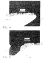
- Figures 4 and 5 are optical micrographs of the sample component in which the NiCrAlY TBC 22 was applied by air plasma spraying at 45 degrees with concurrent grit-blasting using 220 grit alumina at 60 psi. The optical micrographs further demonstrate that the first surface 11 of the sample was successfully coated while the cooling hole 12 in the coated sample is substantially free of any obstructions 32.
- Figure 6 is an optical micrograph of the microstructure of the first surface 11 of the sample and the overlying NiCrAlY TBC 22 illustrating that the microstructure of the first surface 11 and the TBC 22 is essentially unaltered by the concurrent cleaning process.
Landscapes
- Chemical & Material Sciences (AREA)
- Engineering & Computer Science (AREA)
- Physics & Mathematics (AREA)
- Plasma & Fusion (AREA)
- Chemical Kinetics & Catalysis (AREA)
- Materials Engineering (AREA)
- Mechanical Engineering (AREA)
- Metallurgy (AREA)
- Organic Chemistry (AREA)
- Coating By Spraying Or Casting (AREA)
- Turbine Rotor Nozzle Sealing (AREA)
- Spray Control Apparatus (AREA)
Abstract
Description
- The present invention is directed to methods of applying a thermal spray coating to an article having one or more cooling holes and more particularly to methods of thermal spraying an article having one or more cooling holes and cleaning the cooling holes of the article to remove obstructions resulting from overspray or other debris of thermal spraying.
- In gas turbine engines, such as aircraft engines for example, air is drawn into the front of the engine, compressed by a shaft-mounted rotary-type compressor, and mixed with fuel. The mixture is burned, and the hot exhaust gases are passed through a turbine mounted on the same shaft as the compressor. The flow of gas turns the turbine, which turns the shaft and drives the compressor and fan. The hot exhaust gases flow through the engine nozzle at the back of the engine, generating thrust to propel the aircraft forward.
- During operation of gas turbine engines, the temperatures of combustion gases may exceed 1650 °C (3000 °F), considerably higher than the melting temperatures of the metal parts of the engine which are in contact with these gases. Operation of these engines at gas temperatures that are above the metal part melting temperatures is a well established art, and depends in part on supplying a cooling air to the outer surfaces of the metal parts through various methods. The metal parts of these engines that are particularly subject to high temperatures, and thus require particular attention with respect to cooling, are the metal parts forming combustors and parts located aft of the combustor.
- The metal temperatures can be maintained below melting levels by using thermal barrier coatings (TBCs), often in combination with various cooling hole designs incorporated into some engine components. The TBC is typically applied to the component by a thermal spray process. However, the thermal spray process often results in overspray that partially or completely blocks the component's cooling holes. The percent blockage typically increases substantially as the thickness of the TBC grows.
- As a result, present thermal spray and cleaning processes involve a multi-step, highly labor intensive process of applying a partial layer of TBC coating, allowing the component and the TBC to sufficiently cool to a temperature at which the component can easily be handled, removing the component from an application fixture on which the thermal spraying takes place, and removing any masking, which is then followed by separately removing the well-cooled, solidified coating from the cooling holes using a water jet or other cleaning methods. To prevent the cooling holes from becoming obstructed beyond a level from which they can be satisfactorily cleaned, only a fraction of the desired TBC thickness is applied prior to cleaning. As a result, the entire process must typically be repeated several times until the desired TBC thickness is reached. This complex process results in low productivity, high cycle time, and increases costs by a factor of five to ten times that of applying the same TBC to a similar non-holed part.
- What is needed is a method for applying a TBC or other coating by a thermal spray process to an article having cooling holes and cleaning those holes concurrent with the thermal spray process to reduce time and monetary costs associated with current incremental, multi-stage coating and cleaning processes.
- A method for applying a thermal barrier coating to an article having cooling holes and concurrently cleaning obstructions, such as TBC overspray or other debris, from those holes is disclosed. The method comprises providing an article having a first surface and a second surface, the article having one or more cooling holes extending from an opening in the first surface to an opening in the second surface, thermal spraying a layer of material overlying the first surface of the article, wherein thermal spray debris creates an obstruction that at least partially obstructs at least one cooling hole, and concurrently projecting a plurality of particles toward the second surface of the article, at least some of the particles passing through the cooling hole at the second surface opening and removing at least a portion of the obstruction from the cooling hole.
- One advantage of exemplary embodiments of the invention is that time and cost savings may be achieved by reducing or eliminating masking and other time consuming steps associated with separate thermal spray and cleaning processes.
- Another advantage is that concurrent spray and cleaning processes may reduce the number of stations needed, in that an article can be sprayed and cleaned at a single location.
- Another advantage is that a thermal barrier coating may be applied to its full desired thickness in a single stage without interruption.
- Yet another advantage of the invention is that concurrent cleaning of cooling holes with thermal spraying permits cleaning overspray from the holes while the applied barrier coating constituents are still warm and pliable, increasing the effectiveness of debris removal over comparable cleaning techniques used after the TBC and the component to which the TBC was applied have substantially cooled and hardened.
- Still another advantage is that component quality may be improved by minimizing wall reduction in the cooling hole.
- Other features and advantages of the present invention will be apparent from the following more detailed description of exemplary embodiments, taken in conjunction with the accompanying drawings which illustrate, by way of example, the principles of the invention.
-
- Figure 1 is a thermal spray station for use with methods according to exemplary embodiments of the invention.
- Figure 2 is an enlarged sectional view of a combustor liner for use with thermal spray methods according to exemplary embodiments of the invention.
- Figure 3 is a chart showing change in air flow as a function of barrier coating thickness.
- Figures 4 and 5 are optical micrographs showing a cooling hole of a coated article following thermal spray and concurrent hole cleaning performed in accordance with an exemplary embodiment of the invention.
- Figure 6 is an optical micrograph of the microstructure of a coated surface of an article having a cooling hole following thermal spray and concurrent hole cleaning performed in accordance with an exemplary embodiment of the invention.
- Referring to Figure 1, an
article 10 havingcooling holes 12, such as a combustor liner or other component of a gas turbine engine is provided to which a TBC or other coating may be applied by thermal spray. Athermal spray device 20 is positioned to apply aTBC 22 to the inner surface of the combustor liner 10 (see Figure 2). An abrasive non-metallic particle blaster (i.e. grit blaster) 30 is positioned to direct grit or other particles toward the outer surface of thecombustor liner 10 and into thecooling holes 12. A rotatable table 15 may provide relative movement between thethermal spray device 20, thegrit blaster 30, and thecombustor liner 10. - As better seen with reference to Figure 2, the
cooling holes 12 extend from anopening 21 in afirst surface 11 of thecombustor liner 10 to which aTBC 22 is applied to a second opening 23 in asecond surface 13 of thecombustor liner 10. - The
TBC 22 comprises one or more layers of metal and/or ceramic coating material applied to the surface of metal parts to impede the transfer of heat from hot combustion gases to the metal parts, thus insulating the component from the hot combustion gas. The presence of theTBC 22 on the surface permits the combustion gas to be hotter than would otherwise be possible with the particular material and fabrication process of the component. Any suitable composition ofTBC 22 desired may be applied. In the case ofcombustor liners 10, onesuitable TBC 22 comprises a bond layer of MCrAlY, wherein M is preferably Ni, Co, or a combination thereof, followed by a layer of yttria stabilized zirconia (YSZ). - Combustor liners typically have an annular geometry, and as a result, the
first surface 11 to which theTBC 22 is applied is usually the inner surface of thecombustor liner 10. The second, outer,surface 13 is exposed to bypass cooling gases during operation and may be left untreated for more efficient heat transfer. As such, thethermal spray device 20, such as an air plasma spray gun, is positioned to apply theTBC 22 to theinner surface 11 of thecombustor liner 10. - To apply the
TBC 22 evenly over the entirefirst surface 11 of thecombustor liner 10, thespray device 20 may be moved with respect to thecombustor liner 10 or vice versa, or some combination of the two may be employed. In accordance with some methods of applying aTBC 22 to an annular component, such as acombustor liner 10, thecombustor liner 10 is positioned on the rotable table 15. To assist in even application of the coating, the table 15 may be rotated at any speed, typically about 50 to 75 rotations per minute, while thethermal spray device 20 andgrit blaster 30 are stationary. The relative motion may result in depositing a coating approximately one micron thick on thefirst surface 11 of thecombustor liner 10 each time a particular point passes thespray device 20. It will be appreciated that theTBC 22 may be applied to any desired thickness, although a thickness of about 127 microns to about 254 microns (about 5 mils to about 10 mils) for MCrAIY and a thickness of about 254 microns to about 508 microns (about 10 mils to about 20 mils) for YSZ is typical. - As the
combustor liner 10 rotates on the table 15, thermal spray debris, such as overspray, may formobstructions 32 in the cooling holes. Theseobstructions 32 may partially or completely block thecooling holes 12, thus decreasing or eliminating the cooling holes' ability to serve their intended purpose of cooling unless at least some of thoseobstructions 32 are removed. - In accordance with exemplary embodiments of the invention, a
grit blaster 30 or other particle emitting device is provided for concurrent cleaning of thecooling holes 12 during the thermal spray process. Thegrit blaster 30 is configured to projectsmall particles 34 toward thesecond surface 13 of thecombustor liner 10. Thesecond surface 13 toward which theparticles 34 are projected may be any surface of thecombustor liner 10 or other component in which the secondcooling hole opening 23 is provided and which surface is other than thefirst surface 11. Thesecond surface 13 is typically, but not necessarily, a surface opposite thefirst surface 11. - As the
particles 34 strike thesecond surface 13 of thecombustor liner 10, a portion of those particles pass into and through the cooling hole(s) 12 at the opening(s) 23 in thesecond surface 13, some or all of whichcooling holes 12 are at least partially obstructed by TBC constituents or other debris that form theobstructions 32 resulting from the thermal spray process. Theparticles 34 are projected from one or more outlet nozzles of thegrit blaster 30 aimed at thesecond surface 13 of thecombustor liner 10. Thegrit blaster 30 imparts sufficient velocity to theparticles 34 such that when theparticles 34 strike the still warm and soft TBC constituents in thecooling hole 12, both theparticles 34 and at least some ofobstructions 32 are knocked from thecooling hole 12 via thefirst opening 21 in thefirst surface 11. - As described above, the
grit blaster 30 is positioned for concurrent operation with thethermal spray device 20. By "concurrent" is meant that theparticles 34 are projected from thegrit blaster 30 against thesecond surface 13 and through thecooling holes 12 simultaneously or shortly after theTBC 22 is applied to thefirst surface 11 with thespray device 20, such that the TBC constituents have not cooled and solidified, but are sufficiently warm and soft enough to be knocked out of thecooling holes 12 by theparticles 34 from thegrit blaster 30. TBC constituents are typically still sufficiently warm and soft when the concurrent projecting ofparticles 34 toward thesecond surface 13 occurs within about 1 second of applying theTBC 22, although concurrent spraying within about 0.1 seconds of applying the thermal barrier coating is preferred, and may occur within about 0.01 seconds to simultaneously with applying theTBC 22. - Returning to Figure 2, which illustrates an enlarged, sectional view of a portion of a
combustor liner 10, thethermal spray device 20 may be positioned at any angle with respect to thefirst surface 11 of the combustor liner from about 20 degrees to about 230 degrees. More typically, thespray device 20 is angled at about 30 to about 55 degrees, and more typically at about 45 degrees. It will be appreciated that thecooling hole 12 may be angled as it passes from thefirst surface 11 to thesecond surface 13 through thecombustor liner 10 or other engine component, thereby increasing the length of the hole through the component and providing a greater internal surface area for heat transfer. In cases of angled cooling holes, thespray device 20 is preferably angled to minimize the depth into thecooling hole 12 that overspray travels and the number ofobstructions 32 which collect therein. This may be achieved by angling thespray device 20 against the angle of thecooling hole 12 at thefirst opening 21 as shown in Figure 2. - The
grit blaster 30 may have one or more outlet nozzles and may be configured to produce a converging or diverging stream ofparticles 34. Thegrit blaster 30 may be positioned at any angle with respect to thesecond surface 13, but is typically angled with thecooling hole 12, and in some circumstances may be aligned substantially parallel with thecooling hole 12. This may increase the depth to which theparticles 34 from thegrit blaster 30 travel prior to making contact with the internal walls of thecooling hole 12 or the TBCconstituents forming obstructions 32 therein, thereby increasing the momentum with which thoseparticles 34 strike thoseobstructions 32. - The
particles 34 from thegrit blaster 30 may be of any suitable material including alumina, sand, glass beads, or any other abrasive non-metallic material, by way of example only, and may be entrained in any suitable fluid, gaseous or liquid. Any desired mesh size grit may be selected, typically in the range of about 60 mesh grit to about 400 mesh grit. Likewise the pressure at which thegrit blaster 30 is operated may be varied depending on the size of grit selected, but generally ranges from about 30 psi to about 90 psi. - Grit size of the particles from the
grit blaster 30 and the angle of thethermal spray device 20 during application of theTBC 22 may impact the overall efficacy of the concurrent thermal spraying and cooling hole cleaning process. The comparative effects of modifying these features can be calculated by measuring the difference in air flow through the cooling holes of an uncoated component and air flow through cooling holes of a component that has been coated by thermal spraying and its cooling holes concurrently cleaned as described above. - Figure 3 illustrates results in chart form of sample materials having angled cooling holes to which a TBC was applied with concurrent grit blasting to clean the cooling holes in accordance with exemplary embodiments of the invention. A NiCrAlY coating was applied to US 188 samples by air plasma spraying at two different angles and to four levels of coating thickness. The angles of thermal spraying were (1) 90 degrees with respect to the
first surface 11 and (2) 45 degrees with respect to thefirst surface 11, against the angle of thecooling hole 12 in the manner illustrated in Figure 2. Alumina of three different grit sizes (120 mesh, 220 mesh and 320 mesh) entrained in air was used as blasting media for concurrent cooling hole cleaning at 60 psi during the thermal spray application. - After each sample was coated and its cooling holes cleaned, air was passed through the cooling holes and the mass flow rate measured at standard temperature and pressure. The measured air flow was compared against air flow through a control sample that was identical except that the control sample was uncoated and thus had cooling holes known to be free of any obstructions. The measured air flow through the sample was calculated as a percentage difference with respect to the air flow through the control and is shown plotted in Figure 3 versus the thickness of the coating that was applied. Change in air flow of less than plus or minus 5% is particularly desirable.
- Figures 4 and 5 are optical micrographs of the sample component in which the
NiCrAlY TBC 22 was applied by air plasma spraying at 45 degrees with concurrent grit-blasting using 220 grit alumina at 60 psi. The optical micrographs further demonstrate that thefirst surface 11 of the sample was successfully coated while thecooling hole 12 in the coated sample is substantially free of anyobstructions 32. - Figure 6 is an optical micrograph of the microstructure of the
first surface 11 of the sample and the overlyingNiCrAlY TBC 22 illustrating that the microstructure of thefirst surface 11 and theTBC 22 is essentially unaltered by the concurrent cleaning process. - Although discussed with respect to combustor liners, it will be appreciated that the methods described herein can equally by applied with respect to any turbine engine component having cooling holes, including vanes, shrouds, and exhaust nozzles, by way of example only.
- While the foregoing specification illustrates and describes exemplary embodiments of this invention, it will be understood by those skilled in the art that various changes may be made and equivalents may be substituted for elements thereof without departing from the scope of the invention. In addition, many modifications may be made to adapt a particular situation or material to the teachings of the invention without departing from the essential scope thereof. Therefore, it is intended that the invention not be limited to the particular embodiment disclosed as the best mode contemplated for carrying out this invention, but that the invention will include all embodiments falling within the scope of the appended claims.
Claims (10)
- A method comprising:providing an article having a first surface and a second surface, the article having one or more cooling holes extending from an outlet in the first surface to an outlet in the second surface;thermal spraying a layer of material overlying the first surface of the article, wherein thermal spray debris creates an obstruction that at least partially obstructs at least one cooling hole; andconcurrently projecting a plurality of particles toward the second surface of the article, at least some of the particles passing through the cooling hole at the second surface outlet, removing at least a portion of the obstruction from the cooling hole.
- The method of claim 1, wherein the step of providing an article comprises providing a gas turbine engine component selected from the group consisting of a combustor liner, a vane, a shroud, and an exhaust nozzle.
- The method of claim 1, wherein the step of thermal spraying comprises thermal spraying a layer of MCrAlY, wherein M is Ni or Co.
- The method of claim 1, wherein the step of thermal spraying comprises thermal spraying a layer of yttria stabilized zirconia.
- The method of claim 1, wherein the step of concurrently projecting particles comprises concurrently projecting abrasive non-metallic particles entrained in a fluid.
- The method of claim 1, wherein the step of concurrently projecting particles comprises concurrently projecting particles having a grit size of about 60 mesh to about 400 mesh.
- The method of claim 1, wherein the step of thermal spraying comprises thermal spraying at an angle of about 30 degrees to about 55 degrees with respect to the first surface.
- The method of claim 1, wherein the step of thermal spraying comprises thermal spraying at an angle of about 45 degrees with respect to the first surface.
- The method of claim 1, wherein the step of concurrently projecting particles comprises projecting particles toward the second surface within about 1 second of thermal spraying material to the first surface.
- The method of claim 1, wherein the step of concurrently projecting particles comprises projecting particles toward the second surface within about 0.1 seconds of thermal spraying material to the first surface.
Applications Claiming Priority (1)
| Application Number | Priority Date | Filing Date | Title |
|---|---|---|---|
| US11/460,664 US7622160B2 (en) | 2006-07-28 | 2006-07-28 | Method for concurrent thermal spray and cooling hole cleaning |
Publications (3)
| Publication Number | Publication Date |
|---|---|
| EP1887097A2 true EP1887097A2 (en) | 2008-02-13 |
| EP1887097A3 EP1887097A3 (en) | 2008-05-21 |
| EP1887097B1 EP1887097B1 (en) | 2013-11-06 |
Family
ID=38871708
Family Applications (1)
| Application Number | Title | Priority Date | Filing Date |
|---|---|---|---|
| EP07113362.3A Active EP1887097B1 (en) | 2006-07-28 | 2007-07-27 | Method for concurrent thermal spray and cooling hole cleaning |
Country Status (5)
| Country | Link |
|---|---|
| US (1) | US7622160B2 (en) |
| EP (1) | EP1887097B1 (en) |
| JP (1) | JP5355869B2 (en) |
| BR (1) | BRPI0703007A (en) |
| HU (1) | HU228142B1 (en) |
Cited By (4)
| Publication number | Priority date | Publication date | Assignee | Title |
|---|---|---|---|---|
| US8192831B2 (en) | 2008-12-10 | 2012-06-05 | General Electric Company | Articles for high temperature service and methods for their manufacture |
| EP2778249A1 (en) * | 2013-03-14 | 2014-09-17 | General Electric Company | Coating methods and pressurized masking systems for controlling coating microstructures |
| EP2883977A1 (en) * | 2013-12-11 | 2015-06-17 | Siemens Aktiengesellschaft | Method for coating a component with holes |
| CN108115481A (en) * | 2016-11-29 | 2018-06-05 | 沈阳黎明航空发动机(集团)有限责任公司 | A kind of method for solving cooled turbine blade thermal barrier coating plug-hole |
Families Citing this family (25)
| Publication number | Priority date | Publication date | Assignee | Title |
|---|---|---|---|---|
| US7805822B2 (en) * | 2003-12-15 | 2010-10-05 | Turbocombustor Technology, Inc. | Process for removing thermal barrier coatings |
| EP2439305A1 (en) * | 2010-10-07 | 2012-04-11 | Sulzer Metco AG | Thermal spray process avoiding the blockage of cooling holes in turbine components |
| US8985049B2 (en) * | 2011-12-29 | 2015-03-24 | General Electric Company | Pressure maskers and pressure masking systems |
| US20130167870A1 (en) * | 2011-12-29 | 2013-07-04 | Mark Carmine Bellino | Pressure masking systems and methods for using the same |
| US8887662B2 (en) * | 2011-12-29 | 2014-11-18 | General Electric Company | Pressure masking systems and methods for using the same |
| US20130180952A1 (en) * | 2011-12-29 | 2013-07-18 | General Electric Company | Pressure masking systems and methods for using the same |
| JP6220346B2 (en) * | 2011-12-29 | 2017-10-25 | ゼネラル・エレクトリック・カンパニイ | Pressure masking system and method of use thereof |
| US10196929B2 (en) * | 2012-06-30 | 2019-02-05 | General Electric Company | Process for depositing a ceramic coating and product formed thereof |
| US8974859B2 (en) * | 2012-09-26 | 2015-03-10 | General Electric Company | Micro-channel coating deposition system and method for using the same |
| US11143030B2 (en) * | 2012-12-21 | 2021-10-12 | Raytheon Technologies Corporation | Coating process for gas turbine engine component with cooling holes |
| US9523287B2 (en) | 2013-01-18 | 2016-12-20 | General Electric Company | Cooling hole cleaning method and apparatus |
| US10815796B2 (en) | 2013-01-30 | 2020-10-27 | Raytheon Technologies Corporation | Coating process for gas turbine engine component with cooling holes |
| WO2015065587A1 (en) | 2013-11-04 | 2015-05-07 | United Technologies Corporation | Coated cooling passage |
| US20150197840A1 (en) * | 2014-01-10 | 2015-07-16 | United Technologies Corporation | Systems and methods for removing overspray |
| DE102014204806A1 (en) * | 2014-03-14 | 2015-09-17 | Siemens Aktiengesellschaft | Process for the re-production of through holes in a layer system |
| GB201418042D0 (en) * | 2014-10-13 | 2014-11-26 | Rolls Royce Plc | A liner element for a combustor, and a related method |
| US10563578B2 (en) * | 2015-02-18 | 2020-02-18 | Mra Systems, Llc | Acoustic liners and method of shaping an inlet of an acoustic liner |
| US10472972B2 (en) | 2015-12-01 | 2019-11-12 | General Electric Company | Thermal management of CMC articles having film holes |
| US20170254217A1 (en) * | 2016-03-01 | 2017-09-07 | General Electric Company | Dry Detergent For Cleaning Gas Turbine Engine Components |
| US10829845B2 (en) | 2017-01-06 | 2020-11-10 | General Electric Company | Selective thermal coating of cooling holes with air flow |
| JP7224096B2 (en) * | 2017-07-13 | 2023-02-17 | 東京エレクトロン株式会社 | Thermal spraying method for parts for plasma processing apparatus and parts for plasma processing apparatus |
| US10815783B2 (en) | 2018-05-24 | 2020-10-27 | General Electric Company | In situ engine component repair |
| US11407067B2 (en) * | 2018-06-29 | 2022-08-09 | Pratt & Whitney Canada Corp. | Method for repairing a part |
| CN112063957B (en) * | 2020-09-21 | 2022-10-11 | 北京北冶功能材料有限公司 | Thermal barrier coating spraying method for diffusion cooling transition section of heavy-duty gas turbine |
| JP7686395B2 (en) * | 2020-12-28 | 2025-06-02 | 三菱重工航空エンジン株式会社 | Thermal barrier coating application method and heat-resistant member |
Citations (3)
| Publication number | Priority date | Publication date | Assignee | Title |
|---|---|---|---|---|
| US4402992A (en) | 1981-12-07 | 1983-09-06 | The United States Of America As Represented By The Administrator Of The National Aeronautics And Space Administration | Covering solid, film cooled surfaces with a duplex thermal barrier coating |
| US6365013B1 (en) | 1997-11-03 | 2002-04-02 | Siemens Aktiengesellschaft | Coating method and device |
| EP1340587A2 (en) | 2002-03-01 | 2003-09-03 | General Electric Company | Process of removing a coating deposit from a through-hole in a component and component processed thereby |
Family Cites Families (22)
| Publication number | Priority date | Publication date | Assignee | Title |
|---|---|---|---|---|
| US1654509A (en) * | 1924-08-30 | 1927-12-27 | Bound Brook Oil Less Bearing | Antifriction bearing and method of forming the same |
| US3340084A (en) * | 1959-02-19 | 1967-09-05 | Gen Electric | Method for producing controlled density heterogeneous material |
| JPS5416341A (en) * | 1977-05-31 | 1979-02-06 | Secr Defence Brit | Method and apparatus for making processed metal articles |
| US4338360A (en) * | 1980-05-01 | 1982-07-06 | General Motors Corporation | Method for coating porous metal structure |
| US4386112A (en) * | 1981-11-02 | 1983-05-31 | United Technologies Corporation | Co-spray abrasive coating |
| US4743462A (en) * | 1986-07-14 | 1988-05-10 | United Technologies Corporation | Method for preventing closure of cooling holes in hollow, air cooled turbine engine components during application of a plasma spray coating |
| US5702288A (en) * | 1995-08-30 | 1997-12-30 | United Technologies Corporation | Method of removing excess overlay coating from within cooling holes of aluminide coated gas turbine engine components |
| US5771577A (en) * | 1996-05-17 | 1998-06-30 | General Electric Company | Method for making a fluid cooled article with protective coating |
| US5723078A (en) | 1996-05-24 | 1998-03-03 | General Electric Company | Method for repairing a thermal barrier coating |
| US5902647A (en) * | 1996-12-03 | 1999-05-11 | General Electric Company | Method for protecting passage holes in a metal-based substrate from becoming obstructed, and related compositions |
| GB9723762D0 (en) * | 1997-11-12 | 1998-01-07 | Rolls Royce Plc | A method of coating a component |
| SG127668A1 (en) * | 1999-11-24 | 2006-12-29 | Gen Electric | Method for thermal barrier coating |
| US6403165B1 (en) * | 2000-02-09 | 2002-06-11 | General Electric Company | Method for modifying stoichiometric NiAl coatings applied to turbine airfoils by thermal processes |
| DE60042061D1 (en) * | 2000-05-31 | 2009-06-04 | Alstom Technology Ltd | Method for adjusting the size of cooling holes of a component of a gas turbine |
| JP4430205B2 (en) | 2000-06-07 | 2010-03-10 | 株式会社放電精密加工研究所 | Method of applying thermal barrier coating for gas turbine blades with cooling holes |
| DE50214917D1 (en) * | 2001-07-11 | 2011-04-07 | Alstom Technology Ltd | Process for coating a high-temperature-resistant component with a thermal protective layer and high-temperature-resistant component |
| US6620457B2 (en) * | 2001-07-13 | 2003-09-16 | General Electric Company | Method for thermal barrier coating and a liner made using said method |
| EP1350860A1 (en) * | 2002-04-04 | 2003-10-08 | ALSTOM (Switzerland) Ltd | Process of masking cooling holes of a gas turbine component |
| DE10392994C5 (en) * | 2002-08-02 | 2013-08-14 | Mitsubishi Heavy Industries, Ltd. | Thermal barrier coating method and its use |
| US7805822B2 (en) * | 2003-12-15 | 2010-10-05 | Turbocombustor Technology, Inc. | Process for removing thermal barrier coatings |
| US20060016191A1 (en) * | 2004-07-23 | 2006-01-26 | Honeywell International Inc. | Combined effusion and thick TBC cooling method |
| US7216485B2 (en) * | 2004-09-03 | 2007-05-15 | General Electric Company | Adjusting airflow in turbine component by depositing overlay metallic coating |
-
2006
- 2006-07-28 US US11/460,664 patent/US7622160B2/en active Active
-
2007
- 2007-07-27 JP JP2007195955A patent/JP5355869B2/en active Active
- 2007-07-27 EP EP07113362.3A patent/EP1887097B1/en active Active
- 2007-07-27 HU HU0700497A patent/HU228142B1/en unknown
- 2007-07-30 BR BRPI0703007-0A patent/BRPI0703007A/en not_active IP Right Cessation
Patent Citations (3)
| Publication number | Priority date | Publication date | Assignee | Title |
|---|---|---|---|---|
| US4402992A (en) | 1981-12-07 | 1983-09-06 | The United States Of America As Represented By The Administrator Of The National Aeronautics And Space Administration | Covering solid, film cooled surfaces with a duplex thermal barrier coating |
| US6365013B1 (en) | 1997-11-03 | 2002-04-02 | Siemens Aktiengesellschaft | Coating method and device |
| EP1340587A2 (en) | 2002-03-01 | 2003-09-03 | General Electric Company | Process of removing a coating deposit from a through-hole in a component and component processed thereby |
Cited By (6)
| Publication number | Priority date | Publication date | Assignee | Title |
|---|---|---|---|---|
| US8192831B2 (en) | 2008-12-10 | 2012-06-05 | General Electric Company | Articles for high temperature service and methods for their manufacture |
| US8389106B2 (en) | 2008-12-10 | 2013-03-05 | General Electric Company | Articles for high temperature service |
| EP2778249A1 (en) * | 2013-03-14 | 2014-09-17 | General Electric Company | Coating methods and pressurized masking systems for controlling coating microstructures |
| EP2883977A1 (en) * | 2013-12-11 | 2015-06-17 | Siemens Aktiengesellschaft | Method for coating a component with holes |
| WO2015086219A1 (en) * | 2013-12-11 | 2015-06-18 | Siemens Aktiengesellschaft | Method for coating a component with holes |
| CN108115481A (en) * | 2016-11-29 | 2018-06-05 | 沈阳黎明航空发动机(集团)有限责任公司 | A kind of method for solving cooled turbine blade thermal barrier coating plug-hole |
Also Published As
| Publication number | Publication date |
|---|---|
| EP1887097B1 (en) | 2013-11-06 |
| EP1887097A3 (en) | 2008-05-21 |
| JP5355869B2 (en) | 2013-11-27 |
| HU228142B1 (en) | 2012-12-28 |
| US7622160B2 (en) | 2009-11-24 |
| BRPI0703007A (en) | 2008-03-25 |
| JP2008069450A (en) | 2008-03-27 |
| HUP0700497A2 (en) | 2008-05-28 |
| HU0700497D0 (en) | 2007-09-28 |
| US20090226626A1 (en) | 2009-09-10 |
Similar Documents
| Publication | Publication Date | Title |
|---|---|---|
| EP1887097B1 (en) | Method for concurrent thermal spray and cooling hole cleaning | |
| US8262802B2 (en) | Method of removing deposits | |
| US7094450B2 (en) | Method for applying or repairing thermal barrier coatings | |
| CN1894071B (en) | Process for removing thermal barrier coatings | |
| US20050235493A1 (en) | In-frame repair of gas turbine components | |
| US20140248425A1 (en) | Air cooled gas turbine components and methods of manufacturing and repairing same | |
| US8985049B2 (en) | Pressure maskers and pressure masking systems | |
| US8277194B2 (en) | Component to be arranged in the flow channel of a turbomachine and spraying method for producing the coating | |
| US20110048017A1 (en) | Method of depositing protective coatings on turbine combustion components | |
| EP2798095B1 (en) | Pressure masking systems and methods for using the same | |
| US20130180952A1 (en) | Pressure masking systems and methods for using the same | |
| US8887662B2 (en) | Pressure masking systems and methods for using the same | |
| EP3453778A1 (en) | Segmented ceramic coatings and methods | |
| US20130167870A1 (en) | Pressure masking systems and methods for using the same | |
| EP2423347A1 (en) | Method for forming a thermal barrier coating and a turbine component with the thermal barrier coating | |
| BRPI0703007B1 (en) | Method of applying a thermal spray coating | |
| HK1094175A (en) | Process for removing thermal barrier coatings | |
| HK1094175B (en) | Process for removing thermal barrier coatings | |
| HK1109754B (en) | Method of removing deposits |
Legal Events
| Date | Code | Title | Description |
|---|---|---|---|
| PUAI | Public reference made under article 153(3) epc to a published international application that has entered the european phase |
Free format text: ORIGINAL CODE: 0009012 |
|
| AK | Designated contracting states |
Kind code of ref document: A2 Designated state(s): AT BE BG CH CY CZ DE DK EE ES FI FR GB GR HU IE IS IT LI LT LU LV MC MT NL PL PT RO SE SI SK TR |
|
| AX | Request for extension of the european patent |
Extension state: AL BA HR MK YU |
|
| PUAL | Search report despatched |
Free format text: ORIGINAL CODE: 0009013 |
|
| AK | Designated contracting states |
Kind code of ref document: A3 Designated state(s): AT BE BG CH CY CZ DE DK EE ES FI FR GB GR HU IE IS IT LI LT LU LV MC MT NL PL PT RO SE SI SK TR |
|
| AX | Request for extension of the european patent |
Extension state: AL BA HR MK RS |
|
| 17P | Request for examination filed |
Effective date: 20081121 |
|
| AKX | Designation fees paid |
Designated state(s): DE FR GB |
|
| 17Q | First examination report despatched |
Effective date: 20090127 |
|
| REG | Reference to a national code |
Ref country code: DE Ref legal event code: R079 Ref document number: 602007033617 Country of ref document: DE Free format text: PREVIOUS MAIN CLASS: C23C0004000000 Ipc: C23C0004080000 |
|
| RIC1 | Information provided on ipc code assigned before grant |
Ipc: C23C 4/08 20060101AFI20121016BHEP Ipc: C23C 4/10 20060101ALI20121016BHEP Ipc: C23C 4/00 20060101ALI20121016BHEP |
|
| GRAP | Despatch of communication of intention to grant a patent |
Free format text: ORIGINAL CODE: EPIDOSNIGR1 |
|
| GRAP | Despatch of communication of intention to grant a patent |
Free format text: ORIGINAL CODE: EPIDOSNIGR1 |
|
| INTG | Intention to grant announced |
Effective date: 20130604 |
|
| GRAS | Grant fee paid |
Free format text: ORIGINAL CODE: EPIDOSNIGR3 |
|
| GRAA | (expected) grant |
Free format text: ORIGINAL CODE: 0009210 |
|
| AK | Designated contracting states |
Kind code of ref document: B1 Designated state(s): DE FR GB |
|
| REG | Reference to a national code |
Ref country code: GB Ref legal event code: FG4D |
|
| REG | Reference to a national code |
Ref country code: DE Ref legal event code: R096 Ref document number: 602007033617 Country of ref document: DE Effective date: 20140102 |
|
| REG | Reference to a national code |
Ref country code: DE Ref legal event code: R097 Ref document number: 602007033617 Country of ref document: DE |
|
| PLBE | No opposition filed within time limit |
Free format text: ORIGINAL CODE: 0009261 |
|
| STAA | Information on the status of an ep patent application or granted ep patent |
Free format text: STATUS: NO OPPOSITION FILED WITHIN TIME LIMIT |
|
| 26N | No opposition filed |
Effective date: 20140807 |
|
| REG | Reference to a national code |
Ref country code: DE Ref legal event code: R097 Ref document number: 602007033617 Country of ref document: DE Effective date: 20140807 |
|
| REG | Reference to a national code |
Ref country code: FR Ref legal event code: PLFP Year of fee payment: 10 |
|
| REG | Reference to a national code |
Ref country code: FR Ref legal event code: PLFP Year of fee payment: 11 |
|
| REG | Reference to a national code |
Ref country code: FR Ref legal event code: PLFP Year of fee payment: 12 |
|
| P01 | Opt-out of the competence of the unified patent court (upc) registered |
Effective date: 20230414 |
|
| PGFP | Annual fee paid to national office [announced via postgrant information from national office to epo] |
Ref country code: GB Payment date: 20250619 Year of fee payment: 19 |
|
| PGFP | Annual fee paid to national office [announced via postgrant information from national office to epo] |
Ref country code: FR Payment date: 20250620 Year of fee payment: 19 |
|
| PGFP | Annual fee paid to national office [announced via postgrant information from national office to epo] |
Ref country code: DE Payment date: 20250620 Year of fee payment: 19 |