EP1886859A2 - Sealing structure of back door opening - Google Patents
Sealing structure of back door opening Download PDFInfo
- Publication number
- EP1886859A2 EP1886859A2 EP07015202A EP07015202A EP1886859A2 EP 1886859 A2 EP1886859 A2 EP 1886859A2 EP 07015202 A EP07015202 A EP 07015202A EP 07015202 A EP07015202 A EP 07015202A EP 1886859 A2 EP1886859 A2 EP 1886859A2
- Authority
- EP
- European Patent Office
- Prior art keywords
- back door
- angle
- weatherstrip
- seal member
- hollow seal
- Prior art date
- Legal status (The legal status is an assumption and is not a legal conclusion. Google has not performed a legal analysis and makes no representation as to the accuracy of the status listed.)
- Granted
Links
Images



Classifications
-
- B—PERFORMING OPERATIONS; TRANSPORTING
- B60—VEHICLES IN GENERAL
- B60J—WINDOWS, WINDSCREENS, NON-FIXED ROOFS, DOORS, OR SIMILAR DEVICES FOR VEHICLES; REMOVABLE EXTERNAL PROTECTIVE COVERINGS SPECIALLY ADAPTED FOR VEHICLES
- B60J10/00—Sealing arrangements
- B60J10/20—Sealing arrangements characterised by the shape
- B60J10/24—Sealing arrangements characterised by the shape having tubular parts
-
- B—PERFORMING OPERATIONS; TRANSPORTING
- B60—VEHICLES IN GENERAL
- B60J—WINDOWS, WINDSCREENS, NON-FIXED ROOFS, DOORS, OR SIMILAR DEVICES FOR VEHICLES; REMOVABLE EXTERNAL PROTECTIVE COVERINGS SPECIALLY ADAPTED FOR VEHICLES
- B60J10/00—Sealing arrangements
- B60J10/30—Sealing arrangements characterised by the fastening means
- B60J10/32—Sealing arrangements characterised by the fastening means using integral U-shaped retainers
-
- B—PERFORMING OPERATIONS; TRANSPORTING
- B60—VEHICLES IN GENERAL
- B60J—WINDOWS, WINDSCREENS, NON-FIXED ROOFS, DOORS, OR SIMILAR DEVICES FOR VEHICLES; REMOVABLE EXTERNAL PROTECTIVE COVERINGS SPECIALLY ADAPTED FOR VEHICLES
- B60J10/00—Sealing arrangements
- B60J10/80—Sealing arrangements specially adapted for opening panels, e.g. doors
Definitions
- the present invention relates to a sealing structure of a back door opening.
- a conventional sealing structure of a back door opening has a construction in which a weatherstrip as a sealing member is attached onto a flange formed along the back door opening of a body panel. With such a construction, sealing property for the back door opening when the back door is closed is ensured.
- This weatherstrip includes a base member having a substantial U-shape in cross section, which is assembled to the flange. Moreover, the weatherstrip includes a pantograph-like hollow seal member having an inclined protrusion brought into elastic contact with an inner surface of the back door (refer to Japanese Utility Model Unexamined Publication No. H4-95574 (published in 1992)).
- an opening/closing system of the back door there is a lifting system of lifting the back door upward of a vehicle.
- a lateral opening system of opening the back door in the vehicle width direction there is a lateral opening system of opening the back door in the vehicle width direction.
- the lateral opening system includes both of a so-called double-doored system of individually opening and closing two back doors in the vehicle width direction and a system of opening and closing one back door in the vehicle width direction.
- the attachment angle of the weatherstrip is set at 0 degree (horizontal direction substantially along a line in the vehicle fore-and-aft direction).
- the attachment angle of the weatherstrip differs depending on the opening/closing systems of the back door. Accordingly, there has been a problem that it is necessary to fabricate different sealing structures of body panels in accordance with the opening/closing systems of the back door, resulting in a corresponding cost increase.
- the present invention has been made in order to solve the conventional problem as described above. It is an object of the present invention to provide a sealing structure of the back door opening, which is capable of reducing the cost by providing commonality to the sealing structures of the lifting system and the lateral opening system.
- a sealing structure of a back door opening comprising: a body panel comprising a flange formed along the back door opening; and a weatherstrip attached onto the flange, the weatherstrip comprising: a base member engaged with the flange; and a hollow seal member for ensuring sealing property between the body panel and a lifting system back door or a lateral opening system back door when the back door is closed, wherein an attachment angle of the weatherstrip onto the flange on an upper edge of the back door opening is set at an inclination angle between a first angle and a second angle, the first angle being an angle in which the weatherstrip is attached so that the hollow seal member can abut perpendicularly on a back door inner surface when the lateral opening system back door is closed, and the second angle being an angle in which the weatherstrip is attached so that the hollow seal member can abut perpendicularly on the back door inner surface when the lifting system back door is closed.
- a first embodiment is an example where a sealing structure of a back door opening according to the present invention is applied to a vehicle including a lifting system back door of FIG. 1A, in which a back door 3 is lifted upward of the vehicle, and to a vehicle including a lateral opening system back door of FIG. 1 B, in which back doors 3 are opened in the vehicle width direction.
- the lateral opening system back door includes both of a so-called double-doored system (type of FIG. 1B) of individually opening and closing two back doors in the vehicle width direction and a system (not shown) of opening and closing one back door in the vehicle width direction.
- a base member 21 of a weatherstrip 2 is engaged with a flange 11 formed along a back door opening of a body panel 1. In such a way, sealing property between the body panel 1 and the back door 3 is ensured when the back door 3 is closed by a hollow seal member 22 of the weatherstrip 2.
- the base member 21 of the weatherstrip is formed into a substantial U-shape in cross section. Moreover, on opposite surfaces in an inside of the base member 21, there are formed a plurality of retaining ribs 21 a for inhibiting the base member 21 from falling off from the flange 11 in such a manner that the retaining ribs 21a are engaged with the flange 11, and are thereby brought into press contact with the flange 11.
- the hollow seal member 22 of the weatherstrip 2 is formed into a pantograph shape (substantially rhombus shape) having an inclined protrusion 22a brought into elastic contact with a back door inner surface 3a. Moreover, the hollow seal member 22 is folded by being pushed by the back door 3 while having reaction force allowing the hollow seal member 22 to be restored.
- the inclined protrusion 22a acts to control a lying direction of the hollow seal member 22 when the hollow seal member 22 is pushed by the back door inner surface 3a. Moreover, the inclined protrusion 22a acts to hermetically seal a gap caused between the back door inner surface 3a and the hollow seal member 22 by unevenness in contact between the back door 3 and the weatherstrip 2.
- the inclined protrusion 22a is formed so as to be directed to an outside (upward of a vehicle body) of the back door opening with respect to an attachment angle of the weatherstrip 2 onto the flange 11. In such a way, the collapse direction of the hollow seal member 22 can be made to be directed to the outside of the back door opening.
- the attachment angle of the weatherstrip 2 on an upper end edge of the back door opening is set within an inclination angle range ⁇ between a first angle (0 degree as the horizontal direction along a line X in the vehicle fore-and-aft direction) and a second angle (predetermined angle made with respect to the line X in the vehicle fore-and-aft direction).
- the first angle is an angle in which the weatherstrip 2 is attached so that the hollow seal member 22 can abut perpendicularly on the back door inner surface 3a when the lateral opening system back door shown in FIG. 1B is closed.
- the second angle is an angle in which the weatherstrip 2 is attached so that the hollow seal member 22 can abut perpendicularly on the back door inner surface 3a when the lifting system back door shown in FIG. 1A is closed.
- the best sealing performance is obtained when the weatherstrip 2 is attached at the angle of 0 degree as the horizontal direction.
- the best sealing performance is obtained when the weatherstrip 2 is attached to be inclined at 70 degrees.
- the weatherstrip 2 has been attached at 0 degree and 70 degrees in the lateral opening system back door and the lifting system back door, respectively.
- the attachment angle of the weatherstrip 2 is set at an inclination angle of 35 degrees, which is just a middle between the first angle (0 degree) and the second angle (70 degrees), so that the sealing performance of the weatherstrip 2 can be ensured in both of the lateral opening system back door and the lifting system back door.
- a lying control rib 21b that controls the lying of the hollow seal member 22 is formed integrally.
- the lying control rib 21 b is formed to be longer so that a tip end thereof can protrude to an outside of the collapsed hollow seal member 22.
- a construction is adopted, in which a fixing part 41 for a bumper 4 is formed at a position hidden by the lying control rib 21b in the body panel 1 on a lower end edge of the back door opening.
- the fixing part 41 is, for example, a bolt and the like.
- a seal mode as shown in FIG. 3 is formed in the case of the lifting system back door, and a seal mode as shown in FIG. 4 is formed in the case of the lateral opening system back door.
- the back door inner surface 3a abuts on the inclined protrusion 22a in the hollow seal member 22 at the angle of 70 degrees with respect to the weatherstrip 2 with the attachment angle of 35 degrees. Then, the hollow seal member 22 is pushed by the back door 3, is folded properly with the reaction force allowing the hollow seal member 22 to be restored, and seals the back doors 3 by means of elastic force thereof.
- the back door inner surface 3a abuts on the inclined protrusion 22a in the hollow seal member 22 at the angle of 0 degree as the horizontal direction with respect to the weatherstrip 2 with the attachment angle of 35 degrees.
- the hollow seal member 22 is pushed by the back door 3, and is collapsed while being biased to the outside direction (upward direction of the vehicle body) of the back door opening.
- the hollow seal member 22 is collapsed so as to lie in the outside direction of the back door opening as shown by arrow E in FIG. 4.
- the hollow seal member 22 is supported by the lying control rib 21b formed integrally on the base member 21, and is controlled from lying.
- the collapsed hollow seal member 22 seals the back door 3 by means of the elastic force thereof.
- a seal mode between the weatherstrip 2 and the back door 3 becomes the same seal mode as that on the upper end edge of the back door opening.
- a cross-sectional shape of the weatherstrip 2 on the lower end edge becomes a shape turned upside down by 180 degrees from the upper end edge.
- the back door 3 On a side edge of the back door opening, there is no large difference in approach angle of the back door 3 to the weatherstrip 2 between the lifting system back door and the lateral opening system back door. Therefore, the back door 3 abuts on the weatherstrip 2 in the same way between both of the systems, and seal modes of both thereof become substantially the same. Specifically, in both of the case of the lifting system back door and the case of the lateral opening system back door, the back door 3 abuts on the weatherstrip 2 at substantially the same angle. Accordingly, as shown in FIG. 6, the hollow seal member 22 is collapsed perpendicularly to the back door inner surface 3a. Then, when the back door 3 is completely closed, the hollow seal member 22 seals the back door 3 by means of elastic force when the hollow seal member 22 is collapsed in a direction perpendicular to a protruding direction of the flange 11.
- the attachment angle of the weatherstrip 2 is set at the inclination angle of 35 degrees, which is just the middle between the first angle (0 degree) and the second angle (70 degrees). In such a way, commonality can be provided to the sealing structure of the lifting system back door and the sealing structure of the lateral opening system back door. Therefore, an effect that it becomes possible to reduce manufacturing cost is obtained.
- the inclined protrusion 22a is formed into a shape to be directed to the outside of the back door opening with respect to the attachment angle (35 degrees) of the weatherstrip 2, and the lying control rib 21b that controls the lying of the hollow seal member 22 is formed integrally on the base member 21 on the lying direction side of the hollow seal member 22.
- the attachment angle of the weatherstrip 2 is set at the inclination angle of 35 degrees, which is just the middle between the first angle (0 degree) and the second angle (70 degrees), it becomes possible to control the lying of the hollow seal member 22.
- the attachment angle of the weatherstrip 2 is set at the inclination angle of 35 degrees, which is just the middle between the first angle (0 degree) and the second angle (70 degrees)
- a cross-sectional area of a water passage on the upper end edge of the opening is narrowed in the case of the lifting system back door. Therefore, there is an apprehension that, when the back door 3 is lifted, rainwater adhered onto an upper end surface of the back door 3 may flow into a water passage 5, overflow from the water passage 5, and flow down into a vehicle cabin.
- the lying control rib 21b is formed, in which the tip end protrudes to the upward direction of the vehicle body more than the collapsed hollow seal member 22.
- the cross-sectional area of the water passage can be ensured, and it becomes possible to prevent the water from flowing down into the vehicle cabin from the back door opening.
- the fixing part 41 for the bumper 4 is provided at the position hidden by the lying control rib 21b in the body panel 1 on the lower end edge of the back door opening. In such a way, it becomes possible to allow the lying control rib 21b to function as a design part that covers and hides the fixing part 41 for the bumper 4.
- a portion provided with the hollow seal member 22 and the lying control rib 21 is reversed to that in the structure of the first embodiment.
- an inclined protrusion 22a of the second embodiment is formed toward an inside (downward direction of the vehicle body) of the back door opening with respect to the attachment angle (35 degrees) of the weatherstrip 2 on the contrary to the inclined protrusion 22a of the first embodiment, which is directed to the outside of the back door opening.
- a lying control rib 21d is formed integrally on the side wall of the base member 21 on the lying direction side of the hollow seal member 22.
- the attachment angle of the weatherstrip 2 is set at the inclination angle of 35 degrees, which is just the middle between the first angle (0 degree) and the second angle (70 degrees).
- the commonality can be provided to the sealing structure of the lifting system back door and the sealing structure of the lateral opening system back door. Therefore, the effect that it becomes possible to reduce the manufacturing cost is obtained.
- the construction is adopted, in which the inclined protrusion 22a is formed into the mode to be directed to the inside of the back door opening with respect to the attachment angle (35 degrees) of the weatherstrip 2, and the lying control rib 21d that controls the lying of the hollow seal member 22 is formed integrally on the base member 21 on the lying direction side of the hollow seal member 22.
- the attachment angle of the weatherstrip 2 is set at the inclination angle of 35 degrees, which is just the middle between the first angle (0 degree) and the second angle (70 degrees), it becomes possible to control the lying of the hollow seal member 22.
- the attachment angle of the weatherstrip 2 is set at the inclination angle of 35 degrees, which is just the middle between the first angle (0 degree) suitable for the case of the lateral opening system back door and the second angle (70 degrees) suitable for the case of the lifting system back door.
- the attachment angle of the weatherstrip 2 just needs to be an inclination angle between the first angle (0 degree) and the second angle (70 degrees). It is most desirable that the attachment angle of the weatherstrip 2 be set at an inclination angle of 35 to 40 degrees.
- the hollow seal member 22 of the weatherstrip 2 is formed into the pantograph shape including the inclined protrusion 22a brought into elastic contact with the back door inner surface 3a.
- a hollow shape of the seal member 22 is arbitrary.
Landscapes
- Engineering & Computer Science (AREA)
- Mechanical Engineering (AREA)
- Seal Device For Vehicle (AREA)
- Specific Sealing Or Ventilating Devices For Doors And Windows (AREA)
Abstract
Description
- The present invention relates to a sealing structure of a back door opening.
- A conventional sealing structure of a back door opening has a construction in which a weatherstrip as a sealing member is attached onto a flange formed along the back door opening of a body panel. With such a construction, sealing property for the back door opening when the back door is closed is ensured.
- This weatherstrip includes a base member having a substantial U-shape in cross section, which is assembled to the flange. Moreover, the weatherstrip includes a pantograph-like hollow seal member having an inclined protrusion brought into elastic contact with an inner surface of the back door (refer to
Japanese Utility Model Unexamined Publication No. H4-95574 - Incidentally, as an opening/closing system of the back door, there is a lifting system of lifting the back door upward of a vehicle. Moreover, as such an opening/closing system, there is a lateral opening system of opening the back door in the vehicle width direction. The lateral opening system includes both of a so-called double-doored system of individually opening and closing two back doors in the vehicle width direction and a system of opening and closing one back door in the vehicle width direction.
- Here, on an upper end edge of the back door opening, a direction where the back door is brought into press contact with the weatherstrip (direction where the back door approaches the weatherstrip) when the back door is closed differs between the lifting system and the lateral opening system. Therefore, it is necessary to allow an attachment angle of the weatherstrip as well as the flange to differ between the lifting system and the lateral opening system. For example, in the case of the back door of the lateral opening system, the attachment angle of the weatherstrip is set at 0 degree (horizontal direction substantially along a line in the vehicle fore-and-aft direction). As opposed to this, in the case of the back door of the lifting system, it is necessary to incline the weatherstrip upward while setting the attachment angle of the weatherstrip at approximately 70 degrees with respect to the line in the vehicle fore-and-aft direction.
- In the conventional sealing structure of the back door opening, as described above, the attachment angle of the weatherstrip differs depending on the opening/closing systems of the back door. Accordingly, there has been a problem that it is necessary to fabricate different sealing structures of body panels in accordance with the opening/closing systems of the back door, resulting in a corresponding cost increase.
- The present invention has been made in order to solve the conventional problem as described above. It is an object of the present invention to provide a sealing structure of the back door opening, which is capable of reducing the cost by providing commonality to the sealing structures of the lifting system and the lateral opening system.
- According to one aspect of the present invention, there is provided a sealing structure of a back door opening, comprising: a body panel comprising a flange formed along the back door opening; and a weatherstrip attached onto the flange, the weatherstrip comprising: a base member engaged with the flange; and a hollow seal member for ensuring sealing property between the body panel and a lifting system back door or a lateral opening system back door when the back door is closed, wherein an attachment angle of the weatherstrip onto the flange on an upper edge of the back door opening is set at an inclination angle between a first angle and a second angle, the first angle being an angle in which the weatherstrip is attached so that the hollow seal member can abut perpendicularly on a back door inner surface when the lateral opening system back door is closed, and the second angle being an angle in which the weatherstrip is attached so that the hollow seal member can abut perpendicularly on the back door inner surface when the lifting system back door is closed.
- The invention will now be described with reference to the accompanying drawings wherein;
- FIG. 1A is a perspective view of a rear of a vehicle having a back door of a lifting system, showing a sealing structure of a back door opening according to a first embodiment;
- FIG. 1 B is a perspective view of a rear of a vehicle having a back door of a lateral opening system, showing the sealing structure of the back door opening according to the first embodiment;
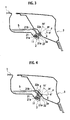
- FIG. 2 is an enlarged cross-sectional view along a line A-A of FIG. 1A, showing a state before such a lifting system back door is closed;
- FIG. 3 is an enlarged cross-sectional view along the line A-A of FIG 1A, showing a state where the lifting system back door is closed;
- FIG. 4 is an enlarged cross-sectional view along a line B-B of FIG. 1B, showing a state where such a lateral opening system back door is closed;
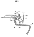
- FIG. 5 is an enlarged cross-sectional view along a line C-C of FIG. 1A, showing a state where the lifting system back door is closed;
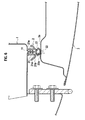
- FIG. 6 is an enlarged cross-sectional view along a line D-D of FIG. 1B, showing a state where the lateral opening system back door is closed;
- FIG. 7A is a view showing a state where a weatherstrip is attached onto a flange so that a hollow seal member can abut perpendicularly on an inner surface of the lateral opening system back door when the back door is closed;
- FIG. 7B is a view showing a state where the weatherstrip is attached onto a flange so that the hollow seal member can abut perpendicularly on an inner surface of the lifting system back door when the back door is closed;
- FIG. 8 is an enlarged cross-sectional view showing a state where a lifting system back door in a second embodiment is closed; and
- FIG. 9 is an enlarged cross-sectional view showing a state where a lateral opening system back door in the second embodiment is closed.
- A description will be made below in detail of specific embodiments to which the present invention is applied while referring to the drawings.
- A first embodiment is an example where a sealing structure of a back door opening according to the present invention is applied to a vehicle including a lifting system back door of FIG. 1A, in which a
back door 3 is lifted upward of the vehicle, and to a vehicle including a lateral opening system back door of FIG. 1 B, in whichback doors 3 are opened in the vehicle width direction. Note that the lateral opening system back door includes both of a so-called double-doored system (type of FIG. 1B) of individually opening and closing two back doors in the vehicle width direction and a system (not shown) of opening and closing one back door in the vehicle width direction. - In the sealing structure of the back door opening according to the first embodiment, as shown in FIG. 2 to FIG. 6, a
base member 21 of aweatherstrip 2 is engaged with aflange 11 formed along a back door opening of a body panel 1. In such a way, sealing property between the body panel 1 and theback door 3 is ensured when theback door 3 is closed by ahollow seal member 22 of theweatherstrip 2. - As shown in FIG. 2, the
base member 21 of the weatherstrip is formed into a substantial U-shape in cross section. Moreover, on opposite surfaces in an inside of thebase member 21, there are formed a plurality of retainingribs 21 a for inhibiting thebase member 21 from falling off from theflange 11 in such a manner that theretaining ribs 21a are engaged with theflange 11, and are thereby brought into press contact with theflange 11. - The
hollow seal member 22 of theweatherstrip 2 is formed into a pantograph shape (substantially rhombus shape) having aninclined protrusion 22a brought into elastic contact with a back doorinner surface 3a. Moreover, thehollow seal member 22 is folded by being pushed by theback door 3 while having reaction force allowing thehollow seal member 22 to be restored. Theinclined protrusion 22a acts to control a lying direction of thehollow seal member 22 when thehollow seal member 22 is pushed by the back doorinner surface 3a. Moreover, theinclined protrusion 22a acts to hermetically seal a gap caused between the back doorinner surface 3a and thehollow seal member 22 by unevenness in contact between theback door 3 and theweatherstrip 2. Theinclined protrusion 22a is formed so as to be directed to an outside (upward of a vehicle body) of the back door opening with respect to an attachment angle of theweatherstrip 2 onto theflange 11. In such a way, the collapse direction of thehollow seal member 22 can be made to be directed to the outside of the back door opening. - The attachment angle of the
weatherstrip 2 on an upper end edge of the back door opening is set within an inclination angle range θ between a first angle (0 degree as the horizontal direction along a line X in the vehicle fore-and-aft direction) and a second angle (predetermined angle made with respect to the line X in the vehicle fore-and-aft direction). The first angle is an angle in which theweatherstrip 2 is attached so that thehollow seal member 22 can abut perpendicularly on the back doorinner surface 3a when the lateral opening system back door shown in FIG. 1B is closed. The second angle is an angle in which theweatherstrip 2 is attached so that thehollow seal member 22 can abut perpendicularly on the back doorinner surface 3a when the lifting system back door shown in FIG. 1A is closed. - In the lateral opening system back door, the best sealing performance is obtained when the
weatherstrip 2 is attached at the angle of 0 degree as the horizontal direction. Meanwhile, in the lifting system back door, the best sealing performance is obtained when theweatherstrip 2 is attached to be inclined at 70 degrees. Heretofore, theweatherstrip 2 has been attached at 0 degree and 70 degrees in the lateral opening system back door and the lifting system back door, respectively. However, in the first embodiment of the present invention, the attachment angle of theweatherstrip 2 is set at an inclination angle of 35 degrees, which is just a middle between the first angle (0 degree) and the second angle (70 degrees), so that the sealing performance of theweatherstrip 2 can be ensured in both of the lateral opening system back door and the lifting system back door. - Moreover, on a side wall of the
base member 21 on a lying direction side of thehollow seal member 22, a lyingcontrol rib 21b that controls the lying of thehollow seal member 22 is formed integrally. The lyingcontrol rib 21 b is formed to be longer so that a tip end thereof can protrude to an outside of the collapsedhollow seal member 22. - Furthermore, as shown in FIG. 5, a construction is adopted, in which a fixing
part 41 for abumper 4 is formed at a position hidden by the lyingcontrol rib 21b in the body panel 1 on a lower end edge of the back door opening. The fixingpart 41 is, for example, a bolt and the like. - Next, a description will be made of functions and effects of the sealing structure of the back door opening according to the first embodiment.
- On the upper end edge of the back door opening, a seal mode as shown in FIG. 3 is formed in the case of the lifting system back door, and a seal mode as shown in FIG. 4 is formed in the case of the lateral opening system back door.
- First, in the lifting system back door, when the
back door 3 is closed, as shown in FIG. 3, the back doorinner surface 3a abuts on theinclined protrusion 22a in thehollow seal member 22 at the angle of 70 degrees with respect to theweatherstrip 2 with the attachment angle of 35 degrees. Then, thehollow seal member 22 is pushed by theback door 3, is folded properly with the reaction force allowing thehollow seal member 22 to be restored, and seals theback doors 3 by means of elastic force thereof. - Meanwhile, in the lateral opening system back door, when the
back door 3 is closed, as shown in FIG. 4, the back doorinner surface 3a abuts on theinclined protrusion 22a in thehollow seal member 22 at the angle of 0 degree as the horizontal direction with respect to theweatherstrip 2 with the attachment angle of 35 degrees. Then, thehollow seal member 22 is pushed by theback door 3, and is collapsed while being biased to the outside direction (upward direction of the vehicle body) of the back door opening. At this time, thehollow seal member 22 is collapsed so as to lie in the outside direction of the back door opening as shown by arrow E in FIG. 4. However, thehollow seal member 22 is supported by the lyingcontrol rib 21b formed integrally on thebase member 21, and is controlled from lying. Then, when theback door 3 is completely closed, the collapsedhollow seal member 22 seals theback door 3 by means of the elastic force thereof. - On the lower end edge of the back door opening, a seal mode between the
weatherstrip 2 and theback door 3 becomes the same seal mode as that on the upper end edge of the back door opening. However, as shown in FIG. 5, a cross-sectional shape of theweatherstrip 2 on the lower end edge becomes a shape turned upside down by 180 degrees from the upper end edge. - On a side edge of the back door opening, there is no large difference in approach angle of the
back door 3 to theweatherstrip 2 between the lifting system back door and the lateral opening system back door. Therefore, theback door 3 abuts on theweatherstrip 2 in the same way between both of the systems, and seal modes of both thereof become substantially the same. Specifically, in both of the case of the lifting system back door and the case of the lateral opening system back door, theback door 3 abuts on theweatherstrip 2 at substantially the same angle. Accordingly, as shown in FIG. 6, thehollow seal member 22 is collapsed perpendicularly to the back doorinner surface 3a. Then, when theback door 3 is completely closed, thehollow seal member 22 seals theback door 3 by means of elastic force when thehollow seal member 22 is collapsed in a direction perpendicular to a protruding direction of theflange 11. - As described above, in the sealing structure of the back door opening according to the first embodiment, the attachment angle of the
weatherstrip 2 is set at the inclination angle of 35 degrees, which is just the middle between the first angle (0 degree) and the second angle (70 degrees). In such a way, commonality can be provided to the sealing structure of the lifting system back door and the sealing structure of the lateral opening system back door. Therefore, an effect that it becomes possible to reduce manufacturing cost is obtained. - Moreover, the
inclined protrusion 22a is formed into a shape to be directed to the outside of the back door opening with respect to the attachment angle (35 degrees) of theweatherstrip 2, and the lyingcontrol rib 21b that controls the lying of thehollow seal member 22 is formed integrally on thebase member 21 on the lying direction side of thehollow seal member 22. In such a way, even if the attachment angle of theweatherstrip 2 is set at the inclination angle of 35 degrees, which is just the middle between the first angle (0 degree) and the second angle (70 degrees), it becomes possible to control the lying of thehollow seal member 22. - Furthermore, when the attachment angle of the
weatherstrip 2 is set at the inclination angle of 35 degrees, which is just the middle between the first angle (0 degree) and the second angle (70 degrees), a cross-sectional area of a water passage on the upper end edge of the opening is narrowed in the case of the lifting system back door. Therefore, there is an apprehension that, when theback door 3 is lifted, rainwater adhered onto an upper end surface of theback door 3 may flow into awater passage 5, overflow from thewater passage 5, and flow down into a vehicle cabin. However, in the first embodiment, on the side wall of thebase member 21 in theweatherstrip 2, the lyingcontrol rib 21b is formed, in which the tip end protrudes to the upward direction of the vehicle body more than the collapsedhollow seal member 22. In such a way, the cross-sectional area of the water passage can be ensured, and it becomes possible to prevent the water from flowing down into the vehicle cabin from the back door opening. - Moreover, in the first embodiment, the fixing
part 41 for thebumper 4 is provided at the position hidden by the lyingcontrol rib 21b in the body panel 1 on the lower end edge of the back door opening. In such a way, it becomes possible to allow the lyingcontrol rib 21b to function as a design part that covers and hides the fixingpart 41 for thebumper 4. - Next, a description will be made of a second embodiment to which the present invention is applied. In the second embodiment, the same constituent portions as those of the first embodiment will not be shown, or the same reference numerals will be added thereto to omit a description thereof, and a description will be made only of different points.
- In a sealing structure of a back door opening in the second embodiment, a portion provided with the
hollow seal member 22 and the lyingcontrol rib 21 is reversed to that in the structure of the first embodiment. Specifically, as shown in FIGS. 8 and 9, aninclined protrusion 22a of the second embodiment is formed toward an inside (downward direction of the vehicle body) of the back door opening with respect to the attachment angle (35 degrees) of theweatherstrip 2 on the contrary to theinclined protrusion 22a of the first embodiment, which is directed to the outside of the back door opening. Moreover, a lyingcontrol rib 21d is formed integrally on the side wall of thebase member 21 on the lying direction side of thehollow seal member 22. - In the sealing structure of the back door opening according to the second embodiment, as described above, the attachment angle of the
weatherstrip 2 is set at the inclination angle of 35 degrees, which is just the middle between the first angle (0 degree) and the second angle (70 degrees). In such a way, as in the first embodiment, the commonality can be provided to the sealing structure of the lifting system back door and the sealing structure of the lateral opening system back door. Therefore, the effect that it becomes possible to reduce the manufacturing cost is obtained. - Moreover, the construction is adopted, in which the
inclined protrusion 22a is formed into the mode to be directed to the inside of the back door opening with respect to the attachment angle (35 degrees) of theweatherstrip 2, and the lyingcontrol rib 21d that controls the lying of thehollow seal member 22 is formed integrally on thebase member 21 on the lying direction side of thehollow seal member 22. In such a way, even if the attachment angle of theweatherstrip 2 is set at the inclination angle of 35 degrees, which is just the middle between the first angle (0 degree) and the second angle (70 degrees), it becomes possible to control the lying of thehollow seal member 22. - The description has been made above of the first embodiment and the second embodiment, to which the present invention is applied, with reference to the drawings. However, the present invention is not limited to the above-described embodiments. For example, in the above-described first and second embodiments, the attachment angle of the
weatherstrip 2 is set at the inclination angle of 35 degrees, which is just the middle between the first angle (0 degree) suitable for the case of the lateral opening system back door and the second angle (70 degrees) suitable for the case of the lifting system back door. However, the attachment angle of theweatherstrip 2 just needs to be an inclination angle between the first angle (0 degree) and the second angle (70 degrees). It is most desirable that the attachment angle of theweatherstrip 2 be set at an inclination angle of 35 to 40 degrees. - Moreover, in the above-described first and second embodiments, the
hollow seal member 22 of theweatherstrip 2 is formed into the pantograph shape including theinclined protrusion 22a brought into elastic contact with the back doorinner surface 3a. However, a hollow shape of theseal member 22 is arbitrary. - The entire contents of
Japanese Patent Applications No. P2006-215499 No. P2007-162215 - Although the invention has been described above by reference to certain embodiments of the invention, the invention is not limited to the embodiments described above and modifications may become apparent to these skilled in the art, in light of the teachings herein. The scope of the invention is defined with reference to the following claims.
Claims (7)
- A sealing structure of a back door opening, comprising:a body panel (1) comprising a flange (11) formed along the back door opening; anda weatherstrip (2) attached onto the flange (11), the weatherstrip (2) comprising: a base member (21) engaged with the flange (11); and a hollow seal member (22) for ensuring sealing property between the body panel (1) and a lifting system back door (3) or a lateral opening system back door (3) when the back door (3) is closed,wherein an attachment angle of the weatherstrip (2) onto the flange (11) on an upper edge of the back door opening is set at an inclination angle between a first angle and a second angle, the first angle being an angle in which the weatherstrip (2) is attached so that the hollow seal member (22) can abut perpendicularly on a back door inner surface (3a) when the lateral opening system back door (3) is closed, and the second angle being an angle in which the weatherstrip (2) is attached so that the hollow seal member (22) can abut perpendicularly on the back door inner surface (3a) when the lifting system back door (3) is closed.
- A sealing structure of a back door opening according to claim 1,
wherein the first angle and the second angle are 0 degree and 70 degrees with respect to a line (X) in a vehicle fore-and-aft direction, respectively. - A sealing structure of a back door opening according to claim 2,
wherein the attachment angle of the weatherstrip (2) is within a range from 35 to 40 degrees with respect to the line (X) in the vehicle fore-and-aft direction. - A sealing structure of a back door opening according to any one of claims 1 to 3,
wherein an inclined protrusion (22a), which controls a lying direction (E) of the hollow seal member (22) when the hollow seal member (22) is pushed by the back door inner surface (3a), is formed on the hollow seal member (22), and
a lying control rib (21b), which controls lying of the hollow seal member (22), is provided integrally on the base member (21) on a lying direction side of the hollow seal member (22). - A sealing structure of a back door opening according to claim 4,
wherein the hollow seal member (22) is formed into a pantograph shape. - A sealing structure of a back door opening according to claim 4 or 5,
wherein the lying control rib (21b) is formed integrally on the base member (21) so that a tip end of the lying control rib (21b) can protrude to an outside of the hollow seal member (22) collapsed by the back door (3). - A sealing structure of a back door opening according to claim 6,
wherein a fixing part (41) for a bumper (4) is formed at a position hidden by the lying control rib (21b) in the body panel (1) on a lower end edge of the back door opening.
Applications Claiming Priority (2)
| Application Number | Priority Date | Filing Date | Title |
|---|---|---|---|
| JP2006215499 | 2006-08-08 | ||
| JP2007162215A JP4882885B2 (en) | 2006-08-08 | 2007-06-20 | Back door opening seal structure |
Publications (3)
| Publication Number | Publication Date |
|---|---|
| EP1886859A2 true EP1886859A2 (en) | 2008-02-13 |
| EP1886859A3 EP1886859A3 (en) | 2010-04-21 |
| EP1886859B1 EP1886859B1 (en) | 2011-04-20 |
Family
ID=38829193
Family Applications (1)
| Application Number | Title | Priority Date | Filing Date |
|---|---|---|---|
| EP07015202A Active EP1886859B1 (en) | 2006-08-08 | 2007-08-02 | Sealing structure of back door opening |
Country Status (3)
| Country | Link |
|---|---|
| EP (1) | EP1886859B1 (en) |
| JP (1) | JP4882885B2 (en) |
| DE (1) | DE602007013977D1 (en) |
Cited By (1)
| Publication number | Priority date | Publication date | Assignee | Title |
|---|---|---|---|---|
| US12059946B2 (en) | 2022-08-31 | 2024-08-13 | Nissan North America, Inc. | Vehicle roof assembly |
Families Citing this family (1)
| Publication number | Priority date | Publication date | Assignee | Title |
|---|---|---|---|---|
| CN106335447A (en) * | 2016-11-02 | 2017-01-18 | 张家港市隆旌汽车零部件有限公司 | Dustproof and waterproof elastic strip |
Citations (2)
| Publication number | Priority date | Publication date | Assignee | Title |
|---|---|---|---|---|
| JPH03281429A (en) | 1990-03-29 | 1991-12-12 | Kinugawa Rubber Ind Co Ltd | Weather strip for back door of vehicle |
| JPH0495574U (en) | 1991-01-10 | 1992-08-19 |
Family Cites Families (5)
| Publication number | Priority date | Publication date | Assignee | Title |
|---|---|---|---|---|
| JPS5826655A (en) * | 1981-08-10 | 1983-02-17 | Nissan Motor Co Ltd | Vehicle weather strip |
| JPS6088658A (en) * | 1983-10-19 | 1985-05-18 | Nissan Motor Co Ltd | Seal structure for back door |
| JP2616275B2 (en) * | 1991-05-08 | 1997-06-04 | 豊田合成株式会社 | Seal structure between outer panel and back door |
| DE19651733A1 (en) * | 1996-12-12 | 1998-06-18 | Metzeler Automotive Profiles | Heated rubber body |
| FR2860055B1 (en) * | 2003-09-23 | 2006-01-06 | Rehau Sa | TUBULAR PERIMETRIC JOINT TO BE MOUNTED ON THE BOTTOM OF AN OPENING, IN PARTICULAR OF AUTOMOBILE BODYWORK |
-
2007
- 2007-06-20 JP JP2007162215A patent/JP4882885B2/en active Active
- 2007-08-02 DE DE602007013977T patent/DE602007013977D1/en active Active
- 2007-08-02 EP EP07015202A patent/EP1886859B1/en active Active
Patent Citations (2)
| Publication number | Priority date | Publication date | Assignee | Title |
|---|---|---|---|---|
| JPH03281429A (en) | 1990-03-29 | 1991-12-12 | Kinugawa Rubber Ind Co Ltd | Weather strip for back door of vehicle |
| JPH0495574U (en) | 1991-01-10 | 1992-08-19 |
Cited By (1)
| Publication number | Priority date | Publication date | Assignee | Title |
|---|---|---|---|---|
| US12059946B2 (en) | 2022-08-31 | 2024-08-13 | Nissan North America, Inc. | Vehicle roof assembly |
Also Published As
| Publication number | Publication date |
|---|---|
| DE602007013977D1 (en) | 2011-06-01 |
| EP1886859A3 (en) | 2010-04-21 |
| JP2008062917A (en) | 2008-03-21 |
| JP4882885B2 (en) | 2012-02-22 |
| EP1886859B1 (en) | 2011-04-20 |
Similar Documents
| Publication | Publication Date | Title |
|---|---|---|
| US7648188B2 (en) | Glass run mounting structure | |
| CN108116202B (en) | Mounting structure of glass run for automobile door | |
| US8869457B2 (en) | Assembly structure of weather strip | |
| CN104442323B (en) | sealing strip | |
| US10583726B2 (en) | Glass run for automobile door | |
| CN108928223B (en) | Mounting structure of automobile glass guide groove | |
| JP2002067700A (en) | Glass run for automobile | |
| US10889172B2 (en) | Mounting portion structure of door mirror | |
| CN100544988C (en) | Sealing structure for rear door opening | |
| US5042200A (en) | Door glass run structure for automobile | |
| US7017305B2 (en) | Weather strip | |
| EP1886859B1 (en) | Sealing structure of back door opening | |
| CN107215189A (en) | The sealing structure of door weather strip | |
| JP2010052461A (en) | Glass run mounting structure | |
| JP5717784B2 (en) | Weather strip structure | |
| CN101012722A (en) | Glass run mounting assembly for a vehicle door | |
| JP2020147143A (en) | Seal structure for car doors | |
| US11511611B2 (en) | Weather strip assembly for door of bus | |
| JP2004359068A (en) | Sealing structure of sliding roof for automobile | |
| JP5204039B2 (en) | Door weather strip mounting structure | |
| JP2007320484A (en) | Door sash molding mounting structure | |
| JP4700325B2 (en) | Connected structure | |
| CN115701392A (en) | Tilting panel for contacting roof rail for better aerodynamic acoustic effect | |
| JP2001039168A (en) | Glass run deviation preventive structure of door for vehicle | |
| JP2007091172A (en) | Fitting structure for glass run |
Legal Events
| Date | Code | Title | Description |
|---|---|---|---|
| PUAI | Public reference made under article 153(3) epc to a published international application that has entered the european phase |
Free format text: ORIGINAL CODE: 0009012 |
|
| 17P | Request for examination filed |
Effective date: 20070829 |
|
| AK | Designated contracting states |
Kind code of ref document: A2 Designated state(s): AT BE BG CH CY CZ DE DK EE ES FI FR GB GR HU IE IS IT LI LT LU LV MC MT NL PL PT RO SE SI SK TR |
|
| AX | Request for extension of the european patent |
Extension state: AL BA HR MK YU |
|
| PUAL | Search report despatched |
Free format text: ORIGINAL CODE: 0009013 |
|
| AK | Designated contracting states |
Kind code of ref document: A3 Designated state(s): AT BE BG CH CY CZ DE DK EE ES FI FR GB GR HU IE IS IT LI LT LU LV MC MT NL PL PT RO SE SI SK TR |
|
| AX | Request for extension of the european patent |
Extension state: AL BA HR MK RS |
|
| RIC1 | Information provided on ipc code assigned before grant |
Ipc: B60J 10/08 20060101AFI20071227BHEP Ipc: B60R 13/06 20060101ALI20100318BHEP |
|
| GRAP | Despatch of communication of intention to grant a patent |
Free format text: ORIGINAL CODE: EPIDOSNIGR1 |
|
| RIC1 | Information provided on ipc code assigned before grant |
Ipc: B60R 13/06 20060101ALI20100816BHEP Ipc: B60J 10/08 20060101AFI20100816BHEP |
|
| AKX | Designation fees paid |
Designated state(s): DE FR GB |
|
| GRAS | Grant fee paid |
Free format text: ORIGINAL CODE: EPIDOSNIGR3 |
|
| GRAA | (expected) grant |
Free format text: ORIGINAL CODE: 0009210 |
|
| AK | Designated contracting states |
Kind code of ref document: B1 Designated state(s): DE FR GB |
|
| REG | Reference to a national code |
Ref country code: GB Ref legal event code: FG4D |
|
| REF | Corresponds to: |
Ref document number: 602007013977 Country of ref document: DE Date of ref document: 20110601 Kind code of ref document: P |
|
| REG | Reference to a national code |
Ref country code: DE Ref legal event code: R096 Ref document number: 602007013977 Country of ref document: DE Effective date: 20110601 |
|
| PLBE | No opposition filed within time limit |
Free format text: ORIGINAL CODE: 0009261 |
|
| STAA | Information on the status of an ep patent application or granted ep patent |
Free format text: STATUS: NO OPPOSITION FILED WITHIN TIME LIMIT |
|
| 26N | No opposition filed |
Effective date: 20120123 |
|
| REG | Reference to a national code |
Ref country code: DE Ref legal event code: R097 Ref document number: 602007013977 Country of ref document: DE Effective date: 20120123 |
|
| REG | Reference to a national code |
Ref country code: FR Ref legal event code: PLFP Year of fee payment: 10 |
|
| REG | Reference to a national code |
Ref country code: FR Ref legal event code: PLFP Year of fee payment: 11 |
|
| REG | Reference to a national code |
Ref country code: FR Ref legal event code: PLFP Year of fee payment: 12 |
|
| REG | Reference to a national code |
Ref country code: DE Ref legal event code: R084 Ref document number: 602007013977 Country of ref document: DE |
|
| REG | Reference to a national code |
Ref country code: GB Ref legal event code: 746 Effective date: 20231024 |
|
| PGFP | Annual fee paid to national office [announced via postgrant information from national office to epo] |
Ref country code: DE Payment date: 20250724 Year of fee payment: 19 |
|
| PGFP | Annual fee paid to national office [announced via postgrant information from national office to epo] |
Ref country code: GB Payment date: 20250725 Year of fee payment: 19 |
|
| PGFP | Annual fee paid to national office [announced via postgrant information from national office to epo] |
Ref country code: FR Payment date: 20250723 Year of fee payment: 19 |