EP1886813A2 - Plate replacing apparatus - Google Patents
Plate replacing apparatus Download PDFInfo
- Publication number
- EP1886813A2 EP1886813A2 EP07015686A EP07015686A EP1886813A2 EP 1886813 A2 EP1886813 A2 EP 1886813A2 EP 07015686 A EP07015686 A EP 07015686A EP 07015686 A EP07015686 A EP 07015686A EP 1886813 A2 EP1886813 A2 EP 1886813A2
- Authority
- EP
- European Patent Office
- Prior art keywords
- plate
- pressing unit
- support roller
- winding support
- replacing apparatus
- Prior art date
- Legal status (The legal status is an assumption and is not a legal conclusion. Google has not performed a legal analysis and makes no representation as to the accuracy of the status listed.)
- Withdrawn
Links
Images





Classifications
-
- B—PERFORMING OPERATIONS; TRANSPORTING
- B41—PRINTING; LINING MACHINES; TYPEWRITERS; STAMPS
- B41F—PRINTING MACHINES OR PRESSES
- B41F27/00—Devices for attaching printing elements or formes to supports
- B41F27/12—Devices for attaching printing elements or formes to supports for attaching flexible printing formes
- B41F27/1206—Feeding to or removing from the forme cylinder
-
- B—PERFORMING OPERATIONS; TRANSPORTING
- B41—PRINTING; LINING MACHINES; TYPEWRITERS; STAMPS
- B41P—INDEXING SCHEME RELATING TO PRINTING, LINING MACHINES, TYPEWRITERS, AND TO STAMPS
- B41P2227/00—Mounting or handling printing plates; Forming printing surfaces in situ
- B41P2227/60—Devices for transferring printing plates
- B41P2227/62—Devices for introducing printing plates
Definitions
- the present invention relates to a plate replacing apparatus included in a printing press, and more particularly, to a plate replacing apparatus that winds a plate around a plate cylinder.
- the roller needs to have a diameter at least a predetermined length. Therefore, the roller interferes with a vice of the plate. In other words, the roller cannot firmly press a trailing end of the plate around the vice. As a result, the plate is not wound around the plate cylinder precisely. To solve the problem, a portion to be pressed by the roller is extended, or the vice is notched so that the roller can firmly press the plate to its trailing end. In a case in which the vice is notched, however, the stiffness may drop insufficiently.
- a plate replacing apparatus includes a plate-winding support roller that presses a plate on a plate cylinder and a plate pressing unit that rotates around the plate-winding support roller and thereby pressing a trailing end of the plate in an edge portion of the plate pressing unit.
- the plate pressing unit presses the plate in a position in front of a lower tooth of a vice built in the plate cylinder.
- Fig. 1 is a side view of a printing press 1 according to an embodiment of the present invention, including a plate replacing apparatus.
- the printing press 1 includes a feeding unit 6, printing units 2, 3, 4, and 5, and a delivery unit 7.
- the feeding unit 6 feeds paper to be printed thereon to the printing unit.
- the printing units 2, 3, 4, and 5 respectively print an image in different colors, such as in cyan, magenta, yellow, and black, on the paper fed from the feeding unit 6 by overlapping each color sequentially.
- the printed paper is output by the delivery unit 7.
- Each of the printing units 2, 3, 4, and 5 respectively includes a number of rollers, such as a plate cylinder and an impression cylinder, those required for printing. These rollers are covered by a protective cover 8.
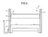
- Fig. 2 is a schematic diagram of the protective cover 8.
- the protective cover 8 is separated into an upper portion 13, a middle portion 14, and a lower portion 15. Both ends of the portions 13 to 15 are coupled to rectangular column-shaped frames 16 that are building frames of each of the printing units 2 to 5 (see Fig. 3).
- the frames 16 are covered by covers 11 and 12 respectively.
- Fig. 3 is a schematic diagram of the protective cover 8 when the upper portion 13 rotates.
- the upper portion 13 serves as the plate replacing apparatus.
- an old-plate removing slot 21 and a new-plate inserting slot 22 are provided on top of the upper portion 13.
- the upper portion 13 is configured to rotate around a rotation shaft 20 and slant at a predetermined angle with respect to the middle portion 14 and the lower portion 15.
- a plate-winding support roller 23 is provided at the end of the upper portion 13. The plate-winding support roller 23 presses a new plate on a plate cylinder (not shown), and supports the new plate to be wound around the plate cylinder. Except when a plate is to be replaced, the upper portion 13 serves as an upper structure of the protective cover 8.
- Fig. 4 is an enlarged side view of a plate cylinder 31 and the plate-winding support roller 23.
- a plate 32 which is gripped by a gripper-end side vice 34 built in the plate cylinder 31, is pressed on the plate cylinder 31 by the plate-winding support roller 23.
- a width of the plate-winding support roller 23 is approximately the same as that of the plate cylinder 31.
- the plate 32 rotates around the plate cylinder 31 by being pressed by the plate-winding support roller 23, and eventually is held by a trailing-end side vice 33 built in the plate cylinder 31.
- a plate pressing unit 35 is provided on the plate-winding support roller 23.
- the plate pressing unit 35 rotates around the plate-winding support roller 23 across the full width of the plate-winding support roller 23, and an end portion 35a of the plate pressing unit 35 presses a trailing end of the plate.
- the end portion 35a of the plate pressing unit 35 presses the plate 32 that is located in front of a lower tooth 36 of the vice 33 until the trailing-end side vice 33 grips the plate 32.
- a main body 38 of the trailing-end side vice 33 is configured to move linearly in a direction of an arrow 39 to pull the plate 32 by holding the plate 32.
- the plate 32 can be pressed by the plate-winding support roller 23, but it is not possible to firmly press a portion of the plate 32 which is close to the trailing-end side vice 33 because the plate-winding support roller 23 has a predetermined length of a diameter. Consequently, the plate 32 cannot be wound around the plate cylinder 31 precisely. If a portion close to the trailing-end side vice 33 is extended to solve the problem, a space for a picture image in the plate 32.is reduced.
- the plate pressing unit 35 is provided on the plate-winding support roller 23, and thus it is possible to firmly press the portion of the plate 32 which is geometrically close to a holding unit 37 of the trailing-end side vice 33. Therefore, the plate-winding precision can be maintained, and also a longitudinal length of the picture image can be maximized. Furthermore, the plate 32 is pressed in accordance with the rotation of the plate pressing unit 35, so that even if a plate has a high stiffness and is not sufficiently pressed by the plate-winding support roller 23, the plate can be pressed on the lower tooth 36 of the trailing-end side vice 33 without any force. Incidentally, the plate pressing unit 35 needs not have an L-shape as shown in the drawing. The plate pressing unit 35 can have any shape as long as the end portion of the plate pressing unit 35 can press the plate in accordance with the rotation of the plate pressing unit 35.
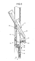
- Fig. 5 is a side view of a plate replacing apparatus C.
- the plate replacing apparatus C which is the upper portion 13 of the protective cover 8, rotates so that an outlet of a new-plate insertion path and an inlet of an old-plate removal path 46 move close to the plate cylinder 31.
- the plate-winding support roller 23 and the plate pressing unit 35 capable of rotating around the plate-winding support roller 23 are arranged at the end of the plate replacing apparatus C.
- the plate pressing unit 35 is controlled rotating and pressing around the plate-winding support roller 23 by a link mechanism L that is coupled to an air cylinder 41 as a translatory actuator.
- the main-body side of an end portion 47 of the air cylinder 41 is arranged inside the protective cover 8.
- the air cylinder 41 is contained inside the protective cover 8 together with the plate-winding support roller 23 and the plate pressing unit 35.
- the plate pressing unit 35 and the plate-winding support roller 23 do not interfere with rollers, such as the plate cylinder and a blanket cylinder, inside the printing units.
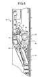
- Figs. 6 to 8 are side views for explaining a movement of the link mechanism.
- the plate replacing apparatus C rotates at an angle ⁇ 1 with respect to the protective cover 8.
- the plate-winding support roller 23 which is biased in a direction towards the plate cylinder by a spring or the like, rotates in a direction of an arrow 51, which is an opposite direction against the bias, because of a reaction of pressing on the plate cylinder.
- the rod 45 of the air cylinder 41 is contracted, a second joint 42 between the arms 43 and 44 comes down, and the arms 43 and 44 those in a state as shown in Fig. 5 are folded.
- the plate pressing unit 35 rotates counterclockwise, and locates a position where the plate pressing unit 35 contacts neither the old plate nor the new plate regardless of an angle of the plate replacing apparatus C. Therefore, the plates can be prevented from being scratched by the plate pressing unit 35.
- Fig. 7 is a side view of the plate replacing apparatus C when the plate pressing unit 35 is contained inside the protective cover 8.
- Fig. 8 is an enlarged view of a region S shown in Fig. 7.
- the arm 44 guided by the plate pressing unit 35 which is rotatably provided on the shaft of the plate-winding support roller 23, is folded by sliding a slide hole 52 of the arm 43.
- the arms 43 and 44 are partially overlapped with each other.
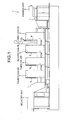
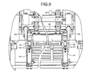
- Fig. 9 is a front view of the plate replacing apparatus C in a state shown in Fig. 8.
- the plate replacing apparatus C contained inside the protective cover 8 stores therein a new plate that is inserted in advance until the new plate is wound around the plate cylinder. Therefore, it is necessary to secure as much space as possible in a thickness direction of the plate replacing apparatus C so that the new plate can be inserted and stored therein.
- the plate pressing unit 35 when the plate pressing unit 35 is contained inside the protective cover 8, the plate pressing unit 35 is configured to rotate in the same direction as that the plate is pressed by the link mechanism L (in a case shown in Fig. 8, in a clockwise direction), and to stop rotating at a certain rotational position (at a position shown in Fig. 8) where the plate pressing unit 35 does not contact any other members inside the protective cover 8.
- the rotation of the plate pressing unit 35 is controlled by the link mechanism L.
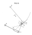
- Fig. 10 is a diagram for explaining a movement of the link mechanism.
- the rotation shaft 20 of the protective cover 8 in a state shown in Fig. 6 is coupled to the plate-winding support roller 23.
- the plate-winding support roller 23 is further coupled to the plate pressing unit 35.
- the plate pressing unit 35 is further coupled to the second joint 42 between the arms 43 and 44.
- the link mechanism L in which the rod 45 of the air cylinder 41 is contracted acts in accordance with the rotation of the plate replacing apparatus C.
- the force F1 can be considered as a resultant of a force F1X in a direction along the arm 44 (hereinafter, an "X direction") and a force F1Y in a direction perpendicular to the X direction (hereinafter, a "Y direction").
- the shaft 53 When the force F1Y as a component force of the resultant is applied to the shaft 53 of the plate pressing unit 35, the shaft 53 receives a force F2 in a direction to rotate clockwise because the shaft 53 is constrained by an orbit 57 of the plate-winding support roller 23.
- Fig. 11 is a schematic diagram for explaining how arms are folded and the plate pressing unit moves.
- a shaft 53' of the plate pressing unit 35 is located at a position where the plate pressing unit 35 further rotates clockwise from a position shown in Fig. 6 or 10.
- the plate pressing unit 35 further rotates clockwise from the position P.
- a shaft 53" of the plate pressing unit 35 is located above the plate-winding support roller 23 (in a case shown in Fig. 11, in a direction of 10 o'clock). At this time, the plate pressing unit 35 is in a state shown in Fig. 7 or 8.
- the second joint 42 between the arms 43 and 44 slides in the hole 52 of the arm 43, and moves from a position 42' to a position 42".
- the arm 44 is folded until the arms 43 and 44 are partially overlapped with each other (as indicated by arms 43" and 44").
- the plate pressing unit 35 when contained inside the protective cover 8, the plate pressing unit 35 rotates clockwise, but if space allows, there is no need to be limited to rotate clockwise specifically.
- the plate pressing unit 35 can be arranged as desired by changing lengths of the arms 43 and 44 and a position of the shaft 53 of the plate pressing unit 35 appropriately.
- the plate pressing unit can press close to a trailing end of a plate.
- a longitudinal length of a picture image can be maximized close to a trailing end of the plate.
Landscapes
- Supply, Installation And Extraction Of Printed Sheets Or Plates (AREA)
- Perforating, Stamping-Out Or Severing By Means Other Than Cutting (AREA)
Abstract
Description
- The present invention relates to a plate replacing apparatus included in a printing press, and more particularly, to a plate replacing apparatus that winds a plate around a plate cylinder.
- In a conventional plate replacing apparatus included in a printing press as disclosed in
Japanese Patent No. 2956021 - To ensure the stiffness required for pressing the plate, the roller needs to have a diameter at least a predetermined length. Therefore, the roller interferes with a vice of the plate. In other words, the roller cannot firmly press a trailing end of the plate around the vice. As a result, the plate is not wound around the plate cylinder precisely. To solve the problem, a portion to be pressed by the roller is extended, or the vice is notched so that the roller can firmly press the plate to its trailing end. In a case in which the vice is notched, however, the stiffness may drop insufficiently.
- It is an object of the present invention to at least partially solve the problems in the conventional technology.
- A plate replacing apparatus according to one aspect of the present invention includes a plate-winding support roller that presses a plate on a plate cylinder and a plate pressing unit that rotates around the plate-winding support roller and thereby pressing a trailing end of the plate in an edge portion of the plate pressing unit. The plate pressing unit presses the plate in a position in front of a lower tooth of a vice built in the plate cylinder.
- The above and other objects, features, advantages and technical and industrial significance of this invention will be better understood by reading the following detailed description of presently preferred embodiments of the invention, when considered in connection with the accompanying drawings.
-
- Fig. 1 is a side view of a printing press according to an embodiment of the present invention, including a plate replacing apparatus;
- Fig. 2 is a schematic diagram of a protective cover of the printing press shown in Fig. 1;
- Fig. 3 is a schematic diagram of the protective cover shown in Fig. 2 when an upper portion of the protective cover rotates;
- Fig. 4 is a side view of a plate cylinder and a plate-winding support roller;
- Fig. 5 is a side view of the plate replacing apparatus;
- Fig. 6 is a side view of the plate replacing apparatus for explaining a movement of a link mechanism;
- Fig. 7 is a side view of a plate pressing unit contained inside the protective cover;
- Fig. 8 is an enlarged view of the plate pressing unit;
- Fig. 9 is a front view of the plate replacing apparatus in a state shown in Fig. 8;
- Fig. 10 is a schematic diagram for explaining a movement of the link mechanism; and
- Fig. 11 is a schematic diagram for explaining how arms , are folded and the plate pressing unit moves.
- Embodiments of the present invention are explained in detail below with reference to the accompanying drawings. The present invention is not limited to the embodiments. Incidentally, components capable of being easily conceived by those skilled in the art are to be employed in the embodiments.
- Fig. 1 is a side view of a
printing press 1 according to an embodiment of the present invention, including a plate replacing apparatus. Theprinting press 1 includes afeeding unit 6,printing units delivery unit 7. Thefeeding unit 6 feeds paper to be printed thereon to the printing unit. Theprinting units feeding unit 6 by overlapping each color sequentially. The printed paper is output by thedelivery unit 7. Each of theprinting units protective cover 8. - Fig. 2 is a schematic diagram of the
protective cover 8. Theprotective cover 8 is separated into anupper portion 13, amiddle portion 14, and alower portion 15. Both ends of theportions 13 to 15 are coupled to rectangular column-shaped frames 16 that are building frames of each of theprinting units 2 to 5 (see Fig. 3). Theframes 16 are covered bycovers - Fig. 3 is a schematic diagram of the
protective cover 8 when theupper portion 13 rotates. Theupper portion 13 serves as the plate replacing apparatus. As shown in Fig. 3, an old-plate removing slot 21 and a new-plate inserting slot 22 are provided on top of theupper portion 13. - The
upper portion 13 is configured to rotate around arotation shaft 20 and slant at a predetermined angle with respect to themiddle portion 14 and thelower portion 15. A plate-windingsupport roller 23 is provided at the end of theupper portion 13. The plate-windingsupport roller 23 presses a new plate on a plate cylinder (not shown), and supports the new plate to be wound around the plate cylinder. Except when a plate is to be replaced, theupper portion 13 serves as an upper structure of theprotective cover 8. - Fig. 4 is an enlarged side view of a
plate cylinder 31 and the plate-windingsupport roller 23. Aplate 32, which is gripped by a gripper-end side vice 34 built in theplate cylinder 31, is pressed on theplate cylinder 31 by the plate-windingsupport roller 23. Incidentally, a width of the plate-windingsupport roller 23 is approximately the same as that of theplate cylinder 31. Theplate 32 rotates around theplate cylinder 31 by being pressed by the plate-windingsupport roller 23, and eventually is held by a trailing-end side vice 33 built in theplate cylinder 31. - A
plate pressing unit 35 is provided on the plate-windingsupport roller 23. Theplate pressing unit 35 rotates around the plate-windingsupport roller 23 across the full width of the plate-windingsupport roller 23, and anend portion 35a of theplate pressing unit 35 presses a trailing end of the plate. Specifically, theend portion 35a of theplate pressing unit 35 presses theplate 32 that is located in front of alower tooth 36 of thevice 33 until the trailing-end side vice 33 grips theplate 32. Incidentally, to prevent a deflection or a displacement of theplate 32 as much as possible, it is preferable that amain body 38 of the trailing-end side vice 33 is configured to move linearly in a direction of anarrow 39 to pull theplate 32 by holding theplate 32. - If it is assumed that the
plate pressing unit 35 is not provided on the plate-windingsupport roller 23, theplate 32 can be pressed by the plate-windingsupport roller 23, but it is not possible to firmly press a portion of theplate 32 which is close to the trailing-end side vice 33 because the plate-windingsupport roller 23 has a predetermined length of a diameter. Consequently, theplate 32 cannot be wound around theplate cylinder 31 precisely. If a portion close to the trailing-end side vice 33 is extended to solve the problem, a space for a picture image in the plate 32.is reduced. - According to the embodiment, the
plate pressing unit 35 is provided on the plate-windingsupport roller 23, and thus it is possible to firmly press the portion of theplate 32 which is geometrically close to aholding unit 37 of the trailing-end side vice 33. Therefore, the plate-winding precision can be maintained, and also a longitudinal length of the picture image can be maximized. Furthermore, theplate 32 is pressed in accordance with the rotation of theplate pressing unit 35, so that even if a plate has a high stiffness and is not sufficiently pressed by the plate-windingsupport roller 23, the plate can be pressed on thelower tooth 36 of the trailing-end side vice 33 without any force. Incidentally, theplate pressing unit 35 needs not have an L-shape as shown in the drawing. Theplate pressing unit 35 can have any shape as long as the end portion of theplate pressing unit 35 can press the plate in accordance with the rotation of theplate pressing unit 35. - Fig. 5 is a side view of a plate replacing apparatus C. As described above, when a plate is to be replaced, the plate replacing apparatus C, which is the
upper portion 13 of theprotective cover 8, rotates so that an outlet of a new-plate insertion path and an inlet of an old-plate removal path 46 move close to theplate cylinder 31. The plate-windingsupport roller 23 and theplate pressing unit 35 capable of rotating around the plate-windingsupport roller 23 are arranged at the end of the plate replacing apparatus C. Theplate pressing unit 35 is controlled rotating and pressing around the plate-windingsupport roller 23 by a link mechanism L that is coupled to anair cylinder 41 as a translatory actuator. - As shown in Fig. 5, when a
rod 45 of theair cylinder 41 is extended, a joint (the second joint) betweenarms plate pressing unit 35 coupled to thearm 44 is constrained to move on an orbit centering around a shaft of the plate-windingsupport roller 23. Therefore, when pushed up by thearm 44, the joint is pressed towards thelower tooth 36 of the trailing-end side vice 33 (see Fig. 4). - The main-body side of an end portion 47 of the
air cylinder 41 is arranged inside theprotective cover 8. When the link mechanism L is folded, theair cylinder 41 is contained inside theprotective cover 8 together with the plate-windingsupport roller 23 and theplate pressing unit 35. For example, by enabling theprotective cover 8 to open/close up and down, at the time of maintenance of the printing units, theplate pressing unit 35 and the plate-windingsupport roller 23 do not interfere with rollers, such as the plate cylinder and a blanket cylinder, inside the printing units. - Figs. 6 to 8 are side views for explaining a movement of the link mechanism. As shown in Fig. 6, when a new plate is inserted, the plate replacing apparatus C rotates at an angle θ1 with respect to the
protective cover 8. At this time, the plate-windingsupport roller 23, which is biased in a direction towards the plate cylinder by a spring or the like, rotates in a direction of anarrow 51, which is an opposite direction against the bias, because of a reaction of pressing on the plate cylinder. As therod 45 of theair cylinder 41 is contracted, a second joint 42 between thearms arms plate pressing unit 35 rotates counterclockwise, and locates a position where theplate pressing unit 35 contacts neither the old plate nor the new plate regardless of an angle of the plate replacing apparatus C. Therefore, the plates can be prevented from being scratched by theplate pressing unit 35. - Fig. 7 is a side view of the plate replacing apparatus C when the
plate pressing unit 35 is contained inside theprotective cover 8. Fig. 8 is an enlarged view of a region S shown in Fig. 7. As shown in Figs. 7 and 8, when the plate replacing apparatus C rotates and is contained inside theprotective cover 8 by contracting therod 45 of theair cylinder 41, thearm 44 guided by theplate pressing unit 35, which is rotatably provided on the shaft of the plate-windingsupport roller 23, is folded by sliding aslide hole 52 of thearm 43. At this time, thearms - Fig. 9 is a front view of the plate replacing apparatus C in a state shown in Fig. 8. As shown in Fig. 9, the plate replacing apparatus C contained inside the
protective cover 8 stores therein a new plate that is inserted in advance until the new plate is wound around the plate cylinder. Therefore, it is necessary to secure as much space as possible in a thickness direction of the plate replacing apparatus C so that the new plate can be inserted and stored therein. - According to the embodiment, when the
plate pressing unit 35 is contained inside theprotective cover 8, theplate pressing unit 35 is configured to rotate in the same direction as that the plate is pressed by the link mechanism L (in a case shown in Fig. 8, in a clockwise direction), and to stop rotating at a certain rotational position (at a position shown in Fig. 8) where theplate pressing unit 35 does not contact any other members inside theprotective cover 8. The rotation of theplate pressing unit 35 is controlled by the link mechanism L. - Fig. 10 is a diagram for explaining a movement of the link mechanism. As shown in Fig. 10, the
rotation shaft 20 of theprotective cover 8 in a state shown in Fig. 6 is coupled to the plate-windingsupport roller 23. The plate-windingsupport roller 23 is further coupled to theplate pressing unit 35. Theplate pressing unit 35 is further coupled to the second joint 42 between thearms rod 45 of theair cylinder 41 is contracted acts in accordance with the rotation of the plate replacing apparatus C. - When the plate-winding
support roller 23 rotates in a direction of anarrow 56, a force F1 applied to the plate-windingsupport roller 23 is transmitted to ashaft 53 of theplate pressing unit 35 that is rotatably provided on the plate-windingsupport roller 23. The force F1 can be considered as a resultant of a force F1X in a direction along the arm 44 (hereinafter, an "X direction") and a force F1Y in a direction perpendicular to the X direction (hereinafter, a "Y direction"). When the force F1Y as a component force of the resultant is applied to theshaft 53 of theplate pressing unit 35, theshaft 53 receives a force F2 in a direction to rotate clockwise because theshaft 53 is constrained by anorbit 57 of the plate-windingsupport roller 23. - Fig. 11 is a schematic diagram for explaining how arms are folded and the plate pressing unit moves. At a position P, a shaft 53' of the
plate pressing unit 35 is located at a position where theplate pressing unit 35 further rotates clockwise from a position shown in Fig. 6 or 10. At a position Q, theplate pressing unit 35 further rotates clockwise from the position P. When the plate replacing apparatus C is at the position Q, ashaft 53" of theplate pressing unit 35 is located above the plate-winding support roller 23 (in a case shown in Fig. 11, in a direction of 10 o'clock). At this time, theplate pressing unit 35 is in a state shown in Fig. 7 or 8. Incidentally, the second joint 42 between thearms hole 52 of thearm 43, and moves from a position 42' to aposition 42". In the event, thearm 44 is folded until thearms arms 43" and 44"). - In the above embodiment, when contained inside the
protective cover 8, theplate pressing unit 35 rotates clockwise, but if space allows, there is no need to be limited to rotate clockwise specifically. Theplate pressing unit 35 can be arranged as desired by changing lengths of thearms shaft 53 of theplate pressing unit 35 appropriately. - According to an aspect of the present invention, the plate pressing unit can press close to a trailing end of a plate. Thus, a longitudinal length of a picture image can be maximized close to a trailing end of the plate.
- Although the invention has been described with respect to specific embodiments for a complete and clear disclosure, the appended claims are not to be thus limited but are to be construed as embodying all modifications and alternative constructions that may occur to one skilled in the art that fall within the teaching herein set forth.
Claims (5)
- A plate replacing apparatus comprising:a plate-winding support roller (23) that presses a plate on a plate cylinder; anda plate pressing unit (35) that rotates around the plate-winding support roller (23) and thereby pressing a trailing end of the plate in an edge portion of the plate pressing unit (35), whereinthe plate pressing unit (35) presses the plate in a position in front of a lower tooth of a vice built in the plate cylinder.
- The plate replacing apparatus according to claim 1, wherein rotating of the plate pressing unit (35) around the plate-winding support roller (23) and pressing of the plate pressing unit (35) on the plate are controlled by a link mechanism (L) to which a translatory actuator is coupled.
- The plate replacing apparatus according to claim 2, wherein
the link mechanism (L) applies a two-joint link mechanism to the plate pressing unit (35) that rotates around a shaft of the plate-winding support roller (23), and
a main body side of an end portion of the translatory actuator, which is coupled to a second joint of the link mechanism (L), is arranged inside a protective cover. - The plate replacing apparatus according to claim 2 or 3, wherein
when not replacing the plate, the link mechanism (L) is folded, and the plate pressing unit (35) is contained inside a protective cover of a main body of the apparatus together with the plate-winding support roller (23), and
when the plate pressing unit (35) is contained inside the protective cover, the plate pressing unit (35) rotates in a same direction as a direction when the plate is pressed by an action of the link mechanism (L), and stops rotating at a rotational position where the plate pressing unit (35) does not contact other members inside the protective cover. - The plate replacing apparatus according to any one of claims 1 to 4, wherein the plate replacing apparatus is built in a protective cover, rotates and moves close to the plate cylinder when a plate is to be replaced, and includes the plate-winding support roller (23) and the plate pressing unit (35) in its distal end.
Applications Claiming Priority (1)
| Application Number | Priority Date | Filing Date | Title |
|---|---|---|---|
| JP2006220298A JP4800148B2 (en) | 2006-08-11 | 2006-08-11 | Plate changer |
Publications (2)
| Publication Number | Publication Date |
|---|---|
| EP1886813A2 true EP1886813A2 (en) | 2008-02-13 |
| EP1886813A3 EP1886813A3 (en) | 2011-06-22 |
Family
ID=38686845
Family Applications (1)
| Application Number | Title | Priority Date | Filing Date |
|---|---|---|---|
| EP07015686A Withdrawn EP1886813A3 (en) | 2006-08-11 | 2007-08-09 | Plate replacing apparatus |
Country Status (4)
| Country | Link |
|---|---|
| US (1) | US20080035001A1 (en) |
| EP (1) | EP1886813A3 (en) |
| JP (1) | JP4800148B2 (en) |
| CN (1) | CN101121313B (en) |
Families Citing this family (2)
| Publication number | Priority date | Publication date | Assignee | Title |
|---|---|---|---|---|
| CN102975487B (en) * | 2012-12-24 | 2014-08-06 | 河北海贺胜利印刷机械集团有限公司 | Preloading platform for changing plate of post-press equipment |
| CN105291580B (en) * | 2015-11-25 | 2017-08-18 | 高斯图文印刷系统(中国)有限公司 | A kind of automatic plate change device of printing machine |
Family Cites Families (16)
| Publication number | Priority date | Publication date | Assignee | Title |
|---|---|---|---|---|
| EP0411731B1 (en) * | 1989-08-04 | 1995-11-29 | Komori Corporation | Plate-lockup apparatus for sheet-fed press |
| JP2844539B2 (en) * | 1989-12-15 | 1999-01-06 | 株式会社小森コーポレーション | Plate holding device for printing press |
| JP3030573B2 (en) * | 1991-05-30 | 2000-04-10 | 株式会社小森コーポレーション | Plate mounting device on plate cylinder |
| JP2590784Y2 (en) * | 1991-06-06 | 1999-02-17 | 株式会社 小森コーポレーション | Plate supply device for printing press |
| JP2570485Y2 (en) * | 1991-06-24 | 1998-05-06 | 株式会社小森コーポレーション | Plate changing device for printing press |
| JPH0577401A (en) * | 1991-09-19 | 1993-03-30 | Akiyama Insatsuki Seizo Kk | Printing plate mounting/dismounting device of printer |
| DE4214207C1 (en) * | 1992-04-30 | 1993-07-22 | Man Roland Druckmaschinen Ag, 6050 Offenbach, De | |
| DE19505630A1 (en) * | 1995-02-18 | 1996-08-22 | Roland Man Druckmasch | Device for changing printing plates |
| DE19639800C1 (en) * | 1996-09-27 | 1998-02-05 | Kba Planeta Ag | Positioning free end of printing plate fixed at its leading edge |
| JPH1120131A (en) * | 1997-07-03 | 1999-01-26 | Ryobi Ltd | Press plate gripper for printer |
| JP2000094642A (en) * | 1998-09-21 | 2000-04-04 | Ryobi Ltd | Auxiliary apparats for mounting press plate of printer |
| JP4625559B2 (en) * | 1999-09-17 | 2011-02-02 | 株式会社小森コーポレーション | Printer |
| DE10051367B4 (en) * | 1999-11-09 | 2012-10-04 | Heidelberger Druckmaschinen Ag | folding device |
| US6792860B2 (en) * | 2000-05-17 | 2004-09-21 | Koenig & Bauer Aktiengesellschaft | Method and device for pressing a packing against a cylinder |
| DE10306492B4 (en) * | 2002-03-21 | 2006-10-19 | Heidelberger Druckmaschinen Ag | Pressing device of a printing or varnishing machine |
| JP2005297440A (en) * | 2004-04-14 | 2005-10-27 | Dainippon Screen Mfg Co Ltd | Printer |
-
2006
- 2006-08-11 JP JP2006220298A patent/JP4800148B2/en active Active
-
2007
- 2007-07-23 CN CN2007101369263A patent/CN101121313B/en not_active Expired - Fee Related
- 2007-08-02 US US11/833,028 patent/US20080035001A1/en not_active Abandoned
- 2007-08-09 EP EP07015686A patent/EP1886813A3/en not_active Withdrawn
Also Published As
| Publication number | Publication date |
|---|---|
| JP4800148B2 (en) | 2011-10-26 |
| EP1886813A3 (en) | 2011-06-22 |
| CN101121313A (en) | 2008-02-13 |
| JP2008044166A (en) | 2008-02-28 |
| US20080035001A1 (en) | 2008-02-14 |
| CN101121313B (en) | 2010-08-25 |
Similar Documents
| Publication | Publication Date | Title |
|---|---|---|
| EP1818180B1 (en) | Sheet feeding apparatus and recording apparatus | |
| USRE40202E1 (en) | Ink ribbon cassette for thermal transfer printer | |
| EP1918117A2 (en) | Rolled sheet support mechanism and printer | |
| EP1826162A2 (en) | Sheet tray device and image forming apparatus having the street tray device | |
| EP1882589A2 (en) | Printing press | |
| EP0894640A2 (en) | Printer apparatus | |
| US7543809B2 (en) | Sheet tray device and image forming apparatus having the sheet tray device | |
| KR101253798B1 (en) | Platen supporting mechanism and writing device | |
| US20080035001A1 (en) | Plate replacing apparatus | |
| US9878563B2 (en) | Printer | |
| JP4670466B2 (en) | Platen gap adjusting device, printing device, and combined processing device | |
| EP1826017A2 (en) | Head support structure, printing device, thermally activating device, and printer | |
| US7452145B2 (en) | Hinge structure for paper container in a printer | |
| CN213891698U (en) | Full rotary press convenient to change relief roller | |
| JP4819536B2 (en) | Cassettes and printers | |
| JP4494270B2 (en) | Label printer | |
| JP4740314B2 (en) | Web offset printing machine with pivoted tacker | |
| JP2006036515A (en) | Roll paper support device | |
| JP2003165653A (en) | Bearing device and printing device for winding roller | |
| US11945244B2 (en) | Cartridge | |
| JP3223502B2 (en) | Automatic paper feeder | |
| JP4836686B2 (en) | Plate changer for printing machine | |
| JP3704815B2 (en) | Decurling device in image forming apparatus | |
| JP2008044210A (en) | Plate holding device and printing machine | |
| JP2002347290A (en) | Printer |
Legal Events
| Date | Code | Title | Description |
|---|---|---|---|
| PUAI | Public reference made under article 153(3) epc to a published international application that has entered the european phase |
Free format text: ORIGINAL CODE: 0009012 |
|
| AK | Designated contracting states |
Kind code of ref document: A2 Designated state(s): AT BE BG CH CY CZ DE DK EE ES FI FR GB GR HU IE IS IT LI LT LU LV MC MT NL PL PT RO SE SI SK TR |
|
| AX | Request for extension of the european patent |
Extension state: AL BA HR MK YU |
|
| RAP1 | Party data changed (applicant data changed or rights of an application transferred) |
Owner name: MITSUBISHI HEAVY INDUSTRIES PRINTING & PACKAGING M |
|
| PUAL | Search report despatched |
Free format text: ORIGINAL CODE: 0009013 |
|
| AK | Designated contracting states |
Kind code of ref document: A3 Designated state(s): AT BE BG CH CY CZ DE DK EE ES FI FR GB GR HU IE IS IT LI LT LU LV MC MT NL PL PT RO SE SI SK TR |
|
| AX | Request for extension of the european patent |
Extension state: AL BA HR MK RS |
|
| AKY | No designation fees paid | ||
| REG | Reference to a national code |
Ref country code: DE Ref legal event code: R108 Effective date: 20120229 |
|
| STAA | Information on the status of an ep patent application or granted ep patent |
Free format text: STATUS: THE APPLICATION IS DEEMED TO BE WITHDRAWN |
|
| 18D | Application deemed to be withdrawn |
Effective date: 20111223 |