EP1885631B1 - Apparatus for lifting and forwarding of logs - Google Patents
Apparatus for lifting and forwarding of logs Download PDFInfo
- Publication number
- EP1885631B1 EP1885631B1 EP06733571A EP06733571A EP1885631B1 EP 1885631 B1 EP1885631 B1 EP 1885631B1 EP 06733571 A EP06733571 A EP 06733571A EP 06733571 A EP06733571 A EP 06733571A EP 1885631 B1 EP1885631 B1 EP 1885631B1
- Authority
- EP
- European Patent Office
- Prior art keywords
- group
- legs
- forwarding
- ground
- bearing frame
- Prior art date
- Legal status (The legal status is an assumption and is not a legal conclusion. Google has not performed a legal analysis and makes no representation as to the accuracy of the status listed.)
- Expired - Lifetime
Links
Images

Classifications
-
- B—PERFORMING OPERATIONS; TRANSPORTING
- B65—CONVEYING; PACKING; STORING; HANDLING THIN OR FILAMENTARY MATERIAL
- B65G—TRANSPORT OR STORAGE DEVICES, e.g. CONVEYORS FOR LOADING OR TIPPING, SHOP CONVEYOR SYSTEMS OR PNEUMATIC TUBE CONVEYORS
- B65G13/00—Roller-ways
- B65G13/02—Roller-ways having driven rollers
-
- B—PERFORMING OPERATIONS; TRANSPORTING
- B65—CONVEYING; PACKING; STORING; HANDLING THIN OR FILAMENTARY MATERIAL
- B65G—TRANSPORT OR STORAGE DEVICES, e.g. CONVEYORS FOR LOADING OR TIPPING, SHOP CONVEYOR SYSTEMS OR PNEUMATIC TUBE CONVEYORS
- B65G39/00—Rollers, e.g. drive rollers, or arrangements thereof incorporated in roller-ways or other types of mechanical conveyors
- B65G39/02—Adaptations of individual rollers and supports therefor
- B65G39/04—Adaptations of individual rollers and supports therefor the rollers comprising a number of roller forming elements mounted on a single axle
-
- B—PERFORMING OPERATIONS; TRANSPORTING
- B66—HOISTING; LIFTING; HAULING
- B66F—HOISTING, LIFTING, HAULING OR PUSHING, NOT OTHERWISE PROVIDED FOR, e.g. DEVICES WHICH APPLY A LIFTING OR PUSHING FORCE DIRECTLY TO THE SURFACE OF A LOAD
- B66F7/00—Lifting frames, e.g. for lifting vehicles; Platform lifts
- B66F7/06—Lifting frames, e.g. for lifting vehicles; Platform lifts with platforms supported by levers for vertical movement
- B66F7/065—Scissor linkages, i.e. X-configuration
-
- B—PERFORMING OPERATIONS; TRANSPORTING
- B66—HOISTING; LIFTING; HAULING
- B66F—HOISTING, LIFTING, HAULING OR PUSHING, NOT OTHERWISE PROVIDED FOR, e.g. DEVICES WHICH APPLY A LIFTING OR PUSHING FORCE DIRECTLY TO THE SURFACE OF A LOAD
- B66F7/00—Lifting frames, e.g. for lifting vehicles; Platform lifts
- B66F7/06—Lifting frames, e.g. for lifting vehicles; Platform lifts with platforms supported by levers for vertical movement
- B66F7/08—Lifting frames, e.g. for lifting vehicles; Platform lifts with platforms supported by levers for vertical movement hydraulically or pneumatically operated
-
- B—PERFORMING OPERATIONS; TRANSPORTING
- B65—CONVEYING; PACKING; STORING; HANDLING THIN OR FILAMENTARY MATERIAL
- B65G—TRANSPORT OR STORAGE DEVICES, e.g. CONVEYORS FOR LOADING OR TIPPING, SHOP CONVEYOR SYSTEMS OR PNEUMATIC TUBE CONVEYORS
- B65G2201/00—Indexing codes relating to handling devices, e.g. conveyors, characterised by the type of product or load being conveyed or handled
- B65G2201/02—Articles
- B65G2201/0282—Wooden articles, e.g. logs, trunks or planks
Definitions
- Such apparatus includes several step-like segments, which actually form a transporting structure. Said segments are arranged adjacent to each other in several groups, wherein each segment is rotated around an axis, which extends along each group i.e. transversally with respect to direction of transporting logs. Appropriate gap is available between each neighboring groups of segments, which is adapted for receipt of log, and each group of segments may be pivoted for a required angle when looking from each preceding group to each subsequent group.
- the legs of the first group are firmly interconnected by means of a longitudinal binding means
- the legs of the second group are firmly interconnected by means of a longitudinal binding means
- the lifting unit comprises a group of levers, the end portions of which are similar like both groups of legs interconnected by means of a longitudinal binding means.
- the end portions of the levers of the lifting unit are concave i.e. arched towards the ground.
- the hydraulic transposing means is preferably a hydraulic cylinder.
- each forwarding means is preferably conceived as a welded assembly, which consists of at least cylindrical central portion, to which then radial outwards extending parts are firmly connected, wherein the central portion of each driving means is at least essentially tubular and wherein said radial parts are arranged in a equidistant manner in the circular direction.
- each radial part comprises a concave and toothed or saw-tooth articulated outward edge, which is therefore adapted for co-operation with the periphery of each log.
- the apparatus generally consists of a bearing frame 1, which is adapted for co-operation with two groups 2, 3 of crosswise arranged legs 20, 30.
- the fame 1 In the operating state of said apparatus the fame 1 is arranged in a horizontal plane and extends essentially parallel to the ground and a desired distance there-from, preferably in appropriate working level of a machine or any other appliance, to which the logs need to be forwarded.
- Said groups 2, 3 of legs 20, 30 are connected to each other by means of pivot joints 23.
- the first group 2 consists of a desired number of legs 20, which are preferably arranged parallel to each other and apart from each other, and the second group 3 of legs 30 is arranged quite analogous.
- pivotally interconnected and mutually co-operating legs 20, 30, which extend either one through another or one adjacent to another, may be independently i.e. each per se pivoted around their common pivot joint 23.
- said legs 20 of the group 2 are preferably connected to each other by means of appropriate binding means 25, and the legs 30 of the second group 3 are also connected to each other by means of appropriate binding means 35.
- Said first group 2 of legs 20 further comprises a group 2' of levers 20', wherein each lever 20' is pivotably connected to each belonging leg 20 in the area of the end portion on the utmost distance from the ground. In common, even more than one lever 20' may be attached to each leg 20' or only to certain desired single legs 20'.
- a bearing frame 1 is pivotably connected to the second group 3 of legs 30, and is simultaneously also pivotably connected with the group 2' of levers 20', which are connected with the first group 2 of the legs 20.
- the apparatus is transformable from the state according to Figs. 2 to 4 into the state according to Fig. 1 and vice versa.
- the apparatus may be transported in a comfortable manner, while in the state according to Fig. 1 the apparatus is stabilized on the ground, and at the same the bearing frame 1 is firmly maintained at a desired distance apart from the ground.
- Said bearing frame 1 is actually formed by longitudinal beams 11, 12, between which a desired number of transversally extending rollers 13, which may be freely rotated around corresponding axles 130. Furthermore, said frame 1 is equipped with at least one forwarding means 14', 14" arranged at each end section 10', 10" thereof.
- each forwarding means 14', 14" is mounted within the bearing frame 1 in such a manner, that it can be rotated around its own axle 140, which quite analogous like by said rollers 13 extends in a transversal direction of the frame 1, and moreover includes a chain wheel 141', 141 ", which is via not shown chain connected with the chain wheel 151 of the hydraulic driving means 15.
- Said forwarding means 14', 14" may also be driven in any other manner, either by means of a direct co-operation of the driving means 15 with each corresponding forwarding means 14', 14", or also via an additional transmission unit, when desired or useful.
- each forwarding means 14', 14" is available in form of a rotation-symmetric body having, the silhouette of which corresponds to a desired section of a truncated cone having a concave periphery surface or also to a desired section of a rotational hyperboloid or a similar solid, the silhouette of which at least approximately matches each potential silhouette of the logs, which should be put longitudinally onto the bearing frame 1 of the apparatus.
- both groups 2, 3 of legs 20, 30 together with the end portions 410 of levers 41 are in contact with the ground, if the place of setting-up the apparatus is selected in a correct manner.
- said end portions 410 of the levers 41 are pressed towards the ground, upon which the second group 3 of legs 30, to which the transposing means 44 is connected, is pivoted in a direction apart from the ground.
- Said second group 3 of legs 30 consequently engages the first group 2 of legs 20 as well as the bearing frame 1.
- the bearing frame 1 is transposed to a certain distance away from the ground i.e.
- the legs 20, 30 of both groups 2, 3 extend crosswise to each other, by which already a certain level of stability in order to prevent tilting is assured.
- said transposing means 44 said levers 20' first of all reach their vertical position, but are upon that still additionally pivoted behind/over their pivot joints on the belonging legs 20 into their end position, in which any further movement in the sense of continuation of movement in the same direction is made impossible. Accordingly, the bearing frame 1 is on the one hand in the area of the longitudinal beam 11 i.e.
- a log can be simply and easily rolled thereon, namely on the end portions 410 of the levers 41, and when the unit 4 is pivoted away from the ground, said log is lifted up to the level of the bearing frame 1 or even slightly higher, upon which the log is simply and easily rolled onto the bearing frame 1 and upon that transported by means of said rollers 13 and forwarding means 14', 14"in each desired direction and with a desired velocity alongside the bearing frame 1.
- the pressure within the hydraulic circuit is eliminated, upon which the levers 20' can be moved to the opposite side of the pivot joints i.e. in a direction towards the lifting unit, upon which the apparatus is collapsed into the state according to Figs 2 to 4 .
Landscapes
- Engineering & Computer Science (AREA)
- Mechanical Engineering (AREA)
- Life Sciences & Earth Sciences (AREA)
- Geology (AREA)
- Structural Engineering (AREA)
- Pit Excavations, Shoring, Fill Or Stabilisation Of Slopes (AREA)
- Debarking, Splitting, And Disintegration Of Timber (AREA)
- Workshop Equipment, Work Benches, Supports, Or Storage Means (AREA)
Abstract
Description
- The invention belongs to the field of transport devices, which are intended for lifting, loading or unloading of loads. The invention especially relates to wood processing, namely to machines, which are intended for forwarding, transport, loading, binding, arranging and unloading of logs after unloading by cutting thereof.
- In this, the purpose of the invention is to create a portable and therefore to minimal dimensions collapsible apparatus for lifting of logs from the ground level up to another desired level or axis, in which the logs are then at least longitudinally cut or split, while simultaneously by means of such apparatus each log would also have to be longitudinally i.e. along said axis forwarded towards the working area.
- An apparatus for efficient loading of logs is described in
CA 2,312,104 . Such apparatus includes several step-like segments, which actually form a transporting structure. Said segments are arranged adjacent to each other in several groups, wherein each segment is rotated around an axis, which extends along each group i.e. transversally with respect to direction of transporting logs. Appropriate gap is available between each neighboring groups of segments, which is adapted for receipt of log, and each group of segments may be pivoted for a required angle when looking from each preceding group to each subsequent group. When the log is placed within such gap between the preceding group to each subsequent group, each preceding group is pivoted in such an extend, that the log is rolled up to the neighboring group, upon which said group is also pivoted in such extend, that the log is rolled into the gap between said group and the subsequent group. Such displacements of logs are quickly repeated, so that the logs are also rolled quickly along the apparatus and are also oriented in appropriate manner. Such apparatus is no doubt extremely efficient and is useful on any places, where a huge quantity of logs needs to be transported, which means for example in ports, storages, railway stations or in wood processing plants. From another point of view such apparatus is also no doubt pretty complicated and in particular the dimensions thereof are really huge, which normally means, that such apparatus is used exclusively as a fixed, non-portable appliance; which is unable to be displaced and used in operation on the spot i.e. in situ. - An apparatus with a bearing frame apart from the ground, which is equipped with transversally arranged rollers and a forwarding means is known from
US 475 628 . An apparatus for lifting and forwarding of logs is foreseen according to the invention, which comprises - two groups of crosswise each to other arranged legs, by which in each corresponding pivot joint each leg of the first group is pivotably connected with the corresponding leg of the second group, and where each of at least majority of legs of the first group is equipped with a lever, which is pivotably attached thereto and arranged on those end portion thereof, which is faced away from the ground;
- a bearing frame, which is at the one hand pivotably connected with the end portion of legs of the second group, which is faced away from the ground, and on the other hand with said levers on the legs of the first group, wherein said frame is furthermore equipped with transversally arranged rollers as well as with at least one forwarding means; and
- a lifting unit, which is pivotably attached to the first group of legs and supported by a hydraulic transposing means, which is attached to the second group of legs.
- Preferably, the legs of the first group are firmly interconnected by means of a longitudinal binding means, and the legs of the second group are firmly interconnected by means of a longitudinal binding means, while at the same time the lifting unit comprises a group of levers, the end portions of which are similar like both groups of legs interconnected by means of a longitudinal binding means. Furthermore, the end portions of the levers of the lifting unit are concave i.e. arched towards the ground. The hydraulic transposing means is preferably a hydraulic cylinder.
- When taking into account a preferable embodiment, the bearing frame consists of two longitudinal beams, between which there is a group of rollers, which may be freely rotated around individual axles and extend transversally with respect to said beams, as well as of at least one forwarding means, which is driven by means of corresponding hydraulic driving means. Two forwarding means are preferably foreseen, wherein each of them is available on the belonging end portion of the bearing frame, and wherein each forwarding means comprises a chain wheel and is driven via appropriate chain by means of a hydraulic driving means, which is also equipped with a chain wheel. In addition, each forwarding means is preferably conceived as a welded assembly, which consists of at least cylindrical central portion, to which then radial outwards extending parts are firmly connected, wherein the central portion of each driving means is at least essentially tubular and wherein said radial parts are arranged in a equidistant manner in the circular direction. Still further, each radial part comprises a concave and toothed or saw-tooth articulated outward edge, which is therefore adapted for co-operation with the periphery of each log.
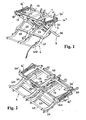
- The invention will be described in more detail on the basis of an embodiment, which is shown in the enclosed drawing, wherein
-
Fig. 1 is a perspective view of an apparatus for lifting and forwarding of logs during operation; -
Fig. 2 is a perspective view of an apparatus according toFig. 1 , in a collapsed state and ready for transporting thereof; -
Fig. 3 is a bottom view of the apparatus according toFig. 2 ; and -
Fig. 3 is a side view of the apparatus according toFig. 2 . - The apparatus generally consists of a bearing
frame 1, which is adapted for co-operation with twogroups legs fame 1 is arranged in a horizontal plane and extends essentially parallel to the ground and a desired distance there-from, preferably in appropriate working level of a machine or any other appliance, to which the logs need to be forwarded. Saidgroups legs pivot joints 23. - The
first group 2 consists of a desired number oflegs 20, which are preferably arranged parallel to each other and apart from each other, and thesecond group 3 oflegs 30 is arranged quite analogous. In this, pivotally interconnected and mutually co-operatinglegs common pivot joint 23. - When bearing in mind a desired rigidity and bearing capability of the apparatus as whole, said
legs 20 of thegroup 2 are preferably connected to each other by means of appropriate binding means 25, and thelegs 30 of thesecond group 3 are also connected to each other by means of appropriate binding means 35. - Said
first group 2 oflegs 20 further comprises a group 2' of levers 20', wherein each lever 20' is pivotably connected to each belongingleg 20 in the area of the end portion on the utmost distance from the ground. In common, even more than one lever 20' may be attached to each leg 20' or only to certain desired single legs 20'. - In addition, on the end portion, which is arranged at the largest distance from the ground, a
bearing frame 1 is pivotably connected to thesecond group 3 oflegs 30, and is simultaneously also pivotably connected with the group 2' of levers 20', which are connected with thefirst group 2 of thelegs 20. - Thanks to described concept, the apparatus is transformable from the state according to
Figs. 2 to 4 into the state according toFig. 1 and vice versa. Whenever available in the state according toFigs. 2 to 4 , the apparatus may be transported in a comfortable manner, while in the state according toFig. 1 the apparatus is stabilized on the ground, and at the same thebearing frame 1 is firmly maintained at a desired distance apart from the ground. - Said bearing
frame 1 is actually formed bylongitudinal beams rollers 13, which may be freely rotated aroundcorresponding axles 130. Furthermore, saidframe 1 is equipped with at least one forwarding means 14', 14" arranged at eachend section 10', 10" thereof. - Each forwarding means 14", 14" is driven by means of a hydraulic driving means 15, which is in this particular embodiment (
Fig. 3 ) a hydraulic motor, which is attached to one of saidlongitudinal beams frame 1 and moreover included into appropriate hydraulic circuit, which is hydraulically connected with corresponding driving unit of a tractor or a similar forestry working machine, which may enable both manipulating logs in forestry and also performing certain operations related to processing of wood, and in particularly transporting of apparatus according to the invention by means of appropriate trailer to each desired place. - In this particular embodiment each forwarding means 14', 14" is mounted within the bearing
frame 1 in such a manner, that it can be rotated around itsown axle 140, which quite analogous like by saidrollers 13 extends in a transversal direction of theframe 1, and moreover includes achain wheel 141', 141 ", which is via not shown chain connected with thechain wheel 151 of the hydraulic driving means 15. Said forwarding means 14', 14" may also be driven in any other manner, either by means of a direct co-operation of the driving means 15 with each corresponding forwarding means 14', 14", or also via an additional transmission unit, when desired or useful. - Still further, in this particular embodiment each forwarding means 14', 14" is available in form of a rotation-symmetric body having, the silhouette of which corresponds to a desired section of a truncated cone having a concave periphery surface or also to a desired section of a rotational hyperboloid or a similar solid, the silhouette of which at least approximately matches each potential silhouette of the logs, which should be put longitudinally onto the bearing
frame 1 of the apparatus. In this shown embodiment each forwarding means 14', 14" is realized in a pretty simple manner, namely in form of a welded structure, consisting of a group ofradial parts 144, which are equidistantly arranged in the circumferential direction, wherein each of them comprises a saw-like or toothed outwardly protrudingedge 142 and is moreover welded to a tubularcentral portion 143, which is moreover intended for appropriate attachment of the forwarding means 14', 14" to the bearingframe 1 or also for mounting of achain wheel 141', 141", when available. - In addition to said
groups legs frame 1 with includedrollers 13 and forwarding means 14', 14"; said apparatus also includes alifting unit 4, which consists of a group oflevers 41, which are each per se attached to saidlegs 20 of thefirst group 2, and for the purposes of achieving a desired rigidity mutually interconnected by means of a longitudinal binding means 45 in the area of theirend portions 410, which are preferably concave and herewith adapted for receipt of logs. Saidlifting unit 4 further includes appropriate transposingmeans 44, which is preferably a hydraulic cylinder, which is at the one hand connected to saidsecond group 3 oflegs 30, preferably to the longitudinal binding means 35 of thesecond group 3 oflegs 30, and on the other hand to at least onelever 41 of thelifting unit 4. Said transposingmeans 44 is attached to appropriate hydraulic circuit, which is hydraulically connected with a corresponding driving unit of a tractor or any other similar working machine, which may enable both manipulating logs in forestry and also performing certain operations related to processing of wood, and in particularly transporting of apparatus according to the invention by means of appropriate trailer to each desired place. - When the apparatus according to the invention is available in the state according to
Figs. 2 to 4 , bothgroups legs end portions 410 oflevers 41 are in contact with the ground, if the place of setting-up the apparatus is selected in a correct manner. As soon as the transposingmeans 44 is included into appropriate hydraulic circuit and a required pressure is established, saidend portions 410 of thelevers 41 are pressed towards the ground, upon which thesecond group 3 oflegs 30, to which thetransposing means 44 is connected, is pivoted in a direction apart from the ground. Saidsecond group 3 oflegs 30 consequently engages thefirst group 2 oflegs 20 as well as the bearingframe 1. As soon as the bearingframe 1 is transposed to a certain distance away from the ground i.e. approximately in a horizontal plane, thelegs groups means 44 said levers 20' first of all reach their vertical position, but are upon that still additionally pivoted behind/over their pivot joints on thebelonging legs 20 into their end position, in which any further movement in the sense of continuation of movement in the same direction is made impossible. Accordingly, the bearingframe 1 is on the one hand in the area of thelongitudinal beam 11 i.e. on the side of supporting thereof by means oflegs 20 of thefirst group 2 supported by means of said levers 20', which are even under certain additional loading securely prevented from any movement, and on the other hand in the area of the otherlongitudinal beam 12 by means oflegs 30, which are pressed towards the ground and extend crosswise with respect to the previously mentionedlegs 20 of thefirst group 2. When thelegs groups frame 1 is practically arrested between saidlegs lifting unit 4 is then pivoted away from the ground. Whenever saidlifting unit 4 is placed on the ground, a log can be simply and easily rolled thereon, namely on theend portions 410 of thelevers 41, and when theunit 4 is pivoted away from the ground, said log is lifted up to the level of the bearingframe 1 or even slightly higher, upon which the log is simply and easily rolled onto the bearingframe 1 and upon that transported by means of saidrollers 13 and forwarding means 14', 14"in each desired direction and with a desired velocity alongside the bearingframe 1. Whenever the operation of the apparatus needs to be terminated, the pressure within the hydraulic circuit is eliminated, upon which the levers 20' can be moved to the opposite side of the pivot joints i.e. in a direction towards the lifting unit, upon which the apparatus is collapsed into the state according toFigs 2 to 4 .
Claims (12)
- Apparatus for lifting and forwarding of logs, comprising- two groups (2, 3) of crosswise each to other arranged legs (20, 30), by which in each corresponding pivot joint (23) each leg (20) of the first group (2) is pivotably connected with the corresponding leg (30) of the second group (3), and where each of at least majority of legs (20) of the first group (2) is equipped with a lever (20'), which is pivotably attached thereto and arranged on those end portion thereof, which is faced away from the ground;
a bearing frame (1), which is at the one hand pivotably connected with the end portion of legs (30) of the second group(3), which is faced apart from the ground,
and on the other hand with said levers (20') on the legs (20) of the first group (2), wherein said frame (1) is furthermore equipped with transversally arranged rollers (13) as well as with at least one forwarding means (14', 14"); and
a lifting unit (4), which is pivotably attached to the first group (2) of legs (20) and supported by a hydraulic transposing means (44), which is attached to the second group (3) of legs (30). - Apparatus according to Claim 1, characterized in that the legs (20) of the first group (2) are firmly interconnected by means of a longitudinal binding means (25).
- Apparatus according to Claim 1 or 2, characterized in that the legs (30) of the second group (3) are firmly interconnected by means of a longitudinal binding means (35).
- Apparatus according to one of Claims 1 to 3, characterized in that the lifting unit (4) comprises a group of levers (41), where the end portions thereof are interconnected by means of a longitudinal binding means (45).
- Apparatus according to Claim 4, characterized in that the end portions (410) of the levers (41) of the lifting unit (4) are concave i.e. arched towards the ground.
- Apparatus according to one of the preceding Claims, characterized in that the hydraulic transposing means (44) is a hydraulic cylinder.
- Apparatus according to one of the preceding Claims, characterized in that the bearing frame (1) consists of two longitudinal beams (11, 12), between which a a group of freely around individual axles (130) rotated rollers (13) is foreseen, which extend transversally with respect to said beams (11, 12), as well as of at least one forwarding means (14', 14"), which is driven by means of adequate hydraulic driving means (15).
- Apparatus according to Claim 7, characterized in that two forwarding means (14', 14") are foreseen, where each of them is available on the belonging end portion (10', 10") of the bearing frame (1).
- Apparatus according to Claim 8, characterized in that each forwarding means (14', 14") comprises a chain wheel (142', 142") and is driven via appropriate chain by means of a hydraulic driving means (15), which is also equipped with a chain wheel (151).
- Apparatus according to Claim 8 or 9, characterized in that the forwarding means (14', 14") is conceived as a welded assembly, which consists of at least cylindrical central portion (143), to which then radial outwards extending parts (144) are firmly connected.
- Apparatus according to Claim 10, characterized in that the central portion (143) of each forwarding means (14', 14") is at least essentially tubular and that the radial parts (144) are arranged in a equidistant manner in the circular direction.
- Apparatus according to Claim 11, characterized in that each radial part (144) comprises a concave and toothed or saw-tooth articulated outward edge (142), which is therefore adapted for co-operation with the periphery of each log.
Applications Claiming Priority (2)
| Application Number | Priority Date | Filing Date | Title |
|---|---|---|---|
| SI200500162A SI22054A (en) | 2005-05-31 | 2005-05-31 | Device for lifting and passing of lumber |
| PCT/SI2006/000014 WO2007008179A1 (en) | 2005-05-31 | 2006-04-18 | Apparatus for lifting and forwarding of logs |
Publications (2)
| Publication Number | Publication Date |
|---|---|
| EP1885631A1 EP1885631A1 (en) | 2008-02-13 |
| EP1885631B1 true EP1885631B1 (en) | 2011-07-27 |
Family
ID=36659911
Family Applications (1)
| Application Number | Title | Priority Date | Filing Date |
|---|---|---|---|
| EP06733571A Expired - Lifetime EP1885631B1 (en) | 2005-05-31 | 2006-04-18 | Apparatus for lifting and forwarding of logs |
Country Status (4)
| Country | Link |
|---|---|
| EP (1) | EP1885631B1 (en) |
| AT (1) | ATE517830T1 (en) |
| SI (1) | SI22054A (en) |
| WO (1) | WO2007008179A1 (en) |
Cited By (2)
| Publication number | Priority date | Publication date | Assignee | Title |
|---|---|---|---|---|
| US11370147B2 (en) | 2017-04-18 | 2022-06-28 | Tajfun Planina Proizvodnja Strojev D.O.O. | Platform with an autonomous powering engine for mounting onto a firewood splitting apparatus |
| US11603298B2 (en) | 2017-05-15 | 2023-03-14 | Tajfun Planina Proizvodnja Strojev D.O.O. | Apparatus for hoisting and forwarding of logs |
Families Citing this family (2)
| Publication number | Priority date | Publication date | Assignee | Title |
|---|---|---|---|---|
| CN108002291A (en) * | 2017-12-01 | 2018-05-08 | 浙江理工大学 | The cabinet type cargo elevator of multi-angle |
| GB2590893A (en) * | 2019-11-01 | 2021-07-14 | Martin Andrew | A log lifter |
Family Cites Families (6)
| Publication number | Priority date | Publication date | Assignee | Title |
|---|---|---|---|---|
| BE546682A (en) * | ||||
| US475628A (en) * | 1892-05-24 | Portable log-carrier | ||
| CA900881A (en) * | 1970-06-10 | 1972-05-23 | Placements Jean Paul Tanguay Limitee | Conveyor |
| FR2461629A1 (en) * | 1979-07-20 | 1981-02-06 | Balency Briard | Steerable supply type trolley - has hydraulically lifted platform tilting to remain horizontal on stairways and slopes |
| CA2312104A1 (en) * | 1997-11-28 | 1999-06-10 | Stanley W. Redekop | High speed log ladder |
| DE20209407U1 (en) * | 2002-06-17 | 2003-07-31 | REMECH Systemtechnik GmbH & Co. KG, 07334 Kamsdorf | Lifting device, preferably for skid conveyors |
-
2005
- 2005-05-31 SI SI200500162A patent/SI22054A/en active Search and Examination
-
2006
- 2006-04-18 AT AT06733571T patent/ATE517830T1/en active
- 2006-04-18 EP EP06733571A patent/EP1885631B1/en not_active Expired - Lifetime
- 2006-04-18 WO PCT/SI2006/000014 patent/WO2007008179A1/en not_active Ceased
Cited By (2)
| Publication number | Priority date | Publication date | Assignee | Title |
|---|---|---|---|---|
| US11370147B2 (en) | 2017-04-18 | 2022-06-28 | Tajfun Planina Proizvodnja Strojev D.O.O. | Platform with an autonomous powering engine for mounting onto a firewood splitting apparatus |
| US11603298B2 (en) | 2017-05-15 | 2023-03-14 | Tajfun Planina Proizvodnja Strojev D.O.O. | Apparatus for hoisting and forwarding of logs |
Also Published As
| Publication number | Publication date |
|---|---|
| EP1885631A1 (en) | 2008-02-13 |
| ATE517830T1 (en) | 2011-08-15 |
| SI22054A (en) | 2006-12-31 |
| WO2007008179A1 (en) | 2007-01-18 |
Similar Documents
| Publication | Publication Date | Title |
|---|---|---|
| EP1885631B1 (en) | Apparatus for lifting and forwarding of logs | |
| DK161418B (en) | MACHINE FOR CUTTING THE GRAVES | |
| US4290733A (en) | Forage stack mover | |
| US3863848A (en) | Giant Tree Chopper | |
| US4440202A (en) | Tree delimber | |
| US3970125A (en) | Tree cutting apparatus | |
| US3832928A (en) | Portable pulpwood slashing machine | |
| US6962359B2 (en) | Arrangement for the suspension of wheels in a working machine | |
| WO2010002349A1 (en) | Loading system for forest machine | |
| US3866639A (en) | Tree trimming and transporting machine | |
| US3125234A (en) | gustine | |
| EP3216337A1 (en) | Equipment for shredding plant material | |
| US2621055A (en) | Adjustable vehicle carrier for portable sawmills or the like | |
| US6085811A (en) | Boom assembly and platform for tracked feller buncher machine | |
| FI67650C (en) | TRAEDAVKVISTNINGSANORDNING VID TRAEDAVVERKNINGSMASKIN | |
| US4344470A (en) | Delimbing apparatus | |
| US3020694A (en) | Tree clearing attachment for tractor | |
| FR2885484A1 (en) | AGRICULTURAL ENGINE COMPRISING A MOTOR VEHICLE AND SEVERAL WORK UNITS INTENDED TO CUT PLANT PRODUCTS | |
| US3580306A (en) | Mobile tree slasher | |
| EP3592687B1 (en) | Apparatus for hoisting and forwarding of logs | |
| EP0192330A1 (en) | Grass cutting attachment for tractor | |
| EP2825022B1 (en) | Mobile loading system for forest harvester | |
| FI112158B (en) | Movable working machine for terrain handling and transport of trees | |
| US936404A (en) | Cane-cutter. | |
| US20040244868A1 (en) | Forest machine |
Legal Events
| Date | Code | Title | Description |
|---|---|---|---|
| PUAI | Public reference made under article 153(3) epc to a published international application that has entered the european phase |
Free format text: ORIGINAL CODE: 0009012 |
|
| 17P | Request for examination filed |
Effective date: 20061206 |
|
| AK | Designated contracting states |
Kind code of ref document: A1 Designated state(s): AT BE BG CH CY CZ DE DK EE ES FI FR GB GR HU IE IS IT LI LT LU LV MC NL PL PT RO SE SI SK TR |
|
| DAX | Request for extension of the european patent (deleted) | ||
| GRAP | Despatch of communication of intention to grant a patent |
Free format text: ORIGINAL CODE: EPIDOSNIGR1 |
|
| GRAS | Grant fee paid |
Free format text: ORIGINAL CODE: EPIDOSNIGR3 |
|
| GRAA | (expected) grant |
Free format text: ORIGINAL CODE: 0009210 |
|
| AK | Designated contracting states |
Kind code of ref document: B1 Designated state(s): AT BE BG CH CY CZ DE DK EE ES FI FR GB GR HU IE IS IT LI LT LU LV MC NL PL PT RO SE SI SK TR |
|
| REG | Reference to a national code |
Ref country code: GB Ref legal event code: FG4D |
|
| REG | Reference to a national code |
Ref country code: CH Ref legal event code: EP |
|
| REG | Reference to a national code |
Ref country code: DE Ref legal event code: R096 Ref document number: 602006023333 Country of ref document: DE Effective date: 20110915 |
|
| REG | Reference to a national code |
Ref country code: SE Ref legal event code: TRGR |
|
| REG | Reference to a national code |
Ref country code: NL Ref legal event code: VDEP Effective date: 20110727 |
|
| PG25 | Lapsed in a contracting state [announced via postgrant information from national office to epo] |
Ref country code: LT Free format text: LAPSE BECAUSE OF FAILURE TO SUBMIT A TRANSLATION OF THE DESCRIPTION OR TO PAY THE FEE WITHIN THE PRESCRIBED TIME-LIMIT Effective date: 20110727 Ref country code: BE Free format text: LAPSE BECAUSE OF FAILURE TO SUBMIT A TRANSLATION OF THE DESCRIPTION OR TO PAY THE FEE WITHIN THE PRESCRIBED TIME-LIMIT Effective date: 20110727 Ref country code: PT Free format text: LAPSE BECAUSE OF FAILURE TO SUBMIT A TRANSLATION OF THE DESCRIPTION OR TO PAY THE FEE WITHIN THE PRESCRIBED TIME-LIMIT Effective date: 20111128 Ref country code: FI Free format text: LAPSE BECAUSE OF FAILURE TO SUBMIT A TRANSLATION OF THE DESCRIPTION OR TO PAY THE FEE WITHIN THE PRESCRIBED TIME-LIMIT Effective date: 20110727 Ref country code: NL Free format text: LAPSE BECAUSE OF FAILURE TO SUBMIT A TRANSLATION OF THE DESCRIPTION OR TO PAY THE FEE WITHIN THE PRESCRIBED TIME-LIMIT Effective date: 20110727 Ref country code: IS Free format text: LAPSE BECAUSE OF FAILURE TO SUBMIT A TRANSLATION OF THE DESCRIPTION OR TO PAY THE FEE WITHIN THE PRESCRIBED TIME-LIMIT Effective date: 20111127 |
|
| PG25 | Lapsed in a contracting state [announced via postgrant information from national office to epo] |
Ref country code: CY Free format text: LAPSE BECAUSE OF FAILURE TO SUBMIT A TRANSLATION OF THE DESCRIPTION OR TO PAY THE FEE WITHIN THE PRESCRIBED TIME-LIMIT Effective date: 20110727 Ref country code: GR Free format text: LAPSE BECAUSE OF FAILURE TO SUBMIT A TRANSLATION OF THE DESCRIPTION OR TO PAY THE FEE WITHIN THE PRESCRIBED TIME-LIMIT Effective date: 20111028 Ref country code: LV Free format text: LAPSE BECAUSE OF FAILURE TO SUBMIT A TRANSLATION OF THE DESCRIPTION OR TO PAY THE FEE WITHIN THE PRESCRIBED TIME-LIMIT Effective date: 20110727 Ref country code: SI Free format text: LAPSE BECAUSE OF FAILURE TO SUBMIT A TRANSLATION OF THE DESCRIPTION OR TO PAY THE FEE WITHIN THE PRESCRIBED TIME-LIMIT Effective date: 20110727 Ref country code: PL Free format text: LAPSE BECAUSE OF FAILURE TO SUBMIT A TRANSLATION OF THE DESCRIPTION OR TO PAY THE FEE WITHIN THE PRESCRIBED TIME-LIMIT Effective date: 20110727 |
|
| PG25 | Lapsed in a contracting state [announced via postgrant information from national office to epo] |
Ref country code: CZ Free format text: LAPSE BECAUSE OF FAILURE TO SUBMIT A TRANSLATION OF THE DESCRIPTION OR TO PAY THE FEE WITHIN THE PRESCRIBED TIME-LIMIT Effective date: 20110727 Ref country code: SK Free format text: LAPSE BECAUSE OF FAILURE TO SUBMIT A TRANSLATION OF THE DESCRIPTION OR TO PAY THE FEE WITHIN THE PRESCRIBED TIME-LIMIT Effective date: 20110727 |
|
| PG25 | Lapsed in a contracting state [announced via postgrant information from national office to epo] |
Ref country code: EE Free format text: LAPSE BECAUSE OF FAILURE TO SUBMIT A TRANSLATION OF THE DESCRIPTION OR TO PAY THE FEE WITHIN THE PRESCRIBED TIME-LIMIT Effective date: 20110727 Ref country code: RO Free format text: LAPSE BECAUSE OF FAILURE TO SUBMIT A TRANSLATION OF THE DESCRIPTION OR TO PAY THE FEE WITHIN THE PRESCRIBED TIME-LIMIT Effective date: 20110727 Ref country code: IT Free format text: LAPSE BECAUSE OF FAILURE TO SUBMIT A TRANSLATION OF THE DESCRIPTION OR TO PAY THE FEE WITHIN THE PRESCRIBED TIME-LIMIT Effective date: 20110727 |
|
| PLBE | No opposition filed within time limit |
Free format text: ORIGINAL CODE: 0009261 |
|
| STAA | Information on the status of an ep patent application or granted ep patent |
Free format text: STATUS: NO OPPOSITION FILED WITHIN TIME LIMIT |
|
| PG25 | Lapsed in a contracting state [announced via postgrant information from national office to epo] |
Ref country code: DK Free format text: LAPSE BECAUSE OF FAILURE TO SUBMIT A TRANSLATION OF THE DESCRIPTION OR TO PAY THE FEE WITHIN THE PRESCRIBED TIME-LIMIT Effective date: 20110727 |
|
| 26N | No opposition filed |
Effective date: 20120502 |
|
| REG | Reference to a national code |
Ref country code: DE Ref legal event code: R097 Ref document number: 602006023333 Country of ref document: DE Effective date: 20120502 |
|
| PG25 | Lapsed in a contracting state [announced via postgrant information from national office to epo] |
Ref country code: MC Free format text: LAPSE BECAUSE OF NON-PAYMENT OF DUE FEES Effective date: 20120430 |
|
| REG | Reference to a national code |
Ref country code: CH Ref legal event code: PL |
|
| GBPC | Gb: european patent ceased through non-payment of renewal fee |
Effective date: 20120418 |
|
| REG | Reference to a national code |
Ref country code: IE Ref legal event code: MM4A |
|
| PG25 | Lapsed in a contracting state [announced via postgrant information from national office to epo] |
Ref country code: IE Free format text: LAPSE BECAUSE OF NON-PAYMENT OF DUE FEES Effective date: 20120418 Ref country code: LI Free format text: LAPSE BECAUSE OF NON-PAYMENT OF DUE FEES Effective date: 20120430 Ref country code: GB Free format text: LAPSE BECAUSE OF NON-PAYMENT OF DUE FEES Effective date: 20120418 Ref country code: CH Free format text: LAPSE BECAUSE OF NON-PAYMENT OF DUE FEES Effective date: 20120430 |
|
| PG25 | Lapsed in a contracting state [announced via postgrant information from national office to epo] |
Ref country code: BG Free format text: LAPSE BECAUSE OF FAILURE TO SUBMIT A TRANSLATION OF THE DESCRIPTION OR TO PAY THE FEE WITHIN THE PRESCRIBED TIME-LIMIT Effective date: 20111027 |
|
| PG25 | Lapsed in a contracting state [announced via postgrant information from national office to epo] |
Ref country code: ES Free format text: LAPSE BECAUSE OF FAILURE TO SUBMIT A TRANSLATION OF THE DESCRIPTION OR TO PAY THE FEE WITHIN THE PRESCRIBED TIME-LIMIT Effective date: 20111107 |
|
| PG25 | Lapsed in a contracting state [announced via postgrant information from national office to epo] |
Ref country code: TR Free format text: LAPSE BECAUSE OF FAILURE TO SUBMIT A TRANSLATION OF THE DESCRIPTION OR TO PAY THE FEE WITHIN THE PRESCRIBED TIME-LIMIT Effective date: 20110727 |
|
| PG25 | Lapsed in a contracting state [announced via postgrant information from national office to epo] |
Ref country code: LU Free format text: LAPSE BECAUSE OF NON-PAYMENT OF DUE FEES Effective date: 20120418 |
|
| PG25 | Lapsed in a contracting state [announced via postgrant information from national office to epo] |
Ref country code: HU Free format text: LAPSE BECAUSE OF FAILURE TO SUBMIT A TRANSLATION OF THE DESCRIPTION OR TO PAY THE FEE WITHIN THE PRESCRIBED TIME-LIMIT Effective date: 20060418 |
|
| PGFP | Annual fee paid to national office [announced via postgrant information from national office to epo] |
Ref country code: SE Payment date: 20140422 Year of fee payment: 9 |
|
| REG | Reference to a national code |
Ref country code: SE Ref legal event code: EUG |
|
| PG25 | Lapsed in a contracting state [announced via postgrant information from national office to epo] |
Ref country code: SE Free format text: LAPSE BECAUSE OF NON-PAYMENT OF DUE FEES Effective date: 20150419 |
|
| REG | Reference to a national code |
Ref country code: FR Ref legal event code: PLFP Year of fee payment: 11 |
|
| REG | Reference to a national code |
Ref country code: FR Ref legal event code: PLFP Year of fee payment: 12 |
|
| REG | Reference to a national code |
Ref country code: FR Ref legal event code: PLFP Year of fee payment: 13 |
|
| PGFP | Annual fee paid to national office [announced via postgrant information from national office to epo] |
Ref country code: FR Payment date: 20250324 Year of fee payment: 20 |
|
| PGFP | Annual fee paid to national office [announced via postgrant information from national office to epo] |
Ref country code: DE Payment date: 20250324 Year of fee payment: 20 |
|
| PGFP | Annual fee paid to national office [announced via postgrant information from national office to epo] |
Ref country code: AT Payment date: 20250325 Year of fee payment: 20 |
|
| REG | Reference to a national code |
Ref country code: DE Ref legal event code: R071 Ref document number: 602006023333 Country of ref document: DE |