EP1885054B1 - Verfahren zur Zustandsschätzung eines Systems und eine zugehörige Vorrichtung zur Ermittlung der Position und der Drehzahl eines bürstenlosen Motors - Google Patents
Verfahren zur Zustandsschätzung eines Systems und eine zugehörige Vorrichtung zur Ermittlung der Position und der Drehzahl eines bürstenlosen Motors Download PDFInfo
- Publication number
- EP1885054B1 EP1885054B1 EP06425561A EP06425561A EP1885054B1 EP 1885054 B1 EP1885054 B1 EP 1885054B1 EP 06425561 A EP06425561 A EP 06425561A EP 06425561 A EP06425561 A EP 06425561A EP 1885054 B1 EP1885054 B1 EP 1885054B1
- Authority
- EP
- European Patent Office
- Prior art keywords
- ref
- motor
- function
- state
- rotor
- Prior art date
- Legal status (The legal status is an assumption and is not a legal conclusion. Google has not performed a legal analysis and makes no representation as to the accuracy of the status listed.)
- Expired - Fee Related
Links
Images
Classifications
-
- G—PHYSICS
- G05—CONTROLLING; REGULATING
- G05B—CONTROL OR REGULATING SYSTEMS IN GENERAL; FUNCTIONAL ELEMENTS OF SUCH SYSTEMS; MONITORING OR TESTING ARRANGEMENTS FOR SUCH SYSTEMS OR ELEMENTS
- G05B13/00—Adaptive control systems, i.e. systems automatically adjusting themselves to have a performance which is optimum according to some preassigned criterion
- G05B13/02—Adaptive control systems, i.e. systems automatically adjusting themselves to have a performance which is optimum according to some preassigned criterion electric
- G05B13/04—Adaptive control systems, i.e. systems automatically adjusting themselves to have a performance which is optimum according to some preassigned criterion electric involving the use of models or simulators
-
- H—ELECTRICITY
- H02—GENERATION; CONVERSION OR DISTRIBUTION OF ELECTRIC POWER
- H02P—CONTROL OR REGULATION OF ELECTRIC MOTORS, ELECTRIC GENERATORS OR DYNAMO-ELECTRIC CONVERTERS; CONTROLLING TRANSFORMERS, REACTORS OR CHOKE COILS
- H02P21/00—Arrangements or methods for the control of electric machines by vector control, e.g. by control of field orientation
- H02P21/13—Observer control, e.g. using Luenberger observers or Kalman filters
-
- H—ELECTRICITY
- H02—GENERATION; CONVERSION OR DISTRIBUTION OF ELECTRIC POWER
- H02P—CONTROL OR REGULATION OF ELECTRIC MOTORS, ELECTRIC GENERATORS OR DYNAMO-ELECTRIC CONVERTERS; CONTROLLING TRANSFORMERS, REACTORS OR CHOKE COILS
- H02P21/00—Arrangements or methods for the control of electric machines by vector control, e.g. by control of field orientation
- H02P21/14—Estimation or adaptation of machine parameters, e.g. flux, current or voltage
- H02P21/18—Estimation of position or speed
-
- H—ELECTRICITY
- H02—GENERATION; CONVERSION OR DISTRIBUTION OF ELECTRIC POWER
- H02P—CONTROL OR REGULATION OF ELECTRIC MOTORS, ELECTRIC GENERATORS OR DYNAMO-ELECTRIC CONVERTERS; CONTROLLING TRANSFORMERS, REACTORS OR CHOKE COILS
- H02P21/00—Arrangements or methods for the control of electric machines by vector control, e.g. by control of field orientation
- H02P21/24—Vector control not involving the use of rotor position or rotor speed sensors
Definitions
- This invention relates the techniques for estimating the evolution of a system and more particularly to a method for estimating the state of a system.
- the method of this invention may be used for estimating position and speed of a brushless motor without employing speed and position sensors and may be implemented in a hardware form.
- the invention further relates to a device for generating estimation signals of position and speed of the rotor of a brushless motor, to a feedback control device of a brushless motor and to a power steering system that implement the method of this invention.
- Electric motors are used in the automotive field not only in electrically powered cars but also as actuators in servo-systems for driving pumps, compressors and the like.
- Permanent magnet brushless motors are often preferred in these automotive applications.
- the characteristics of permanent magnet brushless motors are particularly suitable for automotive applications: they are relatively lightweight, have a high power density, a small size and are very reliable, though they are relatively expensive (due to the costs of the magnets used for fabricating the rotor), more difficult to control than a traditional DC electrical machine, and require more or less precise angular position sensors (depending on the brushless motor and the control strategy).
- a second angular position sensor is commonly installed for controlling that the first sensor be working correctly.
- a sensorless estimation algorithm could compensate errors due to aging or to alterations of the main sensor, making superfluous the second sensor and thus solving the drawback of its encumbrance.
- estimators of the angular position of the rotor of a permanent magnet brushless machine may be found in literature [4].
- one of the most used techniques is based on the so-called "state observers" for monitoring the state of the system. In this case it is necessary to know at least roughly a mathematical model of the electric machine.
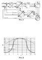
- Figure 1 illustrates the block diagram of a typical field oriented control of a permanent magnet brushless machine (BLDC).
- the feedback signals, I sd (direct current) and I sq (quadrature current), that the PI controllers compare with the reference currents I sd ref and I sq ref , are obtained with a double transform of the phase currents of the motor I U , I V and I W .
- the dynamics of the brushless motor may be studied both in the system of coordinates (d,q) as well as in the system ( ⁇ , ⁇ ).
- z p indicates the number of polar pairs
- c M the constant of the electric machine (that is the ratio between the generated torque and the current I sq circulating when the rotor is blocked)
- the values of state variables of the brushless motor that in equation (5) are the current I sq and the speed ⁇ , may be estimated with the so-called “state estimators”, that are algorithms for calculating the values of state variables of a system, if a mathematical model thereof defined in function of the detected inputs and outputs variables is known.
- a state observer that is largely used for controlling brushless motors is the so-called Luenberg state observer [4].
- the optimal state observer is the Kalman filter.
- the gain of the filter is calculated considering also the statistical properties of the noise of the process (uncertainty relative to the knowledge of the dynamics of the system) and of the measurement error.
- the extended Kalman filter (EKF) is an improvement of the Kalman filter suitable for systems having a nonlinear dynamics and may be used for estimating speed and position of the rotor. Therefore, it is possible to use equations (4) as a mathematical model of the brushless motor.
- the system of nonlinear equations is linearized and discretized around sampling instants taken at constant intervals, thus the standard Kalman filter is applied to the linearized system of discrete-time equations.
- k) of the system at the step k +1 is a function of the a priori estimation x(k
- k ⁇ f x ⁇ k
- k ⁇ x ⁇ ⁇ k
- the values of the matrix of gains K(k) are adjusted such that the estimated values of the outputs g(x ⁇ (k
- the EKF may be used when the covariance matrices of the process noise Q and of the measurement noise R are known. If these matrices are known, it is possible to calculate at each step the gain of the EKF and thus to estimate the state of the system.
- different model-based approaches are compared for estimating the angular position of the rotor of a permanent magnet brushless machine, a Luenberger state observer, a reduced Luenberger state observer, an EKF and so on. The best performances in terms of accuracy in tracking the kinematics of the rotor are provided by the EKF.
- the computational loads that is scalar multiplications, integrations, trigonometric functions
- 0) are estimated during an off-line training phase by means of an evolutionary algorithm for minimizing a pre-established cost function defined in function of the estimated outputs of the system, of the detected outputs, of the estimated values of at least a state of the system and of the corresponding detected values in response to a pre-established input pattern. This allows even to obtain accurate estimations of data of state of a system without knowing all initial conditions.
- the cost function is the mean square error of the difference between the estimated and the measured outputs and between the estimated values of at least a state variable of the system and the corresponding detected values, in response to a pre-established input pattern.
- 0) are known and it is possible to estimate data of state starting from the inputs and the outputs of the system.
- the just described technique to a brushless motor, it is possible to estimate position and speed of the rotor of the motor without installing dedicated sensors thereon, but simply by detecting the currents that flows through the windings (that are the outputs of the brushless motor) and the driving voltages of the motor (that are the inputs of the motor).
- the method of this invention for estimating position and speed of a brushless motor may be implemented in a relative device.
- a device may be used for controlling a brushless motor, or it may be introduced in the control loop of a brushless motor of a power steering system, in order to make the driver feel an antagonist torque on the steering wheel determined, according to a pre-established waveform, in function of the speed of the vehicle and of the steering angle.
- the methods of this invention may even be implemented via software by a program executed by a computer or a microprocessor.
- This invention discloses a method based on a so-called free-derivative state observer for estimating data of state variables of a system that may be used, in particular, for estimating, in a sensorless fashion, speed and position of the rotor of a brushless motor without installing dedicated sensors.
- the method of this invention is advantageous both from the point of view of the computational load required for its implementation and from the point of view of the rapidity of its response and the accuracy of its estimations.
- the method of this invention uses a soft computing procedure based on the use of evolutionary algorithms.
- the method has been tested on an EPS application (Electric Power Steering), that is on specific application patterns of an EPS system wherein the brushless motor is used for providing a torque for helping the driver while steering.
- EPS application Electric Power Steering
- f x f x ⁇ + f ⁇ ⁇ x ⁇ ⁇ x - x ⁇ + f 2 x ⁇ 2 ⁇ x - x ⁇ 2 + f 3 x ⁇ 6 ⁇ x - x ⁇ 3 + ...
- f DD ⁇ x ⁇ f ⁇ x ⁇ + h - f ⁇ x ⁇ - h 2 ⁇ h
- f DD ⁇ x ⁇ f ⁇ x ⁇ + h + f ⁇ x ⁇ - h - 2 ⁇ f x ⁇ h 2
- Equation (14) may be interpreted as a Taylor approximation in which the derivatives are substituted by central finite differences such as equations (15). In order to evaluate the accuracy of the approximation it is sufficient to substitute in equation (14) the Taylor series expansion (equation (11)) in place of f ( x ⁇ + h ) and f ( x ⁇ - h ).
- f x ⁇ + f DD ⁇ x ⁇ ⁇ x - x ⁇ + f DD ⁇ x ⁇ 2 ⁇ x - x ⁇ 2 f x ⁇ + f ⁇ ⁇ x ⁇ ⁇ x - x ⁇ + f ⁇ ⁇ x ⁇ 2 ⁇ x - x ⁇ 2 + f 3 x ⁇ ⁇ h 2 2 ⁇ 3 + f 5 x ⁇ ⁇ h 4 2 ⁇ 3 ⁇ 4 ⁇ 5 + ... ⁇ x - x ⁇ + f 4 x ⁇ ⁇ h 2 2 ⁇ 3 ⁇ 4 + f 6 x ⁇ ⁇ h 4 2 ⁇ 3 ⁇ 4 ⁇ 5 ⁇ 6 + ... ⁇ x - x ⁇ 2
- Figure 2 compares the polynomial approximation to the second order of a function f in the neighborhood of a point x ⁇ carried out respectively with the Stirling approximation formula and the Taylor series expansion. It is possible to infer that the approximation obtained with the Taylor series expansion worsen significantly the more we get far from point x ⁇ .
- the Stirling interpolation formula of the second order, with the parameter h equal to 3.5 fairly approximates the function even relatively far from the point of interest.
- ⁇ p and ⁇ p represent the average and difference operators, respectively.
- EKF is one of the most known state observers used for tracking the functioning state of a nonlinear system. It is based on the Taylor series approximation formula, that depends only upon the current estimation of the state variables of the system and not upon the uncertainty/variance associated to this estimation.
- DD1 and DD2 filters are among the most known state observer, they are used for tracking nonlinear systems and they are based on the Stirling approximation formula. These filters are based to the first and second order approximations, respectively, described by equations (27), (29), (31) and (32).
- the filter to be used is a DD1 filter, but the same considerations apply, mutatis mutandis, also if a filter DD2 or any other filter based on the Stirling approximation formula of any order, even larger than the second order, is used.
- f represent the nonlinear function that ties the state variables of the system, the inputs and the process noise at step k -th to the a priori estimation of the state variables at step ( k +1)-th.
- This difficulty is overcome, according to an aspect of this invention, by carrying out a preliminary off-line tuning.
- This preliminary operation is carried out by driving the system according to a pre-established input pattern, sensing the values of output variables and of at least a state variable instant by instant through sensors and updating the covariance matrices of the measurement noise and the process noise and the initial values of the covariance matrix of the state with and evolutionary algorithm such to minimize a pre-established cost function.
- this cost function is the root mean square of the difference between the estimated values and the respective sensed values.
- the state observer is trained for estimating data of state variables of the system without using the sensor of the state variable.
- a state observer may be used in particular (but not only) for controlling a brushless motor without using any position and/or speed sensor.
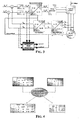
- FIG. 3 depicts the block diagram of a state observer of this invention OPTIMIZED STATE OBSERVER for controlling in a field oriented mode the brushless motor BLDC motor.
- the inputs of the state observer of this invention are the voltages U sq ref and U sd ref generated by the controllers PI that implement a proportional-integral function, that control the electric machine through the PWM stage and the currents I sq and I sd in the rotoric reference system.
- the values of these currents are obtained by measuring the currents I U , I V and I W and by applying the above mentioned Clarke and Park transforms.
- a characteristic of the state observer of this invention consists in that it is capable of estimating speed and position of a brushless motor without using a dedicated sensor (such as resolvers, Hall sensors, encoders and the like).
- the estimation of the rotor position is used for carrying out the direct and inverse Park transforms.
- the initial values of the covariance matrix of the state variables and the covariance matrices associated to the process noise and measurement noise are determined in an off-line tuning phase.
- Figure 4 shows how the initial value of the covariance matrix of the state variables and how the covariance matrix relative to the process noise are adjusted because of the automatic tuning guided by evolutionary algorithms.
- the state observer of this invention may be used for estimating position and speed of the rotor of a brushless motor even without knowing the initial position of the rotor, but by knowing exclusively its initial speed. This is not a limitation when the initial speed is known (e. g. it is null), for example it the control of the motor starts when it is still.
- a column type EPS system [1] and [2] has been considered.
- the brushless motor contained therein is connected to the steering column through torque reducers.
- Figure 5 describes the experimental set-up of the EPS system in HILS configuration (Hardware-In-the-Loop Simulation).
- a further brushless motor is used for providing to the rack-pinion system different profiles of load torques.
- both brushless motors the motor that powers the steering by supplying a supplementary steering torque through the torque reduction gears and the motor that supplies an antagonist torque to the rack-pinion system, are controlled by a PC.
- the torque and the steering angle are measured by a torque sensor mounted on the top of the steering column.
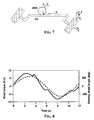
- Figure 8 depicts the sensor.
- the sensor is a torsion bar in which two optical encoders measure respectively the angular position of the steering-wheel ⁇ SW (steering angle) and the angular position ⁇ SS in respect to the steering column (that is the angular position in respect to the steering shaft).
- the described EPS system in Figures 5 and 6 may be subdivided into two parts, a steering column and an assisting electric motor.
- T s , T l , T m be the steering torque, the load torque transmitted from the rack-pinion system to the steering column and the torque generated by the assisting electric motor, respectively.
- the load torque T l it takes into account the friction between the wheels and the road and the efficiency of the mechanic gears for transmitting torques (rack-pinion, steering shaft and the like).
- J m ⁇ ⁇ ⁇ m + b M ⁇ ⁇ ⁇ m T m - T l N
- J m and b M are the inertia momentum and the dampening coefficient of the electric motor
- N is the ratio reduction/transmission relative to the reduction gear that couples the assisting electric motor to the steering column.
- the equations used for describing the functioning of the brushless motor of this application are equations (4).
- the factor n considers how, in function of the geometric-mechanical characteristics of the EPS system, the steering angle ⁇ SW imposed by the driver is transmitted to the wheels.
- T road The antagonist torque T road due to the coupling of the wheels with the road is simply obtained by the vector product of the force F R to which the rack is subjected during the motion of the vehicle and the radius r of the pinion:
- Figure 8 depicts the graph of the load torque due to friction between the road and the wheels of the vehicle for certain established values of the slipping angle and of the slipping ratio ( s, ⁇ ) .
- an EPS system The main functions of an EPS system are the reduction of the steering torque and the improvement of the return of the steering wheel to its start position after a cornering (a displacement describing a J).
- a cornering a displacement describing a J
- an assisting torque is initially provided to the steering column for reducing the torque that a driver feels while steering.
- the EPS system rotates the steering-wheel to its initial position without oscillations and overshoots, that otherwise would be present if the power steering system was not present.
- time intervals in which the control logic circuitry of the EPS is enabled for reducing the steering torque and for rotating the steering wheel in its initial position are distinct.
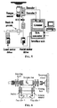
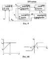
- Figure 9 depicts a block diagram of the control logic for reducing the steering torque in an EPS system.
- the idea of this control consists in encoding in the block TORQUE MAP the driving style of a driver, that is a function of the speed V of the vehicle and of the steering angle ⁇ SW established by the driver.
- the objective of the control is to make that the torque felt by the driver while steering, that is T S , be as close as possible to the reference torque, that is T rs , stored in the look-up table of the block TORQUE MAP.
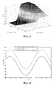
- the function that gives the steering torque upon the vehicle speed and the steering angle ⁇ SW may be illustrated as follows:
- FIG 10 the graphs of the reference steering torque in function of the speed of the vehicle and of the steering angle are depicted.
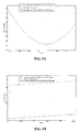
- a sample 3-D representation of a look-up table of the reference steering torques is depicted in Figure 11 .
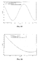
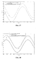
- Figures 12 , 13 , 14 , 15, 16 illustrate the results of a simulation of the EPS system in which the kinematics (position and speed) of the rotor of the brushless motor has been estimated on a test pattern by means of the method of this invention and compared with that measured through dedicated sensors.
- Figure 14 is a detail view of the graph of Figure 12 . It is evident how fast the values estimated with the method of this invention are corrected for tracking the waveform that describes the measured position of the rotor by a dedicated sensor.
- the method of this invention is effective even when both speed and initial position of the rotor are unknown.
- Figure 18 depicts the result of a simulation in which also the initial speed of the rotor has been supposed unknown. This situation could occur for example in an EPS application when, because of the fact that the vehicle is running fast in a highway, the electric motor is disabled, or in an e-brake application when, because of an abrupt brake after having brought a piston in its rest position, the rotor of an electric motor is disconnected from the servo-system that couples it to the piston. In both cases, the method of this invention is capable of resuming in a short time an efficient tracking of the kinematics of the rotor even using an inaccurate determination of the initial conditions.
- parameters of the filter DD1 are optimized through evolutionary (genetic) algorithms, such as the PSOA (Particle Swarm Optimization Algorithm) or ES (Evolution Strategies).
- the optimized tuning procedure of this invention not only simplifies the set-up phase of the considered model of the state observer but, which is of paramount importance, allows to enhance the tracking performances.
- Figure 18 shows the results that have been obtained, after having spent a very long time for searching the optimal values of parameters of the filter in the estimation of the angular position of the rotor of the brushless machine on the same specific patterns of the same application considered in Figures 12 , 13 and 14 .
- an optimized tuning of the parameters of the filter it is possible to compensate immediately the fact that the initial angular position of the rotor is unknown and it is possible to have a negligible error in steady-state conditions.
- the method for estimating data of state variables can be used for tracking the kinematics of the rotor of a brushless motor.
- a device of this invention for estimating speed and position of a rotor of a motor could replace a dedicated sensor used for monitoring the rotor position.
- the method of this invention could be used in a diagnostic device for sensing, possibly in advance, abnormal functioning of certain parts of the system, such as for example possible faults of sensors, of actuators, or even variations of intrinsic structural parameters of the system. Depending on the cases, these faults could be simply diagnosed for signaling the driver that parts/subsystems of the vehicle need to be checked, or could be balanced/compensated by adjusting internal parameters of the control system.
Claims (11)
- Verfahren zum Schätzen von Daten von Zustandsvariablen eines Systems, wodurch ein mathematisches Eingang-Zustand-Ausgang-Modell des Systems bekannt ist, das die folgenden Schritte aufweist:Installieren einer Schaltung zum Schätzen von Daten von Zustandsvariablen des Systems, das mindestens einen Filter aufweist, der eine Schätzung gemäß einer Stirling-Näherungsformel irgendeiner Ordnung als Funktion von Eingangsdaten, Ausgangsdaten des Systems und von Parametern der Filter ausführt, die Werte von Komponenten von Kovarianzmatrizen von Prozeßstörungen und von Meßstörungen des Systems repräsentieren;Trainieren der Schätzvorrichtung, indem offline die Schritte ausgeführt werden:Versorgen des Systems mit im voraus festgelegten Eingangsmustern und Ermitteln entsprechender Ausgangsdaten und eines Datenwerts mindestens einer Zustandsvariablen des Systems,Schätzen des Datenwerts der mindestens einen Zustandsvariablen des Systems für die im voraus festgelegten Eingangsmuster,Einstellen der Parameter des Filters mit einem evolutionären Algorithmus, um eine im voraus festgelegte Kostenfunktion zu minimieren, die als Funktion der geschätzten Ausgangsdaten des Systems, der abgetasteten Ausgangsdaten, des mindestens einen geschätzten Zustandsdatenwerts des Systems und des entsprechenden abgetasteten Zustandsdatenwerts definiert ist;Schätzen der Zustandsdaten des Systems während des normalen Funktionierens unter Verwendung der offline trainierten Schätzvorrichtung.
- Verfahren nach Anspruch 1, wobei die im voraus festgelegte Kostenfunktion der Effektivwert der Differenz zwischen den geschätzten Ausgangsdaten des Systems und den abgetasteten Ausgangsdaten und zwischen dem mindestens einen geschätzten Zustandsdatenwert des Systems und dem entsprechenden abgetasteten Zustandsdatenwert ist.
- Verfahren nach Anspruch 1, wobei der evolutionäre Algorithmus ein PSOA oder ein ES ist.
- Verfahren nach Anspruch 1, wobei der Filter ein DD1- oder ein DD2-Filter ist.
- Verfahren zum Schätzen der Position und der Drehzahl des Rotors eines bürstenlosen Motors, der in einer Rückkopplungsschleife gesteuert wird, die umfaßt: Schaltungsmittel zum Erzeugen von Rückkopplungssignalen, die die Ströme (Isq, Isd ) die im Motor bezüglich eines Rotorbezugssystems fließen, als Funktion der Ströme repräsentieren, die in den Wicklungen des Motors abgetastet werden, eine Steuereinrichtung, in die die repräsentativen Signale


 - Abtasten der Steuerspannungen
 - Berechnen von Werten der Ströme (Isq, Isd ) die im Motor bezüglich des Rotorbezugssystems als Funktion der geschätzten Position des Rotors in der gegenwärtigen PWM-Periode fließen;- Schätzen der Werte der Position und der Drehzahl des Rotors in der nächsten PWM-Periode durch das Verfahren nach Anspruch 1 als Funktion der Abtastwerte der Steuerspannungen
- Verfahren nach Anspruch 5, wobei die Werte der Ströme (Isq, Isd ) die im Motor bezüglich des Rotorbezugssystems fließen, aus abgetasteten Abtastwerten des Stroms erhalten werden, der durch die Wicklungen des Motors fließt, indem eine Clarke-Transformation gefolgt von einer Park-Transformation ausgeführt werden, die als Funktion der geschätzten Position des Rotors in der gegenwärtigen PWM-Periode definiert ist.
- Vorrichtung zum Erzeugen von Signalen, die für die Drehzahl und die Position des Rotors eines bürstenlosen Motors repräsentativ sind, der in einer Rückkopplungsschleife gesteuert wird, die umfaßt: Schaltungsmittel, die eingerichtet sind, Rückkopplungssignale zu erzeugen, die die Ströme (Isq, Isd ) die im Motor bezüglich eines Rotorbezugssystems fließen, als Funktion der Ströme repräsentieren, die in den Wicklungen des Motors abgetastet werden, eine Steuereinrichtung, in die die repräsentativen Signale


- Vorrichtung zur Rückkopplungssteuerung eines bürstenlosen Motors, die aufweist:Schaltungsmittel, die eingerichtet sind, Rückkopplungssignale zu erzeugen, die die Ströme (Isq, Isd ), die im Motor fließen, in Bezug auf ein Rotorbezugssystem als Funktion der Ströme, die in den Wicklungen des Motors abgetastet werden und als Funktion der Position des Rotors in der gegenwärtigen PWM repräsentieren;eine Steuereinrichtung, in die die repräsentativen Signale


 eine Vorrichtung nach Anspruch 6, die eingerichtet ist, Signale zu erzeugen, die die Drehzahl und die Position des Rotors in einer nachfolgenden PWM-Periode repräsentieren.
 - Servolenkungssystem, das eingerichtet ist, ein Hilfslenkungsdrehmoment (Ta) während des Lenkens zu erzeugen, das aufweist:einen bürstenlosen Motor, der eingerichtet ist, das Hilfsdrehmoment (Ta) als Funktion von Steuersignalen zu erzeugen, die darin eingegeben werden;einen Sensor, der eingerichtet ist, ein Signal zu erzeugen, das ein Gesamtdrehmoment (Ts) repräsentiert, das ein Fahrer ausgleichen muß;einen Steuerschaltungskomplex des Motors, der aufweist:die Vorrichtung nach Anspruch 8, die eingerichtet ist, den Motor als Funktion von Bezugssignalen
 Schaltungsmittel, die eingerichtet sind, die Bezugssignale
- Servolenkungssystem nach Anspruch 9, das ferner Schaltungsmittel aufweist, die eingerichtet sind, den Bezugswert (Trs) als Funktion der Geschwindigkeit des Fahrzeugs, in das das Servolenkungssystem eingebaut ist, und des Lenkwinkels des Fahrzeugs festzulegen.
- Programm für einen Computer, das in den internen Speicher eines Computers ladbar ist, das einen Softwarecode aufweist, der eingerichtet ist, die Schritte des Verfahrens nach einem der Ansprüche 1 bis 6 auszuführen, wenn der Code durch den Computer ausgeführt wird.
Priority Applications (3)
| Application Number | Priority Date | Filing Date | Title |
|---|---|---|---|
| EP06425561A EP1885054B1 (de) | 2006-08-03 | 2006-08-03 | Verfahren zur Zustandsschätzung eines Systems und eine zugehörige Vorrichtung zur Ermittlung der Position und der Drehzahl eines bürstenlosen Motors |
| DE602006009643T DE602006009643D1 (de) | 2006-08-03 | 2006-08-03 | Verfahren zur Zustandsschätzung eines Systems und eine zugehörige Vorrichtung zur Ermittlung der Position und der Drehzahl eines bürstenlosen Motors |
| US11/833,053 US7659685B2 (en) | 2006-08-03 | 2007-08-02 | Method of estimating the state of a system and relative device for estimating position and speed of the rotor of a brushless motor |
Applications Claiming Priority (1)
| Application Number | Priority Date | Filing Date | Title |
|---|---|---|---|
| EP06425561A EP1885054B1 (de) | 2006-08-03 | 2006-08-03 | Verfahren zur Zustandsschätzung eines Systems und eine zugehörige Vorrichtung zur Ermittlung der Position und der Drehzahl eines bürstenlosen Motors |
Publications (2)
| Publication Number | Publication Date |
|---|---|
| EP1885054A1 EP1885054A1 (de) | 2008-02-06 |
| EP1885054B1 true EP1885054B1 (de) | 2009-10-07 |
Family
ID=37460189
Family Applications (1)
| Application Number | Title | Priority Date | Filing Date |
|---|---|---|---|
| EP06425561A Expired - Fee Related EP1885054B1 (de) | 2006-08-03 | 2006-08-03 | Verfahren zur Zustandsschätzung eines Systems und eine zugehörige Vorrichtung zur Ermittlung der Position und der Drehzahl eines bürstenlosen Motors |
Country Status (3)
| Country | Link |
|---|---|
| US (1) | US7659685B2 (de) |
| EP (1) | EP1885054B1 (de) |
| DE (1) | DE602006009643D1 (de) |
Cited By (3)
| Publication number | Priority date | Publication date | Assignee | Title |
|---|---|---|---|---|
| DE102013009518A1 (de) | 2013-06-06 | 2014-12-11 | Audi Ag | Kraftfahrzeug mit einer Kraftstoff-Heizeinrichtung |
| CN104993765A (zh) * | 2015-08-04 | 2015-10-21 | 重庆大学 | 一种无刷直流电机的转速估计方法 |
| RU2617586C1 (ru) * | 2015-10-13 | 2017-04-25 | Борис Александрович Челдышов | Бесконтактный моментный привод |
Families Citing this family (61)
| Publication number | Priority date | Publication date | Assignee | Title |
|---|---|---|---|---|
| DE102006061929A1 (de) * | 2006-12-20 | 2008-06-26 | Takata-Petri Ag | Optischer Lenkwinkelsensor zur Bestimmung des Absolutwertes des Lenkwinkels |
| US8700686B1 (en) * | 2007-11-13 | 2014-04-15 | The Mathworks, Inc. | Robust estimation of time varying parameters |
| CN101355337B (zh) * | 2008-08-19 | 2010-06-02 | 华南理工大学 | 基于磁场正交控制的永磁同步电动机的驱动控制方法 |
| JP2010095075A (ja) | 2008-10-15 | 2010-04-30 | Jtekt Corp | 車両用操舵装置 |
| DE102008064001A1 (de) * | 2008-12-19 | 2010-06-24 | Abb Technology Ag | Verfahren zur Diagnose von Stellgeräten |
| JP2012519465A (ja) * | 2009-03-04 | 2012-08-23 | パウル・シェラー・インスティトゥート | デジタル制御される磁気供給装置のための制御概念 |
| DE102010004658A1 (de) * | 2009-11-25 | 2011-05-26 | Continental Automotive Gmbh | Verfahren zum Betreiben einer Kraftstoffpumpe in einem Kraftfahrzeug und Kraftstoffpumpe |
| FR2959030B1 (fr) * | 2010-04-14 | 2012-07-06 | Commissariat Energie Atomique | Dispositif et procede d'observation ou de commande d'un systeme non lineaire |
| US8190307B2 (en) * | 2010-08-23 | 2012-05-29 | King Fahd University Of Petroleum & Minerals | Control optimization method for helicopters carrying suspended loads |
| US8473147B2 (en) * | 2011-03-23 | 2013-06-25 | GM Global Technology Operations LLC | State of health indicator for a vehicle fuel delivery system |
| DE102011076734A1 (de) * | 2011-05-30 | 2012-12-06 | Robert Bosch Gmbh | Verfahren und Vorrichtung zur Winkelschätzung in einer Synchronmaschine |
| US20130320894A1 (en) * | 2011-08-15 | 2013-12-05 | Hsia-Yuan Hsu | Protection circuit for a d.c. brushless motor pump |
| US20130043815A1 (en) * | 2011-08-15 | 2013-02-21 | Hsia-Yuan Hsu | Protection circuit for a d.c. brushless motor pump |
| US9097767B2 (en) * | 2012-01-09 | 2015-08-04 | GM Global Technology Operations LLC | DC-motor and fuel pump faults and brush-wear prognosis |
| US8593088B2 (en) * | 2012-01-13 | 2013-11-26 | Chrysler Group Llc | Method and system for controlling an electric motor for a vehicle |
| US9744850B2 (en) * | 2012-03-15 | 2017-08-29 | Borgwarner Torqtransfer Systems Ab | Electric drive axle arrangement for a road vehicle |
| KR101349464B1 (ko) * | 2012-07-05 | 2014-01-09 | 현대자동차주식회사 | 상용 하이브리드 전동 조향장치 및 이의 제어를 통한 성능 및 연비 개선방법 |
| US9219432B2 (en) * | 2012-07-25 | 2015-12-22 | System General Corporation | Control systems and methods for angle estimation of permanent magnet motors |
| CN102843089B (zh) * | 2012-08-23 | 2014-11-05 | 四川长虹电器股份有限公司 | 用于变频冰箱的永磁同步电机控制方法 |
| EP2725706A1 (de) * | 2012-10-23 | 2014-04-30 | ABB Technology AG | Prognostische Modellsteuerung mit Bezugsverfolgung |
| CN103840725B (zh) * | 2012-11-26 | 2016-05-18 | 台达电子工业股份有限公司 | 永磁同步电机转子位置偏差测量装置及方法 |
| TWI475238B (zh) * | 2012-11-29 | 2015-03-01 | Ind Tech Res Inst | 馬達功率估計方法及其裝置 |
| US9479099B2 (en) * | 2013-01-30 | 2016-10-25 | Infineon Technologies Ag | Stator flux magnitude and direction control strategies for permanent magnet synchronous motors |
| US9444382B2 (en) | 2013-01-30 | 2016-09-13 | Infineon Technologies Ag | Optimized field oriented control strategies for permanent magnet synchronous motors |
| US8981702B2 (en) * | 2013-03-15 | 2015-03-17 | Texas Instruments Incorporated | Automated motor control |
| US20140327379A1 (en) * | 2013-05-03 | 2014-11-06 | Texas Instruments Incorporated | Position sensorless drive system and method for permanent magnet motors |
| US9024569B2 (en) * | 2013-06-28 | 2015-05-05 | Eaton Corporation | System and method of rotor time constant online identification in an AC induction machine |
| CN103414416A (zh) * | 2013-07-11 | 2013-11-27 | 中国大唐集团科学技术研究院有限公司 | 基于ekf的永磁同步电机无传感器矢量控制系统 |
| JP6130275B2 (ja) * | 2013-09-05 | 2017-05-17 | カルソニックカンセイ株式会社 | 推定装置及び推定方法 |
| US9146557B1 (en) * | 2014-04-23 | 2015-09-29 | King Fahd University Of Petroleum And Minerals | Adaptive control method for unmanned vehicle with slung load |
| EP2940857B1 (de) * | 2014-04-28 | 2018-11-28 | dSPACE digital signal processing and control engineering GmbH | Verfahren zur Nachbildung eines dreiphasigen bürstenlosen Gleichstrommotors mit einem Lastemulator |
| FR3028362B1 (fr) * | 2014-11-10 | 2016-12-23 | Renault Sas | Procede et systeme de commande d'une machine electrique synchrone a aimants permanents. |
| TWI551874B (zh) * | 2015-03-13 | 2016-10-01 | 財團法人工業技術研究院 | 用於馬達變頻器之馬達效率分析方法 |
| CN104811117B (zh) * | 2015-05-08 | 2017-11-21 | 张家港智电柔性输配电技术研究所有限公司 | 一种永磁同步电机转子转速估计的方法 |
| DE102015108617A1 (de) * | 2015-06-01 | 2016-12-01 | Brose Fahrzeugteile GmbH & Co. Kommanditgesellschaft, Würzburg | Bürstenloser Gleichstrommotor |
| CN105024613A (zh) * | 2015-06-26 | 2015-11-04 | 广东美的制冷设备有限公司 | 电机离线电阻值的获取方法、控制器和空调器 |
| US9995119B2 (en) * | 2015-11-16 | 2018-06-12 | Ge Oil & Gas Esp, Inc. | Electric submersible pumping system with permanent magnet motor |
| US10846596B2 (en) * | 2015-11-23 | 2020-11-24 | Daniel Chonghwan LEE | Filtering, smoothing, memetic algorithms, and feasible direction methods for estimating system state and unknown parameters of electromechanical motion devices |
| US10459472B2 (en) * | 2015-12-07 | 2019-10-29 | Hamilton Sundstrand Corporation | Model predictive control optimization for power electronics |
| CN106130426B (zh) * | 2016-07-18 | 2018-09-25 | 南京理工大学 | 基于ekf的无传感器超高速永磁同步电机转速控制方法 |
| DE102016225253A1 (de) * | 2016-12-16 | 2018-06-21 | Robert Bosch Gmbh | Verfahren zur Feststellung der Zahnstangenposition in einem Lenksystem mit elektrischem Servomotor |
| CN106998160A (zh) * | 2017-04-18 | 2017-08-01 | 广东浪潮大数据研究有限公司 | 一种无刷直流电机的状态控制方法、装置及无刷直流电机 |
| US10333444B2 (en) * | 2017-08-31 | 2019-06-25 | Eaton Intelligent Power Limited | System and method for stability control in adjustable speed drive with DC link thin film capacitor |
| DE102017121952A1 (de) * | 2017-09-21 | 2019-03-21 | Trw Automotive Gmbh | Verfahren zum Erkennen von Störgrößen in einem Lenkungssystem sowie Lenkungssystem für ein Kraftfahrzeug |
| US10520728B2 (en) * | 2017-10-17 | 2019-12-31 | Visteon Global Technologies, Inc. | Embedded optimization algorithm of parameters to drive deployment mechanism for displays |
| CN108177652A (zh) * | 2017-12-27 | 2018-06-19 | 广州大学 | 一种四轮转向运载工具的车道保持方法和系统 |
| FR3076331B1 (fr) | 2018-01-02 | 2020-02-14 | Foundation Brakes France | Actionneur de frein et procede de commande associe |
| CN108306567A (zh) * | 2018-01-20 | 2018-07-20 | 江南大学 | 一种基于igso优化ekf的无传感器永磁同步电机速度估计方法 |
| CN108717266B (zh) * | 2018-05-30 | 2021-03-12 | 迪比(重庆)智能科技研究院有限公司 | 风场风机功率基于扰动观测器的神经自适应跟踪控制方法 |
| CN109062052B (zh) * | 2018-08-31 | 2021-05-18 | 湖北工业大学 | 基于扩张状态观测器的四旋翼无人机积分滑模控制方法 |
| FR3086473B1 (fr) | 2018-09-20 | 2020-10-02 | Ifp Energies Now | Procede de determination du flux magnetique d'une machine electrique |
| CN109149923B (zh) * | 2018-10-08 | 2020-05-26 | 淮阴工学院 | 一种在线估计控制率的apfc控制系统 |
| CN109270455B (zh) * | 2018-10-24 | 2021-02-02 | 郑州轻工业学院 | 基于弱敏集合卡尔曼滤波的感应电机状态监测方法 |
| US11159112B2 (en) * | 2018-11-30 | 2021-10-26 | The Trustees Of Columbia University In The City Of New York | Systems and methods for high performance filtering techniques for sensorless direct position and speed estimation |
| CN109713971B (zh) * | 2019-03-01 | 2020-05-12 | 北京理工大学 | 一种永磁同步电机的扰动抑制方法 |
| DE102019211800B4 (de) | 2019-08-06 | 2022-12-15 | Conti Temic Microelectronic Gmbh | Verfahren und Vorrichtung zum Ermitteln der Drehzahl und des Drehwinkels einer Motorwelle eines mechanisch kommutierten Gleichstrommotors |
| TWI717001B (zh) * | 2019-09-05 | 2021-01-21 | 登騰電子股份有限公司 | 電動機控制器與電動機控制方法 |
| CN112947648B (zh) * | 2021-03-04 | 2021-11-23 | 江西理工大学 | 一种农业温室环境预测方法及系统 |
| CN113114076A (zh) * | 2021-04-15 | 2021-07-13 | 哈尔滨理工大学 | 一种指数拟合容积卡尔曼滤波的电机转子位置估计方法 |
| CN113708690A (zh) * | 2021-09-01 | 2021-11-26 | 上海节卡机器人科技有限公司 | 负载惯量辨识方法、装置、电子设备及系统 |
| CN113821893B (zh) * | 2021-09-30 | 2023-09-05 | 中国航发控制系统研究所 | 一种航空发动机伺服作动系统自适应状态估计方法 |
Family Cites Families (5)
| Publication number | Priority date | Publication date | Assignee | Title |
|---|---|---|---|---|
| US6316904B1 (en) * | 2000-06-27 | 2001-11-13 | Ford Global Technologies, Inc. | Speed and rotor time constant estimation for torque control of an induction motor |
| US6832119B2 (en) * | 2001-09-20 | 2004-12-14 | Ge Fanuc Automation North America, Inc. | Methods and systems for torque ripple compensation |
| US6768284B2 (en) * | 2002-09-30 | 2004-07-27 | Eaton Corporation | Method and compensation modulator for dynamically controlling induction machine regenerating energy flow and direct current bus voltage for an adjustable frequency drive system |
| US7276877B2 (en) | 2003-07-10 | 2007-10-02 | Honeywell International Inc. | Sensorless control method and apparatus for a motor drive system |
| JP4589093B2 (ja) * | 2004-12-10 | 2010-12-01 | 日立オートモティブシステムズ株式会社 | 同期モータ駆動装置及び方法 |
-
2006
- 2006-08-03 EP EP06425561A patent/EP1885054B1/de not_active Expired - Fee Related
- 2006-08-03 DE DE602006009643T patent/DE602006009643D1/de active Active
-
2007
- 2007-08-02 US US11/833,053 patent/US7659685B2/en not_active Expired - Fee Related
Cited By (3)
| Publication number | Priority date | Publication date | Assignee | Title |
|---|---|---|---|---|
| DE102013009518A1 (de) | 2013-06-06 | 2014-12-11 | Audi Ag | Kraftfahrzeug mit einer Kraftstoff-Heizeinrichtung |
| CN104993765A (zh) * | 2015-08-04 | 2015-10-21 | 重庆大学 | 一种无刷直流电机的转速估计方法 |
| RU2617586C1 (ru) * | 2015-10-13 | 2017-04-25 | Борис Александрович Челдышов | Бесконтактный моментный привод |
Also Published As
| Publication number | Publication date |
|---|---|
| EP1885054A1 (de) | 2008-02-06 |
| US20090033259A1 (en) | 2009-02-05 |
| DE602006009643D1 (de) | 2009-11-19 |
| US7659685B2 (en) | 2010-02-09 |
Similar Documents
| Publication | Publication Date | Title |
|---|---|---|
| EP1885054B1 (de) | Verfahren zur Zustandsschätzung eines Systems und eine zugehörige Vorrichtung zur Ermittlung der Position und der Drehzahl eines bürstenlosen Motors | |
| US11046359B2 (en) | Steer-by-wire system and control method thereof | |
| CN104163198B (zh) | 电动动力转向装置 | |
| Hoseinnezhad et al. | Calibration of resolver sensors in electromechanical braking systems: A modified recursive weighted least-squares approach | |
| CN109756169B (zh) | 永磁dc驱动转向系统的电流传感器故障缓解 | |
| KR102558215B1 (ko) | 스티어 바이 와이어 시스템 및 그 제어방법 | |
| US20070085414A1 (en) | Estimating torque/force exerted by a load against a motor-driven actuator | |
| US20090206780A1 (en) | Method and Device for Operating a Synchronous Machine | |
| EP2234266A1 (de) | Motorsteuervorrichtung und elektrische servolenkungsvorrichtung | |
| CN110182253B (zh) | 用于转向系统的轮胎负载估算的象限型摩擦补偿 | |
| US11404984B2 (en) | Parameter learning for permanent magnet synchronous motor drives | |
| CN111656676B (zh) | 用于电力转换装置的控制装置以及电动机驱动系统 | |
| CN111656674B (zh) | 用于电力转换装置的控制装置、控制方法、以及电动机驱动系统 | |
| US9540044B2 (en) | Hand wheel angle from vehicle dynamic sensors or wheel speeds | |
| Klier et al. | Active front steering (part 1): Mathematical modeling and parameter estimation | |
| JP4655677B2 (ja) | 動力伝達系の試験装置とその制御方法 | |
| CN114389504A (zh) | 具有开路状况的多相同步马达的最佳扭矩控制 | |
| US20040189239A1 (en) | Identification of parameters for switched reluctance electric machines | |
| CN110001764B (zh) | 高带宽通用电动转向系统控制器 | |
| Weiskircher et al. | Rack force estimation for electric power steering | |
| KR101987703B1 (ko) | 스티어 바이 와이어 시스템 및 그 제어방법 | |
| KR101888518B1 (ko) | 모터 제어 장치, 이를 구비한 액티브 롤 스태빌라이저 및 모터 제어 방법 | |
| JP2020535059A (ja) | 電動ステアリングアシスト部を有するステアリングシステムを駆動制御するための方法 | |
| CN113104096A (zh) | 用于估计有刷电动助力转向系统的马达速度的观测器设计 | |
| KR101962647B1 (ko) | 스티어 바이 와이어 시스템 및 그 제어방법 |
Legal Events
| Date | Code | Title | Description |
|---|---|---|---|
| PUAI | Public reference made under article 153(3) epc to a published international application that has entered the european phase |
Free format text: ORIGINAL CODE: 0009012 |
|
| AK | Designated contracting states |
Kind code of ref document: A1 Designated state(s): AT BE BG CH CY CZ DE DK EE ES FI FR GB GR HU IE IS IT LI LT LU LV MC NL PL PT RO SE SI SK TR |
|
| AX | Request for extension of the european patent |
Extension state: AL BA HR MK YU |
|
| 17P | Request for examination filed |
Effective date: 20080729 |
|
| 17Q | First examination report despatched |
Effective date: 20080826 |
|
| AKX | Designation fees paid |
Designated state(s): DE FR GB IT |
|
| GRAP | Despatch of communication of intention to grant a patent |
Free format text: ORIGINAL CODE: EPIDOSNIGR1 |
|
| GRAS | Grant fee paid |
Free format text: ORIGINAL CODE: EPIDOSNIGR3 |
|
| GRAA | (expected) grant |
Free format text: ORIGINAL CODE: 0009210 |
|
| AK | Designated contracting states |
Kind code of ref document: B1 Designated state(s): DE FR GB IT |
|
| REG | Reference to a national code |
Ref country code: GB Ref legal event code: FG4D |
|
| REF | Corresponds to: |
Ref document number: 602006009643 Country of ref document: DE Date of ref document: 20091119 Kind code of ref document: P |
|
| RAP2 | Party data changed (patent owner data changed or rights of a patent transferred) |
Owner name: STMICROELECTRONICS SRL |
|
| PLBE | No opposition filed within time limit |
Free format text: ORIGINAL CODE: 0009261 |
|
| STAA | Information on the status of an ep patent application or granted ep patent |
Free format text: STATUS: NO OPPOSITION FILED WITHIN TIME LIMIT |
|
| 26N | No opposition filed |
Effective date: 20100708 |
|
| PG25 | Lapsed in a contracting state [announced via postgrant information from national office to epo] |
Ref country code: IT Free format text: LAPSE BECAUSE OF FAILURE TO SUBMIT A TRANSLATION OF THE DESCRIPTION OR TO PAY THE FEE WITHIN THE PRESCRIBED TIME-LIMIT Effective date: 20091007 |
|
| REG | Reference to a national code |
Ref country code: FR Ref legal event code: ST Effective date: 20110502 |
|
| PG25 | Lapsed in a contracting state [announced via postgrant information from national office to epo] |
Ref country code: FR Free format text: LAPSE BECAUSE OF NON-PAYMENT OF DUE FEES Effective date: 20100831 |
|
| PGFP | Annual fee paid to national office [announced via postgrant information from national office to epo] |
Ref country code: GB Payment date: 20110728 Year of fee payment: 6 |
|
| GBPC | Gb: european patent ceased through non-payment of renewal fee |
Effective date: 20120803 |
|
| PG25 | Lapsed in a contracting state [announced via postgrant information from national office to epo] |
Ref country code: GB Free format text: LAPSE BECAUSE OF NON-PAYMENT OF DUE FEES Effective date: 20120803 |
|
| PGFP | Annual fee paid to national office [announced via postgrant information from national office to epo] |
Ref country code: DE Payment date: 20130722 Year of fee payment: 8 |
|
| REG | Reference to a national code |
Ref country code: DE Ref legal event code: R119 Ref document number: 602006009643 Country of ref document: DE |
|
| REG | Reference to a national code |
Ref country code: DE Ref legal event code: R119 Ref document number: 602006009643 Country of ref document: DE Effective date: 20150303 |
|
| PG25 | Lapsed in a contracting state [announced via postgrant information from national office to epo] |
Ref country code: DE Free format text: LAPSE BECAUSE OF NON-PAYMENT OF DUE FEES Effective date: 20150303 |