EP1885031A1 - Strain relief boot for cable connector - Google Patents
Strain relief boot for cable connector Download PDFInfo
- Publication number
- EP1885031A1 EP1885031A1 EP07113321A EP07113321A EP1885031A1 EP 1885031 A1 EP1885031 A1 EP 1885031A1 EP 07113321 A EP07113321 A EP 07113321A EP 07113321 A EP07113321 A EP 07113321A EP 1885031 A1 EP1885031 A1 EP 1885031A1
- Authority
- EP
- European Patent Office
- Prior art keywords
- boot
- strain relief
- gaps
- links
- bend
- Prior art date
- Legal status (The legal status is an assumption and is not a legal conclusion. Google has not performed a legal analysis and makes no representation as to the accuracy of the status listed.)
- Withdrawn
Links
Images




Classifications
-
- H—ELECTRICITY
- H01—ELECTRIC ELEMENTS
- H01R—ELECTRICALLY-CONDUCTIVE CONNECTIONS; STRUCTURAL ASSOCIATIONS OF A PLURALITY OF MUTUALLY-INSULATED ELECTRICAL CONNECTING ELEMENTS; COUPLING DEVICES; CURRENT COLLECTORS
- H01R13/00—Details of coupling devices of the kinds covered by groups H01R12/70 or H01R24/00 - H01R33/00
- H01R13/56—Means for preventing chafing or fracture of flexible leads at outlet from coupling part
- H01R13/562—Bending-relieving
-
- G—PHYSICS
- G02—OPTICS
- G02B—OPTICAL ELEMENTS, SYSTEMS OR APPARATUS
- G02B6/00—Light guides; Structural details of arrangements comprising light guides and other optical elements, e.g. couplings
- G02B6/44—Mechanical structures for providing tensile strength and external protection for fibres, e.g. optical transmission cables
- G02B6/4439—Auxiliary devices
- G02B6/4471—Terminating devices ; Cable clamps
- G02B6/4478—Bending relief means
Definitions
- the present invention relates generally to strain relief for cables, and more particularly to a strain relief boot for a fiber optic or other cable and/or connector.
- Cables including optical fibers, are commonly used in a variety of applications, including telecommunications applications.
- the fibers may be terminated to any of a variety of different connectors, such as LC, FC, MU, SC and ST type connectors.
- Such connectors are used to join fibers to active or passive optical components such as sources, detectors, repeaters, switches, attenuators, etc.
- Cables may be subject to excessive bending when side loads are placed on the cable. It is well known in the art that particular care is taken in fiber optic cable applications not to violate a minimum bend radius of the cable. Excessive bending of the fiber negatively impacts the transmission characteristics of the fiber and degrades optical performance. Such loads are often relieved by a strain relief device in the form of a flexible boot, which can be used to limit the bend radius to prevent or limit excessive bending and related degradation of optical performance.
- U.S. Patent No. 5,390,272 to Repta et al. discloses an exemplary strain relief boot of a segmented design that includes an overlapping, alternately positioned, staggered series of cut openings, alternate ones of which define a series of ribs each including a transverse opening, alternate ribs being bendable in transverse directions.
- the ribs are spaced apart by connecting portions defined by openings.
- the ribs, cut openings and connecting portions each have a respective uniform width along the axial direction of the boot.
- strain relief devices and/or connectors may be suitable for certain applications, e.g. where there is ample environmental space, they are unsuitable for applications in which space is limited.
- optical equipment is often mounted in a telecommunications cabinet having a hinged cover. Due to the combined length of existing strain relief devices and connectors, there is sometimes insufficient clearance space between a front face of the components and an inside face of the cover when the cover is closed. As a result, the cover cannot be closed, or optical performance is degraded as the closed cover impinges upon the strain relief devices and causes bending of the fiber/strain relief device.
- What is needed is a strain relief device that is capable of enduring a wide range of side loads, e.g. 0-14 Newtons, and limiting the cable bend radius to prevent undesirable degradation of optical performance of a corresponding fiber optic cable.
- the invention is a strain relief boot for a cable connector comprising an elongated sleeve member defining a central channel.
- the central channel extends along a longitudinal axis and is dimensioned to receive a cable.
- the sleeve member comprises a bend limiting portion and a mounting portion.
- the bend limiting portion comprises a plurality of links separated by a plurality of gaps spaced in a direction of the longitudinal axis.
- Each of the plurality of gaps has a respective width in the direction of the longitudinal axis.
- a first gap of the plurality of gaps has a first width that is greater than a second width of a second gap of the plurality of gaps.
- Figure 1 is an exploded view of an exemplary fiber optic cable assembly including an exemplary strain relief boot in accordance with the present invention
- Figures 2 and 3 are top and side views of the fiber optic cable assembly of Figure 1;
- Figure 4 is a cross sectional view of the fiber optic cable assembly of Figure 1, taken along line A-A of Figure 2;
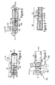
- Figure 5 is an enlarged perspective view of the strain relief boot of Figure 1
- Figure 6 is an enlarged side view of the strain relief boot of Figure 1;
- Figure 7 is an enlarged top view of the strain relief boot of Figure 1;
- Figure 8 is a cross-sectional view of the strain relief boot of Figure 1, taken along line B-B of Figure 6;
- Figure 9 is a side view of the strain relief boot of Figure 1 in a high side load state
- Figure 10 is a side view of the strain relief boot of Figure 1 in a low side load state
- Figure 11 is a top perspective view of the fiber optic connector of Figures 1-4, shown with the strain relief boot in a 0 degree boot orientation;
- Figure 12 is a top perspective view of the fiber optic connector of Figures 1-4, shown with the strain relief boot in a 90 degree boot orientation;
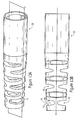
- Figures 13A and 13B are perspective and side views of an alternative embodiment of a strain relief boot
- Figures 14A and 14B are perspective and side views of another alternative embodiment of a strain relief boot.
- Figures 15A and 15B are perspective and side views of another alternative embodiment of a strain relief boot
- Figure 16 and 17 are alternative side views of the strain relief boots of Figures 6 and 13B, respectively.
- Figure 18 is a side view of an alternative embodiment of the strain relief boot of Figure 13B.
- An embodiment of the present invention provides a segmented strain relief boot that is capable of enduring a wide range of side loads, e.g. 0-14 N, and that limits a cable bend radius, e.g. to prevent undesirable degradation of optical performance of a corresponding fiber optic cable. More specifically, the strain relief boot provides a staged bending characteristic in that there is a first discrete zone configured to bend at lower side loads, and a second discrete zone configured to bend at higher side loads. Preferably, each zone has a different minimum bend radius. A cable connector assembly including such a strain relief boot is also provided.
- an exemplary fiber optic cable assembly 10 that includes a connector 20 for connecting a cable to a receptacle, and an exemplary strain relief boot 30 in accordance with the present invention.
- the connector 20 is an LC style fiber optic connector.
- the exemplary LC connector is representative of other fiber optic connectors in that it includes a connector body 22 having a termination portion 24 to which an optical fiber (cable) 6 is terminated and enclosed in a crimp eyelet and/or heat shrink tubing 26 according to conventional fiber termination and connectorization methods that are well known in the art.
- the strain relief boot 30 may be used with and/or configured for use with any suitable fiber optic connector, such as LC, FC, MU, SC and ST style connectors.
- strain relief boot may be adapted for mating with connectors and cables in other than fiber optic applications for general strain relief, although adherence to bend radius limits may not be as critical in such other applications.
- the exemplary strain relief boot 30 fits over a junction of the connector 20 and cable 6, and is fixedly attached to the connector 20 adjacent its termination portion 24, e.g. by interference fit or adhesive bonding to the crimp eyelet/heat shrink assembly that is fixed to the connector body 22, as shown in Figure 4.
- the strain relief boot may be constructed of conventional materials, such as polypropylene, using conventional manufacturing methods, such as a conventional injection molding process.
- the exemplary boot 30 includes an elongated sleeve member 32 defining a central channel 34 extending along a longitudinal axis Z of the sleeve member.
- the channel 34 is dimensioned to receive a cable, such as a clad optical fiber cladding, etc., so that the boot 30 may be passed over and enclose the cable and be mounted to a connector, as is typical of strain relief boots.
- the sleeve 30 includes a relatively flexible bend limiting portion 36 and a relatively less flexible mounting portion 38.
- the mounting portion 38 is used to mount the boot 30, i.e. a distal portion of the sleeve member, to the connector 20 by interference/friction fit, adhesion, etc., as discussed above.
- the bend limiting portion 36 includes multiple links 40, which are separated from one another by gaps 42, which are openings in the structure of the sleeve 30. Such openings may be formed during manufacture, e.g. injection molding, of the sleeve 30.
- the gaps 42 are spaced from one another in a direction of the longitudinal axis Z, and thus define the links 40 between them.
- each of the links is generally annular in cross-sectional shape, as shown in Figures 1-15. This contributes to rotational symmetry of the strain relief boot, as discussed in greater detail below.
- alternative shapes may be used, as will be appreciated by those skilled in the art.
- gaps 42 are preferably oriented transversely to one another.
- the gaps may be positioned at distinct peripheral, e.g. circumferential, positions separated by a predefined angular interval relative to the longitudinal axis Z.
- gaps 42a and 42b, and others of the gaps are positioned at a regular angular interval of 90 degrees between axially adjacent gaps, as best shown in Figure 5. This configuration contributes to rotational symmetry of the boot 30.
- the bend limiting portion 36 of the sleeve member 30 includes ribs 46 extending in the direction of the longitudinal axis to connect adjacent links.
- rib 46a connects links 40a and 40b, and is defined between gaps 42a, 42c, as shown in Figure 5.
- ribs e.g. 46a, 46b, extending in opposed positions about the sleeve member 30 between adjacent links, e.g. 40a, 40b, as best shown in Figures 6 and 7.
- the ribs, e.g. 46a, 46b, on axially opposite sides of each link are preferably positioned at distinct peripheral positions separated by a predefined angular interval, e.g. 180 degrees as shown in Figures 5-8. This configuration contributes to a rotational symmetry of the boot 30, as discussed in greater detail below.
- the strain relief boot 30 provides a staged bending characteristic in that there is a first discrete zone configured to bends at lower side loads, and a second discrete zone configured to bend at higher side loads.
- each zone has a different minimum bend radius.
- Differences in bending characteristics and bend radii among the zones are due at least in part to structural differences in the sleeve.
- Such structural differences may include one or more of differences in widths of the gaps in the longitudinal direction, differences in widths of links in the longitudinal direction, differences in lengths of connecting ribs in a peripheral direction, and/or differences in outside diameter of the boot due to taper.
- each of the gaps 42 has a respective width in the direction of the longitudinal axis Z.
- a first gap has a width G 1 that is greater than a second width G 2 of a second gap.
- G 1 may be 0.8 mm
- G 2 may be 0.6 mm.
- the second gap 42c is closer to the sleeve member's mounting portion 38 than the first gap 42d, as shown in Figure 7. Accordingly, a proximal end portion 36a of the bend limiting portion 36 will be more flexible than a distal end portion 36b of the bend limiting portion 36.
- the boot As the boot starts to bend it is relatively more flexible due to the presence of relative large gaps between links. This flexibility is sustained until the gaps of smaller widths, G2, start to close, at which time the boot becomes less flexible and limits the radius of the bend to a desired minimum. Gaps of larger width, G1 may not close under any side load condition, therefore the boot portion at that end remains flexible. This is especially useful for lower loads for which the flexible links at the proximal end smooth the boot to cable transition, avoiding a sharp bend radius.
- links 40a, 40d of the sleeve member 30 that have different widths in the direction of the longitudinal axis Z.
- the width L1 of link 40a is greater than the width L2 of link 40d.
- L1 may be 1.2 mm and L2 may be 0.9 mm.
- a group of narrower links allows a tighter bend, i.e. smaller minimum bend radius, relative to a group of identically spaced wider links.
- the wider link 40a is closer to the sleeve member's mounting portion 38 than the narrower link 40d, as shown in Figure 7.
- a proximal end portion 36a of the bend limiting portion 36 will have a smaller minimum bend radius than the distal end portion 36b. Accordingly, longitudinal segments of links 40 and gaps 42 that have different link widths will have different respective minimum bend radii.
- the sleeve member 30 includes ribs 46 that extend in the direction of the longitudinal axis Z and connect adjacent links 40.
- Each of the ribs 46 has a respective length along a periphery (e.g., circumferentially) of the sleeve member 30.
- the peripheral length of the ribs may be different at different axial locations along the length of the boot 30.
- rib 46a may have a length R 1 that is greater than a respective length R 2 of another rib 46d, as best shown in Figure 6.
- a rib 46a having a longer length is closer to the sleeve member's mounting portion 38 than a rib 46b having a shorter length, as shown in Figure 7.
- a proximal end portion 36a of the bend limiting portion 36 will be more flexible, i.e. bend under a lower side load, than the distal end portion 36b, in part because the longer ribs include more sleeve material and impart greater stiffness to a corresponding portion of the sleeve member 30.
- longitudinal segments of the boot 30 that have different rib lengths will have different bend characteristics under side loads.
- Figures 9 and 10 are side views of the strain relief boot 30 of Figure 1 in a high side load (e.g., 9-14 N) and low side load (e.g., 0-4 N) states, respectively.
- the side load is applied in the direction X, which is approximately perpendicular to a longitudinal axis of the connector.
- the exemplary strain relief boot 30 bends primarily toward the proximal end portion 36a of the bend limiting portion 36. This is where flexibility is relatively higher due to larger gaps between links, narrower links and/or shorter ribs, relative to those near the distal end portion 36b, as discussed above.
- the more rigid distal end portion 36b may not, or may only slightly, bend at lower side loads.
- the exemplary strain relief boot 30 bends primarily, and/or more significantly, toward the distal end portion 36b of the bend limiting portion 36. This is due, at least in part, to the inability of the relatively more flexible portion of the bend limiting portion 36 to accept the greater load. Note that gaps in the more flexible proximal end portion 36a that are partially closed under a lower load may re-open under higher a load, e.g. as shown at Y in Figures 9 and 10. This increases the actual bend radius in the proximal end portion 36a, resulting in a more gradual bend in this region, as the actual bend radius in the distal end portion 36b decreases, resulting in a tighter bend in this region.
- the bending characteristics of the boot includes a first stage in which lighter loads result primarily in bending in a proximal portion of the boot, and a second stage in which heavier loads result in subsequent bending in a distal portion of the boot.
- Figures 11 and 12 are top perspective views of the exemplary fiber optic connector of Figures 1-4, shown with the strain relief boot in a 0 degree rotational orientation ( Figure 11) and a 90 degree rotational orientation (Figure 12) relative to a longitudinal axis of the connector. It is noted that there is a like number of links in a plane of a bend of the cable in both the 0 and 90 degree rotational orientations, which means that there is a degree of rotational symmetry to the exemplary boot 30.
- the rotational symmetry of the boot 30 provides consistent, or substantially similar, bend characteristics and change in internal transmittance (CIT) values.
- CIT internal transmittance
- the effective number of gaps activated is increased. While the introduction of more active gaps in the plane of the bend tends to make the boot more flexible, the ultimate flexibility of each gap is also a function of the proximity of the bend plane to the closed end of the gap, which in turn is related to the orientation of the boot. Gaps are most flexible when the boot orientation is close to 0 and 90 degrees, and least flexible when the boot orientation is close to 45 degrees. Furthermore, the number of active gaps is least when the boot orientation is close to 0 and 90 degrees, and most when the boot orientation is close to 45 degrees.
- each is stiffer, thereby making the overall boot bend characteristics approximately invariant with boot orientation, across a 360 degree range of rotational orientations of the boot 30 relative to the connector 20.
- This is advantageous because it reduces or eliminates the need for the boot 30 to be oriented in a specific orientation during mounting to a connector 20, and/or the need to predetermine a direction from which loads will be applied to the boot 30.
- the exemplary embodiment provides for a similar bend characteristic due at least in part to relatively less stiffness of a larger number of links, or relatively greater stiffness of a lesser number of links in the plane of the bend.
- the boot allows for adherence to minimum bend radius limitations of optical fibers to ensure adequate optical performance while having an overall shorter length, e.g. approximately 20% shorter overall, from a tip of a connector ferrule to a proximal end of the strain relief boot.
- an overall length of 42.5 mm has been achieved, relative to a conventional overall length of 52 mm.
- the boots described above generally consist of links separated by gaps.
- the gaps are generally defined between two parallel surfaces of links that are joined by a curved surface.
- portions of the links 40 are contoured, such that each gap 42 has a non-rectangular shape when viewed transversely, i.e. when viewed as shown in Figures 2 or 3.
- the links may be tapered in the radial direction, such that the gaps 42 between links have either a generally chevron or wedge shape, in which the distal ends of adjacent links are more widely spaced in the longitudinal direction than their proximal ends relative to a reference plane P, as shown in Figures 13A and 13B.
- the links may be flared in the radial direction, such that the gaps 42 between links have a generally inverted chevron or inverted wedge shape, in which the distal ends of adjacent links are more closely spaced than their proximal ends relative to a reference plane P, as shown in Figures 14A and 14B.
- junctions of links, ribs, etc. of any configuration may have rounded, radiused, chamfered, or other eased edges 45 or junctions 43 at which they intersect one another, as shown in Figures 15A and 15B.
- These variations contribute and/or control the bend limits, the overall flexibility of the boot, and the relationship of staged bending in the different zones. Accordingly, these features can be used, combined and/or varied to provide desired bending characteristics for a particular boot 30.
- the internal geometry of the boots of Figures 1-15B is essentially cylindrical, as best shown in Figure 16 and 17.
- the links close at their radially distal ends, with the edges "A" coming in contact to limit the bent shape of the boot, as best shown in Figure 16.
- the internal geometry of the boot 30 in a bent state is essentially a series of adjacent straight segments, which provides a segmented surface.
- the edges/corners (see A, Figure 16) have a radius of curvature or other feature that is different from that of the intended design, or that differs from one cavity of the mold to another, then the bent shape of the boot may not conform precisely to design specifications.
- the contoured portions of the links are defined so that more than just edges/corners of adjacent links abut one another at or near the bend limit.
- substantially planar surfaces are provided for abutting one another at or near the bend limit. Such surfaces can be more reliably provided in an injection molding process, which allows for better conformance to design specifications.
- the chamfered edge surfaces 45 of Figures 15A and 15B abut one another at or near the bend limit, and a substantial portion of the opposing substantially planar link surfaces 45 of Figures 13A and 13B abut one another at or near the bend limit (see B in Figure 17).
- Such embodiments allow for substantially planar surfaces, and not just sharp edges/corners, to abut one another at or near the bend limit. This provides a more solid "stop" for the bending action of the boot, eliminates the sensitivity of the boot design to the shape of the edges "A", and thus may provide a more reliable, more predictable bend limit and bend limit configuration.
- the cylindrical internal geometry of Figures 1-17 which provides a series of adjacent straight segments differing in slope, might in certain embodiments pose a risk of transmission loss if boot is designed such that the transition from one segment may cause an excessively sharp bend in the fiber when the boot is in its bent shape.
- an alternative embodiment is provided, as shown in Figure 18.
- the interior surface 33 of the boot defines a series of arcs that, when bent under high load, form a continuous arc. Accordingly, a fiber within the boot 30 follows the smooth curve of the interior surface's continuous arc when the boot is in a bent state, e.g. at its bend limit.
- the external geometry may be such that the boot's external surface 35 defines a series of arcs corresponding to the arc along the interior surface, as shown in Figure 18.
- the external geometry will also define a continuous arc when the boot is in a bent state, e.g. at its bend limit. This results in a uniform wall thickness for the bent boot.
Landscapes
- Physics & Mathematics (AREA)
- General Physics & Mathematics (AREA)
- Optics & Photonics (AREA)
- Details Of Connecting Devices For Male And Female Coupling (AREA)
- Light Guides In General And Applications Therefor (AREA)
Abstract
A strain relief boot for a cable connector comprises an elongated sleeve member defining a central channel. The central channel extends along a longitudinal axis (Z) and is dimensioned to receive a cable. The sleeve member comprises a bend limiting portion and a mounting portion (38). The bend limiting portion comprises a plurality of links (40a, 40b, 40d) separated by a plurality of gaps (42c, 42d) spaced in a direction of the longitudinal axis (Z). Each of the plurality of gaps (42c, 42d) has a respective width (G1, G2) in the direction of the longitudinal axis (Z). A first gap (42d) of the plurality of gaps has a first width (G1) that is greater than a second width (G2) of a second gap (42c) of the plurality of gaps.
Description
- The present invention relates generally to strain relief for cables, and more particularly to a strain relief boot for a fiber optic or other cable and/or connector.
- Cables, including optical fibers, are commonly used in a variety of applications, including telecommunications applications. The fibers may be terminated to any of a variety of different connectors, such as LC, FC, MU, SC and ST type connectors. Such connectors are used to join fibers to active or passive optical components such as sources, detectors, repeaters, switches, attenuators, etc.
- Cables may be subject to excessive bending when side loads are placed on the cable. It is well known in the art that particular care is taken in fiber optic cable applications not to violate a minimum bend radius of the cable.
Excessive bending of the fiber negatively impacts the transmission characteristics of the fiber and degrades optical performance. Such loads are often relieved by a strain relief device in the form of a flexible boot, which can be used to limit the bend radius to prevent or limit excessive bending and related degradation of optical performance. - Various strain relief devices for fiber optic cables and/or connectors are known in the art.
U.S. Patent No. 5,390,272 to Repta et al. discloses an exemplary strain relief boot of a segmented design that includes an overlapping, alternately positioned, staggered series of cut openings, alternate ones of which define a series of ribs each including a transverse opening, alternate ribs being bendable in transverse directions. The ribs are spaced apart by connecting portions defined by openings. The ribs, cut openings and connecting portions each have a respective uniform width along the axial direction of the boot. - While some strain relief devices and/or connectors may be suitable for certain applications, e.g. where there is ample environmental space, they are unsuitable for applications in which space is limited. For example, optical equipment is often mounted in a telecommunications cabinet having a hinged cover. Due to the combined length of existing strain relief devices and connectors, there is sometimes insufficient clearance space between a front face of the components and an inside face of the cover when the cover is closed. As a result, the cover cannot be closed, or optical performance is degraded as the closed cover impinges upon the strain relief devices and causes bending of the fiber/strain relief device.
- What is needed is a strain relief device that is capable of enduring a wide range of side loads, e.g. 0-14 Newtons, and limiting the cable bend radius to prevent undesirable degradation of optical performance of a corresponding fiber optic cable.
- This problem is solved by a strain relief boot according to claim 1.
- The invention is a strain relief boot for a cable connector comprising an elongated sleeve member defining a central channel. The central channel extends along a longitudinal axis and is dimensioned to receive a cable. The sleeve member comprises a bend limiting portion and a mounting portion. The bend limiting portion comprises a plurality of links separated by a plurality of gaps spaced in a direction of the longitudinal axis. Each of the plurality of gaps has a respective width in the direction of the longitudinal axis. A first gap of the plurality of gaps has a first width that is greater than a second width of a second gap of the plurality of gaps.
- The present invention will now be described by way of example with reference to the following drawings in which:
- Figure 1 is an exploded view of an exemplary fiber optic cable assembly including an exemplary strain relief boot in accordance with the present invention;
- Figures 2 and 3 are top and side views of the fiber optic cable assembly of Figure 1;
- Figure 4 is a cross sectional view of the fiber optic cable assembly of Figure 1, taken along line A-A of Figure 2;
- Figure 5 is an enlarged perspective view of the strain relief boot of Figure 1
- Figure 6 is an enlarged side view of the strain relief boot of Figure 1;
- Figure 7 is an enlarged top view of the strain relief boot of Figure 1;
- Figure 8 is a cross-sectional view of the strain relief boot of Figure 1, taken along line B-B of Figure 6;
- Figure 9 is a side view of the strain relief boot of Figure 1 in a high side load state;
- Figure 10 is a side view of the strain relief boot of Figure 1 in a low side load state;
- Figure 11 is a top perspective view of the fiber optic connector of Figures 1-4, shown with the strain relief boot in a 0 degree boot orientation;
- Figure 12 is a top perspective view of the fiber optic connector of Figures 1-4, shown with the strain relief boot in a 90 degree boot orientation;
- Figures 13A and 13B are perspective and side views of an alternative embodiment of a strain relief boot;
- Figures 14A and 14B are perspective and side views of another alternative embodiment of a strain relief boot; and
- Figures 15A and 15B are perspective and side views of another alternative embodiment of a strain relief boot;
- Figure 16 and 17 are alternative side views of the strain relief boots of Figures 6 and 13B, respectively; and
- Figure 18 is a side view of an alternative embodiment of the strain relief boot of Figure 13B.
- An embodiment of the present invention provides a segmented strain relief boot that is capable of enduring a wide range of side loads, e.g. 0-14 N, and that limits a cable bend radius, e.g. to prevent undesirable degradation of optical performance of a corresponding fiber optic cable. More specifically, the strain relief boot provides a staged bending characteristic in that there is a first discrete zone configured to bend at lower side loads, and a second discrete zone configured to bend at higher side loads. Preferably, each zone has a different minimum bend radius. A cable connector assembly including such a strain relief boot is also provided.
- Referring now to Figures 1-4, an exemplary fiber
optic cable assembly 10 is shown that includes aconnector 20 for connecting a cable to a receptacle, and an exemplarystrain relief boot 30 in accordance with the present invention. In this exemplary embodiment, theconnector 20 is an LC style fiber optic connector. The exemplary LC connector is representative of other fiber optic connectors in that it includes aconnector body 22 having atermination portion 24 to which an optical fiber (cable) 6 is terminated and enclosed in a crimp eyelet and/orheat shrink tubing 26 according to conventional fiber termination and connectorization methods that are well known in the art. However, it will be appreciated that thestrain relief boot 30 may be used with and/or configured for use with any suitable fiber optic connector, such as LC, FC, MU, SC and ST style connectors. - Additionally, it will be appreciated by those skilled in the art that the strain relief boot may be adapted for mating with connectors and cables in other than fiber optic applications for general strain relief, although adherence to bend radius limits may not be as critical in such other applications.
- As is conventional for strain relief boots, the exemplary
strain relief boot 30 fits over a junction of theconnector 20 andcable 6, and is fixedly attached to theconnector 20 adjacent itstermination portion 24, e.g. by interference fit or adhesive bonding to the crimp eyelet/heat shrink assembly that is fixed to theconnector body 22, as shown in Figure 4. Further, the strain relief boot may be constructed of conventional materials, such as polypropylene, using conventional manufacturing methods, such as a conventional injection molding process. - Referring now to Figures 5-8, enlarged views of an exemplary
strain relief boot 30 are shown. As shown in Figures 5-8, theexemplary boot 30 includes anelongated sleeve member 32 defining acentral channel 34 extending along a longitudinal axis Z of the sleeve member. Thechannel 34 is dimensioned to receive a cable, such as a clad optical fiber cladding, etc., so that theboot 30 may be passed over and enclose the cable and be mounted to a connector, as is typical of strain relief boots. - The
sleeve 30 includes a relatively flexiblebend limiting portion 36 and a relatively lessflexible mounting portion 38. Themounting portion 38 is used to mount theboot 30, i.e. a distal portion of the sleeve member, to theconnector 20 by interference/friction fit, adhesion, etc., as discussed above. - The
bend limiting portion 36 includesmultiple links 40, which are separated from one another bygaps 42, which are openings in the structure of thesleeve 30. Such openings may be formed during manufacture, e.g. injection molding, of thesleeve 30. Thegaps 42 are spaced from one another in a direction of the longitudinal axis Z, and thus define thelinks 40 between them. Preferably, each of the links is generally annular in cross-sectional shape, as shown in Figures 1-15. This contributes to rotational symmetry of the strain relief boot, as discussed in greater detail below. However, alternative shapes may be used, as will be appreciated by those skilled in the art. - In the longitudinal direction, adjacent ones of the
gaps 42 are preferably oriented transversely to one another. For example, the gaps may be positioned at distinct peripheral, e.g. circumferential, positions separated by a predefined angular interval relative to the longitudinal axis Z. In the exemplary embodiment shown, for example,gaps boot 30. - Preferably, several gaps are positioned along a perimeter of the
sleeve member 30 for each axial location, as shown in Figures 5-8. For example, there are two gaps, 42a, 42c positioned along the perimeter of the sleeve between axiallyadjacent links bend limiting portion 36 of thesleeve member 30 includesribs 46 extending in the direction of the longitudinal axis to connect adjacent links. For example,rib 46a connectslinks gaps - Preferably, there is a respective pair of ribs, e.g. 46a, 46b, extending in opposed positions about the
sleeve member 30 between adjacent links, e.g. 40a, 40b, as best shown in Figures 6 and 7. The ribs, e.g. 46a, 46b, on axially opposite sides of each link are preferably positioned at distinct peripheral positions separated by a predefined angular interval, e.g. 180 degrees as shown in Figures 5-8. This configuration contributes to a rotational symmetry of theboot 30, as discussed in greater detail below. - As discussed above, the
strain relief boot 30 provides a staged bending characteristic in that there is a first discrete zone configured to bends at lower side loads, and a second discrete zone configured to bend at higher side loads. Preferably, each zone has a different minimum bend radius. Differences in bending characteristics and bend radii among the zones are due at least in part to structural differences in the sleeve. Such structural differences may include one or more of differences in widths of the gaps in the longitudinal direction, differences in widths of links in the longitudinal direction, differences in lengths of connecting ribs in a peripheral direction, and/or differences in outside diameter of the boot due to taper. - Referring now to Figures 6 and 7, exemplary structural differences are described for illustrative purposes. As described above, each of the
gaps 42 has a respective width in the direction of the longitudinal axis Z. In the exemplary embodiment, a first gap has a width G1 that is greater than a second width G2 of a second gap. For example, G1 may be 0.8 mm, and G2 may be 0.6 mm. Preferably, thesecond gap 42c is closer to the sleeve member's mountingportion 38 than thefirst gap 42d, as shown in Figure 7. Accordingly, aproximal end portion 36a of thebend limiting portion 36 will be more flexible than adistal end portion 36b of thebend limiting portion 36. As the boot starts to bend it is relatively more flexible due to the presence of relative large gaps between links. This flexibility is sustained until the gaps of smaller widths, G2, start to close, at which time the boot becomes less flexible and limits the radius of the bend to a desired minimum. Gaps of larger width, G1 may not close under any side load condition, therefore the boot portion at that end remains flexible. This is especially useful for lower loads for which the flexible links at the proximal end smooth the boot to cable transition, avoiding a sharp bend radius. - Further, having
larger gaps 42 betweenlinks 40 toward aproximal end portion 36a than adistal end portion 36b of thebend limiting portion 36 permits a sharper bend of the strain relief boot, i.e. a smaller minimum bend radius for the boot, in the region oflarger gaps 42. This is due to the geometry of the segmented design that allows for bending of thesleeve member 30 until a point at whichadjacent links 40 abut one another, at which point further bending between those links essentially ceases; a larger gap between adjacent links allows for more bending (a shorter bend radius) before the adjacent links abut one another. Accordingly, longitudinal segments oflinks 40 andgaps 42 that have different gap widths will have different respective minimum bend radii. - In the exemplary embodiment, there are additional structural variations that contribute to the staged bending characteristic of the
boot 30. As shown in Figures 6 and 7, there arelinks sleeve member 30 that have different widths in the direction of the longitudinal axis Z. For example the width L1 oflink 40a is greater than the width L2 oflink 40d. For example, L1 may be 1.2 mm and L2 may be 0.9 mm. A group of narrower links allows a tighter bend, i.e. smaller minimum bend radius, relative to a group of identically spaced wider links. Preferably, thewider link 40a is closer to the sleeve member's mountingportion 38 than thenarrower link 40d, as shown in Figure 7. In such a configuration, aproximal end portion 36a of thebend limiting portion 36 will have a smaller minimum bend radius than thedistal end portion 36b. Accordingly, longitudinal segments oflinks 40 andgaps 42 that have different link widths will have different respective minimum bend radii. - In the exemplary embodiment, there are yet additional structural variations that contribute to the staged bending characteristic of the
boot 30. As shown in Figures 6 and 7, thesleeve member 30 includesribs 46 that extend in the direction of the longitudinal axis Z and connectadjacent links 40. Each of theribs 46 has a respective length along a periphery (e.g., circumferentially) of thesleeve member 30. To vary the bending characteristics along the length of theboot 30, the peripheral length of the ribs may be different at different axial locations along the length of theboot 30. For example,rib 46a may have a length R1 that is greater than a respective length R2 of anotherrib 46d, as best shown in Figure 6. Preferably, arib 46a having a longer length is closer to the sleeve member's mountingportion 38 than arib 46b having a shorter length, as shown in Figure 7. In such a configuration, aproximal end portion 36a of thebend limiting portion 36 will be more flexible, i.e. bend under a lower side load, than thedistal end portion 36b, in part because the longer ribs include more sleeve material and impart greater stiffness to a corresponding portion of thesleeve member 30. Accordingly, longitudinal segments of theboot 30 that have different rib lengths will have different bend characteristics under side loads. - Figures 9 and 10 are side views of the
strain relief boot 30 of Figure 1 in a high side load (e.g., 9-14 N) and low side load (e.g., 0-4 N) states, respectively. In both Figures, the side load is applied in the direction X, which is approximately perpendicular to a longitudinal axis of the connector. As shown in Figure 10, under relatively low side loads, the exemplarystrain relief boot 30 bends primarily toward theproximal end portion 36a of thebend limiting portion 36. This is where flexibility is relatively higher due to larger gaps between links, narrower links and/or shorter ribs, relative to those near thedistal end portion 36b, as discussed above. The more rigiddistal end portion 36b may not, or may only slightly, bend at lower side loads. - As shown in Figure 9, under relatively higher side loads, the exemplary
strain relief boot 30 bends primarily, and/or more significantly, toward thedistal end portion 36b of thebend limiting portion 36. This is due, at least in part, to the inability of the relatively more flexible portion of thebend limiting portion 36 to accept the greater load. Note that gaps in the more flexibleproximal end portion 36a that are partially closed under a lower load may re-open under higher a load, e.g. as shown at Y in Figures 9 and 10. This increases the actual bend radius in theproximal end portion 36a, resulting in a more gradual bend in this region, as the actual bend radius in thedistal end portion 36b decreases, resulting in a tighter bend in this region. - Accordingly, the bending characteristics of the boot includes a first stage in which lighter loads result primarily in bending in a proximal portion of the boot, and a second stage in which heavier loads result in subsequent bending in a distal portion of the boot.
- Figures 11 and 12 are top perspective views of the exemplary fiber optic connector of Figures 1-4, shown with the strain relief boot in a 0 degree rotational orientation (Figure 11) and a 90 degree rotational orientation (Figure 12) relative to a longitudinal axis of the connector. It is noted that there is a like number of links in a plane of a bend of the cable in both the 0 and 90 degree rotational orientations, which means that there is a degree of rotational symmetry to the
exemplary boot 30. The rotational symmetry of theboot 30 provides consistent, or substantially similar, bend characteristics and change in internal transmittance (CIT) values. - Furthermore, for boot orientations between 0 and 90 degrees the effective number of gaps activated is increased. While the introduction of more active gaps in the plane of the bend tends to make the boot more flexible, the ultimate flexibility of each gap is also a function of the proximity of the bend plane to the closed end of the gap, which in turn is related to the orientation of the boot. Gaps are most flexible when the boot orientation is close to 0 and 90 degrees, and least flexible when the boot orientation is close to 45 degrees. Furthermore, the number of active gaps is least when the boot orientation is close to 0 and 90 degrees, and most when the boot orientation is close to 45 degrees. Therefore, although the number of active gaps is increased for boot orientations between 0 and 90, each is stiffer, thereby making the overall boot bend characteristics approximately invariant with boot orientation, across a 360 degree range of rotational orientations of the
boot 30 relative to theconnector 20. This is advantageous because it reduces or eliminates the need for theboot 30 to be oriented in a specific orientation during mounting to aconnector 20, and/or the need to predetermine a direction from which loads will be applied to theboot 30. - Further, although there is a different number of links in the same plane of the bend of the cable when the boot is in a 45 degree rotational orientation, the exemplary embodiment provides for a similar bend characteristic due at least in part to relatively less stiffness of a larger number of links, or relatively greater stiffness of a lesser number of links in the plane of the bend.
- Further still, the boot allows for adherence to minimum bend radius limitations of optical fibers to ensure adequate optical performance while having an overall shorter length, e.g. approximately 20% shorter overall, from a tip of a connector ferrule to a proximal end of the strain relief boot. In the example of an LC connector, an overall length of 42.5 mm has been achieved, relative to a conventional overall length of 52 mm.
- The boots described above generally consist of links separated by gaps. In the embodiments of Figures 1-12, the gaps are generally defined between two parallel surfaces of links that are joined by a curved surface. In certain alternative embodiments (see Figures 13A-16), portions of the
links 40 are contoured, such that eachgap 42 has a non-rectangular shape when viewed transversely, i.e. when viewed as shown in Figures 2 or 3. - For example, the links may be tapered in the radial direction, such that the
gaps 42 between links have either a generally chevron or wedge shape, in which the distal ends of adjacent links are more widely spaced in the longitudinal direction than their proximal ends relative to a reference plane P, as shown in Figures 13A and 13B. - Alternatively, the links may be flared in the radial direction, such that the
gaps 42 between links have a generally inverted chevron or inverted wedge shape, in which the distal ends of adjacent links are more closely spaced than their proximal ends relative to a reference plane P, as shown in Figures 14A and 14B. - Further, it should be noted that junctions of links, ribs, etc. of any configuration may have rounded, radiused, chamfered, or other eased
edges 45 orjunctions 43 at which they intersect one another, as shown in Figures 15A and 15B. These variations contribute and/or control the bend limits, the overall flexibility of the boot, and the relationship of staged bending in the different zones. Accordingly, these features can be used, combined and/or varied to provide desired bending characteristics for aparticular boot 30. - The internal geometry of the boots of Figures 1-15B is essentially cylindrical, as best shown in Figure 16 and 17. When such boots are bent under high load, the links close at their radially distal ends, with the edges "A" coming in contact to limit the bent shape of the boot, as best shown in Figure 16. As a result, the internal geometry of the
boot 30 in a bent state is essentially a series of adjacent straight segments, which provides a segmented surface. - While this configuration is satisfactory for certain applications, it is noted that if the edges/corners (see A, Figure 16) have a radius of curvature or other feature that is different from that of the intended design, or that differs from one cavity of the mold to another, then the bent shape of the boot may not conform precisely to design specifications. Accordingly, in an alternative embodiment, the contoured portions of the links are defined so that more than just edges/corners of adjacent links abut one another at or near the bend limit. Instead, substantially planar surfaces are provided for abutting one another at or near the bend limit. Such surfaces can be more reliably provided in an injection molding process, which allows for better conformance to design specifications. For example, the chamfered edge surfaces 45 of Figures 15A and 15B abut one another at or near the bend limit, and a substantial portion of the opposing substantially planar link surfaces 45 of Figures 13A and 13B abut one another at or near the bend limit (see B in Figure 17). Such embodiments allow for substantially planar surfaces, and not just sharp edges/corners, to abut one another at or near the bend limit. This provides a more solid "stop" for the bending action of the boot, eliminates the sensitivity of the boot design to the shape of the edges "A", and thus may provide a more reliable, more predictable bend limit and bend limit configuration.
- Further, the cylindrical internal geometry of Figures 1-17, which provides a series of adjacent straight segments differing in slope, might in certain embodiments pose a risk of transmission loss if boot is designed such that the transition from one segment may cause an excessively sharp bend in the fiber when the boot is in its bent shape. Accordingly, an alternative embodiment is provided, as shown in Figure 18. In this alternative embodiment, the
interior surface 33 of the boot defines a series of arcs that, when bent under high load, form a continuous arc. Accordingly, a fiber within theboot 30 follows the smooth curve of the interior surface's continuous arc when the boot is in a bent state, e.g. at its bend limit. Optionally, the external geometry may be such that the boot'sexternal surface 35 defines a series of arcs corresponding to the arc along the interior surface, as shown in Figure 18. In such an embodiment, the external geometry will also define a continuous arc when the boot is in a bent state, e.g. at its bend limit. This results in a uniform wall thickness for the bent boot.
Claims (7)
- A strain relief boot (30) for a cable connector (20) comprising an elongated sleeve member (32) defining a central channel (34), said central channel (34) extending along a longitudinal axis (Z) and being dimensioned to receive a cable (6), said sleeve member (32) comprising a bend limiting portion (36) and a mounting portion (38), said bend limiting portion (36) comprising a plurality of links (40) separated by a plurality of gaps (42) spaced in a direction of said longitudinal axis (Z), each of said plurality of gaps (42) having a respective width (G1, G2) in the direction of the longitudinal axis (Z), characterized in that:a first gap (42d) of said plurality of gaps has a first width (G1) that is greater than a second width (G2) of a second gap (42c) of said plurality of gaps.
- The strain relief boot of claim 1, wherein said second gap (42c) is closer to said mounting portion (38) than said first gap (42d).
- The strain relief boot (30) of claim 1, wherein adjacent ones of said plurality of gaps (42) are oriented transversely to one another.
- The strain relief boot (30) of claim 3, wherein adjacent ones of said plurality of gaps (42) are positioned at distinct peripheral positions separated by a predefined angular interval relative to said longitudinal axis (Z).
- The strain relief boot (30) of claim 4, wherein the predefined angular interval between adjacent ones of said plurality of gaps (42) is about 90 degrees.
- The strain relief boot (30) of claim 3, wherein each of said plurality of links (40) is annular in shape, said bend limiting portion (36) further comprising a plurality of ribs (46), each of said plurality of ribs extending in the direction of said longitudinal axis (Z) to connect adjacent ones of said plurality of links (40), a respective pair of said plurality of ribs (46) extending in opposed positions about the sleeve member (32) between adjacent ones of said plurality of links (40), ribs (46) on axially opposite sides of each link (40) being positioned at distinct peripheral positions separated by a predefined angular interval.
- The strain relief boot (30) of claim 6, wherein the predefined angular interval between ribs (46) on axially opposite sides of each link (40) is about 180 degrees.
Applications Claiming Priority (1)
| Application Number | Priority Date | Filing Date | Title |
|---|---|---|---|
| US11/461,258 US7677812B2 (en) | 2006-07-31 | 2006-07-31 | Strain relief boot for cable connector |
Publications (1)
| Publication Number | Publication Date |
|---|---|
| EP1885031A1 true EP1885031A1 (en) | 2008-02-06 |
Family
ID=38515818
Family Applications (1)
| Application Number | Title | Priority Date | Filing Date |
|---|---|---|---|
| EP07113321A Withdrawn EP1885031A1 (en) | 2006-07-31 | 2007-07-27 | Strain relief boot for cable connector |
Country Status (4)
| Country | Link |
|---|---|
| US (1) | US7677812B2 (en) |
| EP (1) | EP1885031A1 (en) |
| CN (1) | CN101136545B (en) |
| CA (1) | CA2595146C (en) |
Cited By (2)
| Publication number | Priority date | Publication date | Assignee | Title |
|---|---|---|---|---|
| FR2952119A1 (en) * | 2009-11-04 | 2011-05-06 | Intelliserv Int Holding Ltd | TRANSDUCER DEVICE HAVING A HOUSING FOR AN EFFORT REPLY COIL |
| GB2482058A (en) * | 2010-07-14 | 2012-01-18 | Bosch Gmbh Robert | Cable anti-kink unit comprising bending-line adjusting means |
Families Citing this family (60)
| Publication number | Priority date | Publication date | Assignee | Title |
|---|---|---|---|---|
| US7785252B2 (en) * | 2004-11-23 | 2010-08-31 | Novare Surgical Systems, Inc. | Articulating sheath for flexible instruments |
| US7534050B2 (en) | 2007-04-13 | 2009-05-19 | Adc Telecommunications, Inc. | Field terminatable fiber optic connector assembly |
| US8408811B2 (en) * | 2007-07-16 | 2013-04-02 | Corning Cable Systems Llc | Fusion-splice fiber optic connectors and related tools |
| CN102439502B (en) * | 2009-04-06 | 2015-02-18 | Adc电信公司 | Fiber optic connector and method for assembling |
| US7942591B2 (en) * | 2009-04-07 | 2011-05-17 | Tyco Electronics Corporation | Bend limiting boot |
| FR2952480B1 (en) * | 2009-11-06 | 2012-05-25 | Snecma | INSERT FOR PROTECTION AGAINST WEAR OF DRIVERS OF AN ELECTRICAL HARNESS |
| US9728926B2 (en) | 2010-11-22 | 2017-08-08 | Commscope Technologies Llc | Method and apparatus for radial ultrasonic welding interconnected coaxial connector |
| US8826525B2 (en) | 2010-11-22 | 2014-09-09 | Andrew Llc | Laser weld coaxial connector and interconnection method |
| US9761959B2 (en) | 2010-11-22 | 2017-09-12 | Commscope Technologies Llc | Ultrasonic weld coaxial connector |
| US8365404B2 (en) | 2010-11-22 | 2013-02-05 | Andrew Llc | Method for ultrasonic welding a coaxial cable to a coaxial connector |
| US9768574B2 (en) | 2010-11-22 | 2017-09-19 | Commscope Technologies Llc | Cylindrical surface spin weld apparatus |
| US8887388B2 (en) | 2010-11-22 | 2014-11-18 | Andrew Llc | Method for interconnecting a coaxial connector with a solid outer conductor coaxial cable |
| US8702323B2 (en) * | 2011-03-15 | 2014-04-22 | Adc Telecommunications, Inc. | Strain relief boot for a fiber optic connector |
| US8636425B2 (en) | 2011-03-15 | 2014-01-28 | Adc Telecommunications, Inc. | Fiber optic connector |
| US8639082B2 (en) * | 2011-04-19 | 2014-01-28 | Tyco Electronics Corporation | Fiber optic cable assembly |
| US9024191B2 (en) | 2011-10-03 | 2015-05-05 | Commscope Technologies Llc | Strain relief for connector and cable interconnection |
| US9108348B2 (en) | 2011-10-03 | 2015-08-18 | Commscope Technologies Llc | Method for molding a low pressure molded strain relief for coaxial connector interconnection |
| US9888837B2 (en) * | 2011-11-28 | 2018-02-13 | I-Tek Medical Solutions, Inc. | Fiber optic illumination device and method of manufacturing |
| EP2812741A2 (en) | 2012-02-07 | 2014-12-17 | Tyco Electronics Raychem BVBA | Cable termination assembly and method for connectors |
| SG11201405020TA (en) * | 2012-02-20 | 2014-09-26 | Adc Telecommunications Inc | Fiber optic connector, fiber optic connector and cable assembly, and methods for manufacturing |
| US9176285B2 (en) | 2012-05-03 | 2015-11-03 | Adc Telecommunications, Inc. | Fiber optic connector |
| US9304274B2 (en) | 2012-07-09 | 2016-04-05 | Avago Technologies General Ip (Singapore) Pte. Ltd. | Metal strain relief device for use in an optical communications system, an optical fiber cable that employs the strain relief device, and a method |
| US9310572B2 (en) | 2012-10-18 | 2016-04-12 | Corning Cable Systems Llc | Cable bend relief for fiber optic sub-assemblies and methods of assembling |
| TW201426070A (en) * | 2012-12-31 | 2014-07-01 | Avago Technologies General Ip | A metal strain relief device for use in an optical communications system, an optical fiber cable that employs the strain relief device, and a method |
| WO2014164880A1 (en) | 2013-03-11 | 2014-10-09 | Adc Telecommunications, Inc. | Fiber optic connector and fiber optic cable assembly with fiber optic cable anchored to boot of fiber optic connector |
| US9482826B2 (en) | 2013-03-15 | 2016-11-01 | Commscope Technologies Llc | Connector body for making crimp-less fiber optic cable connections |
| US10107431B2 (en) * | 2013-10-29 | 2018-10-23 | Swan Products, Llc | Flexible hose guard |
| CN104698547B (en) * | 2013-12-10 | 2016-04-13 | 林雨晴 | Boots for Flexible Fiber Optic Connectors |
| WO2016012356A1 (en) * | 2014-07-21 | 2016-01-28 | Te Connectivity Nederland B.V. | Fiber optic connector and fiber optic cable assembly with fiber optic cable anchored to boot of fiber optic connector |
| CN204359973U (en) * | 2015-01-21 | 2015-05-27 | 泰科电子(上海)有限公司 | The optical fiber connector |
| CN104617625A (en) * | 2015-02-07 | 2015-05-13 | 邹中霞 | Connector of charger |
| US9658409B2 (en) | 2015-03-03 | 2017-05-23 | Senko Advanced Components, Inc. | Optical fiber connector with changeable polarity |
| US10158194B2 (en) | 2016-01-15 | 2018-12-18 | Senko Advanced Components, Inc. | Narrow width adapters and connectors with spring loaded remote release |
| US9857540B2 (en) * | 2016-02-16 | 2018-01-02 | Corning Optical Communications LLC | Strain relief boot and fiber optic cable assembly including the same |
| JP2017216204A (en) * | 2016-06-02 | 2017-12-07 | 住友電装株式会社 | Charging connector |
| US9726830B1 (en) | 2016-06-28 | 2017-08-08 | Senko Advanced Components, Inc. | Connector and adapter system for two-fiber mechanical transfer type ferrule |
| US10350655B2 (en) | 2016-07-21 | 2019-07-16 | Douglas Miranda | Universal glass pipe cleaner |
| US10228521B2 (en) | 2016-12-05 | 2019-03-12 | Senko Advanced Components, Inc. | Narrow width adapters and connectors with modular latching arm |
| US10361507B2 (en) * | 2017-05-31 | 2019-07-23 | Zaytoun Industries | Device for protection of electronic device charging cord |
| US12571977B2 (en) | 2017-06-28 | 2026-03-10 | Corning Research & Development Corporation | Multiports and other devices having optical connection ports with securing features and methods of making the same |
| HRP20220022T1 (en) | 2017-06-28 | 2022-04-01 | Corning Research & Development Corporation | Compact fiber optic connectors |
| US10281669B2 (en) | 2017-07-14 | 2019-05-07 | Senko Advance Components, Inc. | Ultra-small form factor optical connectors |
| US12001064B2 (en) | 2017-07-14 | 2024-06-04 | Senko Advanced Components, Inc. | Small form factor fiber optic connector with multi-purpose boot |
| US11822133B2 (en) | 2017-07-14 | 2023-11-21 | Senko Advanced Components, Inc. | Ultra-small form factor optical connector and adapter |
| CN110187443B (en) * | 2018-02-23 | 2021-07-30 | 中航光电科技股份有限公司 | Fiber optic connector tail accessories, fiber optic connectors and fiber optic cable assemblies |
| US10770831B2 (en) | 2018-03-30 | 2020-09-08 | Western Technology, Inc. | Strain relief hose barb cable connector |
| CN109036644A (en) * | 2018-08-09 | 2018-12-18 | 安徽华上电缆科技有限公司 | A kind of cable resistant to bending |
| CN113631976B (en) | 2019-03-28 | 2023-06-09 | 扇港元器件有限公司 | Fiber optic adapter assembly |
| US12055768B2 (en) | 2019-06-10 | 2024-08-06 | Commscope Technologies Llc | Strain relief boot |
| US10845542B1 (en) | 2019-08-19 | 2020-11-24 | Afl Telecommunications Llc | Cable node transition assemblies |
| EP4158401A1 (en) | 2020-05-26 | 2023-04-05 | Corning Research & Development Corporation | Fiber optic connectors having one or more securing buttons |
| CN111722323A (en) * | 2020-07-20 | 2020-09-29 | 深圳市海创光通信技术有限公司 | Fiber connector with tail sleeve capable of being bent at will |
| US11604320B2 (en) | 2020-09-30 | 2023-03-14 | Corning Research & Development Corporation | Connector assemblies for telecommunication enclosures |
| PL4237889T3 (en) | 2020-10-30 | 2026-01-26 | Corning Research & Development Corporation | FEMALE FIBER OPTIC CONNECTORS WITH LOCKING ARM WITH ROCKING MECHANISM |
| EP4252055B1 (en) | 2020-11-25 | 2026-06-03 | Corning Research & Development Corporation | Multiports and other devices having optical connection ports with rotating actuators pivotly mounted and methods of making the same |
| US11880076B2 (en) | 2020-11-30 | 2024-01-23 | Corning Research & Development Corporation | Fiber optic adapter assemblies including a conversion housing and a release housing |
| US11686913B2 (en) | 2020-11-30 | 2023-06-27 | Corning Research & Development Corporation | Fiber optic cable assemblies and connector assemblies having a crimp ring and crimp body and methods of fabricating the same |
| EP4092317B1 (en) * | 2021-05-17 | 2023-10-25 | Tridonic GmbH & Co. KG | Strain relief concept with provision for wireless module |
| CN113433643B (en) * | 2021-06-24 | 2022-10-25 | 烽火通信科技股份有限公司 | Clamping groove for wiring in building and using method thereof |
| USD1021017S1 (en) | 2022-01-31 | 2024-04-02 | Teknor Apex Company | Strain relief device for a hose |
Citations (2)
| Publication number | Priority date | Publication date | Assignee | Title |
|---|---|---|---|---|
| EP0188041A1 (en) * | 1985-01-11 | 1986-07-23 | Sidney S. Sobin | Tapered torque strain relief |
| US5094552A (en) * | 1990-11-16 | 1992-03-10 | Amp Incorporated | Interlocking strain relief |
Family Cites Families (61)
| Publication number | Priority date | Publication date | Assignee | Title |
|---|---|---|---|---|
| US2727088A (en) * | 1954-03-23 | 1955-12-13 | Gen Electric | Strain relief for electric cords |
| US3395244A (en) * | 1967-03-14 | 1968-07-30 | Koehler Rudolph | Strain relief for electric cords |
| US3497608A (en) * | 1968-12-16 | 1970-02-24 | Honeywell Inc | Strain relieving means for flexible electrical cords |
| US4392344A (en) * | 1981-06-30 | 1983-07-12 | Central Safety Equipment Company | Chain-link cable carrier |
| US4739801A (en) * | 1985-04-09 | 1988-04-26 | Tysubakimoto Chain Co. | Flexible supporting sheath for cables and the like |
| DE3537964C1 (en) * | 1985-10-25 | 1987-02-19 | Rockwell Golde Gmbh | Cable guide for motor vehicle sliding roofs |
| US4718860A (en) * | 1986-08-14 | 1988-01-12 | Minnesota Mining And Manufacturing Company | Tapered strain relief electrical interconnection system |
| US4871318A (en) * | 1986-08-14 | 1989-10-03 | Minnesota Mining & Manufacturing Company | Tapered strain relief electrical interconnection system |
| US5181267A (en) * | 1988-02-23 | 1993-01-19 | Amp Incorporated | Sheath connector for an optical cable |
| DE3807491A1 (en) * | 1988-03-08 | 1989-09-21 | Schott Glaswerke | METHOD AND DEVICE FOR HERMETICALLY CARRYING OUT A LIGHT WAVE GUIDE |
| DE3829603A1 (en) * | 1988-09-01 | 1990-03-15 | Kontron Holding Ag | ULTRASONIC DOSCOPE DEVICE |
| US4834487A (en) * | 1988-09-29 | 1989-05-30 | Amp Incorporated | Optical connector with plastic alignment ferrule |
| US5037175A (en) * | 1990-06-11 | 1991-08-06 | Amp Incorporated | Clip for dressing of fiber optic cable within confined space |
| US5071219A (en) * | 1990-11-09 | 1991-12-10 | General Motors Corporation | Fiber optic connection system and method |
| US5108350A (en) * | 1991-03-06 | 1992-04-28 | A&A Manufacturing Co., Inc. | Conduit carrier chain |
| US5151962A (en) * | 1991-05-20 | 1992-09-29 | Fiber Delivery Concepts, Inc. | Fiber optic cable assemblies for laser delivery systems |
| JP2507194Y2 (en) * | 1991-07-31 | 1996-08-14 | 株式会社椿本チエイン | Internal partition structure of cable drag chain |
| US5170452A (en) * | 1991-09-09 | 1992-12-08 | Porta Systems Corp. | Fiber optic plug connector and adapter therefor |
| GB9123760D0 (en) | 1991-11-08 | 1992-01-02 | Stockman Anthony J | Optical fibre sheathing |
| US5214732A (en) * | 1992-01-02 | 1993-05-25 | Adc Telecommunications, Inc. | Optical fiber retention mechanism for securing optical fiber cable |
| US5261019A (en) * | 1992-01-02 | 1993-11-09 | Adc Telecommunications, Inc. | Fiber optic connector |
| US5202942A (en) * | 1992-04-03 | 1993-04-13 | Amp Incorporated | Cable termination member for fiber optic connectors having improved strain relief |
| US5340330A (en) * | 1993-08-26 | 1994-08-23 | Black & Decker Inc. | Anti-kink control for electrical cords |
| US5390272A (en) * | 1993-08-31 | 1995-02-14 | Amphenol Corporation | Fiber optic cable connector with strain relief boot |
| US5425120A (en) * | 1994-03-07 | 1995-06-13 | The Whitaker Corporation | Friction fit strain relief boot |
| US5461690A (en) * | 1994-07-29 | 1995-10-24 | At&T Ipm Corp. | Bend-limiting apparatus for a cable |
| US5620335C1 (en) * | 1995-03-17 | 2001-02-06 | Siemon Co | Boot with icon holder |
| US5638474A (en) * | 1995-08-30 | 1997-06-10 | Lucent Technologies Inc. | Anti-snag latch assembly for a connector |
| US5710851A (en) * | 1995-11-06 | 1998-01-20 | Amphenol Corporation | Strain relief system for a fiber optic connector |
| DE19544931A1 (en) * | 1995-12-01 | 1997-06-05 | Kabelschlepp Gmbh | Chain link of an energy chain with additional body |
| DE19605775C1 (en) * | 1996-02-16 | 1997-09-25 | Igus Gmbh | Energy chain with guide stop |
| US5933557A (en) * | 1996-11-19 | 1999-08-03 | Siecor Corporation | Multi-link boot assembly for cable connector |
| US6027352A (en) * | 1996-12-11 | 2000-02-22 | Byrne; Norman R. | Electrical interconnection assembly with pivotal end connector |
| JP3225202B2 (en) * | 1997-01-24 | 2001-11-05 | ヒロセ電機株式会社 | Optical connector |
| US5857046A (en) * | 1997-02-12 | 1999-01-05 | The Whitaker Corporation | Strain relief |
| US6039081A (en) * | 1997-02-12 | 2000-03-21 | Pmi Industries, Inc. | Articulated bend limiter |
| CA2226052A1 (en) * | 1997-02-13 | 1998-08-13 | Diamond Sa | Plug for an optical fiber plug connector and method of its manufacture |
| US5915056A (en) * | 1997-08-06 | 1999-06-22 | Lucent Technologies Inc. | Optical fiber strain relief device |
| US6068506A (en) * | 1998-04-21 | 2000-05-30 | Cablemaster Technologies, Co., Ltd. | Strain relief device for an electrical cable |
| DE19839575A1 (en) * | 1998-08-31 | 2000-03-09 | Kabelschlepp Gmbh | Energy guiding chain for guiding cables with spatially movable chain links |
| US6134370A (en) * | 1998-10-30 | 2000-10-17 | Siecor Operations, Llc | Fiber optic cable guide |
| KR20020036780A (en) * | 1999-05-28 | 2002-05-16 | 토드 엠. 뒤센 | Cable assembly with molded stress relief and method for making the same |
| JP3356733B2 (en) * | 1999-10-19 | 2002-12-16 | 株式会社椿本チエイン | Cable drag chain |
| US6749560B1 (en) * | 1999-10-26 | 2004-06-15 | Circon Corporation | Endoscope shaft with slotted tube |
| CA2390640A1 (en) * | 1999-11-09 | 2001-05-17 | Parker-Hannifin Corporation | Moldable plastic guard segment for a variable-length guard assembly for conduits |
| US6858005B2 (en) * | 2000-04-03 | 2005-02-22 | Neo Guide Systems, Inc. | Tendon-driven endoscope and methods of insertion |
| US6634801B1 (en) * | 2000-11-14 | 2003-10-21 | Stratos Lightwave, Inc. | Adjustable strain relief boot |
| US6565262B2 (en) * | 2000-12-14 | 2003-05-20 | Corning Cable Systems Llc | Trigger mechanism, optical cable connector including same, and method of assembling an optical cable connector |
| US6554489B2 (en) * | 2001-03-28 | 2003-04-29 | Corning Cable Systems Llc | Fiber optic cable guide and method of application |
| US20030039453A1 (en) * | 2001-08-24 | 2003-02-27 | Holmquist Marlon E. | Strain relief boot; optical connector and boot assembly; and methods |
| JP3805238B2 (en) * | 2001-11-26 | 2006-08-02 | 株式会社オートネットワーク技術研究所 | Optical connector |
| US20030185522A1 (en) * | 2002-04-02 | 2003-10-02 | Young Craig A. | Bend limiter |
| JP4147896B2 (en) * | 2002-10-28 | 2008-09-10 | 住友電装株式会社 | Cable routing structure |
| US7001081B2 (en) * | 2003-05-22 | 2006-02-21 | 3M Innovative Properties Company | Strain relief boot with flexible extension for guiding fiber optic cable |
| JP3897351B2 (en) * | 2003-08-05 | 2007-03-22 | 株式会社椿本チエイン | Cable protection guide device |
| JP4279097B2 (en) * | 2003-09-11 | 2009-06-17 | 株式会社椿本チエイン | Cable protection guide device |
| JP4136905B2 (en) * | 2003-11-13 | 2008-08-20 | 株式会社椿本チエイン | Horizontally installed cable protection guide device |
| JP4121446B2 (en) * | 2003-11-17 | 2008-07-23 | 株式会社椿本チエイン | Cable protection guide device |
| US7678117B2 (en) * | 2004-06-07 | 2010-03-16 | Novare Surgical Systems, Inc. | Articulating mechanism with flex-hinged links |
| TWI258895B (en) * | 2005-07-21 | 2006-07-21 | Delta Electronics Inc | Buffer structure for power cord connector |
| JP4137117B2 (en) * | 2005-12-27 | 2008-08-20 | 株式会社椿本チエイン | Cable protection guide device |
-
2006
- 2006-07-31 US US11/461,258 patent/US7677812B2/en not_active Expired - Fee Related
-
2007
- 2007-07-27 CA CA2595146A patent/CA2595146C/en not_active Expired - Fee Related
- 2007-07-27 EP EP07113321A patent/EP1885031A1/en not_active Withdrawn
- 2007-07-31 CN CN2007101527182A patent/CN101136545B/en not_active Expired - Fee Related
Patent Citations (2)
| Publication number | Priority date | Publication date | Assignee | Title |
|---|---|---|---|---|
| EP0188041A1 (en) * | 1985-01-11 | 1986-07-23 | Sidney S. Sobin | Tapered torque strain relief |
| US5094552A (en) * | 1990-11-16 | 1992-03-10 | Amp Incorporated | Interlocking strain relief |
Cited By (2)
| Publication number | Priority date | Publication date | Assignee | Title |
|---|---|---|---|---|
| FR2952119A1 (en) * | 2009-11-04 | 2011-05-06 | Intelliserv Int Holding Ltd | TRANSDUCER DEVICE HAVING A HOUSING FOR AN EFFORT REPLY COIL |
| GB2482058A (en) * | 2010-07-14 | 2012-01-18 | Bosch Gmbh Robert | Cable anti-kink unit comprising bending-line adjusting means |
Also Published As
| Publication number | Publication date |
|---|---|
| US7677812B2 (en) | 2010-03-16 |
| CN101136545B (en) | 2012-06-20 |
| CA2595146C (en) | 2015-02-24 |
| US20080025670A1 (en) | 2008-01-31 |
| CN101136545A (en) | 2008-03-05 |
| CA2595146A1 (en) | 2008-01-31 |
Similar Documents
| Publication | Publication Date | Title |
|---|---|---|
| CA2595146C (en) | Strain relief boot for cable connector | |
| EP0486064B1 (en) | Interlocking strain relief | |
| EP0260774B1 (en) | Fiber optic connector strain relief | |
| US6134370A (en) | Fiber optic cable guide | |
| US5271382A (en) | Bending device | |
| JP3390925B2 (en) | Fiber optic sheath | |
| US5390272A (en) | Fiber optic cable connector with strain relief boot | |
| US10782489B2 (en) | Fiber optic connector | |
| US7001081B2 (en) | Strain relief boot with flexible extension for guiding fiber optic cable | |
| US6422764B1 (en) | Clamping mechanism for an optical fiber | |
| EP3330760B1 (en) | Optical fiber cable | |
| EP3224661B1 (en) | Fiber optic connectors and sub-assemblies with strength member retention | |
| US5117479A (en) | Clamp for split cable of multiple optical fibers | |
| EP0533496A1 (en) | Connector with a variable direction strain relief | |
| EP1139127A2 (en) | Apparatus and method for assembling and aligning a plurality of optical fibers | |
| EP0392679B1 (en) | Branch device for multi-core optical fiber | |
| WO2010106858A1 (en) | Optical fiber cable | |
| EP2696228A1 (en) | Optical connector | |
| CN87102297A (en) | fiber optic cable | |
| CA1186537A (en) | Connector for fibre optic cable | |
| KR100510251B1 (en) | Fiber Optic Spacers and Fiber Optic Cables | |
| US20100003002A1 (en) | Robust connector enforcement | |
| JPH0335209A (en) | Connector for light waveguide | |
| US5956446A (en) | Optical cable with a flexible stack of optical fiber ribbons | |
| JP2004077736A (en) | Boot for optical connector and method of assembling optical connector using the same |
Legal Events
| Date | Code | Title | Description |
|---|---|---|---|
| PUAI | Public reference made under article 153(3) epc to a published international application that has entered the european phase |
Free format text: ORIGINAL CODE: 0009012 |
|
| AK | Designated contracting states |
Kind code of ref document: A1 Designated state(s): AT BE BG CH CY CZ DE DK EE ES FI FR GB GR HU IE IS IT LI LT LU LV MC MT NL PL PT RO SE SI SK TR |
|
| AX | Request for extension of the european patent |
Extension state: AL BA HR MK YU |
|
| AKX | Designation fees paid | ||
| REG | Reference to a national code |
Ref country code: DE Ref legal event code: 8566 |
|
| STAA | Information on the status of an ep patent application or granted ep patent |
Free format text: STATUS: THE APPLICATION IS DEEMED TO BE WITHDRAWN |
|
| 18D | Application deemed to be withdrawn |
Effective date: 20080807 |