EP1884858A1 - Tilting operation type input device - Google Patents
Tilting operation type input device Download PDFInfo
- Publication number
- EP1884858A1 EP1884858A1 EP07014610A EP07014610A EP1884858A1 EP 1884858 A1 EP1884858 A1 EP 1884858A1 EP 07014610 A EP07014610 A EP 07014610A EP 07014610 A EP07014610 A EP 07014610A EP 1884858 A1 EP1884858 A1 EP 1884858A1
- Authority
- EP
- European Patent Office
- Prior art keywords
- operating body
- tilting
- tilting operation
- input device
- type input
- Prior art date
- Legal status (The legal status is an assumption and is not a legal conclusion. Google has not performed a legal analysis and makes no representation as to the accuracy of the status listed.)
- Withdrawn
Links
- 230000001105 regulatory effect Effects 0.000 claims abstract description 49
- 230000000630 rising effect Effects 0.000 claims abstract description 9
- 244000145845 chattering Species 0.000 description 3
- 230000002093 peripheral effect Effects 0.000 description 2
- 238000001514 detection method Methods 0.000 description 1
- 238000006073 displacement reaction Methods 0.000 description 1
- 230000007935 neutral effect Effects 0.000 description 1
- 229920003002 synthetic resin Polymers 0.000 description 1
- 239000000057 synthetic resin Substances 0.000 description 1
Images



Classifications
-
- G—PHYSICS
- G05—CONTROLLING; REGULATING
- G05G—CONTROL DEVICES OR SYSTEMS INSOFAR AS CHARACTERISED BY MECHANICAL FEATURES ONLY
- G05G9/00—Manually-actuated control mechanisms provided with one single controlling member co-operating with two or more controlled members, e.g. selectively, simultaneously
- G05G9/02—Manually-actuated control mechanisms provided with one single controlling member co-operating with two or more controlled members, e.g. selectively, simultaneously the controlling member being movable in different independent ways, movement in each individual way actuating one controlled member only
- G05G9/04—Manually-actuated control mechanisms provided with one single controlling member co-operating with two or more controlled members, e.g. selectively, simultaneously the controlling member being movable in different independent ways, movement in each individual way actuating one controlled member only in which movement in two or more ways can occur simultaneously
- G05G9/047—Manually-actuated control mechanisms provided with one single controlling member co-operating with two or more controlled members, e.g. selectively, simultaneously the controlling member being movable in different independent ways, movement in each individual way actuating one controlled member only in which movement in two or more ways can occur simultaneously the controlling member being movable by hand about orthogonal axes, e.g. joysticks
Definitions
- the present invention relates to a tilting operation type input device that performs tilting operation of an operating body selectively in X-Y directions orthogonal to each other, thereby performing input.
- a tilting operation type input device in which an operating body is tiltably supported on an internal bottom surface of a housing with a hollow structure, a guide mechanism that guides the operating body in X-Y directions orthogonal to each other is attached to the housing, and when a user performs tilting operation of the operating body selectively in the X-direction and Y-direction, the tilting is detected by a detecting means, such as a switch, is known (for example, refer to JP-A-2005-346645 ).
- the guide mechanism includes a lower slider that is guided in one direction (for example, X-direction) along guide grooves formed in the top surface of the housing, and an upper slider that is guided in the other direction (Y-direction) along guide projections formed on the top surface of the lower slider.
- the lower slider is adapted to be slidable only in the X-direction
- the upper slider is adapted to be slidable only in the Y-direction.
- the upper slider and the lower slider are provided with openings, respectively, and tiltable operating bodies are inserted through both the openings, respectively.
- a top external wall surface of each of the operating bodies are formed with a plurality of engaging projections, and these engaging projections are respectively engaged with a plurality of engaging grooves formed in the internal wall surface of the opening of the upper slider such that movement of the operating body in a tilting direction is transmitted to the upper slider.
- the tilting operation type input device when a pressing force in the direction of a plane acts on the upper slider along with tilting operation of the operating body, the lower slider slides in the X-direction along the guide grooves of the housing while being engaged with the upper slider, so that the operating body can be smoothly guided in the X-direction, and the upper slider slides in the Y-direction along the guide projections of the top surface of the lower slider, so that the operating body can be smoothly guided in the Y-direction.
- the guide mechanism interposed between the operating body and the housing is provided with a pair of upper and lower sliders that are movable orthogonal to each other, and both the sliders are assembled to the housing using the guide grooves or guide projections, the operating body can be smoothly guided in the X-Y directions at the time of tilting operation.
- the guide mechanism is arranged in an upper position of the housing that is apart in the vertical direction from a tilting fulcrum of the operating body, and the engaging grooves of the upper slider that is a constructional member of the guide mechanism, and the engaging projections of the operating body are engaged with each other, so that movement of the operating body in the tilting direction can be transmitted to parallel displacement of the upper slider.
- the width of the engaging projections is not set to be smaller than the width of the engaging grooves, there is a possibility that the engaging projections may not freely move into the engaging grooves.
- the guide mechanism is composed of the upper slider and lower slider that are combined together so as to be movable in the directions orthogonal to each other.
- the invention has been made in consideration of such conventional circumstances. It is therefore the object of the invention to provide a tilting operation type input device that can prevent rattling of an operating body around a vertical axis with a simple configuration.
- a tilting operation type input device includes a base; an operating body that is tiltably supported about a tilting fulcrum on the base; a guide mechanism that guides the operating body in X-Y directions orthogonal to each other; and a detecting means that detects tilting of the operating body in the X-Y directions.
- a regulating groove that extends in at least one direction of the X-Y directions from the tilting fulcrum is formed in any one of a bottom surface of the operating body and a top surface of the base that faces the bottom surface, and a projection that is sandwiched between internal wall surfaces of the regulating groove that face each other is formed in the other of the bottom surface and the top surface.
- the projection rotates within the regulating groove about the tilting fulcrum, and when tilting operation of the operating body in the other direction of the X-Y direction is performed, the projection rotates within the regulating groove with a straight line connecting the tilting fulcrum with the regulating groove as a rotational axis.
- the projection freely rotates within the regulating groove about the tilting fulcrum, and when tilting operation of the operating body in the other direction of the X-Y directions is performed, the projection rotates with a straight line connecting the tilting fulcrum with the regulating groove as a rotational axis. Therefore, while tilting operation of the operating body is permitted, chattering around the vertical axis can be prevented.
- the projection it is also possible to use as the projection what a plurality of spherical bodies are arranged in one row.
- the projection is composed of a cylindrical projection that extends in at least one direction of the X-Y directions from the tilting fulcrum, and both the internal wall surfaces of the regulating groove face each other at a distance approximately equal to the diameter of the cylindrical projection. This is because the projection can be formed in a simple shape, which is preferable.
- the cylindrical projection may be formed on the top surface of the base and the regulating groove may be formed in the bottom surface of the operating body, it is preferable that the cylindrical projection is formed so as to project from the bottom surface of the operating body, and the regulating groove is composed of a pair of rising walls formed so as to project from the top surface of the base.
- the configuration of the guide mechanism that guides the operating body in the X-Y directions is not particularly limited.
- the guide mechanism are composed of a plurality of guide grooves formed in an internal wall surface of a case extending upward from the base so as to surround the operating body, and a plurality of guide projections formed so as to project from a top external wall surface of the operating body, and the guide projections move within the corresponding guide grooves at the time of tilting operation of the operating body. This is because the operating body can be guided in the X-Y directions using the guide mechanism with a simple configuration.
- the projection provided formed in one of the bottom surface of the operating body and the top surface of the base is sandwiched between mutually facing internal wall surfaces of the regulating groove formed in the other. Also, when tilting operation of the operating body in any one direction of the X-Y directions is performed, the projection freely rotates within the regulating groove about the tilting fulcrum, and when tilting operation of the operating body in the other direction of the X-Y directions is performed, the projection rotates with a straight line connecting the tilting fulcrum with the regulating groove as a rotational axis. Therefore, while tilting operation of the operating body is permitted, chattering around the vertical axis can be prevented.
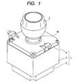
- Fig. 1 is a perspective view of a tilting operation type input device according to the embodiment of the invention
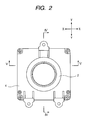
- Fig. 2 is a plan view of the tilting operation type input device
- Fig. 3 is a front view of the tilting operation type input device
- Fig. 4 is a sectional view taken along line IV-IV of Fig. 2
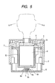
- Fig. 5 is a sectional view taken along line V-V of Fig. 2
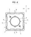
- Fig. 6 is a sectional view taken along line VI-VI of Fig. 3
- Fig. 7 is a perspective view of an operating body and a base that are provided in the tilting operation type input device.
- the tilting operation type input device is used as a control unit that intensively controls vehicle-mounted electrical apparatuses, such as an air-conditioner, a sound apparatus, and a navigation system, using one unit, and includes a housing 1 attached to a center console, etc. in a vehicle, and an operating knob 2 that projects from the housing 1.
- the housing 1 is composed of a case 3 having a hollow structure with upper and lower openings, a cover 4 that closes an upper open end of the case 3, and a base 5 that closes a lower open end of the case 3, all of which are formed of synthetic resin.
- a cylindrical holder 6 whose top surface is blocked is arranged inside the case 3, and an upper end of the holder 6 is integrally formed with a flange 7 having a quadrangular shape in plan view.
- a driver 8 is arranged inside the holder 6, and the holder 6 and the driver 8 are integrated by means of a plurality of concavo-convex engaging parts (refer to Fig. 6).
- the driver 8 projects upward through a through-hole 4a of the cover 4, and the driver 8 and the operating knob 2 arranged on the cover 4 are connected together. That is, the operating knob 2, the driver 7, and the holder 6 constitute an operating body that is tiltably operated by an operator (user).
- the operating knob 2 is adapted to be able to perform a rotational operation and make a push operation as well as a tilting operation, and a detection mechanism that detects the rotational operation or push operation of the operating knob 2 is housed inside the driver 8.
- a tilting projection 6a is integrally formed in the center of the lower surface of the holder 6, and a supporting protrusion 5b having a mortar-like recess 5a is integrally formed in the center of the top surface of the base 5.
- a plurality of guide grooves 3a are formed in four internal wall surfaces of the case 3, and if the X-Y orthogonal coordinates with the center of the holder 6 as an origin are set, each of the guide grooves 3a has extends in the X-direction or Y-direction. Meanwhile, a plurality of guide projections 7a are formed in four external wall surfaces of the flange 7 integrated with the upper end of the holder 6, and each of the guide projections 7a projects in the X-direction or Y-direction so that it can move within each corresponding guide groove 3a.
- the guide grooves 3a and the guide projections 7a constitute a guide mechanism, and the operating body (the operating knob 2, the driver 7, and the holder 6) that is tiltably supported on the base 5 is guided in the X-Y directions, which are orthogonal to each other, by the guide mechanism.
- a pair of driving rods 9 are held by the flange 7 of the holder 6, and the driving rods 9 are brought into pressure contact with a cam member (not shown) of an internal bottom surface of the cover 4 by the resilient force of a spring (not shown) so that the holder 6 may automatically return to its neutral position in a non-operating state of the operating body.
- a tilting detecting means 10 composed of a pair of sliders, photosensors (both of them are not shown), etc. is arranged between the flange 7 of the holder 6, and the cover 4, and the tilting operation of the operating body in the X-direction and Y-direction is detected by the tilting detecting means 10.
- a pair of regulating grooves 5c is formed in the top surface of the base 5 in positions that face each other by 180 degrees with the supporting protrusion 5b therebetween, and the regulating grooves 5c are arranged on a straight line L that extends in the Y-direction through the tilting fulcrum P.
- One regulating groove 5c is composed of a pair of rising walls 5d that is formed so as to project from the top surface of the base 5, and the other regulating groove 5c is also composed of a pair of rising walls 5d that is formed so as to project from top surface of the base 5.
- a pair of cylindrical projections 6b is formed so as to project from the bottom surface of the holder 6 in positions that face each other 180 degrees apart with the tilting projection 6a therebetween, and the cylindrical projections 6b are inserted into the corresponding regulating grooves 5c, respectively.
- the diameter of each of the cylindrical projections 6b, and the width (distance between both the rising walls 5d) of each of the regulating grooves 5c are set to be approximately equal to each other, and as shown in Fig. 5, an outer peripheral surface of the cylindrical projection 6b is sandwiched between both the rising walls 5d of the regulating groove 5c.
- an escape space S is secured between the bottom of the regulating groove 5c, and the cylindrical projection 6b, and this escape space S permits movement of the cylindrical projection 6b within the regulating groove 5c.
- FIGs. 1 to 5 show a non-operating state where any external force is not applied to the operating knob 2 at all.
- the operating knob 2, the driver 7, and the holder 6 that are components of the operating body are directed to the vertical direction.
- the outer peripheral surface of each of the cylindrical projections 6b formed so as to project from the bottom surface of the holder 6 is sandwiched between both the rising walls 5d of the each of the regulating grooves 5c formed in the top surface of the base 5, movement of the holder 6 around the vertical axis is regulated by the cylindrical projections 6b and the regulating grooves 5c, and rattling around the vertical axis is not generated in the operating body including the holder 6.
- the holder 6 tilts in the same direction with the tilting fulcrum P on the base 5 as a fulcrum, and with the tilting of the holder, the guide projections 7a of the flange 7 move within the corresponding guide grooves 3a of the case 3, and thereby the operating body is guided in the X-direction or Y-direction. Further, as the driver 8 moves in the same direction in conjunction with the tilting operation of the operating knob 2 in this way, the tilting operation of the operating body in the X-direction and Y-direction is detected by the tilting detecting means 10.
- the regulating grooves 5c that extend in the Y-direction through the tilting fulcrum P are formed in the top surface of the base 5, and the cylindrical projections 6b sandwiched between both the rising walls 5d of the regulating grooves 5c are formed so as to project from bottom surface of the holder 6.
- the cylindrical projections 6b rotate within the corresponding regulating grooves 5c, with the straight line L connecting the tilting fulcrum P with the regulating grooves 5c as a rotational axis, and when tilting operation of the operating knob 2 in the Y-direction is performed, the cylindrical projections 6b rotate within the regulating grooves 5c about the tilting fulcrum P. Accordingly, while the tilting operation of the operating body in the X-direction and Y-direction is permitted, rattling of the operating body around the vertical axis can be prevented.
- the configuration of the guide mechanism can be simplified.
- the two pairs of regulating grooves 5c and cylindrical projections 6b may be formed in the X-direction, and may be formed in the X-direction and Y-direction, respectively.
- the regulating grooves 5c are formed in the top surface of the base 5, and the cylindrical projections 6b are formed in the bottom surface of the holder 6
- the relationship between the regulating grooves and the cylindrical projections may be reversed such that the cylindrical projections are formed in the top surface of the base 5, and the regulating grooves are formed in the bottom surface of the holder 6.
Landscapes
- Physics & Mathematics (AREA)
- General Physics & Mathematics (AREA)
- Engineering & Computer Science (AREA)
- Automation & Control Theory (AREA)
- Switches With Compound Operations (AREA)
Abstract
Description
- The present invention relates to a tilting operation type input device that performs tilting operation of an operating body selectively in X-Y directions orthogonal to each other, thereby performing input.
- Conventionally, a tilting operation type input device in which an operating body is tiltably supported on an internal bottom surface of a housing with a hollow structure, a guide mechanism that guides the operating body in X-Y directions orthogonal to each other is attached to the housing, and when a user performs tilting operation of the operating body selectively in the X-direction and Y-direction, the tilting is detected by a detecting means, such as a switch, is known (for example, refer to
JP-A-2005-346645 - In the tilting operation type input device roughly configured as described above, when a pressing force in the direction of a plane acts on the upper slider along with tilting operation of the operating body, the lower slider slides in the X-direction along the guide grooves of the housing while being engaged with the upper slider, so that the operating body can be smoothly guided in the X-direction, and the upper slider slides in the Y-direction along the guide projections of the top surface of the lower slider, so that the operating body can be smoothly guided in the Y-direction. That is, since the guide mechanism interposed between the operating body and the housing is provided with a pair of upper and lower sliders that are movable orthogonal to each other, and both the sliders are assembled to the housing using the guide grooves or guide projections, the operating body can be smoothly guided in the X-Y directions at the time of tilting operation.
- Meanwhile, in the aforementioned conventional tilting operation type input device, the guide mechanism is arranged in an upper position of the housing that is apart in the vertical direction from a tilting fulcrum of the operating body, and the engaging grooves of the upper slider that is a constructional member of the guide mechanism, and the engaging projections of the operating body are engaged with each other, so that movement of the operating body in the tilting direction can be transmitted to parallel displacement of the upper slider. Thus, if the width of the engaging projections is not set to be smaller than the width of the engaging grooves, there is a possibility that the engaging projections may not freely move into the engaging grooves. In particular, the guide mechanism is composed of the upper slider and lower slider that are combined together so as to be movable in the directions orthogonal to each other. Therefore, if the dimension error, assembly error, etc. of the respective members including the housing and both the sliders are taken into consideration, it is necessary to secure comparatively large clearance along a circumferential direction between the engaging projections and the engaging grooves. As a result, when a user tries to perform tilting operation of the operating body, there is a problem in that the operating body may be minutely rotated and rattled around the rotational axis within the above clearance, and the quality of an operational feeling may be degraded.
- The invention has been made in consideration of such conventional circumstances. It is therefore the object of the invention to provide a tilting operation type input device that can prevent rattling of an operating body around a vertical axis with a simple configuration.
- In order to achieve the above object, a tilting operation type input device according to an aspect of the invention includes a base; an operating body that is tiltably supported about a tilting fulcrum on the base; a guide mechanism that guides the operating body in X-Y directions orthogonal to each other; and a detecting means that detects tilting of the operating body in the X-Y directions. Here, a regulating groove that extends in at least one direction of the X-Y directions from the tilting fulcrum is formed in any one of a bottom surface of the operating body and a top surface of the base that faces the bottom surface, and a projection that is sandwiched between internal wall surfaces of the regulating groove that face each other is formed in the other of the bottom surface and the top surface. When tilting operation of the operating body in any one direction of the X-Y directions is performed, the projection rotates within the regulating groove about the tilting fulcrum, and when tilting operation of the operating body in the other direction of the X-Y direction is performed, the projection rotates within the regulating groove with a straight line connecting the tilting fulcrum with the regulating groove as a rotational axis.
- In the tilting operation type input device configured in this way, when tilting operation of the operating body in any one direction of the X-Y directions is performed, the projection freely rotates within the regulating groove about the tilting fulcrum, and when tilting operation of the operating body in the other direction of the X-Y directions is performed, the projection rotates with a straight line connecting the tilting fulcrum with the regulating groove as a rotational axis. Therefore, while tilting operation of the operating body is permitted, chattering around the vertical axis can be prevented.
- In the above configuration, it is also possible to use as the projection what a plurality of spherical bodies are arranged in one row. However, it is preferable that the projection is composed of a cylindrical projection that extends in at least one direction of the X-Y directions from the tilting fulcrum, and both the internal wall surfaces of the regulating groove face each other at a distance approximately equal to the diameter of the cylindrical projection. This is because the projection can be formed in a simple shape, which is preferable. In this case, although the cylindrical projection may be formed on the top surface of the base and the regulating groove may be formed in the bottom surface of the operating body, it is preferable that the cylindrical projection is formed so as to project from the bottom surface of the operating body, and the regulating groove is composed of a pair of rising walls formed so as to project from the top surface of the base.
- Further, in the above configuration, the configuration of the guide mechanism that guides the operating body in the X-Y directions is not particularly limited. However, it is preferable that the guide mechanism are composed of a plurality of guide grooves formed in an internal wall surface of a case extending upward from the base so as to surround the operating body, and a plurality of guide projections formed so as to project from a top external wall surface of the operating body, and the guide projections move within the corresponding guide grooves at the time of tilting operation of the operating body. This is because the operating body can be guided in the X-Y directions using the guide mechanism with a simple configuration.
- According to the tilting operation type input device of the invention, the projection provided formed in one of the bottom surface of the operating body and the top surface of the base is sandwiched between mutually facing internal wall surfaces of the regulating groove formed in the other. Also, when tilting operation of the operating body in any one direction of the X-Y directions is performed, the projection freely rotates within the regulating groove about the tilting fulcrum, and when tilting operation of the operating body in the other direction of the X-Y directions is performed, the projection rotates with a straight line connecting the tilting fulcrum with the regulating groove as a rotational axis. Therefore, while tilting operation of the operating body is permitted, chattering around the vertical axis can be prevented.
-
- Fig. 1 is a perspective view of a tilting operation type input device according to an embodiment of the invention;
- Fig. 2 is a plan view of the tilting operation type input device;
- Fig. 3 is a front view of the tilting operation type input device;
- Fig. 4 is a sectional view taken along line IV-IV of Fig. 2;
- Fig. 5 is a sectional view taken along line V-V of Fig. 2;
- Fig. 6 is a sectional view taken along line VI-VI of Fig. 3; and
- Fig. 7 is a perspective view of an operating body and base that are provided in the tilting operation type input device.
- An embodiment of an invention will be described with reference to the accompanying drawings in which Fig. 1 is a perspective view of a tilting operation type input device according to the embodiment of the invention, Fig. 2 is a plan view of the tilting operation type input device, Fig. 3 is a front view of the tilting operation type input device, Fig. 4 is a sectional view taken along line IV-IV of Fig. 2, Fig. 5 is a sectional view taken along line V-V of Fig. 2, Fig. 6 is a sectional view taken along line VI-VI of Fig. 3, and Fig. 7 is a perspective view of an operating body and a base that are provided in the tilting operation type input device.
- The tilting operation type input device according to the present embodiment is used as a control unit that intensively controls vehicle-mounted electrical apparatuses, such as an air-conditioner, a sound apparatus, and a navigation system, using one unit, and includes a
housing 1 attached to a center console, etc. in a vehicle, and anoperating knob 2 that projects from thehousing 1. Thehousing 1 is composed of acase 3 having a hollow structure with upper and lower openings, acover 4 that closes an upper open end of thecase 3, and abase 5 that closes a lower open end of thecase 3, all of which are formed of synthetic resin. - A
cylindrical holder 6 whose top surface is blocked is arranged inside thecase 3, and an upper end of theholder 6 is integrally formed with aflange 7 having a quadrangular shape in plan view. Adriver 8 is arranged inside theholder 6, and theholder 6 and thedriver 8 are integrated by means of a plurality of concavo-convex engaging parts (refer to Fig. 6). Thedriver 8 projects upward through a through-hole 4a of thecover 4, and thedriver 8 and theoperating knob 2 arranged on thecover 4 are connected together. That is, theoperating knob 2, thedriver 7, and theholder 6 constitute an operating body that is tiltably operated by an operator (user). In addition, although not shown, theoperating knob 2 is adapted to be able to perform a rotational operation and make a push operation as well as a tilting operation, and a detection mechanism that detects the rotational operation or push operation of theoperating knob 2 is housed inside thedriver 8. - As shown in Figs. 4 and 7, a
tilting projection 6a is integrally formed in the center of the lower surface of theholder 6, and a supportingprotrusion 5b having a mortar-like recess 5a is integrally formed in the center of the top surface of thebase 5. By inserting thetilting projection 6a into therecess 5a of the supportingprotrusion 5b, theholder 6 is tiltably supported on thebase 5 with an engaging part between thetilting projection 6a and therecess 5a as a tilting fulcrum P. As shown in Fig. 6, a plurality ofguide grooves 3a are formed in four internal wall surfaces of thecase 3, and if the X-Y orthogonal coordinates with the center of theholder 6 as an origin are set, each of theguide grooves 3a has extends in the X-direction or Y-direction. Meanwhile, a plurality ofguide projections 7a are formed in four external wall surfaces of theflange 7 integrated with the upper end of theholder 6, and each of theguide projections 7a projects in the X-direction or Y-direction so that it can move within eachcorresponding guide groove 3a. Theguide grooves 3a and theguide projections 7a constitute a guide mechanism, and the operating body (theoperating knob 2, thedriver 7, and the holder 6) that is tiltably supported on thebase 5 is guided in the X-Y directions, which are orthogonal to each other, by the guide mechanism. In addition, a pair ofdriving rods 9 are held by theflange 7 of theholder 6, and thedriving rods 9 are brought into pressure contact with a cam member (not shown) of an internal bottom surface of thecover 4 by the resilient force of a spring (not shown) so that theholder 6 may automatically return to its neutral position in a non-operating state of the operating body. Further, a tilting detecting means 10 composed of a pair of sliders, photosensors (both of them are not shown), etc. is arranged between theflange 7 of theholder 6, and thecover 4, and the tilting operation of the operating body in the X-direction and Y-direction is detected by the tilting detecting means 10. - Referring back to Figs. 4 and 7, a pair of regulating
grooves 5c is formed in the top surface of thebase 5 in positions that face each other by 180 degrees with the supportingprotrusion 5b therebetween, and the regulatinggrooves 5c are arranged on a straight line L that extends in the Y-direction through the tilting fulcrum P. One regulatinggroove 5c is composed of a pair of risingwalls 5d that is formed so as to project from the top surface of thebase 5, and the other regulatinggroove 5c is also composed of a pair of risingwalls 5d that is formed so as to project from top surface of thebase 5. Further, a pair ofcylindrical projections 6b is formed so as to project from the bottom surface of theholder 6 in positions that face each other 180 degrees apart with thetilting projection 6a therebetween, and thecylindrical projections 6b are inserted into the correspondingregulating grooves 5c, respectively. Here, the diameter of each of thecylindrical projections 6b, and the width (distance between both the risingwalls 5d) of each of the regulatinggrooves 5c are set to be approximately equal to each other, and as shown in Fig. 5, an outer peripheral surface of thecylindrical projection 6b is sandwiched between both the risingwalls 5d of the regulatinggroove 5c. Further, as shown in Fig. 6, an escape space S is secured between the bottom of the regulatinggroove 5c, and thecylindrical projection 6b, and this escape space S permits movement of thecylindrical projection 6b within the regulatinggroove 5c. - In the tilting operation type input device constructed in this way, Figs. 1 to 5 show a non-operating state where any external force is not applied to the
operating knob 2 at all. In this state, theoperating knob 2, thedriver 7, and theholder 6 that are components of the operating body are directed to the vertical direction. At this time, since the outer peripheral surface of each of thecylindrical projections 6b formed so as to project from the bottom surface of theholder 6 is sandwiched between both the risingwalls 5d of the each of the regulatinggrooves 5c formed in the top surface of thebase 5, movement of theholder 6 around the vertical axis is regulated by thecylindrical projections 6b and the regulatinggrooves 5c, and rattling around the vertical axis is not generated in the operating body including theholder 6. - If an operator performs tilting operation of the operating
knob 2 in the X-direction or Y-direction from such a non-operating state, theholder 6 tilts in the same direction with the tilting fulcrum P on thebase 5 as a fulcrum, and with the tilting of the holder, theguide projections 7a of theflange 7 move within thecorresponding guide grooves 3a of thecase 3, and thereby the operating body is guided in the X-direction or Y-direction. Further, as thedriver 8 moves in the same direction in conjunction with the tilting operation of the operatingknob 2 in this way, the tilting operation of the operating body in the X-direction and Y-direction is detected by thetilting detecting means 10. In this case, as shown in Fig. 5, when an operator performs tilting operation of the operatingknob 2 in the X-direction, thecylindrical projections 6b rotate within the regulatinggrooves 5c with the straight line L as a rotational axis. Therefore, tilting operation of the operating body in the X-direction can be performed smoothly. Meanwhile, as shown in Fig. 4, when an operator performs tilting operation of the operatingknob 2 in the Y-direction, thecylindrical projections 6b rotate within the escape spaces S of the regulatinggrooves 5c about the tilting fulcrum P. Therefore, tilting operation of the operating body in the Y-direction can be performed smoothly. Accordingly, while the tilting operation of the operating body (the operatingknob 2, thedriver 7, and the holder 6) in the X-direction and Y-direction is permitted, chattering of the operating body around the vertical axis can be prevented, and the quality of an operational feeling improves remarkably. - As such, in the tilting operation type input device in the present embodiment, the regulating
grooves 5c that extend in the Y-direction through the tilting fulcrum P are formed in the top surface of thebase 5, and thecylindrical projections 6b sandwiched between both the risingwalls 5d of the regulatinggrooves 5c are formed so as to project from bottom surface of theholder 6. Thus, when tilting operation of the operatingknob 2 in the X-direction is performed, thecylindrical projections 6b rotate within the corresponding regulatinggrooves 5c, with the straight line L connecting the tilting fulcrum P with the regulatinggrooves 5c as a rotational axis, and when tilting operation of the operatingknob 2 in the Y-direction is performed, thecylindrical projections 6b rotate within the regulatinggrooves 5c about the tilting fulcrum P. Accordingly, while the tilting operation of the operating body in the X-direction and Y-direction is permitted, rattling of the operating body around the vertical axis can be prevented. Further, since the plurality ofguide grooves 3a formed in the internal wall surface of thecase 3 integrated with thebase 5, and the plurality ofguide projections 7a formed so as to project from the external wall surface of theflange 7 of theholder 6 constitute a guide mechanism, and this guide mechanism guides the operating body in the X-direction and Y-direction, the configuration of the guide mechanism can be simplified. - In addition, although the case where two pairs of the regulating
grooves 5c andcylindrical projections 6b are formed on the straight line L that extends in the Y-direction through the tilting fulcrum P has been described in the above embodiment, the two pairs of regulatinggrooves 5c andcylindrical projections 6b may be formed in the X-direction, and may be formed in the X-direction and Y-direction, respectively. Further, although the case where the regulatinggrooves 5c are formed in the top surface of thebase 5, and thecylindrical projections 6b are formed in the bottom surface of theholder 6 has been described in the above embodiment, the relationship between the regulating grooves and the cylindrical projections may be reversed such that the cylindrical projections are formed in the top surface of thebase 5, and the regulating grooves are formed in the bottom surface of theholder 6.
Claims (4)
- A tilting operation type input device including a base (5), an operating body (6) that is tiltably supported about a tilting fulcrum on the base (5), a guide mechanism (3a, 7a) that guides the operating body (6) in X-Y directions orthogonal to each other, and a detecting means that detects tilting of the operating body (6) in the X-Y directions, characterized in that
a regulating groove (5c) that extends in at least one direction of the X-Y directions from the tilting fulcrum (P) is formed in any one of a bottom surface of the operating body (6) and a top surface of the base (5) that faces the bottom surface,//and a projection (6b) that is sandwiched between internal wall surfaces of the regulating groove (5c) that face each other is formed in the other of the bottom surface and the top surface, and
when tilting operation of the operating body (6) in any one direction of the X-Y directions is performed, the projection (6b) rotates within the regulating groove (5c) about the tilting fulcrum (P), and when tilting operation of the operating body (6) in the other direction of the X-Y direction is performed, the projection (6b) rotates within the regulating groove (5c) with a straight line (L) connecting the tilting fulcrum (P) with the regulating groove (5c) as a rotational axis. - The tilting operation type input device according to Claim 1,
wherein the projection (6b) is composed of a cylindrical projection (6b) that extends in at least one direction of the X-Y directions from the tilting fulcrum (P), and both the internal wall surfaces of the regulating groove (5c) face each other at a distance approximately equal to the diameter of the cylindrical projection (6b). - The tilting operation type input device according to Claim 2,
wherein the cylindrical projection (6b) is formed so as to project from bottom surface of the operating body (6), and the regulating groove (5c) is composed of a pair of rising walls (5d) formed so as to project from the top surface of the base (5). - The tilting operation type input device according to any one of Claims 1 to 3,
wherein the guide mechanism (3a, 7a) are composed of a plurality of guide grooves (3a) formed in an internal wall surface of a case (3) extending upward from the base (5) so as to surround the operating body (6), and a plurality of guide projections (7a) formed so as to project from a top external wall surface of the operating body (6), and the guide projections (7a) move within the corresponding guide grooves (3a) at the time of tilting operation of the operating body (6).
Applications Claiming Priority (1)
| Application Number | Priority Date | Filing Date | Title |
|---|---|---|---|
| JP2006211044A JP2008041317A (en) | 2006-08-02 | 2006-08-02 | Rocking operation type input device |
Publications (1)
| Publication Number | Publication Date |
|---|---|
| EP1884858A1 true EP1884858A1 (en) | 2008-02-06 |
Family
ID=38596263
Family Applications (1)
| Application Number | Title | Priority Date | Filing Date |
|---|---|---|---|
| EP07014610A Withdrawn EP1884858A1 (en) | 2006-08-02 | 2007-07-25 | Tilting operation type input device |
Country Status (2)
| Country | Link |
|---|---|
| EP (1) | EP1884858A1 (en) |
| JP (1) | JP2008041317A (en) |
Cited By (3)
| Publication number | Priority date | Publication date | Assignee | Title |
|---|---|---|---|---|
| US8919218B2 (en) | 2011-12-09 | 2014-12-30 | Hyundai Motor Company | Transmission system for shift by wire |
| US9140354B2 (en) | 2011-11-28 | 2015-09-22 | Hyundai Motor Company | Shift/tilt locking apparatus and method for shift lever of automatic transmission |
| WO2021001099A1 (en) * | 2019-07-01 | 2021-01-07 | Agco International Gmbh | Joystick |
Citations (5)
| Publication number | Priority date | Publication date | Assignee | Title |
|---|---|---|---|---|
| DE3930754C1 (en) * | 1989-09-14 | 1991-04-11 | Leopold Kostal Gmbh & Co Kg, 5880 Luedenscheid, De | Electrical four-way switch - has joystick moving block operating leaf springs of snap-action switches |
| US6059660A (en) * | 1997-01-30 | 2000-05-09 | Yazaki Corporation | Joystick type multifunctional controller |
| US20030099023A1 (en) * | 2001-11-28 | 2003-05-29 | Orrico Mario M. | Optical joystick module |
| EP1584365A1 (en) * | 2003-01-17 | 2005-10-12 | Nikko Co., Ltd. | Transmitter for wireless control |
| WO2006016138A1 (en) * | 2004-08-09 | 2006-02-16 | Peratech Limited | Full-axis sensor for detecting input force and torque |
-
2006
- 2006-08-02 JP JP2006211044A patent/JP2008041317A/en not_active Withdrawn
-
2007
- 2007-07-25 EP EP07014610A patent/EP1884858A1/en not_active Withdrawn
Patent Citations (5)
| Publication number | Priority date | Publication date | Assignee | Title |
|---|---|---|---|---|
| DE3930754C1 (en) * | 1989-09-14 | 1991-04-11 | Leopold Kostal Gmbh & Co Kg, 5880 Luedenscheid, De | Electrical four-way switch - has joystick moving block operating leaf springs of snap-action switches |
| US6059660A (en) * | 1997-01-30 | 2000-05-09 | Yazaki Corporation | Joystick type multifunctional controller |
| US20030099023A1 (en) * | 2001-11-28 | 2003-05-29 | Orrico Mario M. | Optical joystick module |
| EP1584365A1 (en) * | 2003-01-17 | 2005-10-12 | Nikko Co., Ltd. | Transmitter for wireless control |
| WO2006016138A1 (en) * | 2004-08-09 | 2006-02-16 | Peratech Limited | Full-axis sensor for detecting input force and torque |
Cited By (5)
| Publication number | Priority date | Publication date | Assignee | Title |
|---|---|---|---|---|
| US9140354B2 (en) | 2011-11-28 | 2015-09-22 | Hyundai Motor Company | Shift/tilt locking apparatus and method for shift lever of automatic transmission |
| US9618110B2 (en) | 2011-11-28 | 2017-04-11 | Hyundai Motor Company | Shift/tilt locking apparatus and method for shift lever of automatic transmission |
| US8919218B2 (en) | 2011-12-09 | 2014-12-30 | Hyundai Motor Company | Transmission system for shift by wire |
| WO2021001099A1 (en) * | 2019-07-01 | 2021-01-07 | Agco International Gmbh | Joystick |
| US11874686B2 (en) | 2019-07-01 | 2024-01-16 | Agco International Gmbh | Joystick |
Also Published As
| Publication number | Publication date |
|---|---|
| JP2008041317A (en) | 2008-02-21 |
Similar Documents
| Publication | Publication Date | Title |
|---|---|---|
| US8186240B2 (en) | Joystick type switch device | |
| KR101149805B1 (en) | Multidirectional input device | |
| US8921719B2 (en) | Multi-directional switch device | |
| JP5956917B2 (en) | Multi-directional input device | |
| KR101096925B1 (en) | Integrated switching unit with directional switch and apparatus with the same | |
| US10626914B2 (en) | Spherical bearing device and switch | |
| JP2009004140A (en) | Multidirectional operation component | |
| KR20120109393A (en) | Operation input device | |
| KR101317563B1 (en) | Operation input device | |
| JP2017168305A (en) | Multi-directional input device | |
| KR20120109394A (en) | Operation input device | |
| JP7125557B2 (en) | Operating device | |
| KR101351107B1 (en) | Operation input device | |
| JP2019123432A (en) | Shift device | |
| US20120260762A1 (en) | Operation input device | |
| JP2022137925A (en) | switch device | |
| JP2008041317A (en) | Rocking operation type input device | |
| EP1708219A1 (en) | Multidirectional input device | |
| JP2007207772A (en) | Multi-directional input device | |
| JP2007257852A (en) | Jog switch structure having rotation volume | |
| JP2006286334A (en) | Multiple direction input device | |
| JP7620375B2 (en) | Input Devices | |
| JP5493620B2 (en) | In-vehicle device operation device | |
| WO2008044419A1 (en) | Operation device | |
| JP4846662B2 (en) | Multi-directional operation switch |
Legal Events
| Date | Code | Title | Description |
|---|---|---|---|
| PUAI | Public reference made under article 153(3) epc to a published international application that has entered the european phase |
Free format text: ORIGINAL CODE: 0009012 |
|
| AK | Designated contracting states |
Kind code of ref document: A1 Designated state(s): AT BE BG CH CY CZ DE DK EE ES FI FR GB GR HU IE IS IT LI LT LU LV MC MT NL PL PT RO SE SI SK TR |
|
| AX | Request for extension of the european patent |
Extension state: AL BA HR MK YU |
|
| 17P | Request for examination filed |
Effective date: 20080125 |
|
| AKX | Designation fees paid |
Designated state(s): DE FR GB |
|
| 17Q | First examination report despatched |
Effective date: 20081010 |
|
| STAA | Information on the status of an ep patent application or granted ep patent |
Free format text: STATUS: THE APPLICATION HAS BEEN WITHDRAWN |
|
| 18W | Application withdrawn |
Effective date: 20100127 |