EP1884691A1 - Lip type seal - Google Patents
Lip type seal Download PDFInfo
- Publication number
- EP1884691A1 EP1884691A1 EP06756361A EP06756361A EP1884691A1 EP 1884691 A1 EP1884691 A1 EP 1884691A1 EP 06756361 A EP06756361 A EP 06756361A EP 06756361 A EP06756361 A EP 06756361A EP 1884691 A1 EP1884691 A1 EP 1884691A1
- Authority
- EP
- European Patent Office
- Prior art keywords
- lip
- lips
- type seal
- lip type
- flat surfaces
- Prior art date
- Legal status (The legal status is an assumption and is not a legal conclusion. Google has not performed a legal analysis and makes no representation as to the accuracy of the status listed.)
- Withdrawn
Links
- 239000011347 resin Substances 0.000 claims abstract description 12
- 229920005989 resin Polymers 0.000 claims abstract description 12
- 230000013011 mating Effects 0.000 abstract 1
- 238000007789 sealing Methods 0.000 description 13
- 239000004810 polytetrafluoroethylene Substances 0.000 description 5
- 229920001343 polytetrafluoroethylene Polymers 0.000 description 5
- 239000007788 liquid Substances 0.000 description 4
- 230000000694 effects Effects 0.000 description 3
- 239000000463 material Substances 0.000 description 3
- 238000003825 pressing Methods 0.000 description 3
- 230000006835 compression Effects 0.000 description 2
- 238000007906 compression Methods 0.000 description 2
- 239000000446 fuel Substances 0.000 description 2
- 239000004519 grease Substances 0.000 description 2
- 238000002347 injection Methods 0.000 description 2
- 239000007924 injection Substances 0.000 description 2
- 230000002093 peripheral effect Effects 0.000 description 2
- 230000002706 hydrostatic effect Effects 0.000 description 1
- 238000000034 method Methods 0.000 description 1
Images


Classifications
-
- F—MECHANICAL ENGINEERING; LIGHTING; HEATING; WEAPONS; BLASTING
- F16—ENGINEERING ELEMENTS AND UNITS; GENERAL MEASURES FOR PRODUCING AND MAINTAINING EFFECTIVE FUNCTIONING OF MACHINES OR INSTALLATIONS; THERMAL INSULATION IN GENERAL
- F16J—PISTONS; CYLINDERS; SEALINGS
- F16J15/00—Sealings
- F16J15/16—Sealings between relatively-moving surfaces
- F16J15/32—Sealings between relatively-moving surfaces with elastic sealings, e.g. O-rings
-
- F—MECHANICAL ENGINEERING; LIGHTING; HEATING; WEAPONS; BLASTING
- F16—ENGINEERING ELEMENTS AND UNITS; GENERAL MEASURES FOR PRODUCING AND MAINTAINING EFFECTIVE FUNCTIONING OF MACHINES OR INSTALLATIONS; THERMAL INSULATION IN GENERAL
- F16J—PISTONS; CYLINDERS; SEALINGS
- F16J15/00—Sealings
- F16J15/16—Sealings between relatively-moving surfaces
- F16J15/32—Sealings between relatively-moving surfaces with elastic sealings, e.g. O-rings
- F16J15/3204—Sealings between relatively-moving surfaces with elastic sealings, e.g. O-rings with at least one lip
- F16J15/3208—Sealings between relatively-moving surfaces with elastic sealings, e.g. O-rings with at least one lip provided with tension elements, e.g. elastic rings
- F16J15/3212—Sealings between relatively-moving surfaces with elastic sealings, e.g. O-rings with at least one lip provided with tension elements, e.g. elastic rings with metal springs
-
- F—MECHANICAL ENGINEERING; LIGHTING; HEATING; WEAPONS; BLASTING
- F16—ENGINEERING ELEMENTS AND UNITS; GENERAL MEASURES FOR PRODUCING AND MAINTAINING EFFECTIVE FUNCTIONING OF MACHINES OR INSTALLATIONS; THERMAL INSULATION IN GENERAL
- F16J—PISTONS; CYLINDERS; SEALINGS
- F16J15/00—Sealings
- F16J15/16—Sealings between relatively-moving surfaces
- F16J15/32—Sealings between relatively-moving surfaces with elastic sealings, e.g. O-rings
- F16J15/3204—Sealings between relatively-moving surfaces with elastic sealings, e.g. O-rings with at least one lip
- F16J15/3232—Sealings between relatively-moving surfaces with elastic sealings, e.g. O-rings with at least one lip having two or more lips
- F16J15/3236—Sealings between relatively-moving surfaces with elastic sealings, e.g. O-rings with at least one lip having two or more lips with at least one lip for each surface, e.g. U-cup packings
Definitions
- the present invention relates to a lip type seal for reciprocation, which is made of a resin such as PTFE.
- This lip type seal is used for a fuel injection pump for a gasoline direct injection engine as a seal for a high pressure fuel pump and used in a hydraulic, pneumatic, or hydrostatic apparatus.
- sealing property is largely influenced by a shape of a tip part of a lip.
- a shape of a tip part of a lip is molded by a material in which creep easily advances, e.g., PTFE resin
- a cross section shape of a tip part of a lip is changed with elapse of time by compression force of a sliding on a shaft so as to change a sealing property.
- PTFE resin a material in which creep easily advances
- a cross section shape of a tip part of a lip is changed with elapse of time by compression force of a sliding on a shaft so as to change a sealing property.
- a lip type seal 101 using a resin material such as PTFE is installed between a housing 110 and a shaft 111 as illustrated in FIG. 5, the lip type seal 101 is conventionally processed so as to have a round shape 104 or to have a sharp shape 105 illustrated in Fig. 6 (1) and Fig. 6 (2) respectively, which are expanded cross sectional views to illustrate shapes of a tip part 103 of a lip 102 encircled by a circle of a broken line.
- a reciprocating seal for a shaft 111 which reciprocates, differently from a rotating seal, different stresses occur on the forward route and the backward route at the tip part 103 of the lip 102 contacting to the shaft 111, and the shape of the tip part 103 of the lip 102 becomes hardly uniform due to creep. Therefore, there is a problem that the round shape 104 and sharp shape 105 are more easily deformed after use than a case of the rotating seal, and thus a sealing property is changed.
- a shape of the tip part 103 of the lip 102 is processed to have the round shape 104 is to obtain wear resistance by keeping an oil film on a sliding face.
- sealing property is somewhat inferior.
- the shape of the tip part 103 is processed to have the sharp shape 105 so as to reduce a leaking amount, a sealing property can be kept, but wear resistance is somewhat inferior.
- patent documents disclose a technique to form an annular flat surface at a tip part of a seal lip of an oil seal with a predetermined axial width to fit the flat surface slidably to a matching member. However, they do disclose nothing about a resin lip type seal.
- the present invention solves the above-described problems, and an objective of the present invention is to provide a resin lip type seal installed in an annular clearance between a fixing member housing and a reciprocating operation member and capable of preventing shapes of tip parts fitted to a matching member from being changed with elapse of time.
- Another objective of the present invention is to provide shapes of tip parts of lips having both of function for securing low leak, which is the feature of a sharp shape, and function for securing oil film thickness, which is the feature of round shape, in a well balanced state.
- a resin lip type seal being installed in an annular clearance between a fixing member and a reciprocating operation member and including a hole part having an opening at one end, wherein flat surfaces with axial widths having edge parts are formed at tip parts of lips, and the flat surfaces fit to a matching member.
- a plate spring, a coil spring, or an O-ring at the hole part can be mounted inside the lip type seal.
- the axial widths of the flat surfaces are preferably determined to be 5 to 30% of the overall axial widths of the lips.
- the present invention has the following effects.
- the tip parts of the lips are formed to be flat surfaces, a contacting area is comparatively larger than the round shape or the sharp shape so as to reduce a surface pressure.
- a contacting area is comparatively larger than the round shape or the sharp shape so as to reduce a surface pressure.
- the flat surfaces formed at the tip parts of the lips have edge parts.
- the edge parts exercise a low leak function, which is the feature in the case that the conventional tip parts of the lips have the sharp shape
- the flat surfaces exercise a function for securing an oil film thickness, which is the feature in the case that the conventional tip parts of the lips have the round shape. Therefore, the tip parts can have shapes for securing the both features in a well-balanced state.
- the present invention can prevent change of the tip parts with elapse of time, also by means that a plate spring is mounted inside the hole part.
- a plate spring is mounted inside the hole part.
- the axial widths of the flat surfaces are determined to be 5 to 30% of the overall axial widths of the lips, it is more preferable to obtain the above-described effects.
- a lip type seal according to the present invention is not formed to make edge or line contact, but is formed to make face contact.
- sealing property is improved, so that the lip type seal is suitable to use not only for a high viscosity liquid such as grease but also for a low viscosity liquid such as gasoline.
- a lip type seal 1 As illustrated in FIG. 1, a lip type seal 1 according to embodiment 1 of the present invention is installed in an annular clearance between a housing and a reciprocating shaft inserted into the inner peripheral side of the housing, which are not illustrated.
- the lip type seal 1 includes a seal main body 2 and a plate spring 11.
- the seal main body 2 is integrally formed with PTFE resin.
- the seal main body 2 includes an outer diameter side lip 3 which fits to the housing and mainly seals gasoline existing at the right side in FIG. 1, an inner diameter side lip 4 which slidably fits to the shaft and mainly seals gasoline too, and a hole part 5 opening at the gasoline side (G).
- FIG. 2 illustrates an expanded state of a tip part 41 of an inner diameter side lip 4 encircled by a broken line in FIG. 1.
- the tip part 41 is formed to have a flat surface 21, which has flat and predetermined width in the axial direction, and edge parts 22 at end parts in the width direction.
- An axial width W of the flat surface 21 formed at the tip part 41 is determined to be 5 to 30% of an overall axial width A of the inner diameter side lip 4 illustrated in FIG. 1.
- a tip part 31 of an outer diameter side lip 3 also is formed to have a flat surface 21, which has predetermined width in the axial direction, and edge parts 22 at end parts in the width direction, and the axial width W of the flat surface 21 is determined to be 5 to 30% of the overall axial width A of the outer diameter side lip 3 as illustrated in FIG. 1, like the inner diameter side lip 4.
- a hole part 5 provided in the seal main body 2 having an opening at one end is provided inside with a plate spring 11 having a approximately U-shaped cross section so as to open toward the gasoline side (G).
- This plate spring 11 gives pressing force in the radial direction to the outer diameter side lip 3 and the inner diameter side lip 4.
- FIG. 3 illustrates the state in which the lip type seal 1 having the above-described structure is installed in an annular clearance between the housing 12 and the reciprocating shaft 13 inserted into the inner peripheral side of the housing 12.
- flat surface 21 formed at tip part 31 fits to the housing 12 which is a matching member.
- flat surface 21 formed at tip part 41 slidably fits to a shaft 13 which is a matching member.
- the flat surfaces 21 formed at the tip parts (31, 41) of the outer diameter side lip 3 and the inner diameter side lip 4 fit to the respective matching members .
- the change with elapse of time can be prevented, and designed sealing property at the time of initial use can be kept.
- the flat surfaces 21 formed at the tip parts (31, 41) of the outer diameter side lip 3 and the inner diameter side lip 4 have edge parts 22 at end parts in the axial direction.
- the edge parts 22 exercise a low leak function, which is the feature in the case of the conventional tip parts of the lips having a sharp shape
- the flat surfaces 21 exercise a function for securing an oil film thickness, which is the feature in the case of the conventional tip parts of the lips having a round shape. Therefore, tip parts of lips securing both of the low leak function and the function for securing an oil film thickness in a well-balanced state can be designed.
- the lip type seal 1 according to the present invention is not formed to make edge or line contact, but formed to make face contact by the flat surfaces 21.
- sealing property can be improved not only with respect to a high viscosity liquid such as grease but also with respect to a low viscosity liquid such as gasoline.
- the above-described embodiment discloses the case of the plate spring 11 being mounted inside the hole part 5.
- an elastic body such as a coil spring or an O-ring having the similar operational effects can be used instead of the plate spring 11.
- the lip type seal 1 exercises a self seal function by applying pressure and may be used without an elastic body such as a plate spring at the hole part 5.
- FIG. 4 is a cross sectional view of a lip type seal 1 according to embodiment 2 of the present invention .
- the lip type seal 1 integrally includes an oil lip 6 having an approximately rectangular cross section at the opposite side (G') to gasoline side, and the oil lip 6 slidably fits to the reciprocating shaft.
- a tip part 61 of the oil lip 6 is formed to have a flat surface 21 having edge parts 22 at end parts in the width direction, and the axial widths W of the flat surface 21 are determined to be 5 to 30% of the overall axial widths (A) of the oil lip 6, like the tip parts (31, 41) of the outer diameter side lip 3 and the inner diameter side lip 4.
Landscapes
- Engineering & Computer Science (AREA)
- General Engineering & Computer Science (AREA)
- Mechanical Engineering (AREA)
- Sealing With Elastic Sealing Lips (AREA)
- Sealing Devices (AREA)
Abstract
A resin lip type seal (1) installed in an annular clearance between a housing (12) and a reciprocating shaft (13) and capable of preventing the shapes of the tip parts (31, 41, 61) of lips (3, 4, 6) fitted to a mating member (12 or 13) from being changed with elapse of time. The shapes of the tip parts (31, 41, 61) of lips (3, 4, 6) are so determined that they comprise, in a well-balanced state, both a function for securing low leak which is the feature of sharp shape and a function for securing oil film thickness which is the feature of R-shape. Flat surfaces (21) with axial widths (W) having edge parts (22) are formed at the tip parts (31, 41, 61) of the lips (3, 4, 6). Also, the axial widths of the flat surfaces (21) are determined to be 5 to 30% of the overall axial widths (A) of the lips (3,4,6).
Description
- The present invention relates to a lip type seal for reciprocation, which is made of a resin such as PTFE. This lip type seal is used for a fuel injection pump for a gasoline direct injection engine as a seal for a high pressure fuel pump and used in a hydraulic, pneumatic, or hydrostatic apparatus.
- As for a lip type seal, sealing property is largely influenced by a shape of a tip part of a lip. When the lip type seal is molded by a material in which creep easily advances, e.g., PTFE resin, a cross section shape of a tip part of a lip is changed with elapse of time by compression force of a sliding on a shaft so as to change a sealing property. Thus, there is a problem that a stable sealing property cannot be obtained.
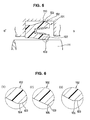
- In particular, when a
lip type seal 101 using a resin material such as PTFE is installed between ahousing 110 and ashaft 111 as illustrated in FIG. 5, thelip type seal 101 is conventionally processed so as to have around shape 104 or to have asharp shape 105 illustrated in Fig. 6 (1) and Fig. 6 (2) respectively, which are expanded cross sectional views to illustrate shapes of atip part 103 of alip 102 encircled by a circle of a broken line. However, when thetip part 103 of thelip 102 is processed to have theround shape 104 and thesharp shape 105, there is a problem that the shape of thetip part 103 fitted to thehousing 110 or theshaft 111, which is a matching member, becomes to be aflat state 106 by creeping after use as illustrated in FIG. 6 (3), and thus a sealing property is changed. - More particularly, a reciprocating seal for a
shaft 111 which reciprocates, differently from a rotating seal, different stresses occur on the forward route and the backward route at thetip part 103 of thelip 102 contacting to theshaft 111, and the shape of thetip part 103 of thelip 102 becomes hardly uniform due to creep. Therefore, there is a problem that theround shape 104 andsharp shape 105 are more easily deformed after use than a case of the rotating seal, and thus a sealing property is changed. - In addition, the reason why a shape of the
tip part 103 of thelip 102 is processed to have theround shape 104 is to obtain wear resistance by keeping an oil film on a sliding face. However, there is a problem that sealing property is somewhat inferior. When the shape of thetip part 103 is processed to have thesharp shape 105 so as to reduce a leaking amount, a sealing property can be kept, but wear resistance is somewhat inferior. - Further, the following patent documents disclose a technique to form an annular flat surface at a tip part of a seal lip of an oil seal with a predetermined axial width to fit the flat surface slidably to a matching member. However, they do disclose nothing about a resin lip type seal.
- Patent Document 1:
Japanese Patent Application Laid Open No. H11-311338 - Patent Document 2:
Japanese Patent Application Laid Open No. 2002-022027 - The present invention solves the above-described problems, and an objective of the present invention is to provide a resin lip type seal installed in an annular clearance between a fixing member housing and a reciprocating operation member and capable of preventing shapes of tip parts fitted to a matching member from being changed with elapse of time.
- Further, another objective of the present invention is to provide shapes of tip parts of lips having both of function for securing low leak, which is the feature of a sharp shape, and function for securing oil film thickness, which is the feature of round shape, in a well balanced state.
- In order to achieve the above-described objectives, according to the present invention, a resin lip type seal being installed in an annular clearance between a fixing member and a reciprocating operation member and including a hole part having an opening at one end, wherein flat surfaces with axial widths having edge parts are formed at tip parts of lips, and the flat surfaces fit to a matching member.
- Further, a plate spring, a coil spring, or an O-ring at the hole part can be mounted inside the lip type seal. Furthermore, the axial widths of the flat surfaces are preferably determined to be 5 to 30% of the overall axial widths of the lips.
- The present invention has the following effects.
- In the lip type seal according to the present invention including the above-described constitution, flat surfaces with axial widths having edge parts are formed at tip parts of lips. Thus, even when a seal main body is formed using a material in which creep easily advances, e.g., PTFE resin, cross section shapes of the tip parts of the lips are not changed with elapse of time due to compression force of a sliding on a shaft. Therefore, a designed stable sealing property can be kept for a long period of time.
- Further, since the tip parts of the lips are formed to be flat surfaces, a contacting area is comparatively larger than the round shape or the sharp shape so as to reduce a surface pressure. Thus, even in a case of a reciprocating seal for a shaft which reciprocates, the shapes of the tip parts of the lips do not change with elapse of time. Therefore, a designed stable sealing property can be kept for a long period of time.
- Further, the flat surfaces formed at the tip parts of the lips have edge parts. Thus, the edge parts exercise a low leak function, which is the feature in the case that the conventional tip parts of the lips have the sharp shape, and the flat surfaces exercise a function for securing an oil film thickness, which is the feature in the case that the conventional tip parts of the lips have the round shape. Therefore, the tip parts can have shapes for securing the both features in a well-balanced state.
- Further, the present invention can prevent change of the tip parts with elapse of time, also by means that a plate spring is mounted inside the hole part. In addition, since pressing force in the radial direction increases, a sealing property can be improved.
- Furthermore, when the axial widths of the flat surfaces are determined to be 5 to 30% of the overall axial widths of the lips, it is more preferable to obtain the above-described effects.
- As explained above, a lip type seal according to the present invention is not formed to make edge or line contact, but is formed to make face contact. Thus, sealing property is improved, so that the lip type seal is suitable to use not only for a high viscosity liquid such as grease but also for a low viscosity liquid such as gasoline.
-
- FIG. 1 is a cross sectional view of a lip type seal according to
embodiment 1 of the present invention, - FIG. 2 is a partially expanded cross sectional view of FIG. 1,
- FIG. 3 is a cross sectional view in a mounting state of a lip type seal according to
embodiment 1 of the present invention, - FIG. 4 is a cross sectional view of a lip type seal according to
embodiment 2 of the present invention, - FIG. 5 is a cross sectional view of a lip type seal according to a conventional example, and
- FIGS. 6 (1) to 6 (3) are partial expanded cross sectional views of FIG. 5
-
- 1: Lip type seal
- 2: Seal main body
- 3: Outer diameter side lip
- 31, 41, 61: Tip parts
- 4: Inner diameter side lip
- 5: Hole part
- 6: Oil lip
- 11: Plate spring
- 12: Housing (Fixing member)
- 13: Shaft (Operation member)
- 21: Flat surfaces
- 22: Edge parts
- A: Overall axial widths
- W: Axial widths
- G: Gasoline side
- G': Opposite gasoline side
- Preferred embodiments of the present invention will be described below with reference to drawings. However, the present invention is not limited to the contents described in the embodiments unless there is any description to limit thereto.
- As illustrated in FIG. 1, a
lip type seal 1 according toembodiment 1 of the present invention is installed in an annular clearance between a housing and a reciprocating shaft inserted into the inner peripheral side of the housing, which are not illustrated. Thelip type seal 1 includes a sealmain body 2 and aplate spring 11. - The seal
main body 2 is integrally formed with PTFE resin. The sealmain body 2 includes an outerdiameter side lip 3 which fits to the housing and mainly seals gasoline existing at the right side in FIG. 1, an innerdiameter side lip 4 which slidably fits to the shaft and mainly seals gasoline too, and ahole part 5 opening at the gasoline side (G). - FIG. 2 illustrates an expanded state of a
tip part 41 of an innerdiameter side lip 4 encircled by a broken line in FIG. 1. Thetip part 41 is formed to have aflat surface 21, which has flat and predetermined width in the axial direction, and edgeparts 22 at end parts in the width direction. - An axial width W of the
flat surface 21 formed at thetip part 41 is determined to be 5 to 30% of an overall axial width A of the innerdiameter side lip 4 illustrated in FIG. 1. - In addition, a
tip part 31 of an outerdiameter side lip 3 also is formed to have aflat surface 21, which has predetermined width in the axial direction, and edgeparts 22 at end parts in the width direction, and the axial width W of theflat surface 21 is determined to be 5 to 30% of the overall axial width A of the outerdiameter side lip 3 as illustrated in FIG. 1, like the innerdiameter side lip 4. - A
hole part 5 provided in the sealmain body 2 having an opening at one end is provided inside with aplate spring 11 having a approximately U-shaped cross section so as to open toward the gasoline side (G). Thisplate spring 11 gives pressing force in the radial direction to the outerdiameter side lip 3 and the innerdiameter side lip 4. - FIG. 3 illustrates the state in which the
lip type seal 1 having the above-described structure is installed in an annular clearance between thehousing 12 and the reciprocatingshaft 13 inserted into the inner peripheral side of thehousing 12. As for the outerdiameter side lip 3,flat surface 21 formed attip part 31 fits to thehousing 12 which is a matching member. As for the innerdiameter side lip 4,flat surface 21 formed attip part 41 slidably fits to ashaft 13 which is a matching member. - Therefore, the
flat surfaces 21 formed at the tip parts (31, 41) of the outerdiameter side lip 3 and the innerdiameter side lip 4 fit to the respective matching members . Thus, the change with elapse of time can be prevented, and designed sealing property at the time of initial use can be kept. - Further, the
flat surfaces 21 formed at the tip parts (31, 41) of the outerdiameter side lip 3 and the innerdiameter side lip 4 haveedge parts 22 at end parts in the axial direction. Thus, theedge parts 22 exercise a low leak function, which is the feature in the case of the conventional tip parts of the lips having a sharp shape, and theflat surfaces 21 exercise a function for securing an oil film thickness, which is the feature in the case of the conventional tip parts of the lips having a round shape. Therefore, tip parts of lips securing both of the low leak function and the function for securing an oil film thickness in a well-balanced state can be designed. - Further, the
lip type seal 1 according to the present invention is not formed to make edge or line contact, but formed to make face contact by the flat surfaces 21. Thus, sealing property can be improved not only with respect to a high viscosity liquid such as grease but also with respect to a low viscosity liquid such as gasoline. - In addition, the above-described embodiment discloses the case of the
plate spring 11 being mounted inside thehole part 5. However, an elastic body such as a coil spring or an O-ring having the similar operational effects can be used instead of theplate spring 11. Further, thelip type seal 1 exercises a self seal function by applying pressure and may be used without an elastic body such as a plate spring at thehole part 5. - FIG. 4 is a cross sectional view of a
lip type seal 1 according toembodiment 2 of the present invention . In addition to the structure of the above-describedembodiment 1, thelip type seal 1 integrally includes anoil lip 6 having an approximately rectangular cross section at the opposite side (G') to gasoline side, and theoil lip 6 slidably fits to the reciprocating shaft. - A
tip part 61 of theoil lip 6 is formed to have aflat surface 21 havingedge parts 22 at end parts in the width direction, and the axial widths W of theflat surface 21 are determined to be 5 to 30% of the overall axial widths (A) of theoil lip 6, like the tip parts (31, 41) of the outerdiameter side lip 3 and the innerdiameter side lip 4.
Claims (3)
- A resin lip type seal (1) being installed in an annular clearance between a fixing member (12) and a reciprocating operation member (13) and comprising a hole part (5) having an opening at one end, wherein flat surfaces (21) with axial widths (W) having edge parts (22) are formed at tip parts (31, 41, 61) of lips (3, 4, 6), and the flat surfaces (21) fit to a matching member (12 or 13).
- The resin lip type seal as claimed in claim 1, wherein a plate spring (11), a coil spring, or an O-ring is mounted inside the hole part (5).
- The resin lip type seal as claimed in claim 1 or claim 2, wherein the axial widths (W) of the flat surfaces (21) are determined to be 5 to 30% of the overall axial widths (A) of the lips (3, 4, 6).
Applications Claiming Priority (2)
| Application Number | Priority Date | Filing Date | Title |
|---|---|---|---|
| JP2005155294 | 2005-05-27 | ||
| PCT/JP2006/310005 WO2006126451A1 (en) | 2005-05-27 | 2006-05-19 | Lip type seal |
Publications (1)
| Publication Number | Publication Date |
|---|---|
| EP1884691A1 true EP1884691A1 (en) | 2008-02-06 |
Family
ID=37451876
Family Applications (1)
| Application Number | Title | Priority Date | Filing Date |
|---|---|---|---|
| EP06756361A Withdrawn EP1884691A1 (en) | 2005-05-27 | 2006-05-19 | Lip type seal |
Country Status (6)
| Country | Link |
|---|---|
| US (1) | US20090230630A1 (en) |
| EP (1) | EP1884691A1 (en) |
| JP (1) | JPWO2006126451A1 (en) |
| KR (1) | KR20080018909A (en) |
| CN (1) | CN101184940B (en) |
| WO (1) | WO2006126451A1 (en) |
Cited By (2)
| Publication number | Priority date | Publication date | Assignee | Title |
|---|---|---|---|---|
| EP2287499A3 (en) * | 2008-08-28 | 2011-09-21 | Trelleborg Sealing Solutions U.S., Inc. | Seal assembly |
| FR3009855A1 (en) * | 2013-08-22 | 2015-02-27 | Storz Karl Gmbh & Co Kg |
Families Citing this family (24)
| Publication number | Priority date | Publication date | Assignee | Title |
|---|---|---|---|---|
| CN100404924C (en) * | 2004-02-25 | 2008-07-23 | J·W·巴克内尔 | Seal for hydraulic assembly |
| JP4877460B2 (en) * | 2005-06-14 | 2012-02-15 | Nok株式会社 | Lip type seal |
| KR20110013277A (en) * | 2009-07-31 | 2011-02-09 | 엔오케이 가부시키가이샤 | Sealing device |
| CN102667267B (en) * | 2009-12-29 | 2015-11-25 | 美国圣戈班性能塑料公司 | Spring and method of forming it |
| JP5829026B2 (en) * | 2011-01-07 | 2015-12-09 | イハラサイエンス株式会社 | Piston valve |
| DE102012203931A1 (en) * | 2011-08-02 | 2013-02-07 | Continental Teves Ag & Co. Ohg | piston pump |
| JP5966532B2 (en) * | 2012-04-02 | 2016-08-10 | セイコーエプソン株式会社 | robot |
| JP6314487B2 (en) * | 2014-01-16 | 2018-04-25 | Nok株式会社 | Sealing device |
| US9869395B2 (en) * | 2014-02-26 | 2018-01-16 | Garlock Sealing Technologies, Llc | Shaft sealing apparatus and associated methods |
| US20150267752A1 (en) * | 2014-03-19 | 2015-09-24 | Roller Bearing Company Of America, Inc. | Bearing outer race having a radially inwardly biased seal |
| KR20160132083A (en) * | 2014-03-21 | 2016-11-16 | 생-고뱅 퍼포먼스 플라스틱스 코포레이션 | Rotary shaft seal |
| JP6377242B2 (en) | 2014-03-27 | 2018-08-22 | サン−ゴバン パフォーマンス プラスティックス コーポレイション | Rotating shaft housing and seal |
| JP6454149B2 (en) * | 2014-12-22 | 2019-01-16 | Kyb株式会社 | Seal member |
| WO2017040139A1 (en) | 2015-08-31 | 2017-03-09 | Dana Automotive Systems Group, Llc | Run out tolerant reciprocating cylinder sleeve seal carbon scraper |
| JP6644085B2 (en) * | 2015-12-10 | 2020-02-12 | 三菱電機株式会社 | Exhaust gas recirculation valve device |
| CN105546118A (en) * | 2016-02-02 | 2016-05-04 | 天紫环保投资控股有限公司 | Sealing rubber ring for high temperatures and high pressure |
| CN105546119A (en) * | 2016-02-02 | 2016-05-04 | 天紫环保投资控股有限公司 | High-temperature and high-pressure sliding sealing structure for steam catapult device |
| CN105485346A (en) * | 2016-02-23 | 2016-04-13 | 亿德机电科技(福建)有限公司 | Seal capable of radially rotating and axially sliding |
| EP3434943A1 (en) * | 2016-03-22 | 2019-01-30 | NOK Corporation | Sealing device |
| CN105697786B (en) * | 2016-04-18 | 2017-09-22 | 北京裕泰行新材料科技有限公司 | Ultralow temperature sealing ring |
| CN105909788B (en) * | 2016-05-27 | 2018-02-06 | 辽宁华日高新材料股份有限公司 | The method for making high-temp resistant type ring-shaped member |
| US9976452B1 (en) | 2016-10-31 | 2018-05-22 | Dana Automotive Systems Group, Llc | Reciprocating cylinder liner seal assembly |
| CN109253255A (en) * | 2018-11-30 | 2019-01-22 | 安徽江淮汽车集团股份有限公司 | Seal stopple |
| EP4074969B1 (en) * | 2019-12-11 | 2025-01-22 | NTN Corporation | Shaft seal |
Family Cites Families (15)
| Publication number | Priority date | Publication date | Assignee | Title |
|---|---|---|---|---|
| US3901517A (en) * | 1972-10-11 | 1975-08-26 | Utex Ind Inc | Dynamic seal |
| JPH0217247Y2 (en) * | 1984-09-20 | 1990-05-14 | ||
| JPS61172257U (en) * | 1985-04-16 | 1986-10-25 | ||
| JPH0799206B2 (en) * | 1987-03-31 | 1995-10-25 | 株式会社リケン | Oil seal device |
| JPH028565A (en) * | 1988-01-11 | 1990-01-12 | Taiho Kogyo Co Ltd | lip seal device |
| JPH0535244Y2 (en) * | 1987-10-06 | 1993-09-07 | ||
| NL9300593A (en) * | 1993-04-05 | 1994-11-01 | Single Buoy Moorings | Sealing element. |
| US5472216A (en) * | 1994-09-30 | 1995-12-05 | Parker-Hannifin Corporation | Seal ring for valve stem |
| GB9526171D0 (en) * | 1995-12-21 | 1996-02-21 | Dowty Seals Ltd | Gas purge lip seal |
| JPH11311338A (en) | 1998-02-27 | 1999-11-09 | Nok Corp | Oil seal |
| JP2002022027A (en) | 2000-07-04 | 2002-01-23 | Nok Corp | Oil seal |
| JP2002147614A (en) * | 2000-11-08 | 2002-05-22 | Daido Metal Co Ltd | Seal for hydraulic apparatus |
| CN2497113Y (en) * | 2001-08-15 | 2002-06-26 | 成都华西化工研究所 | Lip-shape sealing ring |
| JP3971202B2 (en) * | 2002-02-21 | 2007-09-05 | 三菱電線工業株式会社 | Plastic seal |
| US6722654B1 (en) * | 2003-01-09 | 2004-04-20 | Christopher S. Johnson | Golf card game |
-
2006
- 2006-05-19 EP EP06756361A patent/EP1884691A1/en not_active Withdrawn
- 2006-05-19 US US11/921,127 patent/US20090230630A1/en not_active Abandoned
- 2006-05-19 KR KR1020077030291A patent/KR20080018909A/en not_active Withdrawn
- 2006-05-19 JP JP2007517796A patent/JPWO2006126451A1/en active Pending
- 2006-05-19 CN CN2006800185035A patent/CN101184940B/en not_active Expired - Fee Related
- 2006-05-19 WO PCT/JP2006/310005 patent/WO2006126451A1/en not_active Ceased
Non-Patent Citations (1)
| Title |
|---|
| See references of WO2006126451A1 * |
Cited By (7)
| Publication number | Priority date | Publication date | Assignee | Title |
|---|---|---|---|---|
| EP2287499A3 (en) * | 2008-08-28 | 2011-09-21 | Trelleborg Sealing Solutions U.S., Inc. | Seal assembly |
| US8215646B2 (en) | 2008-08-28 | 2012-07-10 | Castleman Larry J | Seal assembly |
| US9803752B2 (en) | 2008-08-28 | 2017-10-31 | Trelleborg Sealing Solutions Us, Inc. | Seal assembly |
| FR3009855A1 (en) * | 2013-08-22 | 2015-02-27 | Storz Karl Gmbh & Co Kg | |
| GB2519217A (en) * | 2013-08-22 | 2015-04-15 | Storz Karl Gmbh & Co Kg | Ring seal and method for manufacturing a ring seal |
| GB2519217B (en) * | 2013-08-22 | 2015-11-18 | Storz Karl Gmbh & Co Kg | Shaft ring seal and method for manufacturing a shaft ring seal |
| US9726291B2 (en) | 2013-08-22 | 2017-08-08 | Karl Storz Gmbh & Co. Kg | Shaft seal and method for producing a shaft seal |
Also Published As
| Publication number | Publication date |
|---|---|
| CN101184940B (en) | 2010-04-14 |
| KR20080018909A (en) | 2008-02-28 |
| US20090230630A1 (en) | 2009-09-17 |
| WO2006126451A1 (en) | 2006-11-30 |
| CN101184940A (en) | 2008-05-21 |
| JPWO2006126451A1 (en) | 2008-12-25 |
Similar Documents
| Publication | Publication Date | Title |
|---|---|---|
| US20090230630A1 (en) | Lip type seal | |
| EP2273163B1 (en) | Double direction seal with locking | |
| CN101317029B (en) | Lip type seal | |
| CN106133413B (en) | Gasket | |
| US6161838A (en) | Cartridge seal stack | |
| EP2058563B1 (en) | Seal assembly for a rotating member | |
| EP1784593B1 (en) | Cover seals with latching locking features | |
| US20100295253A1 (en) | Packing and sealing system | |
| JP2005299619A (en) | Pump plunger seal | |
| KR20120091392A (en) | System, method and apparatus for spring-energized dynamic sealing assembly | |
| WO2002099320A1 (en) | Sealing device | |
| US20120235361A1 (en) | Sealing Device | |
| CN111133236B (en) | Sealing device and method of assembling the same | |
| US9869395B2 (en) | Shaft sealing apparatus and associated methods | |
| US7942423B2 (en) | Lip type seal | |
| JP2005147317A (en) | Sealing device and fuel injection pump | |
| JP4253924B2 (en) | Valve stem seal | |
| US6616146B2 (en) | Radial seal arrangement | |
| JP4066899B2 (en) | Sealing device | |
| JP5326384B2 (en) | Sealing device | |
| JP2010265937A (en) | Seal ring | |
| KR102038238B1 (en) | Seal ring | |
| JP5066787B2 (en) | Sealing structure | |
| JP2010014205A (en) | Sealing device | |
| JP2004036631A (en) | Sealing device |
Legal Events
| Date | Code | Title | Description |
|---|---|---|---|
| PUAI | Public reference made under article 153(3) epc to a published international application that has entered the european phase |
Free format text: ORIGINAL CODE: 0009012 |
|
| 17P | Request for examination filed |
Effective date: 20071129 |
|
| AK | Designated contracting states |
Kind code of ref document: A1 Designated state(s): DE FR GB |
|
| DAX | Request for extension of the european patent (deleted) | ||
| RBV | Designated contracting states (corrected) |
Designated state(s): DE FR GB |
|
| STAA | Information on the status of an ep patent application or granted ep patent |
Free format text: STATUS: THE APPLICATION HAS BEEN WITHDRAWN |
|
| 18W | Application withdrawn |
Effective date: 20110429 |