EP1884626A2 - Gas turbine stator vane comprising a probe inspection port - Google Patents
Gas turbine stator vane comprising a probe inspection port Download PDFInfo
- Publication number
- EP1884626A2 EP1884626A2 EP07112080A EP07112080A EP1884626A2 EP 1884626 A2 EP1884626 A2 EP 1884626A2 EP 07112080 A EP07112080 A EP 07112080A EP 07112080 A EP07112080 A EP 07112080A EP 1884626 A2 EP1884626 A2 EP 1884626A2
- Authority
- EP
- European Patent Office
- Prior art keywords
- airfoil
- vane
- probe
- light probe
- opening
- Prior art date
- Legal status (The legal status is an assumption and is not a legal conclusion. Google has not performed a legal analysis and makes no representation as to the accuracy of the status listed.)
- Granted
Links
- 239000000523 sample Substances 0.000 title claims abstract description 91
- 238000007689 inspection Methods 0.000 title claims abstract description 16
- 239000000463 material Substances 0.000 claims description 7
- 239000007789 gas Substances 0.000 description 30
- 239000007769 metal material Substances 0.000 description 4
- 239000013307 optical fiber Substances 0.000 description 4
- 239000000567 combustion gas Substances 0.000 description 3
- 239000002131 composite material Substances 0.000 description 3
- 230000008878 coupling Effects 0.000 description 3
- 238000010168 coupling process Methods 0.000 description 3
- 238000005859 coupling reaction Methods 0.000 description 3
- 238000000034 method Methods 0.000 description 3
- 239000004593 Epoxy Substances 0.000 description 2
- RTAQQCXQSZGOHL-UHFFFAOYSA-N Titanium Chemical compound [Ti] RTAQQCXQSZGOHL-UHFFFAOYSA-N 0.000 description 2
- 230000000712 assembly Effects 0.000 description 2
- 238000000429 assembly Methods 0.000 description 2
- -1 but not limited to Substances 0.000 description 2
- 239000000835 fiber Substances 0.000 description 2
- 238000004519 manufacturing process Methods 0.000 description 2
- 229910052719 titanium Inorganic materials 0.000 description 2
- 239000010936 titanium Substances 0.000 description 2
- 241000271566 Aves Species 0.000 description 1
- 241000272161 Charadriiformes Species 0.000 description 1
- 239000000853 adhesive Substances 0.000 description 1
- 230000001070 adhesive effect Effects 0.000 description 1
- 238000005452 bending Methods 0.000 description 1
- 238000002485 combustion reaction Methods 0.000 description 1
- 238000006073 displacement reaction Methods 0.000 description 1
- 230000000694 effects Effects 0.000 description 1
- 239000000284 extract Substances 0.000 description 1
- 239000000446 fuel Substances 0.000 description 1
- 238000012423 maintenance Methods 0.000 description 1
- 239000000203 mixture Substances 0.000 description 1
- 238000012986 modification Methods 0.000 description 1
- 230000004048 modification Effects 0.000 description 1
- 239000011347 resin Substances 0.000 description 1
- 229920005989 resin Polymers 0.000 description 1
- 239000004576 sand Substances 0.000 description 1
- 229910001220 stainless steel Inorganic materials 0.000 description 1
- 239000010935 stainless steel Substances 0.000 description 1
- 238000011144 upstream manufacturing Methods 0.000 description 1
Images




Classifications
-
- F—MECHANICAL ENGINEERING; LIGHTING; HEATING; WEAPONS; BLASTING
- F01—MACHINES OR ENGINES IN GENERAL; ENGINE PLANTS IN GENERAL; STEAM ENGINES
- F01D—NON-POSITIVE DISPLACEMENT MACHINES OR ENGINES, e.g. STEAM TURBINES
- F01D21/00—Shutting-down of machines or engines, e.g. in emergency; Regulating, controlling, or safety means not otherwise provided for
- F01D21/003—Arrangements for testing or measuring
-
- F—MECHANICAL ENGINEERING; LIGHTING; HEATING; WEAPONS; BLASTING
- F01—MACHINES OR ENGINES IN GENERAL; ENGINE PLANTS IN GENERAL; STEAM ENGINES
- F01D—NON-POSITIVE DISPLACEMENT MACHINES OR ENGINES, e.g. STEAM TURBINES
- F01D17/00—Regulating or controlling by varying flow
- F01D17/10—Final actuators
- F01D17/12—Final actuators arranged in stator parts
- F01D17/14—Final actuators arranged in stator parts varying effective cross-sectional area of nozzles or guide conduits
- F01D17/16—Final actuators arranged in stator parts varying effective cross-sectional area of nozzles or guide conduits by means of nozzle vanes
- F01D17/162—Final actuators arranged in stator parts varying effective cross-sectional area of nozzles or guide conduits by means of nozzle vanes for axial flow, i.e. the vanes turning around axes which are essentially perpendicular to the rotor centre line
-
- F—MECHANICAL ENGINEERING; LIGHTING; HEATING; WEAPONS; BLASTING
- F04—POSITIVE - DISPLACEMENT MACHINES FOR LIQUIDS; PUMPS FOR LIQUIDS OR ELASTIC FLUIDS
- F04D—NON-POSITIVE-DISPLACEMENT PUMPS
- F04D29/00—Details, component parts, or accessories
- F04D29/40—Casings; Connections of working fluid
- F04D29/52—Casings; Connections of working fluid for axial pumps
- F04D29/54—Fluid-guiding means, e.g. diffusers
- F04D29/56—Fluid-guiding means, e.g. diffusers adjustable
- F04D29/563—Fluid-guiding means, e.g. diffusers adjustable specially adapted for elastic fluid pumps
-
- F—MECHANICAL ENGINEERING; LIGHTING; HEATING; WEAPONS; BLASTING
- F05—INDEXING SCHEMES RELATING TO ENGINES OR PUMPS IN VARIOUS SUBCLASSES OF CLASSES F01-F04
- F05D—INDEXING SCHEME FOR ASPECTS RELATING TO NON-POSITIVE-DISPLACEMENT MACHINES OR ENGINES, GAS-TURBINES OR JET-PROPULSION PLANTS
- F05D2270/00—Control
- F05D2270/80—Devices generating input signals, e.g. transducers, sensors, cameras or strain gauges
- F05D2270/804—Optical devices
-
- Y—GENERAL TAGGING OF NEW TECHNOLOGICAL DEVELOPMENTS; GENERAL TAGGING OF CROSS-SECTIONAL TECHNOLOGIES SPANNING OVER SEVERAL SECTIONS OF THE IPC; TECHNICAL SUBJECTS COVERED BY FORMER USPC CROSS-REFERENCE ART COLLECTIONS [XRACs] AND DIGESTS
- Y02—TECHNOLOGIES OR APPLICATIONS FOR MITIGATION OR ADAPTATION AGAINST CLIMATE CHANGE
- Y02T—CLIMATE CHANGE MITIGATION TECHNOLOGIES RELATED TO TRANSPORTATION
- Y02T50/00—Aeronautics or air transport
- Y02T50/60—Efficient propulsion technologies, e.g. for aircraft
-
- Y—GENERAL TAGGING OF NEW TECHNOLOGICAL DEVELOPMENTS; GENERAL TAGGING OF CROSS-SECTIONAL TECHNOLOGIES SPANNING OVER SEVERAL SECTIONS OF THE IPC; TECHNICAL SUBJECTS COVERED BY FORMER USPC CROSS-REFERENCE ART COLLECTIONS [XRACs] AND DIGESTS
- Y10—TECHNICAL SUBJECTS COVERED BY FORMER USPC
- Y10T—TECHNICAL SUBJECTS COVERED BY FORMER US CLASSIFICATION
- Y10T29/00—Metal working
- Y10T29/49—Method of mechanical manufacture
- Y10T29/49316—Impeller making
- Y10T29/4932—Turbomachine making
Definitions
- This invention relates generally to gas turbine engines, and more particularly, to a gas turbine engine stator vane that includes an integral light probe for measuring operating characteristics of rotor blades.
- Gas turbine engines typically include high and low pressure compressors, a combustor, and at least one turbine.
- the compressors compress air which is mixed with fuel and channeled to the combustor.
- the mixture is then ignited for generating hot combustion gases, and the combustion gases are channeled to the turbine which extracts energy from the combustion gases for powering the compressor, as well as producing useful work to propel an aircraft in flight or to power a load, such as an electrical generator.
- foreign objects may be ingested into the engine. More specifically, various types of foreign objects may be entrained in the inlet of the gas turbine engine, ranging from large birds, such as sea gulls, to hailstones, sand, and rain. The foreign objects may impact a rotor blade resulting in a portion being liberated from the rotor blade. Such a condition, known as foreign object damage, may cause relatively sharp notches to be formed in the leading edges of the rotor blade. These sharp notches in effect are stress concentrations which may reduce the fatigue capability of the rotor blade. If this condition is not resolved, a portion of the airfoil, usually the tip, may be liberated, thus changing the frequency of the airfoil. When this occurs there will be a flow disturbance around the blade with the missing tip or tip corner. This disturbance can cause a driving force which will drive adjacent airfoils to possible failure.
- a strain gage may be utilized.
- strain gages may not have the desired precision to measure a relatively small change in the rotor blade frequency.
- a light probe may be utilized to measure the change in rotor blade frequency.
- at least one known gas turbine engine includes a threaded opening that is defined through the gas turbine engine casing. The known light probe is inserted through the casing opening to illuminate the rotor blade.
- the rotor blade tends to centrifuge dirt and/or debris radially outward towards the light probe. As a result, the dirt or debris may accumulate on the light probe thereby lowering the effectiveness of the light probe to accurately measure the frequency of the rotor blades.
- a method for manufacturing a stator vane includes coupling an airfoil to a vane stem, the airfoil including a first sidewall and a second sidewall, the first and second sidewalls joined at a leading edge and at an axially-spaced trailing edge, and forming an opening at least partially through the vane stem, the opening sized to receive a light probe therein.
- a stator vane in another aspect, includes a vane stem, an airfoil coupled to the vane stem, the airfoil including a first sidewall and a second sidewall, the first and second sidewalls joined at a leading edge and at an axially-spaced trailing edge, and a probe inspection port including an opening extending at least partially through the vane stem, the opening sized to receive a light probe therein.
- a gas turbine engine assembly in a further aspect, includes a compressor, a combustor, and a turbine coupled to the compressor.
- the compressor includes a rotor assembly including a plurality of rotor stages, each rotor stage including a plurality of rotor blades, and a stator vane assembly including a plurality of stator vanes stages, each stator vane stage including a plurality of stator vanes, at least one of the stator vane stages coupled upstream from at least one of the rotor stages, at least one of the stator vanes.
- At least one of the stator vanes includes a vane stem, an airfoil coupled to the vane stem, the airfoil including a first sidewall and a second sidewall, the first and second sidewalls joined at a leading edge and at an axially-spaced trailing edge, and a probe inspection port including an opening extending at least partially through the vane stem, the opening sized to receive a light probe therein.
- FIG. 1 is a schematic illustration of an exemplary gas turbine engine assembly 10 having a longitudinal axis 11.
- Gas turbine engine assembly 10 includes a fan assembly 12, and a core gas turbine engine 13 that includes a high pressure compressor 14, a combustor 16, and a high pressure turbine 18.
- gas turbine engine assembly 10 also includes a low pressure turbine 20 and a multi-stage booster compressor 22.
- Fan assembly 12 includes an array of fan blades 24 extending radially outward from a rotor disk 26.
- Engine 10 has an intake side 28 and an exhaust side 30.
- gas turbine engine 10 is a GE90 gas turbine engine that is available from General Electric Company, Cincinnati, Ohio.
- Fan assembly 12, booster 22, and low-pressure turbine 20 are coupled together by a first rotor shaft 31, and compressor 14 and high-pressure turbine 18 are coupled together by a second rotor shaft 32.
- FIG. 2 is a schematic view of a section of high pressure compressor 14.
- Compressor 14 includes a plurality of stages 50 wherein each stage 50 includes a row of rotor blades 52 and a row of variable stator vane assemblies 56.
- Rotor blades 52 are typically supported by rotor disks 58, and are connected to rotor shaft 32.
- Rotor shaft 32 is a high pressure shaft that is also connected to high pressure turbine 18 (shown in Figure 1).
- Compressor 14 is surrounded by a casing 62 that supports variable stator vane assemblies 56.
- Each variable stator vane assembly 56 includes a variable vane 74 and a vane stem 76. Vane stem 76 protrudes through an opening 78 in casing 62.
- Each variable vane assembly 56 also includes a lever arm 80 extending from variable vane 74 that is utilized to rotate variable vanes 74. Vanes 74 are oriented relative to a flow path through compressor 14 to control air flow therethrough. In addition, at least some vanes 74 are attached to an inner shroud 82.
- Figure 2 illustrates compressor 14 including a plurality of variable stator vanes 74, it should be realized that compressor 14 may include a plurality of fixed stator vanes utilized in lieu of variable stator vanes 74.
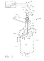
- FIG 3 is a perspective view of an exemplary stator vane 100 that may be utilized with compressor 14 shown in Figures 1 and 2 in either a fixed or variable configuration.
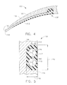
- Figure 4 is a top sectional view of the stator vane shown in Figure 3 taken through section 4-4.
- Figure 5 is a section view of the stator vane shown in Figure 3 taken through section 5-5.
- Stator vane 100 includes an airfoil 102 and an integral vane stem 104 that is used for mounting stator vane 100 within gas turbine engine 10. More specifically, vane stem 104 includes a first or radially outer end 106 that in the exemplary embodiment is coupled to lever arm 80, and a second or radially inner root 108 that is coupled to airfoil 102.
- airfoil 102 is formed unitarily with vane stem 104 to form a unitary stator vane 100.
- Each airfoil 102 includes a first sidewall 110 and a second sidewall 112.
- first and/or second sidewalls 110 and/or 112 may be contoured to improve aerodynamic performance.
- first sidewall 110 is convex and defines a suction side of airfoil 102
- second sidewall 112 is concave and defines a pressure side of airfoil 102.
- Sidewalls 110 and 112 are joined at a leading edge 114 and at an axially-spaced trailing edge 116 of airfoil 102. More specifically, airfoil trailing edge 116 is spaced chordwise and downstream from airfoil leading edge 114.
- First and second sidewalls 110 and 112, respectively, extend longitudinally or radially outward in span from an airfoil root 118 to vane stem 104.
- stator vane 100 may be coupled to inner shroud 82.
- each stator vane 100 is fabricated utilizing a metallic material such as, but not limited to, titanium.
- each stator vane 100 is fabricated utilizing a composite material.
- stator vane 100 includes an opening 130 that extends from vane stem radially outer end 106, substantially concentrically through vane stem 104, to vane stem radially inner root 108.
- opening 130 has a diameter 132 that is sized to receive a light probe that will be discussed later herein.
- airfoil 102 includes a groove or slot 140 that is machined into a surface of airfoil 102.
- groove 140 is machined into second sidewall 112, i.e. the concave side of airfoil 102.
- groove 140 is machined into first sidewall 110, i.e. the convex side or airfoil 102.
- Groove 140 includes a first groove portion 142 having a first end 144 that is substantially concentrically aligned with opening 130 and a second end 146.
- First groove portion 142 extends radially inwardly at least partially towards airfoil root 118.
- Groove 140 also includes a second groove portion 148 that extends axially downstream from first groove portion second end 146 towards airfoil trailing edge 116.
- Second groove portion 148 has a first end 150 that is substantially aligned with first groove portion second end 146 and a second groove portion second end 152 that is positioned proximate to airfoil trailing edge 116.
- groove 140 has a substantially L-shaped profile and extends continuously from vane stem 104 to airfoil trailing edge 116.
- Groove 140 has a width 154 and a depth 156 that are sized to receive the light probe discussed below.
- opening 130 and groove 140 form a continuous probe inspection port 158 that extends from the vane stem radially outer end 106, through vane stem 104, radially inwardly towards airfoil root 118, and axially downstream towards airfoil trailing edge 116.
- Gas turbine engine assembly 10 also includes an instrumentation light probe 160 that includes a first end 164 and a second end 166.
- light probe 160 may be fabricated utilizing a plurality of fibers 172 that are encased within a stainless steel sheath 174, for example.
- the optical fibers are encased within a non-metallic sheath.
- at least a portion of light probe 160 is positioned at least partially within inspection port 158 to facilitate securing light probe 160 to stator vane 100. More specifically, during assembly, light probe first end 164 is inserted into vane stem radially outer end 106, fed through vane stem 104, and positioned within groove 140.
- light probe 160 may be configured, by bending for example, such that light probe 160 has a profile that is substantially similar to the profile of groove 140. The light probe 160 is then positioned within groove 140 such that light probe first end 164 is positioned proximate to airfoil trailing edge 116.
- Light probe 160 is then coupled to stator vane 100 such that the light probe 160 emits light downstream from the airfoil trailing edge 116 toward at least one rotor blade, such as compressor rotor blades 52, for example.
- an epoxy material or other adhesive is utilized to facilitate securing light probe 160 in a substantially fixed position within groove 140.
- groove 140 is selectively sized to receive light probe 160 in a friction fit such that an epoxy is not utilized to secure light probe 160 within groove 140.
- light probe 160 is configured to remain substantially permanently with gas turbine engine assembly, such that light probe 160 may be utilized during engine operation, or utilized during an engine maintenance period.
- a light source 170 and a photodetector 176, camera, or the like are coupled to light probe second end 166.
- the light source 170 supplies light through at least one optical fiber 172 to the probe operating end, i.e. light probe first end 164.
- light source 170 is activated such that light is transmitted through light probe 160 to illuminate at least one rotor blade 52.
- the light reflected from rotor blade 52 is received through at least one optical fiber 172 and transmitted through at least one fiber 178 to light probe second end 166 wherein the light signals are reflected by the rotor blades back to at least one optical fiber 180 which then transmits the light signal back to photodetector 176, for example.
- the received light signals may then be used to measure operating characteristics of the blades 52, such as blade vibration, axial displacement of the blades, changes in the blade contour, and/or untwist of the blade, caused by centrifugal forces.
- FIG 6 is a perspective view of an exemplary stator vane 200 including light probe 160 that may be utilized with the gas turbine engine shown in Figure 1.
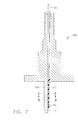
- Figure 7 is a side cutaway view of the stator vane shown in Figure 6.
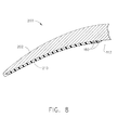
- Figure 8 is a top section view of the stator vane shown in Figure 6 taken through section 8-8.
- Stator vane 200 includes an airfoil 202 and an integral vane stem 104 that is used for mounting stator vane 200 within gas turbine engine 10. More specifically, vane stem 104 includes a first or radially outer end 106 that in the exemplary embodiment is coupled to lever arm 80 shown in Figure 2, and a second or radially inner root 108 that is coupled to airfoil 202.
- airfoil 202 is formed unitarily with vane stem 104 to form a unitary stator vane 100.
- Each airfoil 202 includes first sidewall 110 and second sidewall 112.
- first and/or second sidewalls 110 and/or 112 may be contoured to improve aerodynamic performance.
- first sidewall 110 is convex and defines a suction side of airfoil 202
- second sidewall 112 is concave and defines a pressure side of airfoil 202.
- Sidewalls 110 and 112 are joined at a leading edge 114 and at an axially-spaced trailing edge 116 of airfoil 202. More specifically, airfoil trailing edge 116 is spaced chordwise and downstream from airfoil leading edge 114.
- First and second sidewalls 110 and 112, respectively, extend longitudinally or radially outward in span from an airfoil root 118 to vane stem 104.
- stator vane 200 may be coupled to inner shroud 82.
- each stator vane 200 is fabricated utilizing a metallic material such as, but not limited to, titanium.
- each stator vane 200 is fabricated utilizing a composite material.
- stator vane 200 includes an opening 130 that extends from vane stem radially outer end 106, through vane stem 104, to vane stem radially inner root 108.
- opening 130 has a diameter 132 that is sized to receive light probe 160.
- stator vane 200 does not include a groove or slot 140 that is machined into a surface of airfoil 202. Rather, light probe 160 is coupled to a surface of airfoil 202.
- light probe 160 is coupled to second sidewall 112, i.e. the concave side of airfoil 202.
- light probe 160 may be coupled to first sidewall 110, i.e. the convex side or airfoil 202.
- additional material 210 is bonded to an exterior surface of airfoil 202 to secure light probe 160 to airfoil 202.
- light probe 160 is positioned along the exterior surface of airfoil 202.
- Additional material 210 is then applied to airfoil 202 to facilitate securing light probe 160 to airfoil 202.
- the additional material 210 is then machined or feathered such that an aerodynamic profile of airfoil 202 is optimized.
- airfoil 202 is machined to facilitate forming a relatively smooth airflow path over and/or around light probe 160 and therefore reduce and/or eliminate any airflow disruptions that may occur as a result of mounting light probe 160 to an exterior surface of airfoil 202.
- light probe 160 may be coupled to any known airfoils by simply adhering the light probe 160 to airfoil 202 utilizing additional material 210.
- the additional material 210 may be either a metallic material similar to the metallic material utilized to fabricate airfoil 202, a composite material, and/or a resin product.
- FIG 9 is a perspective view of an exemplary stator vane 300 including light probe 160 that may be utilized with the gas turbine engine shown in Figure 1.
- Stator vane 300 includes an airfoil 302 and an integral vane stem 104 that is used for mounting stator vane 300 within gas turbine engine 10. More specifically, vane stem 104 includes a first or radially outer end 106 that in the exemplary embodiment is coupled to lever arm 80, and a second or radially inner root 108 that is coupled to airfoil 302.
- airfoil 302 is formed unitarily with vane stem 104 to form a unitary stator vane 300.
- stator vane 300 includes an opening 130 that extends from vane stem radially outer end 106, through vane stem 104, to vane stem radially inner root 108.
- opening 130 has a diameter 132 that is sized to receive light probe 160.
- stator vane 300 does not include a groove or slot 140 that is machined into a surface of airfoil 302. Rather stator vane airfoil 302 includes an airfoil opening 310 that extends at least partially through airfoil 302 such that at least a portion of the airfoil opening 310 is substantially concentrically aligned with the vane stem opening 130.
- airfoil opening 310 includes a first airfoil opening portion 312 having a first end 314 that is substantially concentrically aligned with opening 130 and a second end 316.
- First portion 312 extends at least partially radially inwardly toward radially inner root 108 of vane stem 104.
- Airfoil opening 310 also includes a second airfoil opening portion 320 having a first end 322 that is substantially perpendicular to first end 314.
- second airfoil opening portion 320 extends downstream from first airfoil opening portion second end 316 towards airfoil trailing edge 116.
- airfoil opening 310 has a substantially L-shaped profile and extends continuously from vane stem 104 to airfoil trailing edge 116. Airfoil opening 310 has a diameter 330 that is sized to receive light probe 160 therethrough.
- vane stem opening 130 and airfoil opening 310 form a continuous probe inspection port 158 that extends from the vane stem radially outer end 106, through vane stem 104, radially inwardly towards airfoil root 118, and downstream towards airfoil trailing edge 116.
- a method for manufacturing a stator vane includes coupling an airfoil to a vane stem, the airfoil including a first sidewall and a second sidewall, the first and second sidewalls joined at a leading edge and at an axially-spaced trailing edge, forming an opening through the vane stem, inserting a light probe through the vane stem opening, and securing the light probe to the airfoil.
- stator vane that includes an integral light probe.
- the stator vane may be utilized with a wide variety of gas turbine engine applications. Moreover the stator vane may be modified to use with other turbines such as steam turbines for example.
- the exemplary stator vanes described herein are configured to be utilized within a gas turbine engine compressor. The stator vanes may be fixed within the compressor or may be coupled to a variable stator vane assembly such that the stator vanes are movable within the compressor.
- the invention is described with respect to a single stator vane including a light probe, it should be realized that a plurality of stator vanes each including an integral light probe may be installed within a single gas turbine engine.
- a stator vane that includes an integral light probe may be installed in a plurality of compressor stages to facilitate measuring the frequency of the rotor blades in each compressor stage.
- the stator vane is positioned axially forward of a respective row of rotor blades.
- the light probe is then coupled to the stator vane such that the light probe is mounted axially or along the flow stream and turned radially outwardly such that one end of the light probe extends radially outwardly through the stator vane stem such that the light probe extends from the compressor casing to facilitate coupling the light probe to external equipment.
- the light probe faces in an approximately downstream axial direction along the airfoil with the capability of viewing the rotor blade leading edge.
- the light probe is configured to measure differences in blade frequency indicating that the blade has experienced damage and a crack is growing.
- stator vane described herein including the light source is positioned axially forward from the rotor blades and as such any dirt and/or debris that is centrifuged radially outward by the rotor blades with not be deposited on the light probe.
- the dirt or debris does accumulate on the light probe thereby increasing the effectiveness of the light probe to accurately measure the frequency of the rotor blades.
Landscapes
- Engineering & Computer Science (AREA)
- Mechanical Engineering (AREA)
- General Engineering & Computer Science (AREA)
- Turbine Rotor Nozzle Sealing (AREA)
- Structures Of Non-Positive Displacement Pumps (AREA)
- Control Of Turbines (AREA)
Abstract
Description
- This invention relates generally to gas turbine engines, and more particularly, to a gas turbine engine stator vane that includes an integral light probe for measuring operating characteristics of rotor blades.
- Gas turbine engines typically include high and low pressure compressors, a combustor, and at least one turbine. The compressors compress air which is mixed with fuel and channeled to the combustor. The mixture is then ignited for generating hot combustion gases, and the combustion gases are channeled to the turbine which extracts energy from the combustion gases for powering the compressor, as well as producing useful work to propel an aircraft in flight or to power a load, such as an electrical generator.
- When gas turbine engines operate in various conditions, foreign objects may be ingested into the engine. More specifically, various types of foreign objects may be entrained in the inlet of the gas turbine engine, ranging from large birds, such as sea gulls, to hailstones, sand, and rain. The foreign objects may impact a rotor blade resulting in a portion being liberated from the rotor blade. Such a condition, known as foreign object damage, may cause relatively sharp notches to be formed in the leading edges of the rotor blade. These sharp notches in effect are stress concentrations which may reduce the fatigue capability of the rotor blade. If this condition is not resolved, a portion of the airfoil, usually the tip, may be liberated, thus changing the frequency of the airfoil. When this occurs there will be a flow disturbance around the blade with the missing tip or tip corner. This disturbance can cause a driving force which will drive adjacent airfoils to possible failure.
- To measure a frequency change in the rotor blade, a strain gage may be utilized. However, strain gages may not have the desired precision to measure a relatively small change in the rotor blade frequency. Additionally, a light probe may be utilized to measure the change in rotor blade frequency. More specifically, at least one known gas turbine engine includes a threaded opening that is defined through the gas turbine engine casing. The known light probe is inserted through the casing opening to illuminate the rotor blade. However, during operation, the rotor blade tends to centrifuge dirt and/or debris radially outward towards the light probe. As a result, the dirt or debris may accumulate on the light probe thereby lowering the effectiveness of the light probe to accurately measure the frequency of the rotor blades.
- In one aspect according to the present invention, a method for manufacturing a stator vane is provided. The method includes coupling an airfoil to a vane stem, the airfoil including a first sidewall and a second sidewall, the first and second sidewalls joined at a leading edge and at an axially-spaced trailing edge, and forming an opening at least partially through the vane stem, the opening sized to receive a light probe therein.
- In another aspect, a stator vane is provided. The stator vane includes a vane stem, an airfoil coupled to the vane stem, the airfoil including a first sidewall and a second sidewall, the first and second sidewalls joined at a leading edge and at an axially-spaced trailing edge, and a probe inspection port including an opening extending at least partially through the vane stem, the opening sized to receive a light probe therein.
- In a further aspect, a gas turbine engine assembly is provided. The gas turbine engine assembly includes a compressor, a combustor, and a turbine coupled to the compressor. The compressor includes a rotor assembly including a plurality of rotor stages, each rotor stage including a plurality of rotor blades, and a stator vane assembly including a plurality of stator vanes stages, each stator vane stage including a plurality of stator vanes, at least one of the stator vane stages coupled upstream from at least one of the rotor stages, at least one of the stator vanes. At least one of the stator vanes includes a vane stem, an airfoil coupled to the vane stem, the airfoil including a first sidewall and a second sidewall, the first and second sidewalls joined at a leading edge and at an axially-spaced trailing edge, and a probe inspection port including an opening extending at least partially through the vane stem, the opening sized to receive a light probe therein.
- Various aspects and embodiments of the present invention will now be described in connection with the accompanying drawings, in which:
- Figure 1 is a cross-sectional view of an exemplary gas turbine engine;
- Figure 2 is a cross-sectional view of a section of an exemplary high pressure compressor used with the gas turbine engine shown in Figure 1;
- Figure 3 is a perspective view of an exemplary stator vane including a light probe that may be utilized with the gas turbine engine shown in Figure 1;
- Figure 4 is a top sectional view of a portion of the stator vane shown in Figure 3 taken through section 4-4;
- Figure 5 is a section view of the stator vane shown in Figure 3 taken through section 5-5;
- Figure 6 is a perspective view of another exemplary stator vane including a light probe that may be utilized with the gas turbine engine shown in Figure 1;
- Figure 7 is a side cutaway view of the stator vane shown in Figure 6;
- Figure 8 is a top section view of the stator vane shown in Figure 6 taken through section 8-8; and
- Figure 9 is a perspective view of an another exemplary stator vane including a light probe that may be utilized with the gas turbine engine shown in Figure 1.
- Figure 1 is a schematic illustration of an exemplary gas
turbine engine assembly 10 having alongitudinal axis 11. Gasturbine engine assembly 10 includes afan assembly 12, and a coregas turbine engine 13 that includes ahigh pressure compressor 14, acombustor 16, and ahigh pressure turbine 18. In the exemplary embodiment, gasturbine engine assembly 10 also includes alow pressure turbine 20 and amulti-stage booster compressor 22. -
Fan assembly 12 includes an array offan blades 24 extending radially outward from arotor disk 26.Engine 10 has anintake side 28 and anexhaust side 30. In the exemplary embodiment,gas turbine engine 10 is a GE90 gas turbine engine that is available from General Electric Company, Cincinnati, Ohio.Fan assembly 12,booster 22, and low-pressure turbine 20 are coupled together by afirst rotor shaft 31, andcompressor 14 and high-pressure turbine 18 are coupled together by asecond rotor shaft 32. - In operation, air flows through
fan assembly 12 and compressed air is supplied tohigh pressure compressor 14 throughbooster 22. The booster discharge air is channeled tocompressor 14 wherein the airflow is further compressed and delivered tocombustor 16. Hot products of combustion (not shown in Figure 1) fromcombustor 16 are utilized to driveturbines turbine 20 is utilized to drivefan assembly 12 andbooster 22 by way ofshaft 31.Engine 10 is operable at a range of operating conditions between design operating conditions and off-design operating conditions. - Figure 2 is a schematic view of a section of
high pressure compressor 14.Compressor 14 includes a plurality ofstages 50 wherein eachstage 50 includes a row ofrotor blades 52 and a row of variablestator vane assemblies 56.Rotor blades 52 are typically supported byrotor disks 58, and are connected torotor shaft 32.Rotor shaft 32 is a high pressure shaft that is also connected to high pressure turbine 18 (shown in Figure 1).Compressor 14 is surrounded by acasing 62 that supports variablestator vane assemblies 56. - Each variable
stator vane assembly 56 includes avariable vane 74 and avane stem 76. Vane stem 76 protrudes through an opening 78 incasing 62. Eachvariable vane assembly 56 also includes alever arm 80 extending fromvariable vane 74 that is utilized to rotatevariable vanes 74. Vanes 74 are oriented relative to a flow path throughcompressor 14 to control air flow therethrough. In addition, at least somevanes 74 are attached to aninner shroud 82. Although, Figure 2 illustratescompressor 14 including a plurality ofvariable stator vanes 74, it should be realized thatcompressor 14 may include a plurality of fixed stator vanes utilized in lieu ofvariable stator vanes 74. - Figure 3 is a perspective view of an
exemplary stator vane 100 that may be utilized withcompressor 14 shown in Figures 1 and 2 in either a fixed or variable configuration. Figure 4 is a top sectional view of the stator vane shown in Figure 3 taken through section 4-4. Figure 5 is a section view of the stator vane shown in Figure 3 taken through section 5-5.Stator vane 100 includes anairfoil 102 and anintegral vane stem 104 that is used formounting stator vane 100 withingas turbine engine 10. More specifically,vane stem 104 includes a first or radiallyouter end 106 that in the exemplary embodiment is coupled tolever arm 80, and a second or radiallyinner root 108 that is coupled toairfoil 102. In the exemplary embodiment,airfoil 102 is formed unitarily withvane stem 104 to form aunitary stator vane 100. - Each
airfoil 102 includes afirst sidewall 110 and asecond sidewall 112. In one embodiment, either first and/orsecond sidewalls 110 and/or 112 may be contoured to improve aerodynamic performance. In the exemplary embodiment,first sidewall 110 is convex and defines a suction side ofairfoil 102, andsecond sidewall 112 is concave and defines a pressure side ofairfoil 102.Sidewalls leading edge 114 and at an axially-spacedtrailing edge 116 ofairfoil 102. More specifically,airfoil trailing edge 116 is spaced chordwise and downstream fromairfoil leading edge 114. First andsecond sidewalls airfoil root 118 tovane stem 104. As shown in Figure 2, in some embodiments,stator vane 100 may be coupled toinner shroud 82. In the exemplary embodiment, eachstator vane 100 is fabricated utilizing a metallic material such as, but not limited to, titanium. In an alternative embodiment, eachstator vane 100 is fabricated utilizing a composite material. - As shown in Figure 3,
stator vane 100 includes anopening 130 that extends from vane stem radiallyouter end 106, substantially concentrically throughvane stem 104, to vane stem radiallyinner root 108. In the exemplary embodiment, opening 130 has adiameter 132 that is sized to receive a light probe that will be discussed later herein. Additionally,airfoil 102 includes a groove or slot 140 that is machined into a surface ofairfoil 102. In the exemplary embodiment,groove 140 is machined intosecond sidewall 112, i.e. the concave side ofairfoil 102. Optionally,groove 140 is machined intofirst sidewall 110, i.e. the convex side orairfoil 102.Groove 140 includes afirst groove portion 142 having afirst end 144 that is substantially concentrically aligned withopening 130 and asecond end 146.First groove portion 142 extends radially inwardly at least partially towardsairfoil root 118. - Groove 140 also includes a
second groove portion 148 that extends axially downstream from first groove portionsecond end 146 towardsairfoil trailing edge 116.Second groove portion 148 has afirst end 150 that is substantially aligned with first groove portionsecond end 146 and a second groove portion second end 152 that is positioned proximate toairfoil trailing edge 116. As such, and as shown in Figure 3, groove 140 has a substantially L-shaped profile and extends continuously from vane stem 104 toairfoil trailing edge 116.Groove 140 has awidth 154 and adepth 156 that are sized to receive the light probe discussed below. - Accordingly, the combination of
opening 130 and groove 140 form a continuousprobe inspection port 158 that extends from the vane stem radiallyouter end 106, throughvane stem 104, radially inwardly towardsairfoil root 118, and axially downstream towardsairfoil trailing edge 116. - Gas
turbine engine assembly 10 also includes aninstrumentation light probe 160 that includes afirst end 164 and asecond end 166. In the exemplary embodiment,light probe 160 may be fabricated utilizing a plurality offibers 172 that are encased within astainless steel sheath 174, for example. Optionally, the optical fibers are encased within a non-metallic sheath. As shown in Figure 3, at least a portion oflight probe 160 is positioned at least partially withininspection port 158 to facilitate securinglight probe 160 tostator vane 100. More specifically, during assembly, light probefirst end 164 is inserted into vane stem radiallyouter end 106, fed throughvane stem 104, and positioned withingroove 140. For example,light probe 160 may be configured, by bending for example, such thatlight probe 160 has a profile that is substantially similar to the profile ofgroove 140. Thelight probe 160 is then positioned withingroove 140 such that light probefirst end 164 is positioned proximate toairfoil trailing edge 116. -
Light probe 160 is then coupled tostator vane 100 such that thelight probe 160 emits light downstream from theairfoil trailing edge 116 toward at least one rotor blade, such ascompressor rotor blades 52, for example. In the exemplary embodiment, an epoxy material or other adhesive is utilized to facilitate securinglight probe 160 in a substantially fixed position withingroove 140. Optionally,groove 140 is selectively sized to receivelight probe 160 in a friction fit such that an epoxy is not utilized to securelight probe 160 withingroove 140. - As such,
light probe 160 is configured to remain substantially permanently with gas turbine engine assembly, such thatlight probe 160 may be utilized during engine operation, or utilized during an engine maintenance period. For example, to utilizelight probe 160, alight source 170 and a photodetector 176, camera, or the like, are coupled to light probesecond end 166. Thelight source 170 supplies light through at least oneoptical fiber 172 to the probe operating end, i.e. light probefirst end 164. - In use,
light source 170 is activated such that light is transmitted throughlight probe 160 to illuminate at least onerotor blade 52. The light reflected fromrotor blade 52 is received through at least oneoptical fiber 172 and transmitted through at least onefiber 178 to light probesecond end 166 wherein the light signals are reflected by the rotor blades back to at least oneoptical fiber 180 which then transmits the light signal back to photodetector 176, for example. The received light signals may then be used to measure operating characteristics of theblades 52, such as blade vibration, axial displacement of the blades, changes in the blade contour, and/or untwist of the blade, caused by centrifugal forces. - Figure 6 is a perspective view of an
exemplary stator vane 200 includinglight probe 160 that may be utilized with the gas turbine engine shown in Figure 1. Figure 7 is a side cutaway view of the stator vane shown in Figure 6. Figure 8 is a top section view of the stator vane shown in Figure 6 taken through section 8-8.Stator vane 200 includes anairfoil 202 and an integral vane stem 104 that is used for mountingstator vane 200 withingas turbine engine 10. More specifically, vane stem 104 includes a first or radiallyouter end 106 that in the exemplary embodiment is coupled tolever arm 80 shown in Figure 2, and a second or radiallyinner root 108 that is coupled toairfoil 202. As discussed above, in the exemplary embodiment,airfoil 202 is formed unitarily with vane stem 104 to form aunitary stator vane 100. - Each
airfoil 202 includesfirst sidewall 110 andsecond sidewall 112. In one embodiment, either first and/orsecond sidewalls 110 and/or 112 may be contoured to improve aerodynamic performance. In the exemplary embodiment,first sidewall 110 is convex and defines a suction side ofairfoil 202, andsecond sidewall 112 is concave and defines a pressure side ofairfoil 202.Sidewalls leading edge 114 and at an axially-spacedtrailing edge 116 ofairfoil 202. More specifically,airfoil trailing edge 116 is spaced chordwise and downstream fromairfoil leading edge 114. First andsecond sidewalls airfoil root 118 tovane stem 104. As shown in Figure 2, in some embodiments,stator vane 200 may be coupled toinner shroud 82. In the exemplary embodiment, eachstator vane 200 is fabricated utilizing a metallic material such as, but not limited to, titanium. In an alternative embodiment, eachstator vane 200 is fabricated utilizing a composite material. - As shown in Figure 6,
stator vane 200 includes anopening 130 that extends from vane stem radiallyouter end 106, throughvane stem 104, to vane stem radiallyinner root 108. In the exemplary embodiment, opening 130 has adiameter 132 that is sized to receivelight probe 160. - In this exemplary embodiment,
stator vane 200 does not include a groove or slot 140 that is machined into a surface ofairfoil 202. Rather,light probe 160 is coupled to a surface ofairfoil 202. For example, in one embodiment,light probe 160 is coupled tosecond sidewall 112, i.e. the concave side ofairfoil 202. Optionally,light probe 160 may be coupled tofirst sidewall 110, i.e. the convex side orairfoil 202. - More specifically, and as shown in Figures 6 and 7, to fabricate
stator vane 200,additional material 210 is bonded to an exterior surface ofairfoil 202 to securelight probe 160 toairfoil 202. Specifically,light probe 160 is positioned along the exterior surface ofairfoil 202.Additional material 210 is then applied toairfoil 202 to facilitate securinglight probe 160 toairfoil 202. Theadditional material 210 is then machined or feathered such that an aerodynamic profile ofairfoil 202 is optimized. Specifically,airfoil 202 is machined to facilitate forming a relatively smooth airflow path over and/or aroundlight probe 160 and therefore reduce and/or eliminate any airflow disruptions that may occur as a result of mountinglight probe 160 to an exterior surface ofairfoil 202. As such,light probe 160 may be coupled to any known airfoils by simply adhering thelight probe 160 toairfoil 202 utilizingadditional material 210. In the exemplary embodiment, theadditional material 210 may be either a metallic material similar to the metallic material utilized to fabricateairfoil 202, a composite material, and/or a resin product. - Figure 9 is a perspective view of an
exemplary stator vane 300 includinglight probe 160 that may be utilized with the gas turbine engine shown in Figure 1.Stator vane 300 includes anairfoil 302 and an integral vane stem 104 that is used for mountingstator vane 300 withingas turbine engine 10. More specifically, vane stem 104 includes a first or radiallyouter end 106 that in the exemplary embodiment is coupled tolever arm 80, and a second or radiallyinner root 108 that is coupled toairfoil 302. As discussed above, in the exemplary embodiment,airfoil 302 is formed unitarily with vane stem 104 to form aunitary stator vane 300. - As shown in Figure 9,
stator vane 300 includes anopening 130 that extends from vane stem radiallyouter end 106, throughvane stem 104, to vane stem radiallyinner root 108. In the exemplary embodiment, opening 130 has adiameter 132 that is sized to receivelight probe 160. In this exemplary embodiment,stator vane 300 does not include a groove or slot 140 that is machined into a surface ofairfoil 302. Ratherstator vane airfoil 302 includes anairfoil opening 310 that extends at least partially throughairfoil 302 such that at least a portion of theairfoil opening 310 is substantially concentrically aligned with thevane stem opening 130. - More specifically, and as shown in Figure 9,
airfoil opening 310 includes a firstairfoil opening portion 312 having a first end 314 that is substantially concentrically aligned withopening 130 and asecond end 316.First portion 312 extends at least partially radially inwardly toward radiallyinner root 108 ofvane stem 104. Airfoil opening 310 also includes a secondairfoil opening portion 320 having afirst end 322 that is substantially perpendicular to first end 314. In the exemplary embodiment, secondairfoil opening portion 320 extends downstream from first airfoil opening portionsecond end 316 towardsairfoil trailing edge 116. As such, and as shown in Figure 9,airfoil opening 310 has a substantially L-shaped profile and extends continuously from vane stem 104 toairfoil trailing edge 116. Airfoil opening 310 has adiameter 330 that is sized to receivelight probe 160 therethrough. - Accordingly, the combination of vane stem opening 130 and
airfoil opening 310 form a continuousprobe inspection port 158 that extends from the vane stem radiallyouter end 106, throughvane stem 104, radially inwardly towardsairfoil root 118, and downstream towardsairfoil trailing edge 116. - A method for manufacturing a stator vane includes coupling an airfoil to a vane stem, the airfoil including a first sidewall and a second sidewall, the first and second sidewalls joined at a leading edge and at an axially-spaced trailing edge, forming an opening through the vane stem, inserting a light probe through the vane stem opening, and securing the light probe to the airfoil.
- Described herein is a stator vane that includes an integral light probe. The stator vane may be utilized with a wide variety of gas turbine engine applications. Moreover the stator vane may be modified to use with other turbines such as steam turbines for example. The exemplary stator vanes described herein are configured to be utilized within a gas turbine engine compressor. The stator vanes may be fixed within the compressor or may be coupled to a variable stator vane assembly such that the stator vanes are movable within the compressor. Moreover, although the invention is described with respect to a single stator vane including a light probe, it should be realized that a plurality of stator vanes each including an integral light probe may be installed within a single gas turbine engine. For example, a stator vane that includes an integral light probe may be installed in a plurality of compressor stages to facilitate measuring the frequency of the rotor blades in each compressor stage.
- More specifically, the stator vane is positioned axially forward of a respective row of rotor blades. The light probe is then coupled to the stator vane such that the light probe is mounted axially or along the flow stream and turned radially outwardly such that one end of the light probe extends radially outwardly through the stator vane stem such that the light probe extends from the compressor casing to facilitate coupling the light probe to external equipment. Moreover, the light probe faces in an approximately downstream axial direction along the airfoil with the capability of viewing the rotor blade leading edge. During operation, the light probe is configured to measure differences in blade frequency indicating that the blade has experienced damage and a crack is growing.
- As such, the stator vane described herein including the light source is positioned axially forward from the rotor blades and as such any dirt and/or debris that is centrifuged radially outward by the rotor blades with not be deposited on the light probe. As a result, the dirt or debris does accumulate on the light probe thereby increasing the effectiveness of the light probe to accurately measure the frequency of the rotor blades.
- While the invention has been described in terms of various specific embodiments, those skilled in the art will recognize that the invention can be practiced with modification within the spirit and scope of the claims.
Claims (10)
- A stator vane (100), comprising:a vane stem (104);an airfoil (102) coupled to said vane stem, said airfoil comprising a first sidewall (110) and a second sidewall (112), said first and second sidewalls joined at a leading edge (114) and at an axially-spaced trailing edge (116); anda probe inspection port (158) comprising an opening (78) extending through said vane stem, said opening sized to receive a light probe (160) therein.
- The stator vane (100) in accordance with Claim 1, wherein said probe inspection port (158) is formed substantially concentrically within said vane stem (76) and extends radially inwardly towards a radially inner end of said airfoil (102) and axially downstream towards said airfoil trailing edge (116).
- The stator vane (100) in accordance with Claim 1 or Claim 2, wherein said probe inspection port (158) further comprises a groove (140) formed in at least one of said first and second sidewalls (110,112), at least a portion of said groove is substantially concentrically aligned with said vane stem opening (78).
- The stator vane (100) in accordance with Claim 3, wherein said groove (140) has a width (154) and a depth (156) that are each greater than a diameter (330) of the light probe (160).
- The stator vane (100) in accordance with any preceding Claim, wherein said probe inspection port (158) further comprises an opening (310) extending through said airfoil (102), at least a portion of said airfoil substantially concentrically aligned with said vane stem opening (130).
- The stator vane in accordance with any preceding Claim, wherein said probe inspection port (158) further comprises a groove (140) formed on an exterior surface of at least one of said first and second sidewalls (110,112), at least a portion of said groove is substantially concentrically aligned with said vane stem opening (78).
- A gas turbine engine assembly, comprising:a compressor (14);a combustor (16); anda turbine coupled to said compressor, at least one of said compressor and said turbine comprisinga rotor assembly including a plurality of rotor blades (52); anda stator vane assembly (56) including a plurality of stator vanes (74), at least one of said stator vanes comprisinga vane stem (104);an airfoil (102) coupled to said vane stem, said airfoil comprising a first sidewall (110) and a second sidewall (112), said first and second sidewalls joined at a leading edge (114) and at an axially-spaced trailing edge (116); anda probe inspection port (158) comprising an opening (130) extending through said vane stem (164), said opening sized to receive a light probe (160) therein.
- The gas turbine engine assembly in accordance with Claim 7, wherein said probe inspection port (158) is formed substantially concentrically within said vane stem (104) and extends radially inwardly towards a radially inner end of said airfoil (102) and axially downstream towards said airfoil trailing edge (116).
- The gas turbine engine assembly in accordance with Claim 7 or Claim 8, further comprising a light probe (160) having a first end (144) and a second end (146), said light probe positioned within said probe inspection port (158) such that said light probe first end (164) extends radially outwardly from said gas turbine vane stem (104) and such that said light probe second end (166) is positioned proximate to said airfoil trailing edge (116).
- The gas turbine engine assembly in accordance with any one of Claims 7 to 9, further comprising a bonding material (210) that is utilized to maintain said light probe (160) within said probe inspection port (158).
Applications Claiming Priority (1)
| Application Number | Priority Date | Filing Date | Title |
|---|---|---|---|
| US11/461,023 US7527471B2 (en) | 2006-07-31 | 2006-07-31 | Stator vane and gas turbine engine assembly including same |
Publications (3)
| Publication Number | Publication Date |
|---|---|
| EP1884626A2 true EP1884626A2 (en) | 2008-02-06 |
| EP1884626A3 EP1884626A3 (en) | 2012-11-21 |
| EP1884626B1 EP1884626B1 (en) | 2014-05-21 |
Family
ID=38370723
Family Applications (1)
| Application Number | Title | Priority Date | Filing Date |
|---|---|---|---|
| EP07112080.2A Ceased EP1884626B1 (en) | 2006-07-31 | 2007-07-09 | Gas turbine stator vane assembly comprising a probe inspection port |
Country Status (3)
| Country | Link |
|---|---|
| US (1) | US7527471B2 (en) |
| EP (1) | EP1884626B1 (en) |
| JP (1) | JP5038802B2 (en) |
Cited By (2)
| Publication number | Priority date | Publication date | Assignee | Title |
|---|---|---|---|---|
| WO2012156110A3 (en) * | 2011-05-13 | 2013-01-31 | Bosch Mahle Turbo Systems Gmbh & Co. Kg | Variable turbine/compressor geometry |
| CN109372788A (en) * | 2018-12-10 | 2019-02-22 | 中国航发四川燃气涡轮研究院 | A kind of combined type blade profile probe measurement method of variable stator vane angle inlet air flow parameter |
Families Citing this family (19)
| Publication number | Priority date | Publication date | Assignee | Title |
|---|---|---|---|---|
| US7632064B2 (en) * | 2006-09-01 | 2009-12-15 | United Technologies Corporation | Variable geometry guide vane for a gas turbine engine |
| US8251579B2 (en) * | 2007-07-16 | 2012-08-28 | Rtd Company | Robust stator winding temperature sensor |
| DE102011077908A1 (en) * | 2011-06-21 | 2012-12-27 | Siemens Aktiengesellschaft | Gas turbine with pyrometer |
| US9103228B2 (en) | 2011-08-08 | 2015-08-11 | General Electric Company | Variable stator vane control system |
| JP5916510B2 (en) * | 2012-05-16 | 2016-05-11 | 三菱重工業株式会社 | Manufacturing method of blade for rotary machine and balance weight casting jig used therefor |
| US9297720B2 (en) * | 2012-12-21 | 2016-03-29 | United Technologies Corporation | Gas turbine engine vane embedded beam interrupt optical tip-timing probe system |
| CA2903738A1 (en) | 2013-03-07 | 2014-09-12 | Rolls-Royce Canada, Ltd. | Gas turbine engine comprising an outboard insertion system of vanes and corresponding assembling method |
| FR3066779B1 (en) * | 2017-05-26 | 2020-04-03 | Safran Aircraft Engines | DEVICE FOR MEASURING PARAMETERS OF AN AERODYNAMIC FLOW FOR A TURBOMACHINE BLADE, BLADE AND A TURBOMACHINE BLADE EQUIPPED WITH SAID MEASUREMENT DEVICE |
| CN107701514A (en) * | 2017-09-30 | 2018-02-16 | 中国航发沈阳发动机研究所 | Stator blade structure is measured between compressor stage |
| FR3072169B1 (en) * | 2017-10-09 | 2019-10-11 | Safran Aircraft Engines | DEVICE FOR MEASURING AT LEAST ONE PARAMETER OF AERODYNAMIC FLOW OF A TURBOMACHINE EQUIPPED WITH A VIBRATION DAMPING MEANS AND TURBOMACHINE VEIN EQUIPPED WITH SUCH A DEVICE |
| CN109098997A (en) * | 2018-07-19 | 2018-12-28 | 中国航发沈阳发动机研究所 | A kind of compressor passage aerodynamic parameter measurement method |
| US10704413B2 (en) * | 2018-09-06 | 2020-07-07 | Raytheon Technologies Corporation | Systems and methods for variable alignment aerodynamic probes |
| US11230927B2 (en) * | 2019-06-03 | 2022-01-25 | Raytheon Technologies Corporation | Vane airfoil shapes for embedded members |
| KR102295046B1 (en) * | 2020-02-24 | 2021-08-30 | 두산중공업 주식회사 | Stator structure and gas turbine having the same |
| CN111561478A (en) * | 2020-05-22 | 2020-08-21 | 中国航发沈阳发动机研究所 | Stator blade measurement integrated structure |
| US11719165B2 (en) * | 2021-11-03 | 2023-08-08 | Pratt & Whitney Canada Corp. | Air inlet strut for aircraft engine |
| US11840346B2 (en) | 2022-03-28 | 2023-12-12 | Pratt & Whitney Canada Corp. | Strut for aircraft engine |
| US12359672B2 (en) * | 2023-04-18 | 2025-07-15 | Rtx Corporation | Rotor blade inspection system |
| CN116858543A (en) * | 2023-05-29 | 2023-10-10 | 中国航发沈阳发动机研究所 | Rear flow field measuring structure of aero-engine compressor rotor blade |
Family Cites Families (17)
| Publication number | Priority date | Publication date | Assignee | Title |
|---|---|---|---|---|
| US3348414A (en) * | 1964-10-09 | 1967-10-24 | Gen Electric | Gas turbine temperature measuring apparatus |
| US4037473A (en) * | 1971-09-16 | 1977-07-26 | International Harvester Company | Radiation pyrometers with purging fluid |
| US4333239A (en) * | 1980-06-02 | 1982-06-08 | United Technologies Corporation | Method and apparatus for inspecting shrouds of rotor blades |
| US5363463A (en) * | 1982-08-06 | 1994-11-08 | Kleinerman Marcos Y | Remote sensing of physical variables with fiber optic systems |
| US4605315A (en) * | 1984-12-13 | 1986-08-12 | United Technologies Corporation | Temperature probe for rotating machinery |
| US4948264A (en) * | 1986-07-07 | 1990-08-14 | Hook Jr Richard B | Apparatus for indirectly determining the temperature of a fluid |
| US4741203A (en) * | 1986-11-21 | 1988-05-03 | Westinghouse Electric Corp. | Turbine inspection device and associated coil assembly and associated method |
| US4765751A (en) * | 1987-06-29 | 1988-08-23 | United Technologies Corporation | Temperature and pressure probe |
| US5345514A (en) * | 1991-09-16 | 1994-09-06 | General Electric Company | Method for inspecting components having complex geometric shapes |
| US5644394A (en) * | 1994-10-19 | 1997-07-01 | United Technologies Corporation | System for repairing damaged gas turbine engine airfoils |
| US6792809B1 (en) * | 2003-05-02 | 2004-09-21 | Siemens Westinghouse Power Corporation | Self-aligning turbine disc inspection apparatus |
| FR2858371B1 (en) * | 2003-07-31 | 2005-09-30 | Snecma Moteurs | IMPROVED DEVICE FOR SETTING RECTIFIERS OF A TURBOJET COMPRESSOR |
| US6943570B2 (en) * | 2003-09-26 | 2005-09-13 | Honeywell International, Inc. | Device for detecting a crack on a turbine blade of an aircraft engine |
| JP2005214661A (en) * | 2004-01-27 | 2005-08-11 | Toshiba Corp | Power generation equipment monitoring system |
| US6992315B2 (en) * | 2004-03-10 | 2006-01-31 | Siemens Westinghouse Power Corporation | In situ combustion turbine engine airfoil inspection |
| US7190162B2 (en) * | 2004-07-23 | 2007-03-13 | General Electric Company | Methods and apparatus for inspecting a component |
| US7075296B2 (en) * | 2004-11-09 | 2006-07-11 | Siemens Power Generation, Inc. | Inspection carriage for turbine blades |
-
2006
- 2006-07-31 US US11/461,023 patent/US7527471B2/en active Active
-
2007
- 2007-07-09 EP EP07112080.2A patent/EP1884626B1/en not_active Ceased
- 2007-07-27 JP JP2007195872A patent/JP5038802B2/en not_active Expired - Fee Related
Cited By (2)
| Publication number | Priority date | Publication date | Assignee | Title |
|---|---|---|---|---|
| WO2012156110A3 (en) * | 2011-05-13 | 2013-01-31 | Bosch Mahle Turbo Systems Gmbh & Co. Kg | Variable turbine/compressor geometry |
| CN109372788A (en) * | 2018-12-10 | 2019-02-22 | 中国航发四川燃气涡轮研究院 | A kind of combined type blade profile probe measurement method of variable stator vane angle inlet air flow parameter |
Also Published As
| Publication number | Publication date |
|---|---|
| US20080025839A1 (en) | 2008-01-31 |
| EP1884626B1 (en) | 2014-05-21 |
| US7527471B2 (en) | 2009-05-05 |
| JP5038802B2 (en) | 2012-10-03 |
| JP2008032015A (en) | 2008-02-14 |
| EP1884626A3 (en) | 2012-11-21 |
Similar Documents
| Publication | Publication Date | Title |
|---|---|---|
| EP1884626B1 (en) | Gas turbine stator vane assembly comprising a probe inspection port | |
| US8573947B2 (en) | Composite fan blade dovetail root | |
| US7645121B2 (en) | Blade and rotor arrangement | |
| CN102312682B (en) | Composite turbomachine blade and the turbomachine rotor assembly comprising this blade | |
| US7374404B2 (en) | Methods and apparatus for gas turbine engines | |
| US8061997B2 (en) | Damping device for composite blade | |
| US8794925B2 (en) | Root region of a blade for a gas turbine engine | |
| US10018050B2 (en) | Turbomachine rotor blade | |
| EP1887187B1 (en) | Rotor blade | |
| CA2849651C (en) | Axial turbomachine stator with ailerons at the blade roots | |
| US10087764B2 (en) | Airfoil for gas turbine engine | |
| US8834098B2 (en) | Detuned vane airfoil assembly | |
| CN115711177A (en) | Ice reducing mechanism of turbofan engine | |
| US20110116917A1 (en) | Compressor Stator Vane | |
| EP3249232B1 (en) | Compression system for a turbine engine | |
| CN101307776B (en) | Fan vane | |
| GB2427659A (en) | Aerofoil blade and rotor arrangement | |
| US20070098562A1 (en) | Blade | |
| US20110027091A1 (en) | Axial-flow compressor, more particularly one for an aircraft gas-turbine engine | |
| CN120100535A (en) | Guide vane assembly with fixed and variable pitch inlet guide vanes | |
| US12044147B1 (en) | Segmented leading edge guards | |
| CN112554959A (en) | Detuned turbine blade tip shroud | |
| US20200049022A1 (en) | Gas turbine engine mounting arrangement | |
| US20250033760A1 (en) | Blade for an unducted fan of a turbomachine | |
| CA2827566C (en) | Airfoil with tip extension for gas turbine engine |
Legal Events
| Date | Code | Title | Description |
|---|---|---|---|
| PUAI | Public reference made under article 153(3) epc to a published international application that has entered the european phase |
Free format text: ORIGINAL CODE: 0009012 |
|
| AK | Designated contracting states |
Kind code of ref document: A2 Designated state(s): AT BE BG CH CY CZ DE DK EE ES FI FR GB GR HU IE IS IT LI LT LU LV MC MT NL PL PT RO SE SI SK TR |
|
| AX | Request for extension of the european patent |
Extension state: AL BA HR MK YU |
|
| PUAL | Search report despatched |
Free format text: ORIGINAL CODE: 0009013 |
|
| AK | Designated contracting states |
Kind code of ref document: A3 Designated state(s): AT BE BG CH CY CZ DE DK EE ES FI FR GB GR HU IE IS IT LI LT LU LV MC MT NL PL PT RO SE SI SK TR |
|
| AX | Request for extension of the european patent |
Extension state: AL BA HR MK RS |
|
| RIC1 | Information provided on ipc code assigned before grant |
Ipc: G02B 23/24 20060101ALI20121017BHEP Ipc: G01J 5/00 20060101ALI20121017BHEP Ipc: F01D 17/16 20060101AFI20121017BHEP Ipc: F01D 21/00 20060101ALI20121017BHEP |
|
| 17P | Request for examination filed |
Effective date: 20130521 |
|
| AKX | Designation fees paid |
Designated state(s): DE FR GB |
|
| GRAP | Despatch of communication of intention to grant a patent |
Free format text: ORIGINAL CODE: EPIDOSNIGR1 |
|
| RIC1 | Information provided on ipc code assigned before grant |
Ipc: G02B 23/24 20060101ALI20131216BHEP Ipc: F01D 21/00 20060101ALI20131216BHEP Ipc: F01D 17/16 20060101AFI20131216BHEP Ipc: G01J 5/00 20060101ALI20131216BHEP |
|
| INTG | Intention to grant announced |
Effective date: 20140110 |
|
| GRAS | Grant fee paid |
Free format text: ORIGINAL CODE: EPIDOSNIGR3 |
|
| GRAA | (expected) grant |
Free format text: ORIGINAL CODE: 0009210 |
|
| AK | Designated contracting states |
Kind code of ref document: B1 Designated state(s): DE FR GB |
|
| REG | Reference to a national code |
Ref country code: GB Ref legal event code: FG4D |
|
| REG | Reference to a national code |
Ref country code: DE Ref legal event code: R096 Ref document number: 602007036817 Country of ref document: DE Effective date: 20140703 |
|
| REG | Reference to a national code |
Ref country code: DE Ref legal event code: R097 Ref document number: 602007036817 Country of ref document: DE |
|
| PLBE | No opposition filed within time limit |
Free format text: ORIGINAL CODE: 0009261 |
|
| STAA | Information on the status of an ep patent application or granted ep patent |
Free format text: STATUS: NO OPPOSITION FILED WITHIN TIME LIMIT |
|
| 26N | No opposition filed |
Effective date: 20150224 |
|
| REG | Reference to a national code |
Ref country code: DE Ref legal event code: R097 Ref document number: 602007036817 Country of ref document: DE Effective date: 20150224 |
|
| REG | Reference to a national code |
Ref country code: FR Ref legal event code: PLFP Year of fee payment: 10 |
|
| REG | Reference to a national code |
Ref country code: FR Ref legal event code: PLFP Year of fee payment: 11 |
|
| PGFP | Annual fee paid to national office [announced via postgrant information from national office to epo] |
Ref country code: DE Payment date: 20170727 Year of fee payment: 11 Ref country code: GB Payment date: 20170727 Year of fee payment: 11 Ref country code: FR Payment date: 20170726 Year of fee payment: 11 |
|
| REG | Reference to a national code |
Ref country code: DE Ref legal event code: R119 Ref document number: 602007036817 Country of ref document: DE |
|
| GBPC | Gb: european patent ceased through non-payment of renewal fee |
Effective date: 20180709 |
|
| PG25 | Lapsed in a contracting state [announced via postgrant information from national office to epo] |
Ref country code: GB Free format text: LAPSE BECAUSE OF NON-PAYMENT OF DUE FEES Effective date: 20180709 Ref country code: DE Free format text: LAPSE BECAUSE OF NON-PAYMENT OF DUE FEES Effective date: 20190201 Ref country code: FR Free format text: LAPSE BECAUSE OF NON-PAYMENT OF DUE FEES Effective date: 20180731 |