EP1884624A2 - Rotor assembly of a gas turbine and method of assembling a rotor - Google Patents
Rotor assembly of a gas turbine and method of assembling a rotor Download PDFInfo
- Publication number
- EP1884624A2 EP1884624A2 EP07112070A EP07112070A EP1884624A2 EP 1884624 A2 EP1884624 A2 EP 1884624A2 EP 07112070 A EP07112070 A EP 07112070A EP 07112070 A EP07112070 A EP 07112070A EP 1884624 A2 EP1884624 A2 EP 1884624A2
- Authority
- EP
- European Patent Office
- Prior art keywords
- blade
- blades
- geometric parameter
- row
- parameter measurement
- Prior art date
- Legal status (The legal status is an assumption and is not a legal conclusion. Google has not performed a legal analysis and makes no representation as to the accuracy of the status listed.)
- Granted
Links
- 238000000034 method Methods 0.000 title description 15
- 238000005259 measurement Methods 0.000 claims abstract description 49
- 239000002131 composite material Substances 0.000 claims description 3
- 239000007789 gas Substances 0.000 description 14
- 238000013507 mapping Methods 0.000 description 11
- 238000010586 diagram Methods 0.000 description 4
- 238000004519 manufacturing process Methods 0.000 description 4
- 230000035939 shock Effects 0.000 description 4
- 238000013461 design Methods 0.000 description 2
- 238000009826 distribution Methods 0.000 description 2
- 230000002411 adverse Effects 0.000 description 1
- 238000005452 bending Methods 0.000 description 1
- 239000000567 combustion gas Substances 0.000 description 1
- 238000005094 computer simulation Methods 0.000 description 1
- 238000013500 data storage Methods 0.000 description 1
- 230000001419 dependent effect Effects 0.000 description 1
- 238000006073 displacement reaction Methods 0.000 description 1
- 230000000694 effects Effects 0.000 description 1
- 238000009434 installation Methods 0.000 description 1
- 238000012423 maintenance Methods 0.000 description 1
- 239000000203 mixture Substances 0.000 description 1
- 238000012986 modification Methods 0.000 description 1
- 230000004048 modification Effects 0.000 description 1
- 230000010355 oscillation Effects 0.000 description 1
- 238000003860 storage Methods 0.000 description 1
- 238000011144 upstream manufacturing Methods 0.000 description 1
Images


Classifications
-
- F—MECHANICAL ENGINEERING; LIGHTING; HEATING; WEAPONS; BLASTING
- F01—MACHINES OR ENGINES IN GENERAL; ENGINE PLANTS IN GENERAL; STEAM ENGINES
- F01D—NON-POSITIVE DISPLACEMENT MACHINES OR ENGINES, e.g. STEAM TURBINES
- F01D5/00—Blades; Blade-carrying members; Heating, heat-insulating, cooling or antivibration means on the blades or the members
- F01D5/02—Blade-carrying members, e.g. rotors
- F01D5/027—Arrangements for balancing
-
- F—MECHANICAL ENGINEERING; LIGHTING; HEATING; WEAPONS; BLASTING
- F01—MACHINES OR ENGINES IN GENERAL; ENGINE PLANTS IN GENERAL; STEAM ENGINES
- F01D—NON-POSITIVE DISPLACEMENT MACHINES OR ENGINES, e.g. STEAM TURBINES
- F01D5/00—Blades; Blade-carrying members; Heating, heat-insulating, cooling or antivibration means on the blades or the members
- F01D5/12—Blades
- F01D5/26—Antivibration means not restricted to blade form or construction or to blade-to-blade connections or to the use of particular materials
-
- F—MECHANICAL ENGINEERING; LIGHTING; HEATING; WEAPONS; BLASTING
- F01—MACHINES OR ENGINES IN GENERAL; ENGINE PLANTS IN GENERAL; STEAM ENGINES
- F01D—NON-POSITIVE DISPLACEMENT MACHINES OR ENGINES, e.g. STEAM TURBINES
- F01D5/00—Blades; Blade-carrying members; Heating, heat-insulating, cooling or antivibration means on the blades or the members
- F01D5/30—Fixing blades to rotors; Blade roots ; Blade spacers
- F01D5/3007—Fixing blades to rotors; Blade roots ; Blade spacers of axial insertion type
-
- F—MECHANICAL ENGINEERING; LIGHTING; HEATING; WEAPONS; BLASTING
- F04—POSITIVE - DISPLACEMENT MACHINES FOR LIQUIDS; PUMPS FOR LIQUIDS OR ELASTIC FLUIDS
- F04D—NON-POSITIVE-DISPLACEMENT PUMPS
- F04D29/00—Details, component parts, or accessories
- F04D29/26—Rotors specially for elastic fluids
- F04D29/32—Rotors specially for elastic fluids for axial flow pumps
- F04D29/321—Rotors specially for elastic fluids for axial flow pumps for axial flow compressors
- F04D29/322—Blade mountings
-
- F—MECHANICAL ENGINEERING; LIGHTING; HEATING; WEAPONS; BLASTING
- F05—INDEXING SCHEMES RELATING TO ENGINES OR PUMPS IN VARIOUS SUBCLASSES OF CLASSES F01-F04
- F05D—INDEXING SCHEME FOR ASPECTS RELATING TO NON-POSITIVE-DISPLACEMENT MACHINES OR ENGINES, GAS-TURBINES OR JET-PROPULSION PLANTS
- F05D2230/00—Manufacture
- F05D2230/60—Assembly methods
-
- F—MECHANICAL ENGINEERING; LIGHTING; HEATING; WEAPONS; BLASTING
- F05—INDEXING SCHEMES RELATING TO ENGINES OR PUMPS IN VARIOUS SUBCLASSES OF CLASSES F01-F04
- F05D—INDEXING SCHEME FOR ASPECTS RELATING TO NON-POSITIVE-DISPLACEMENT MACHINES OR ENGINES, GAS-TURBINES OR JET-PROPULSION PLANTS
- F05D2260/00—Function
- F05D2260/96—Preventing, counteracting or reducing vibration or noise
-
- Y—GENERAL TAGGING OF NEW TECHNOLOGICAL DEVELOPMENTS; GENERAL TAGGING OF CROSS-SECTIONAL TECHNOLOGIES SPANNING OVER SEVERAL SECTIONS OF THE IPC; TECHNICAL SUBJECTS COVERED BY FORMER USPC CROSS-REFERENCE ART COLLECTIONS [XRACs] AND DIGESTS
- Y02—TECHNOLOGIES OR APPLICATIONS FOR MITIGATION OR ADAPTATION AGAINST CLIMATE CHANGE
- Y02T—CLIMATE CHANGE MITIGATION TECHNOLOGIES RELATED TO TRANSPORTATION
- Y02T50/00—Aeronautics or air transport
- Y02T50/60—Efficient propulsion technologies, e.g. for aircraft
-
- Y—GENERAL TAGGING OF NEW TECHNOLOGICAL DEVELOPMENTS; GENERAL TAGGING OF CROSS-SECTIONAL TECHNOLOGIES SPANNING OVER SEVERAL SECTIONS OF THE IPC; TECHNICAL SUBJECTS COVERED BY FORMER USPC CROSS-REFERENCE ART COLLECTIONS [XRACs] AND DIGESTS
- Y10—TECHNICAL SUBJECTS COVERED BY FORMER USPC
- Y10S—TECHNICAL SUBJECTS COVERED BY FORMER USPC CROSS-REFERENCE ART COLLECTIONS [XRACs] AND DIGESTS
- Y10S416/00—Fluid reaction surfaces, i.e. impellers
- Y10S416/50—Vibration damping features
Definitions
- This invention relates generally to gas turbine engines, and more specifically to methods and systems for ordering blades on a rotor of a rotatable machines.
- Gas turbines are used in different operating environments, such as, to provide propulsion for aircraft and/or to produce power in both land-based and sea-borne power systems.
- At least some known gas turbine engines include a core engine having, in serial flow arrangement, a fan assembly and a high pressure compressor that compress airflow entering the engine.
- a combustor ignites a fuel-air mixture that is then channeled through a turbine nozzle assembly towards high and low pressure turbines.
- the turbines each include a plurality of rotor blades that extract rotational energy from airflow exiting the combustor.
- At least some known turbofan gas turbine engines include a fan assembly that includes a plurality of fan blades extending radially outwardly therefrom. These blades may operate with a relative blade tip Mach number in the transonic regime and may be subject to an operating characteristic called multiple-pure-tone (MPT) noise, sometimes referred to as buzzsaw noise. Buzzsaw noise may occur if at least some blades are oriented differently relative to other blades extending around the circumference of the fan case. Moreover, such noise may occur if blade-to-blade geometry variations exist within the fan and/or if flowfield disturbances are present forward of the fan inlet.
- MPT multiple-pure-tone
- Such flowfield disturbances may be caused by any number of factors including, but not limited to drain leakage, panel splice leakage, or other geometric nonuniformities.
- variations may exist within the fan assembly in the amplitude (strength) and/or spacing of the shockwaves originating from those portions of the blades that have sonic or supersonic velocities.
- the noise due to the shock waves is generally at multiples of the fan shaft per revolution frequency, which is the frequency with which one point on the shaft passes any particular fixed point as it rotates.
- Shock waves of different strengths based on the flowfield disturbances may propagate at different speeds. Accordingly, as the shock waves travel away from the blades, the noise at a blade passing frequency degenerates into a broad spectrum of lower frequency tones as the shock waves merge with each other. Such tones or buzzsaw noise tend to increase passenger annoyance and reduce passenger comfort, and may also adversely affect community noise levels. However, maintaining close manufacturing tolerances to minimize blade to blade orientation and/or geometry variations may be insufficiently capable of minimizing buzzsaw noise.
- a method of ordering blades in a set of blades to be mounted in a rotor of a rotatable machine includes receiving at least one geometric parameter measurement of each blade in a row of blades, determining a maximum difference of the at least one received geometric parameter measurement between adjacent blades in the row of blades, determining a vector sum of at least one of the received geometric parameter measurements, determining a plurality of moment weight vector sums of the rotor, and determining, using a computer, a sequence map of the plurality of blades using the maximum difference of the at least one geometric parameter measurement between adjacent blades in the row of blades, the vector sum of the at least one received geometric parameter measurement, and the plurality of moment weight vector sums.
- a rotor assembly in another aspect, includes a disk including a plurality of circumferentially-spaced blade root slots defined therein, and a plurality of blades, each blade including a root, a tip, and an airfoil therebetween.
- Each blade is positioned within a pre-determined slot based on a blade map wherein the blade map is generated by a computer system configured to receive at least one geometric parameter measurement of a plurality of blades in a row of blades, determine a maximum difference of the at least one received geometric parameter measurement between adjacent blades in the row of blades, determine a vector sum of at least one of the received geometric parameter measurements, determine a plurality of moment weight vector sums of the rotor, and determine a sequence map of each blade using the maximum difference of the at least one geometric parameter measurement between adjacent blades in the row of blades, the vector sum of the at least one received geometric parameter measurement, and the plurality of moment weight vector sum.
- a computer system in another aspect, includes a software code segment programmed to minimize imbalance in a bladed rotor wherein the code segment is configured to receive at least one geometric parameter measurement of a plurality of blades in a row of blades, determine a maximum difference of the at least one received geometric parameter measurements between adjacent blades in the row of blades, determine a vector sum of at least one of the received geometric parameter measurements, determine a plurality of moment weight vector sums of the rotor, and determine a sequence map of each blade using the maximum difference of the at least one geometric parameter measurement between adjacent blades in the row of blades, the vector sum of the at least one received geometric parameter measurement, and the plurality of moment weight vector sums.
- FIG. 1 is a schematic illustration of an exemplary gas turbine engine 10 including a rotor 11 that includes a low-pressure compressor 12, a high-pressure compressor 14, and a combustor 16.
- Engine 10 also includes a high-pressure turbine 18, a low-pressure turbine 20, an exhaust frame 22 and a casing 24.
- a first shaft 26 couples low-pressure compressor 12 and low-pressure turbine 20, and a second shaft 28 couples high-pressure compressor 14 and high-pressure turbine 18.
- Engine 10 has an axis of symmetry 32 extending from an upstream side 34 of engine 10 aft to a downstream side 36 of engine 10.
- Rotor 11 also includes a fan 38, which includes at least one row of airfoil-shaped fan blades 40 attached to a hub member or disk 42.
- Blades 40 are substantially identical with respect to each other, except that there are some small differences due to manufacturing tolerances. Blades 40 are coupled to disk 42 in a substantially equi-angularly spaced relationship to each other.
- gas turbine engine 10 is a GE90 engine commercially available from General Electric Company, Cincinnati, Ohio.
- FIG 2 is an exploded perspective view of an exemplary fan rotor assembly 100 that may be used with, but is not limited to being used with, gas turbine engine 10 (shown in Figure 1).
- a plurality of circumferentially-spaced blades 40 are supported by rotor disk or drum 42 through a dovetail slot 104.
- Each blade 40 includes an airfoil 106 that extends between a dovetail root 108 and a blade tip 110 such that each blade 40 is supported through dovetail root 108 and dovetail slot 104 by rotor 42.
- Blade 40 is representative of the plurality of circumferentially-spaced blades 40 that are each mapped into a specific slot 104 based on measured parameters of blade 40.
- mapping is defined as assigning a specific blade into a specific slot in the rotor using a physical parameter of the blade, or physical parameters of a plurality of blades to determine the assignment.
- each blade 40 includes a composite airfoil 106 that includes a plurality of layered composite plies (not shown). More specifically, each blade 40 includes a first plurality of structural and load carrying airfoil plies in airfoil 106 and a second plurality of root plies in root 108.
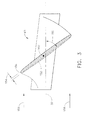
- FIG 3 is a cross-sectional view of an exemplary fan blade 40 taken along line 3-3 of Figure 1.
- Element 150 represents the stagger angle of blade 40 at the cross-section shown. Generally, angle 150 is dependent on a radial distance from axis 32 to the cross-section of interest. In the exemplary embodiment, angle 150 is measured between a chord 152 at the given cross section and fan axis 32.
- a thickness 154 of blade 40 represents the blade thickness near a leading edge 156 of blade 40. Leading edge 156 is in relation to airflow 158 through fan 38.
- Each blade 40 includes a radial axis 160.
- Factors of blade design that may affect pure multiple tone noise may be, for example, but are not limited to, differences of angle 150 from blade-to-blade, differences of thickness 154 from blade-to-blade, differences in the curvature of the blade airfoil at respective sections from blade-to-blade, and variations of spacing between adjacent blades. By determining a mapping order of the blades into specific slots in the rotor that minimizes variation of the above factors between adjacent blades, multiple pure tones or buzzsaw noise may be reduced.
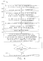
- Figure 4 is a flow diagram of an exemplary embodiment of a method 300 that may be used for ordering blades in a rotatable machine, such as, but not limited to, gas turbine engine 10 (shown in Figure 1).
- the machine is a gas turbine engine that includes a rotor, such as, but not limited to, rotor 11 (shown in Figure 1), that is rotatable about a longitudinal axis of symmetry of the engine.
- Method 300 includes receiving 302 at least one geometric parameter measurement of a plurality of blades in a row of blades.
- the fan blade geometric parameter may be based on a determination by an acoustics specialist and fan aerodynamics specialists relative to a customer specification.
- the geometric parameter may be any suitable geometric blade parameters, such as, but not limited to, a blade section stagger angle, a blade thickness, a blade chord length, a blade camber, a blade height, a blade tangential position, a blade axial position, and/or a blade radial position.
- the geometric parameter measurement may be received from a blade manufacturer and/or may be determined after the blade is received at a manufacturing facility.
- blade to blade variations in geometric parameters associated with the blades contributes to overall circumferential pressure differences of the row of blades, which manifests itself as buzzsaw noise.
- the blade section stagger angle may, in some embodiments, be defined as a rotation of at least a portion of a blade about a radial axis through a central region of the blade.
- the axis of stagger angle may be offset from a center radial axis of the blade, or may be coincident with the center radial axis.
- Blade thickness may refer to any thickness of the blade, such as, but not limited to, the thickness of the blade leading edge at a predetermined radial distance from the blade tip, the thickness of the blade trailing edge at a predetermined radial distance from the blade tip, the thickness of the blade at a predetermined intermediate point at a predetermined radial distance from the blade tip, the thickness of the blade leading edge at and/or adjacent a portion of the blade root, and/or the thickness of the blade trailing edge at and/or adjacent a portion of the blade root.
- the blade tangential position may, in some embodiments, be defined as a displacement of a blade tip or bending of the blade in a circumferential direction in a plane of rotation of the row of blades containing the blade.
- a blade tangential shift may be used to quantify an amount that a blade is offset from a radial orientation and may also describe a blade that is bowed in the plane of rotation of the row of blades containing the blade.
- an initial or starting blade map is determined 304.
- a blade map may indicate a specific slot for each blade that will be assembled into the rotor and may indicate an order of installation of the blades.
- the starting position may be a "virtual" position, in that the blades are simulated being installed using a computer model of the rotor and blades.
- Subsequent iterative maps of blade location may also be virtual maps until a predetermined endpoint is reached during iteration, when a final blade map may be displayed and/or printed.
- a maximum difference of one or more of the geometric parameter measurements between adjacent blades in the row of blades may be determined 306 from blade geometry data supplied by the blade manufacturer and/or may be determined by the manufacturing facility after receipt.
- a blade section stagger angle difference between adjacent blades may be determined by calculating a ratio of the inlet area to exit area for each set of adjacent blades installed in a starting position around the circumference of the rotor.
- the inlet area and/or exit area may be determined using a distance between adjacent blades at the same radial distance from the blade tip. Because at least some of the parameters that may be used to determine inlet area and exit area may be fixed, only a line distance may be used to determine ratio of the inlet area and outlet area.
- a vector sum of one or more of the geometric parameter measurements for a plurality of blades is also determined 308. For example, a vector sum of the blade section stagger angle of a plurality of blades and/or a vector sum of blade thicknesses of the plurality of blades may be determined.
- a plurality of moment weights of a plurality of blades in a row of blades may be determined 310.
- the plurality of moment weights may include, but are not limited to, at least two of a radial moment weight, an axial moment weight, and/or a tangential moment weight.
- the moment weights may be determined, for example, by horizontally supporting a blade by its root in a device designed to measure moment weight.
- a moment weight is based not only on a pan weight of the blade, but also is based on a distribution of the weight of the blade along a radial distance extending between the blade root to the blade tip.
- an uneven distribution of moment weight of each blade spaced about the rotor may affect a balance condition of the rotor.
- Corresponding moment weight vector sums of the rotor may also be determined 312 for each of the moment weights.
- Threshold values for the vector sums of the plurality moment weights of all the blades to be positioned on the rotor disk, the vector sum(s) of the geometric parameter measurement(s), and the maximum difference of the geometric parameter measurement(s) between adjacent blades are selected 314.
- the threshold values may be determined, for example, from an engineering or design requirement contained within a drawing or other technical or administrative document.
- the initial blade sequence is iteratively remapped 316 to reduce the maximum difference of the geometric parameter measurement(s) between adjacent blades, the vector sums of the plurality of moment weights, and the vector sum(s) of the geometric parameter measurement(s) to values that are less than the respective predetermined values.
- a computer including a processor and a program code segment configured to select and deselect blades may be utilized. Specifically, when blades are selected, a first blade may be selected for positioning in a specific slot based on the maximum difference of at least one geometric parameter measurement between adjacent blades in a row of blades, the vector sums of the plurality of moment weights, and/or the vector sum(s) of the geometric parameter measurement(s). Blades are iteratively arranged in an order that facilitates minimizing a combination of the vector sums of the plurality of moment weights, and the vector sum(s) of the geometric parameter measurement(s). During the process of minimizing, it may be necessary to completely reorder the selected blades.
- the computer system may then display the resultant blade map and generate a report detailing the selection process. Additionally, manual entry of blade parameters and recalculation of the blade map are supported.
- the initial blade map may be random, such that blades are assigned to slots in a random order. In various embodiments, the initial blade map is not random, but the initial blade map is determined based on a parameter that permits less iterations in the remapping process.
- the final blade sequence map may be displayed 320 and/or output.
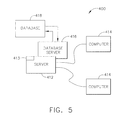
- FIG. 5 is a simplified block diagram of an exemplary embodiment of a blade mapping computer system 400.
- the term "computer” may include any processor-based or microprocessor-based system including systems using microcontrollers, reduced instruction set circuits (RISC), application specific integrated circuits (ASICs), logic circuits, and any other circuit or processor capable of executing the functions described herein.
- RISC reduced instruction set circuits
- ASICs application specific integrated circuits
- Computer system 400 includes a server system 412 including a disk storage unit 413 for data storage, and a plurality of client sub-systems, also referred to as client systems 414, connected to server system 412.
- client systems 414 are computers including a web browser, such that server system 412 is accessible to client systems 414 via the Internet.
- Client systems 414 are interconnected to the Internet through many interfaces including a network, such as a local area network (LAN) or a wide area network (WAN), dial-in-connections, cable modems and special high-speed ISDN lines.
- Client systems 414 could be any device capable of interconnecting to the Internet including a web-based phone, personal digital assistant (PDA), or other web-based connectable equipment.
- a database server 416 is connected to a database 418 containing information regarding engine components.
- centralized database 418 is stored on server system 412 and can be accessed by potential users at one of client systems 414 by logging onto server system 412 through one of client systems 414.
- database 418 is stored remotely from server system 412 and may be non-centralized.
- Example embodiments of systems and methods that facilitate reducing multiple pure tone noise in aircraft gas turbine engine fans are described above in detail.
- a technical effect of the systems and methods described herein includes reducing overall circumferential pressure differences between adjacent blades caused by blade to blade differences in blade geometric parameters that exceed a threshold value such that fan tonal noise is minimized, and therefore reducing aircraft passenger annoyance and community noise levels.
- Mapping specific blades into specific rotor slot such that blade to blade variations of a measured and/or a received geometric parameter are reduced facilitates reducing buzzsaw noise that is caused by the pressure oscillations caused by the blade to blade geometric variations between adjacent blades.
- the above-described blade mapping system is a cost-effective and highly reliable method and system that may be used for determining a blade map that reduces the corresponding vector sums of a plurality moment weights of all the blades to be positioned on the rotor disk, the vector sum(s) of one or more geometric parameter measurements, and the maximum difference of one or more geometric parameter measurement(s) between adjacent blades to a value that is less than a predetermined threshold. Accordingly, the blade mapping method and system facilitates assembly, operation, and maintenance of machines, and in particular gas turbine engines, in a cost-effective and reliable manner.
- blade mapping method and system components are described above in detail.
- the components are not limited to the specific embodiments described herein, but rather, components of each system may be utilized independently and separately from other components described herein.
- Each blade mapping system component can also be used in combination with other blade mapping system components.
Landscapes
- Engineering & Computer Science (AREA)
- Mechanical Engineering (AREA)
- General Engineering & Computer Science (AREA)
- Structures Of Non-Positive Displacement Pumps (AREA)
- Turbine Rotor Nozzle Sealing (AREA)
Abstract
Description
- This invention relates generally to gas turbine engines, and more specifically to methods and systems for ordering blades on a rotor of a rotatable machines.
- Gas turbines are used in different operating environments, such as, to provide propulsion for aircraft and/or to produce power in both land-based and sea-borne power systems. At least some known gas turbine engines include a core engine having, in serial flow arrangement, a fan assembly and a high pressure compressor that compress airflow entering the engine. A combustor ignites a fuel-air mixture that is then channeled through a turbine nozzle assembly towards high and low pressure turbines. The turbines each include a plurality of rotor blades that extract rotational energy from airflow exiting the combustor.
- At least some known turbofan gas turbine engines include a fan assembly that includes a plurality of fan blades extending radially outwardly therefrom. These blades may operate with a relative blade tip Mach number in the transonic regime and may be subject to an operating characteristic called multiple-pure-tone (MPT) noise, sometimes referred to as buzzsaw noise. Buzzsaw noise may occur if at least some blades are oriented differently relative to other blades extending around the circumference of the fan case. Moreover, such noise may occur if blade-to-blade geometry variations exist within the fan and/or if flowfield disturbances are present forward of the fan inlet. Such flowfield disturbances may be caused by any number of factors including, but not limited to drain leakage, panel splice leakage, or other geometric nonuniformities. As a result, variations may exist within the fan assembly in the amplitude (strength) and/or spacing of the shockwaves originating from those portions of the blades that have sonic or supersonic velocities. Specifically, at axial locations close to the fan blades, the noise due to the shock waves is generally at multiples of the fan shaft per revolution frequency, which is the frequency with which one point on the shaft passes any particular fixed point as it rotates.
- Shock waves of different strengths based on the flowfield disturbances may propagate at different speeds. Accordingly, as the shock waves travel away from the blades, the noise at a blade passing frequency degenerates into a broad spectrum of lower frequency tones as the shock waves merge with each other. Such tones or buzzsaw noise tend to increase passenger annoyance and reduce passenger comfort, and may also adversely affect community noise levels. However, maintaining close manufacturing tolerances to minimize blade to blade orientation and/or geometry variations may be insufficiently capable of minimizing buzzsaw noise.
- In one aspect according to the present invention, a method of ordering blades in a set of blades to be mounted in a rotor of a rotatable machine is provided. The method includes receiving at least one geometric parameter measurement of each blade in a row of blades, determining a maximum difference of the at least one received geometric parameter measurement between adjacent blades in the row of blades, determining a vector sum of at least one of the received geometric parameter measurements, determining a plurality of moment weight vector sums of the rotor, and determining, using a computer, a sequence map of the plurality of blades using the maximum difference of the at least one geometric parameter measurement between adjacent blades in the row of blades, the vector sum of the at least one received geometric parameter measurement, and the plurality of moment weight vector sums.
- In another aspect, a rotor assembly includes a disk including a plurality of circumferentially-spaced blade root slots defined therein, and a plurality of blades, each blade including a root, a tip, and an airfoil therebetween. Each blade is positioned within a pre-determined slot based on a blade map wherein the blade map is generated by a computer system configured to receive at least one geometric parameter measurement of a plurality of blades in a row of blades, determine a maximum difference of the at least one received geometric parameter measurement between adjacent blades in the row of blades, determine a vector sum of at least one of the received geometric parameter measurements, determine a plurality of moment weight vector sums of the rotor, and determine a sequence map of each blade using the maximum difference of the at least one geometric parameter measurement between adjacent blades in the row of blades, the vector sum of the at least one received geometric parameter measurement, and the plurality of moment weight vector sum.
- In another aspect, a computer system includes a software code segment programmed to minimize imbalance in a bladed rotor wherein the code segment is configured to receive at least one geometric parameter measurement of a plurality of blades in a row of blades, determine a maximum difference of the at least one received geometric parameter measurements between adjacent blades in the row of blades, determine a vector sum of at least one of the received geometric parameter measurements, determine a plurality of moment weight vector sums of the rotor, and determine a sequence map of each blade using the maximum difference of the at least one geometric parameter measurement between adjacent blades in the row of blades, the vector sum of the at least one received geometric parameter measurement, and the plurality of moment weight vector sums.
- Various aspects and embodiments of the present invention will now be described in connection with the accompanying drawings, in which:
- Figure 1 is a schematic illustration of an exemplary gas turbine engine.
- Figure 2 is an exploded perspective view of an exemplary fan rotor assembly that may be used with, but is not limited to being used with, the gas turbine engine shown in Figure 1.
- Figure 3 is a cross-sectional view of an exemplary fan blade taken along line 3-3 shown in Figure 1.
- Figure 4 is a flow diagram of an exemplary embodiment of a method for ordering blades in a rotatable machine, such as, but not limited to, the gas turbine engine shown in Figure 1.
- Figure 5 is a simplified block diagram of an exemplary embodiment of a blade mapping computer system.
- Figure 1 is a schematic illustration of an exemplary
gas turbine engine 10 including a rotor 11 that includes a low-pressure compressor 12, a high-pressure compressor 14, and acombustor 16.Engine 10 also includes a high-pressure turbine 18, a low-pressure turbine 20, anexhaust frame 22 and acasing 24. Afirst shaft 26 couples low-pressure compressor 12 and low-pressure turbine 20, and asecond shaft 28 couples high-pressure compressor 14 and high-pressure turbine 18.Engine 10 has an axis ofsymmetry 32 extending from anupstream side 34 ofengine 10 aft to adownstream side 36 ofengine 10. Rotor 11 also includes afan 38, which includes at least one row of airfoil-shaped fan blades 40 attached to a hub member ordisk 42.Blades 40 are substantially identical with respect to each other, except that there are some small differences due to manufacturing tolerances.Blades 40 are coupled todisk 42 in a substantially equi-angularly spaced relationship to each other. In one embodiment, not necessarily illustrated in Figure 1,gas turbine engine 10 is a GE90 engine commercially available from General Electric Company, Cincinnati, Ohio. - In operation, air flows through low-
pressure compressor 12 and compressed air is supplied to high-pressure compressor 14. Highly compressed air is delivered tocombustor 16.Combustion gases 44 fromcombustor 16propel turbines High pressure turbine 18 rotatessecond shaft 28 andhigh pressure compressor 14, whilelow pressure turbine 20 rotatesfirst shaft 26 andlow pressure compressor 12 aboutaxis 32. During some engine operations, such as during takeoff operations and other operating periods when engine power output is relatively high,fan 38 rotates such that a radially outer portion ofblades 40 attains supersonic velocity. As a result, the supersonically rotating portions ofblades 40 may produce shockwaves, which may generate undesirable noise. The noise may be spread over a broad tonal range, from many multiples of blade passing frequency down to the disk rotational frequency. - Figure 2 is an exploded perspective view of an exemplary
fan rotor assembly 100 that may be used with, but is not limited to being used with, gas turbine engine 10 (shown in Figure 1). A plurality of circumferentially-spacedblades 40 are supported by rotor disk ordrum 42 through adovetail slot 104. Eachblade 40 includes anairfoil 106 that extends between adovetail root 108 and ablade tip 110 such that eachblade 40 is supported throughdovetail root 108 anddovetail slot 104 byrotor 42.Blade 40 is representative of the plurality of circumferentially-spacedblades 40 that are each mapped into aspecific slot 104 based on measured parameters ofblade 40. As used herein, mapping is defined as assigning a specific blade into a specific slot in the rotor using a physical parameter of the blade, or physical parameters of a plurality of blades to determine the assignment. In the exemplary embodiment, eachblade 40 includes acomposite airfoil 106 that includes a plurality of layered composite plies (not shown). More specifically, eachblade 40 includes a first plurality of structural and load carrying airfoil plies inairfoil 106 and a second plurality of root plies inroot 108. - Figure 3 is a cross-sectional view of an
exemplary fan blade 40 taken along line 3-3 of Figure 1.Element 150 represents the stagger angle ofblade 40 at the cross-section shown. Generally,angle 150 is dependent on a radial distance fromaxis 32 to the cross-section of interest. In the exemplary embodiment,angle 150 is measured between achord 152 at the given cross section andfan axis 32. Athickness 154 ofblade 40 represents the blade thickness near a leadingedge 156 ofblade 40.Leading edge 156 is in relation toairflow 158 throughfan 38. Eachblade 40 includes aradial axis 160. - Factors of blade design that may affect pure multiple tone noise may be, for example, but are not limited to, differences of
angle 150 from blade-to-blade, differences ofthickness 154 from blade-to-blade, differences in the curvature of the blade airfoil at respective sections from blade-to-blade, and variations of spacing between adjacent blades. By determining a mapping order of the blades into specific slots in the rotor that minimizes variation of the above factors between adjacent blades, multiple pure tones or buzzsaw noise may be reduced. - Figure 4 is a flow diagram of an exemplary embodiment of a
method 300 that may be used for ordering blades in a rotatable machine, such as, but not limited to, gas turbine engine 10 (shown in Figure 1). In the exemplary embodiment, the machine is a gas turbine engine that includes a rotor, such as, but not limited to, rotor 11 (shown in Figure 1), that is rotatable about a longitudinal axis of symmetry of the engine. -
Method 300 includes receiving 302 at least one geometric parameter measurement of a plurality of blades in a row of blades. The fan blade geometric parameter may be based on a determination by an acoustics specialist and fan aerodynamics specialists relative to a customer specification. The geometric parameter may be any suitable geometric blade parameters, such as, but not limited to, a blade section stagger angle, a blade thickness, a blade chord length, a blade camber, a blade height, a blade tangential position, a blade axial position, and/or a blade radial position. The geometric parameter measurement may be received from a blade manufacturer and/or may be determined after the blade is received at a manufacturing facility. Generally blade to blade variations in geometric parameters associated with the blades contributes to overall circumferential pressure differences of the row of blades, which manifests itself as buzzsaw noise. - The blade section stagger angle may, in some embodiments, be defined as a rotation of at least a portion of a blade about a radial axis through a central region of the blade. The axis of stagger angle may be offset from a center radial axis of the blade, or may be coincident with the center radial axis. Blade thickness may refer to any thickness of the blade, such as, but not limited to, the thickness of the blade leading edge at a predetermined radial distance from the blade tip, the thickness of the blade trailing edge at a predetermined radial distance from the blade tip, the thickness of the blade at a predetermined intermediate point at a predetermined radial distance from the blade tip, the thickness of the blade leading edge at and/or adjacent a portion of the blade root, and/or the thickness of the blade trailing edge at and/or adjacent a portion of the blade root.
- The blade tangential position may, in some embodiments, be defined as a displacement of a blade tip or bending of the blade in a circumferential direction in a plane of rotation of the row of blades containing the blade. A blade tangential shift may be used to quantify an amount that a blade is offset from a radial orientation and may also describe a blade that is bowed in the plane of rotation of the row of blades containing the blade.
- Prior to positioning blades onto the rotor disk, an initial or starting blade map is determined 304. A blade map may indicate a specific slot for each blade that will be assembled into the rotor and may indicate an order of installation of the blades. The starting position may be a "virtual" position, in that the blades are simulated being installed using a computer model of the rotor and blades. Subsequent iterative maps of blade location may also be virtual maps until a predetermined endpoint is reached during iteration, when a final blade map may be displayed and/or printed.
- A maximum difference of one or more of the geometric parameter measurements between adjacent blades in the row of blades may be determined 306 from blade geometry data supplied by the blade manufacturer and/or may be determined by the manufacturing facility after receipt.
- For example, a blade section stagger angle difference between adjacent blades may be determined by calculating a ratio of the inlet area to exit area for each set of adjacent blades installed in a starting position around the circumference of the rotor. The inlet area and/or exit area may be determined using a distance between adjacent blades at the same radial distance from the blade tip. Because at least some of the parameters that may be used to determine inlet area and exit area may be fixed, only a line distance may be used to determine ratio of the inlet area and outlet area.
- A vector sum of one or more of the geometric parameter measurements for a plurality of blades is also determined 308. For example, a vector sum of the blade section stagger angle of a plurality of blades and/or a vector sum of blade thicknesses of the plurality of blades may be determined. A plurality of moment weights of a plurality of blades in a row of blades may be determined 310. The plurality of moment weights may include, but are not limited to, at least two of a radial moment weight, an axial moment weight, and/or a tangential moment weight. The moment weights may be determined, for example, by horizontally supporting a blade by its root in a device designed to measure moment weight. A moment weight is based not only on a pan weight of the blade, but also is based on a distribution of the weight of the blade along a radial distance extending between the blade root to the blade tip. In a rotating machine, an uneven distribution of moment weight of each blade spaced about the rotor may affect a balance condition of the rotor. Corresponding moment weight vector sums of the rotor may also be determined 312 for each of the moment weights.
- Threshold values for the vector sums of the plurality moment weights of all the blades to be positioned on the rotor disk, the vector sum(s) of the geometric parameter measurement(s), and the maximum difference of the geometric parameter measurement(s) between adjacent blades are selected 314. The threshold values may be determined, for example, from an engineering or design requirement contained within a drawing or other technical or administrative document. The initial blade sequence is iteratively remapped 316 to reduce the maximum difference of the geometric parameter measurement(s) between adjacent blades, the vector sums of the plurality of moment weights, and the vector sum(s) of the geometric parameter measurement(s) to values that are less than the respective predetermined values. To determine a mapping order, a computer including a processor and a program code segment configured to select and deselect blades may be utilized. Specifically, when blades are selected, a first blade may be selected for positioning in a specific slot based on the maximum difference of at least one geometric parameter measurement between adjacent blades in a row of blades, the vector sums of the plurality of moment weights, and/or the vector sum(s) of the geometric parameter measurement(s). Blades are iteratively arranged in an order that facilitates minimizing a combination of the vector sums of the plurality of moment weights, and the vector sum(s) of the geometric parameter measurement(s). During the process of minimizing, it may be necessary to completely reorder the selected blades. The computer system may then display the resultant blade map and generate a report detailing the selection process. Additionally, manual entry of blade parameters and recalculation of the blade map are supported. The initial blade map may be random, such that blades are assigned to slots in a random order. In various embodiments, the initial blade map is not random, but the initial blade map is determined based on a parameter that permits less iterations in the remapping process.
- When the vector sums of the plurality of moment weights of all the blades to be positioned on the rotor disk, the vector sum(s) of the geometric parameter measurement(s), and the maximum difference of the geometric parameter measurement(s) between adjacent blades are reduced 318 to values that are less than the respective predetermined values, the final blade sequence map may be displayed 320 and/or output.
- Figure 5 is a simplified block diagram of an exemplary embodiment of a blade
mapping computer system 400. As used herein, the term "computer" may include any processor-based or microprocessor-based system including systems using microcontrollers, reduced instruction set circuits (RISC), application specific integrated circuits (ASICs), logic circuits, and any other circuit or processor capable of executing the functions described herein. The above examples are exemplary only, and are thus not intended to limit in any way the definition and/or meaning of the term "computer."Computer system 400 includes aserver system 412 including adisk storage unit 413 for data storage, and a plurality of client sub-systems, also referred to asclient systems 414, connected toserver system 412. In one embodiment,client systems 414 are computers including a web browser, such thatserver system 412 is accessible toclient systems 414 via the Internet.Client systems 414 are interconnected to the Internet through many interfaces including a network, such as a local area network (LAN) or a wide area network (WAN), dial-in-connections, cable modems and special high-speed ISDN lines.Client systems 414 could be any device capable of interconnecting to the Internet including a web-based phone, personal digital assistant (PDA), or other web-based connectable equipment. Adatabase server 416 is connected to adatabase 418 containing information regarding engine components. In one embodiment,centralized database 418 is stored onserver system 412 and can be accessed by potential users at one ofclient systems 414 by logging ontoserver system 412 through one ofclient systems 414. In analternative embodiment database 418 is stored remotely fromserver system 412 and may be non-centralized. - Example embodiments of systems and methods that facilitate reducing multiple pure tone noise in aircraft gas turbine engine fans are described above in detail. A technical effect of the systems and methods described herein includes reducing overall circumferential pressure differences between adjacent blades caused by blade to blade differences in blade geometric parameters that exceed a threshold value such that fan tonal noise is minimized, and therefore reducing aircraft passenger annoyance and community noise levels.
- Mapping specific blades into specific rotor slot such that blade to blade variations of a measured and/or a received geometric parameter are reduced facilitates reducing buzzsaw noise that is caused by the pressure oscillations caused by the blade to blade geometric variations between adjacent blades.
- The above-described blade mapping system is a cost-effective and highly reliable method and system that may be used for determining a blade map that reduces the corresponding vector sums of a plurality moment weights of all the blades to be positioned on the rotor disk, the vector sum(s) of one or more geometric parameter measurements, and the maximum difference of one or more geometric parameter measurement(s) between adjacent blades to a value that is less than a predetermined threshold. Accordingly, the blade mapping method and system facilitates assembly, operation, and maintenance of machines, and in particular gas turbine engines, in a cost-effective and reliable manner.
- Exemplary embodiments of blade mapping method and system components are described above in detail. The components are not limited to the specific embodiments described herein, but rather, components of each system may be utilized independently and separately from other components described herein. Each blade mapping system component can also be used in combination with other blade mapping system components.
- While the invention has been described in terms of various specific embodiments, those skilled in the art will recognize that the invention can be practiced with modification within the spirit and scope of the claims.
Claims (10)
- A rotor assembly (100) comprising:a disk (42) comprising a plurality of circumferentially-spaced blade root slots defined therein; anda plurality of blades (40), each said blade comprising a root (108), a tip (110), and an airfoil (106) therebetween, each said blade positioned within a pre-determined slot (108) based on a blade map, said blade map generated by a computer system configured to:receive (302) at least one geometric parameter measurement of a plurality of blades in a row of blades;determine (306) a maximum difference between adjacent blades in the row of blades of at the least one received geometric parameter measurement;determine (308) a vector sum of the at least one received geometric parameter measurements;determine (310) a plurality of moment weight vector sums of the plurality of blades in the row of blades; anddetermine a sequence map of the plurality of blades using the maximum difference of the at least one geometric parameter measurement between adjacent blades in the row of blades, the vector sum of the at least one received geometric parameter measurement, and the plurality of moment weight vector sums.
- A rotor assembly (100) in accordance with Claim 1 wherein said computer system (400) is further configured to iteratively remap the sequence of the blades (40) to reduce the maximum difference of the at least one geometric parameter measurement between adjacent blades in a row of blades, the vector sum of the at least one received geometric parameter measurement, and the plurality of moment weight vector sums to a value less than a respective predetermined value.
- A rotor assembly (100) in accordance with Claim 1 or Claim 2 wherein said plurality of blades (40) are composite fan blades.
- A rotor assembly (100) in accordance with any preceding Claim wherein said computer system (400) is further configured to determine a maximum difference of at least one of a blade section stagger angle (150), a blade thickness (154), a blade chord length (152), a blade camber, a blade height, a blade tangential position, a blade axial position, and a blade radial position between the adjacent blades (40).
- A rotor assembly (100) in accordance with any preceding Claim wherein said computer system (400) is further configured to determine a vector sum of at least one of a blade section stagger angle (150), a blade thickness (154), a blade chord length (152), a blade camber, a blade height, a blade tangential position, a blade axial position, and a blade radial position of each blade in the row of blades (40).
- A rotor assembly (100) in accordance with any preceding Claim wherein said computer system (400) is further configured to determine at least two of a radial moment weight vector sum of the rotor (11), an axial moment weight vector sum of the rotor, and a tangential moment weight of the rotor.
- A computer system (400) comprising a software code segment programmed to minimize imbalance in a bladed rotor (11), said code segment configured to:receive (302) at least one geometric parameter measurement of a plurality of blades blade in a row of blades;determine (306) a maximum difference between adjacent blades in the row of blades of the at least one received geometric parameter measurement;determine (308) a vector sum of at least one of the received geometric parameter measurements;determine (310) a plurality of moment weight vector sums of the plurality of blades blade in the row of blades; anddetermine a sequence map of the plurality of blades using the maximum difference of the at least one geometric parameter measurement between adjacent blades in the row of blades, the vector sum of the at least one received geometric parameter measurement, and the plurality of moment weight vector sums.
- A computer system (400) in accordance with Claim 7 wherein said software code segment is configured to iteratively remap the sequence of the blades (40) to facilitate reducing the maximum difference of the at least one geometric parameter measurement between adjacent blades in the row of blades, the vector sum of the at least one received geometric parameter measurement, and the plurality of moment weight vector sums to a value less than a predetermined value.
- A computer system (400) in accordance with Claim 7 or Claim 8 wherein said software code segment is configured to determine a maximum difference of at least one of a blade section stagger angle (150), a blade thickness (154), a blade chord length (152), a blade camber, a blade height, a blade tangential position, a blade axial position, and a blade radial position between the adjacent blades (40).
- A computer system (400) in accordance with any one of Claims 7 to 9 wherein said software code segment is configured to determine a vector sum of at least one of a blade section stagger angle (150), a blade thickness (154), a blade chord length (152), a blade camber, a blade height, a blade tangential position, a blade axial position, and a blade radial position of each blade in the row of blades (40).
Applications Claiming Priority (1)
| Application Number | Priority Date | Filing Date | Title |
|---|---|---|---|
| US11/461,123 US7497662B2 (en) | 2006-07-31 | 2006-07-31 | Methods and systems for assembling rotatable machines |
Publications (3)
| Publication Number | Publication Date |
|---|---|
| EP1884624A2 true EP1884624A2 (en) | 2008-02-06 |
| EP1884624A3 EP1884624A3 (en) | 2012-10-24 |
| EP1884624B1 EP1884624B1 (en) | 2014-03-05 |
Family
ID=38370741
Family Applications (1)
| Application Number | Title | Priority Date | Filing Date |
|---|---|---|---|
| EP07112070.3A Ceased EP1884624B1 (en) | 2006-07-31 | 2007-07-09 | Method for ordering blades on a rotor of a turbomachine |
Country Status (3)
| Country | Link |
|---|---|
| US (1) | US7497662B2 (en) |
| EP (1) | EP1884624B1 (en) |
| JP (1) | JP4846667B2 (en) |
Cited By (7)
| Publication number | Priority date | Publication date | Assignee | Title |
|---|---|---|---|---|
| FR3037168A1 (en) * | 2015-06-08 | 2016-12-09 | Snecma | METHOD FOR SIMULATION OF AUB DISTRIBUTION ON A TURBOMACHINE DISK |
| EP3572620A1 (en) * | 2018-05-25 | 2019-11-27 | Rolls-Royce plc | Rotor blade arrangement |
| EP3572621A1 (en) * | 2018-05-25 | 2019-11-27 | Rolls-Royce plc | Rotor blade arrangement |
| EP3572619A1 (en) * | 2018-05-25 | 2019-11-27 | Rolls-Royce plc | Rotor blade arrangement |
| EP3667021A3 (en) * | 2018-12-07 | 2020-08-26 | United Technologies Corporation | Determining a moment weight of a component based on measured surface geometry/solid model of the component |
| US11047244B2 (en) | 2018-11-12 | 2021-06-29 | Rolls-Royce Plc | Rotor blade arrangement |
| FR3124216A1 (en) * | 2021-06-21 | 2022-12-23 | Safran Aircraft Engines | FAN BLADE BALANCING PROCEDURE WITH TRAILING EDGE MACHINING |
Families Citing this family (34)
| Publication number | Priority date | Publication date | Assignee | Title |
|---|---|---|---|---|
| US8180596B2 (en) * | 2004-07-13 | 2012-05-15 | General Electric Company | Methods and apparatus for assembling rotatable machines |
| US9291059B2 (en) * | 2009-12-23 | 2016-03-22 | Alstom Technology Ltd. | Airfoil for a compressor blade |
| CN102465825B (en) * | 2010-10-31 | 2016-08-03 | 江苏神州新能源电力有限公司 | A kind of blade screw-free fixing device for wind power generator |
| US8790067B2 (en) | 2011-04-27 | 2014-07-29 | United Technologies Corporation | Blade clearance control using high-CTE and low-CTE ring members |
| US8864492B2 (en) | 2011-06-23 | 2014-10-21 | United Technologies Corporation | Reverse flow combustor duct attachment |
| US8739547B2 (en) | 2011-06-23 | 2014-06-03 | United Technologies Corporation | Gas turbine engine joint having a metallic member, a CMC member, and a ceramic key |
| US9115649B2 (en) | 2011-07-05 | 2015-08-25 | United Technologies Corporation | Fan stagger angle for dirt rejection |
| US9335051B2 (en) | 2011-07-13 | 2016-05-10 | United Technologies Corporation | Ceramic matrix composite combustor vane ring assembly |
| US8920127B2 (en) | 2011-07-18 | 2014-12-30 | United Technologies Corporation | Turbine rotor non-metallic blade attachment |
| GB2513884B (en) | 2013-05-08 | 2015-06-17 | Univ Bristol | Method and apparatus for producing an acoustic field |
| GB2530036A (en) | 2014-09-09 | 2016-03-16 | Ultrahaptics Ltd | Method and apparatus for modulating haptic feedback |
| CN107534810B (en) | 2015-02-20 | 2019-12-20 | 超级触觉资讯处理有限公司 | Method for providing improved haptic feedback |
| FR3037111B1 (en) | 2015-06-08 | 2017-05-19 | Snecma | PROCESS FOR MANUFACTURING TURBOMACHINE BLOWER WITH REDUCED NOISE LEVEL AT MULTIPLE ROTATION FREQUENCIES OF TURBOMACHINE |
| US10818162B2 (en) | 2015-07-16 | 2020-10-27 | Ultrahaptics Ip Ltd | Calibration techniques in haptic systems |
| US10268275B2 (en) | 2016-08-03 | 2019-04-23 | Ultrahaptics Ip Ltd | Three-dimensional perceptions in haptic systems |
| US10943578B2 (en) | 2016-12-13 | 2021-03-09 | Ultrahaptics Ip Ltd | Driving techniques for phased-array systems |
| US11531395B2 (en) | 2017-11-26 | 2022-12-20 | Ultrahaptics Ip Ltd | Haptic effects from focused acoustic fields |
| WO2019122916A1 (en) | 2017-12-22 | 2019-06-27 | Ultrahaptics Limited | Minimizing unwanted responses in haptic systems |
| EP3729417B1 (en) | 2017-12-22 | 2025-09-10 | Ultrahaptics Ip Ltd | Tracking in haptic systems |
| SG11202010752VA (en) | 2018-05-02 | 2020-11-27 | Ultrahaptics Ip Ltd | Blocking plate structure for improved acoustic transmission efficiency |
| US11755791B2 (en) * | 2018-07-03 | 2023-09-12 | Rtx Corporation | Aircraft component qualification system and process |
| US11098951B2 (en) * | 2018-09-09 | 2021-08-24 | Ultrahaptics Ip Ltd | Ultrasonic-assisted liquid manipulation |
| US12373033B2 (en) | 2019-01-04 | 2025-07-29 | Ultrahaptics Ip Ltd | Mid-air haptic textures |
| US11447271B2 (en) * | 2019-04-05 | 2022-09-20 | Raytheon Technologies Corporation | Aircraft component repair scheduling system and process |
| US11842517B2 (en) | 2019-04-12 | 2023-12-12 | Ultrahaptics Ip Ltd | Using iterative 3D-model fitting for domain adaptation of a hand-pose-estimation neural network |
| CN114631139A (en) | 2019-10-13 | 2022-06-14 | 超飞跃有限公司 | Dynamic capping with virtual microphones |
| US11374586B2 (en) | 2019-10-13 | 2022-06-28 | Ultraleap Limited | Reducing harmonic distortion by dithering |
| US11715453B2 (en) | 2019-12-25 | 2023-08-01 | Ultraleap Limited | Acoustic transducer structures |
| DE102020003254A1 (en) | 2020-05-29 | 2021-12-02 | Rolls-Royce Deutschland Ltd & Co Kg | Method and control device for manufacturing a multi-part rotor of a gas turbine engine |
| US11816267B2 (en) | 2020-06-23 | 2023-11-14 | Ultraleap Limited | Features of airborne ultrasonic fields |
| US11886639B2 (en) | 2020-09-17 | 2024-01-30 | Ultraleap Limited | Ultrahapticons |
| US12517585B2 (en) | 2021-07-15 | 2026-01-06 | Ultraleap Limited | Control point manipulation techniques in haptic systems |
| US20240230448A1 (en) * | 2023-01-06 | 2024-07-11 | Pratt & Whitney Canada Corp. | Computationally balancing a rotating structure |
| TWI904478B (en) * | 2023-09-23 | 2025-11-11 | 台灣電力股份有限公司 | Automatic Sequencing System and Method for Driven Wheel Blades |
Citations (1)
| Publication number | Priority date | Publication date | Assignee | Title |
|---|---|---|---|---|
| US20060013692A1 (en) | 2004-07-13 | 2006-01-19 | Henning Thomas R | Methods and apparatus for assembling rotatable machines |
Family Cites Families (6)
| Publication number | Priority date | Publication date | Assignee | Title |
|---|---|---|---|---|
| US3771922A (en) * | 1972-10-30 | 1973-11-13 | Mc Donnell Douglas Corp | Stabilized rotary blades |
| GB2054058B (en) * | 1979-06-16 | 1983-04-20 | Rolls Royce | Reducing rotor noise |
| US5966525A (en) * | 1997-04-09 | 1999-10-12 | United Technologies Corporation | Acoustically improved gas turbine blade array |
| FR2842571B1 (en) * | 2002-07-17 | 2004-10-15 | Snecma Moteurs | PROCESS FOR DISTRIBUTION OF TURBOMACHINE ROTOR BLADES |
| US6908285B2 (en) * | 2003-04-08 | 2005-06-21 | General Electric Company | Methods and apparatus for assembling rotatable machines |
| US7287958B2 (en) * | 2005-01-10 | 2007-10-30 | General Electric Company | Methods and apparatus for assembling rotatable machines |
-
2006
- 2006-07-31 US US11/461,123 patent/US7497662B2/en active Active
-
2007
- 2007-07-09 EP EP07112070.3A patent/EP1884624B1/en not_active Ceased
- 2007-07-27 JP JP2007195867A patent/JP4846667B2/en not_active Expired - Fee Related
Patent Citations (1)
| Publication number | Priority date | Publication date | Assignee | Title |
|---|---|---|---|---|
| US20060013692A1 (en) | 2004-07-13 | 2006-01-19 | Henning Thomas R | Methods and apparatus for assembling rotatable machines |
Cited By (13)
| Publication number | Priority date | Publication date | Assignee | Title |
|---|---|---|---|---|
| FR3037168A1 (en) * | 2015-06-08 | 2016-12-09 | Snecma | METHOD FOR SIMULATION OF AUB DISTRIBUTION ON A TURBOMACHINE DISK |
| US10989227B2 (en) | 2018-05-25 | 2021-04-27 | Rolls-Royce Plc | Rotor blade arrangement |
| EP3572621A1 (en) * | 2018-05-25 | 2019-11-27 | Rolls-Royce plc | Rotor blade arrangement |
| EP3572619A1 (en) * | 2018-05-25 | 2019-11-27 | Rolls-Royce plc | Rotor blade arrangement |
| US10954794B2 (en) | 2018-05-25 | 2021-03-23 | Rolls-Royce Plc | Rotor blade arrangement |
| EP3572620A1 (en) * | 2018-05-25 | 2019-11-27 | Rolls-Royce plc | Rotor blade arrangement |
| US11111816B2 (en) | 2018-05-25 | 2021-09-07 | Rolls-Royce Plc | Rotor blade arrangement |
| US11047244B2 (en) | 2018-11-12 | 2021-06-29 | Rolls-Royce Plc | Rotor blade arrangement |
| EP3667021A3 (en) * | 2018-12-07 | 2020-08-26 | United Technologies Corporation | Determining a moment weight of a component based on measured surface geometry/solid model of the component |
| EP4273369A3 (en) * | 2018-12-07 | 2023-11-15 | RTX Corporation | Determining a moment weight of a component based on measured surface geometry/solid model of the component |
| FR3124216A1 (en) * | 2021-06-21 | 2022-12-23 | Safran Aircraft Engines | FAN BLADE BALANCING PROCEDURE WITH TRAILING EDGE MACHINING |
| WO2022269173A1 (en) | 2021-06-21 | 2022-12-29 | Safran Aircraft Engines | Method for balancing fan blades with trailing edge machining |
| US12140045B2 (en) | 2021-06-21 | 2024-11-12 | Safran Aircraft Engines | Method for balancing fan vanes with trailing edge machining |
Also Published As
| Publication number | Publication date |
|---|---|
| EP1884624A3 (en) | 2012-10-24 |
| JP4846667B2 (en) | 2011-12-28 |
| US20080027686A1 (en) | 2008-01-31 |
| EP1884624B1 (en) | 2014-03-05 |
| JP2008032010A (en) | 2008-02-14 |
| US7497662B2 (en) | 2009-03-03 |
Similar Documents
| Publication | Publication Date | Title |
|---|---|---|
| EP1884624B1 (en) | Method for ordering blades on a rotor of a turbomachine | |
| US7090464B2 (en) | Methods and apparatus for assembling rotatable machines | |
| US8180596B2 (en) | Methods and apparatus for assembling rotatable machines | |
| US6908285B2 (en) | Methods and apparatus for assembling rotatable machines | |
| US7572101B2 (en) | Methods and apparatus for assembling rotatable machines | |
| CN111173572A (en) | Rotor blade arrangement | |
| Ikeguchi et al. | Design and development of a 14-stage axial compressor for industrial gas turbine | |
| US20170122336A1 (en) | Gas turbine engine airfoil | |
| Gunn et al. | Non-axisymmetric stator design for boundary layer ingesting fans | |
| US7287958B2 (en) | Methods and apparatus for assembling rotatable machines | |
| Larosiliere et al. | Aerodynamic design study of advanced multistage axial compressor | |
| Blaha et al. | Numerical investigation of the flow in an aft-swept transonic compressor rotor | |
| Manwaring et al. | Inlet distortion generated periodic aerodynamic rotor response | |
| Benvenuti | Design and test of a new axial compressor for the Nuovo Pignone Heavy-Duty gas turbines | |
| Calvert et al. | Performance of a highly-loaded HP compressor | |
| US20180089361A1 (en) | Method for Scaling Turbomachine Airfoils | |
| Sehra et al. | Design of a high-performance axial compressor for utility gas turbine | |
| Pankov et al. | Computational and experimental studies of model fans for advanced turbofan engines | |
| Pullan et al. | The Influence of Sweep on Axial Flow Turbine Aerodynamics at Mid-Span | |
| Evans et al. | Clearance sensitivity mitigation in small core compressors | |
| Cherry et al. | The aerodynamic design and performance of the NASA/GE e3 low pressure turbine | |
| Bakir et al. | Latest developments in automotive engine cooling fan systems rotor-stator interactions | |
| Duncombe | Aerodynamic design of axial flow turbines | |
| US10711623B1 (en) | Gas turbine engine airfoil frequency design | |
| Benvenuti | Design and Test of a New Axial Compressor for the Nuovo Pignone Heavy Duty Gas Turbines |
Legal Events
| Date | Code | Title | Description |
|---|---|---|---|
| PUAI | Public reference made under article 153(3) epc to a published international application that has entered the european phase |
Free format text: ORIGINAL CODE: 0009012 |
|
| AK | Designated contracting states |
Kind code of ref document: A2 Designated state(s): AT BE BG CH CY CZ DE DK EE ES FI FR GB GR HU IE IS IT LI LT LU LV MC MT NL PL PT RO SE SI SK TR |
|
| AX | Request for extension of the european patent |
Extension state: AL BA HR MK YU |
|
| PUAL | Search report despatched |
Free format text: ORIGINAL CODE: 0009013 |
|
| AK | Designated contracting states |
Kind code of ref document: A3 Designated state(s): AT BE BG CH CY CZ DE DK EE ES FI FR GB GR HU IE IS IT LI LT LU LV MC MT NL PL PT RO SE SI SK TR |
|
| AX | Request for extension of the european patent |
Extension state: AL BA HR MK RS |
|
| RIC1 | Information provided on ipc code assigned before grant |
Ipc: F01D 5/30 20060101AFI20120914BHEP Ipc: F01D 5/02 20060101ALI20120914BHEP |
|
| 17P | Request for examination filed |
Effective date: 20130424 |
|
| AKX | Designation fees paid |
Designated state(s): DE FR GB |
|
| GRAP | Despatch of communication of intention to grant a patent |
Free format text: ORIGINAL CODE: EPIDOSNIGR1 |
|
| INTG | Intention to grant announced |
Effective date: 20130917 |
|
| GRAS | Grant fee paid |
Free format text: ORIGINAL CODE: EPIDOSNIGR3 |
|
| GRAA | (expected) grant |
Free format text: ORIGINAL CODE: 0009210 |
|
| AK | Designated contracting states |
Kind code of ref document: B1 Designated state(s): DE FR GB |
|
| REG | Reference to a national code |
Ref country code: GB Ref legal event code: FG4D |
|
| REG | Reference to a national code |
Ref country code: DE Ref legal event code: R096 Ref document number: 602007035316 Country of ref document: DE Effective date: 20140417 |
|
| REG | Reference to a national code |
Ref country code: DE Ref legal event code: R097 Ref document number: 602007035316 Country of ref document: DE |
|
| PLBE | No opposition filed within time limit |
Free format text: ORIGINAL CODE: 0009261 |
|
| STAA | Information on the status of an ep patent application or granted ep patent |
Free format text: STATUS: NO OPPOSITION FILED WITHIN TIME LIMIT |
|
| 26N | No opposition filed |
Effective date: 20141208 |
|
| REG | Reference to a national code |
Ref country code: DE Ref legal event code: R097 Ref document number: 602007035316 Country of ref document: DE Effective date: 20141208 |
|
| REG | Reference to a national code |
Ref country code: FR Ref legal event code: PLFP Year of fee payment: 10 |
|
| REG | Reference to a national code |
Ref country code: FR Ref legal event code: PLFP Year of fee payment: 11 |
|
| PGFP | Annual fee paid to national office [announced via postgrant information from national office to epo] |
Ref country code: GB Payment date: 20170727 Year of fee payment: 11 Ref country code: FR Payment date: 20170726 Year of fee payment: 11 Ref country code: DE Payment date: 20170727 Year of fee payment: 11 |
|
| REG | Reference to a national code |
Ref country code: DE Ref legal event code: R119 Ref document number: 602007035316 Country of ref document: DE |
|
| GBPC | Gb: european patent ceased through non-payment of renewal fee |
Effective date: 20180709 |
|
| PG25 | Lapsed in a contracting state [announced via postgrant information from national office to epo] |
Ref country code: GB Free format text: LAPSE BECAUSE OF NON-PAYMENT OF DUE FEES Effective date: 20180709 Ref country code: FR Free format text: LAPSE BECAUSE OF NON-PAYMENT OF DUE FEES Effective date: 20180731 Ref country code: DE Free format text: LAPSE BECAUSE OF NON-PAYMENT OF DUE FEES Effective date: 20190201 |