EP1884465A2 - Air cycle for an aircraft environmental control system - Google Patents
Air cycle for an aircraft environmental control system Download PDFInfo
- Publication number
- EP1884465A2 EP1884465A2 EP07252858A EP07252858A EP1884465A2 EP 1884465 A2 EP1884465 A2 EP 1884465A2 EP 07252858 A EP07252858 A EP 07252858A EP 07252858 A EP07252858 A EP 07252858A EP 1884465 A2 EP1884465 A2 EP 1884465A2
- Authority
- EP
- European Patent Office
- Prior art keywords
- air
- heat exchanger
- diffuser
- diffuser plate
- turbine
- Prior art date
- Legal status (The legal status is an assumption and is not a legal conclusion. Google has not performed a legal analysis and makes no representation as to the accuracy of the status listed.)
- Withdrawn
Links
- 230000007613 environmental effect Effects 0.000 title claims abstract description 8
- 238000011144 upstream manufacturing Methods 0.000 claims description 5
- 239000007788 liquid Substances 0.000 abstract description 35
- 238000004806 packaging method and process Methods 0.000 abstract description 6
- 239000003570 air Substances 0.000 description 52
- XLYOFNOQVPJJNP-UHFFFAOYSA-N water Chemical group O XLYOFNOQVPJJNP-UHFFFAOYSA-N 0.000 description 9
- 239000002826 coolant Substances 0.000 description 7
- 238000001816 cooling Methods 0.000 description 3
- 102100025093 Zinc fingers and homeoboxes protein 2 Human genes 0.000 description 2
- 230000008901 benefit Effects 0.000 description 2
- 230000007423 decrease Effects 0.000 description 2
- 238000007710 freezing Methods 0.000 description 2
- 230000008014 freezing Effects 0.000 description 2
- 238000000034 method Methods 0.000 description 2
- 238000012986 modification Methods 0.000 description 2
- 230000004048 modification Effects 0.000 description 2
- 230000008569 process Effects 0.000 description 2
- 239000012080 ambient air Substances 0.000 description 1
- 230000001143 conditioned effect Effects 0.000 description 1
- 230000003247 decreasing effect Effects 0.000 description 1
- 230000003993 interaction Effects 0.000 description 1
- 238000012423 maintenance Methods 0.000 description 1
- 239000000203 mixture Substances 0.000 description 1
- 230000007704 transition Effects 0.000 description 1
Images



Classifications
-
- B—PERFORMING OPERATIONS; TRANSPORTING
- B64—AIRCRAFT; AVIATION; COSMONAUTICS
- B64D—EQUIPMENT FOR FITTING IN OR TO AIRCRAFT; FLIGHT SUITS; PARACHUTES; ARRANGEMENT OR MOUNTING OF POWER PLANTS OR PROPULSION TRANSMISSIONS IN AIRCRAFT
- B64D13/00—Arrangements or adaptations of air-treatment apparatus for aircraft crew or passengers, or freight space
- B64D13/06—Arrangements or adaptations of air-treatment apparatus for aircraft crew or passengers, or freight space the air being conditioned
-
- F—MECHANICAL ENGINEERING; LIGHTING; HEATING; WEAPONS; BLASTING
- F28—HEAT EXCHANGE IN GENERAL
- F28F—DETAILS OF HEAT-EXCHANGE AND HEAT-TRANSFER APPARATUS, OF GENERAL APPLICATION
- F28F9/00—Casings; Header boxes; Auxiliary supports for elements; Auxiliary members within casings
- F28F9/02—Header boxes; End plates
- F28F9/026—Header boxes; End plates with static flow control means, e.g. with means for uniformly distributing heat exchange media into conduits
- F28F9/0265—Header boxes; End plates with static flow control means, e.g. with means for uniformly distributing heat exchange media into conduits by using guiding means or impingement means inside the header box
-
- F—MECHANICAL ENGINEERING; LIGHTING; HEATING; WEAPONS; BLASTING
- F28—HEAT EXCHANGE IN GENERAL
- F28F—DETAILS OF HEAT-EXCHANGE AND HEAT-TRANSFER APPARATUS, OF GENERAL APPLICATION
- F28F9/00—Casings; Header boxes; Auxiliary supports for elements; Auxiliary members within casings
- F28F9/02—Header boxes; End plates
- F28F9/026—Header boxes; End plates with static flow control means, e.g. with means for uniformly distributing heat exchange media into conduits
- F28F9/0265—Header boxes; End plates with static flow control means, e.g. with means for uniformly distributing heat exchange media into conduits by using guiding means or impingement means inside the header box
- F28F9/0268—Header boxes; End plates with static flow control means, e.g. with means for uniformly distributing heat exchange media into conduits by using guiding means or impingement means inside the header box in the form of multiple deflectors for channeling the heat exchange medium
-
- B—PERFORMING OPERATIONS; TRANSPORTING
- B64—AIRCRAFT; AVIATION; COSMONAUTICS
- B64D—EQUIPMENT FOR FITTING IN OR TO AIRCRAFT; FLIGHT SUITS; PARACHUTES; ARRANGEMENT OR MOUNTING OF POWER PLANTS OR PROPULSION TRANSMISSIONS IN AIRCRAFT
- B64D13/00—Arrangements or adaptations of air-treatment apparatus for aircraft crew or passengers, or freight space
- B64D13/06—Arrangements or adaptations of air-treatment apparatus for aircraft crew or passengers, or freight space the air being conditioned
- B64D2013/0603—Environmental Control Systems
- B64D2013/0614—Environmental Control Systems with subsystems for cooling avionics
-
- B—PERFORMING OPERATIONS; TRANSPORTING
- B64—AIRCRAFT; AVIATION; COSMONAUTICS
- B64D—EQUIPMENT FOR FITTING IN OR TO AIRCRAFT; FLIGHT SUITS; PARACHUTES; ARRANGEMENT OR MOUNTING OF POWER PLANTS OR PROPULSION TRANSMISSIONS IN AIRCRAFT
- B64D13/00—Arrangements or adaptations of air-treatment apparatus for aircraft crew or passengers, or freight space
- B64D13/06—Arrangements or adaptations of air-treatment apparatus for aircraft crew or passengers, or freight space the air being conditioned
- B64D2013/0603—Environmental Control Systems
- B64D2013/0674—Environmental Control Systems comprising liquid subsystems
-
- Y—GENERAL TAGGING OF NEW TECHNOLOGICAL DEVELOPMENTS; GENERAL TAGGING OF CROSS-SECTIONAL TECHNOLOGIES SPANNING OVER SEVERAL SECTIONS OF THE IPC; TECHNICAL SUBJECTS COVERED BY FORMER USPC CROSS-REFERENCE ART COLLECTIONS [XRACs] AND DIGESTS
- Y02—TECHNOLOGIES OR APPLICATIONS FOR MITIGATION OR ADAPTATION AGAINST CLIMATE CHANGE
- Y02T—CLIMATE CHANGE MITIGATION TECHNOLOGIES RELATED TO TRANSPORTATION
- Y02T50/00—Aeronautics or air transport
- Y02T50/40—Weight reduction
-
- Y—GENERAL TAGGING OF NEW TECHNOLOGICAL DEVELOPMENTS; GENERAL TAGGING OF CROSS-SECTIONAL TECHNOLOGIES SPANNING OVER SEVERAL SECTIONS OF THE IPC; TECHNICAL SUBJECTS COVERED BY FORMER USPC CROSS-REFERENCE ART COLLECTIONS [XRACs] AND DIGESTS
- Y02—TECHNOLOGIES OR APPLICATIONS FOR MITIGATION OR ADAPTATION AGAINST CLIMATE CHANGE
- Y02T—CLIMATE CHANGE MITIGATION TECHNOLOGIES RELATED TO TRANSPORTATION
- Y02T50/00—Aeronautics or air transport
- Y02T50/50—On board measures aiming to increase energy efficiency
Definitions
- the present invention relates to environmental control systems (ECSs), and more particularly to an air cycle machine (ACM) heat exchanger interface.
- ECSs environmental control systems
- ACM air cycle machine
- ECSs provide a supply of conditioned air to an enclosure, such as an aircraft cabin and cockpit.
- Conventional ECSs have utilized an air-to-air cycle cooling system which is in a heat exchange relationship with a liquid loop.
- the liquid loop typically cools other heat loads such as avionics packages. Interaction between the air and liquid subsystems may be relatively complex.
- the ACM communicates airflow from the turbine to the liquid-to-air heat exchanger through a diffuser.
- the diffuser requires gradual transitions from the circular turbine exit to the rectilinear heat exchanger inlet to minimize irrecoverable pressure losses and achieve effective flow distribution. Although effective, such an arrangement may require relatively significant packaging space.
- the ECS system provides an ACM mounted adjacent a heat exchanger through a diffuser that contains a diffuser plate.
- the diffuser plate receives airflow from the ACM which strikes the diffuser plate and flows radially outward and around the diffuser plate and into the heat exchanger.
- a diffuser plate outer periphery is shaped to assure minimal pressure loss and proper flow distribution into the air-liquid heat exchanger with significantly less packaging space relative to conventional ACM arrangements.
- the present invention therefore provides an ACM and diffuser heat exchanger interface which decreases packaging space therein.
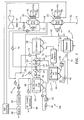
- FIG. 1 illustrates a general schematic view of a liquid-to-air cycle system or environmental control system (ECS) 10.
- the ECS 10 includes an air cycle subsystem 12 that is in a heat exchange relationship with a liquid cycle subsystem 14a, 14b. It should be understood that although two separate liquid subsystems are disclosed in the illustrative embodiment, a single substantially continuous subsystem will also benefit from the present invention.
- Bleed air 11 is preferably received from a gas turbine engine (illustrated schematically at 15).
- the bleed air 11 is sent through a primary heat exchanger 16 such that the bleed air 11 is in heat exchange relationship with RAM or ambient air.
- the primary heat exchanger 16 is preferably an air-to-air exchanger.
- the resulting cooler air is communicated through a passage 18 which communicates with a compressor 20 where the air is compressed to a high pressure.
- the compressor 20 is preferably located upon a common shaft with a first turbine 22 and a second turbine 24.
- the compressor 20 and turbines 22, 24 define an air cycle machine (ACM) 26.
- ACM air cycle machine
- Compressed air exits the compressor 20 through a passage 28 which communicates with a secondary heat exchanger 30.
- the secondary heat exchanger 30 is preferably an air-to-air exchanger which further cools the compressed air by heat exchange with a RAM air flow.
- Compressed, cooled and water vapor bearing air exits the secondary heat exchanger 30 and flows through a duct 32 which communicates with a reheater 34.
- the reheater 34 further cools the water vapor bearing air which exits the reheater 34 through a passage 36. Passage 36 communicates with a condenser 38 which further cools the water vapor bearing air by condensing and separating the water into a water extractor 40. As the water vapor bearing air is passed directly from the reheater 34 to the condenser 38, the water from the water vapor condenses relatively easily.
- Dehumidified air exits the extractor 40 and is communicated through a passage 42 to a first air-liquid heat exchanger 44.
- the first air-liquid heat exchanger 44 is part of the air cycle subsystem 12 and the liquid cycle subsystem 14a to form a heat exchange relationship therebetween. Moreover, moisture which may remain in the air is removed as the temperature of the air is increased by passage through the first air-liquid heat exchanger 44.
- the liquid cycle subsystem 14a is preferably a closed system and utilizes a liquid coolant, such as polyalphaolephin (PAO) which is cycled by a pump 46 or the like.
- the liquid coolant functions as a coolant medium for a heat load 48 and as a heat source for the dehumidified air which is passing through passage 42.
- the heat load 48 is typically an avionics subsystem which generates a rather large amount of heat--typically around 160 degrees Fahrenheit (70°C).
- the heat exchange process therein between the liquid coolant in the liquid cycle subsystem 14a and the air communicated through passage 42 cools the liquid, removes heat from the load 48, and heats the air exiting the first air-liquid heat exchanger 44.
- Dehumidified heated air exits the first air-liquid heat exchanger 44 through a passage 50 which communicates with the first turbine 22.
- the air is expanded through the first turbine of the ACM 26 between an inlet pressure of the first turbine 22 and an outlet pressure of the second turbine 24.
- the first turbine 22 also assists in condensing any water vapor which may still be in the air as a result of the air being expanded and thus cooled.
- the recovered heat from the first air-liquid heat exchanger 44 is used by the first turbine 22, for example, to increase its rotating speed, boost its pressure ratio, increase its power and increase the expansion of the reheated air. Further, the first turbine 22 is mechanically engaged to the compressor 20 and the second turbine 24. Thus, heat or energy absorbed by the first turbine 22 is further converted to useful energy by the compressor 20.
- the discharge pressure from the first turbine 22 is maintained at a discharge temperature just above freezing (mid-pressure) so that the first turbine 22 outlet air which passes through a passage 52 operates as a heat sink for the condenser 38 and the reheater 34. That heated air exits the reheater 34 through a passage 54 which communicates with the second turbine 24.
- the recovered heat from the condenser 38 and the reheater 34 is used by the second turbine 24, for example, to increase its rotating speed, boost its pressure ratio, increase its power and increase the expansion of the reheated air.
- the performance of both turbines 22, 24 is improved from otherwise wasted energy.
- the increased turbine cooling advantageously allows the minimization of size and/or weight of the heat exchangers.
- the air is expanded through the second turbine 24 of the ACM 26.
- the discharge pressure from the second turbine 24 is preferably maintained at a discharge temperature just below freezing.
- the second turbine 24 outlet air passes through a passage 56 which communicates with a second air-liquid heat exchanger 58.
- the second air-liquid heat exchanger 58 forms part of the air cycle subsystem 12 and the liquid cycle subsystem 14b to form a heat exchange relationship therebetween.
- the liquid cycle subsystem 14b is preferably a closed system as described above.
- the liquid coolant of the liquid cycle subsystem 14b is cycled by a pump 60 and functions as a coolant medium for a second heat load 62.
- An operating temperature of the second heat load 62 is preferably lower than the operating temperature of the first heat load 48, typically around 75 degrees Fahrenheit (24°C), but also cools other downstream heat loads. It should be understood that the operating temperatures of the heat loads are representative and other operating temperatures will also be applicable to the present invention.
- the heat exchange process therein between the liquid coolant in the liquid cycle subsystem 14b and the air communicated through passage 56 cools the liquid, removes heat from the load 62, and heats the air exiting the second air-liquid heat exchanger 58.
- the relatively warmer air exits second air-liquid heat exchanger 58 through a passage 64 which communicates with cockpit 66 and/or other air loads 68 to provide cooling air therefor.
- a temperature control passage 70, 72 communicates directly with bleed air 11 prior and/or subsequent to the primary heat exchanger 16.
- Control valves 74 are preferably located just downstream of the first turbine 22 and the second turbine 24, and just upstream of the cockpit 66 and/or the air loads 68 to allow warm air mixture therewith. Operation of such control valves may be implemented by a microprocessor based electronic control system.
- the primary heat exchanger 16 and the secondary heat exchanger 30 preferably include a respective primary RAM air fan (RAF) system 76 and a secondary RAM air fan (RAF) system 78.
- the RAFs 76, 78 are located downstream of the respective heat exchangers 16, 30 in the RAM exhaust (illustrated schematically by arrows Ep, Es) such that temperature rise across the RAFs 76, 78 will not affect ECS performance.
- Each RAF 76, 78 includes an electric motor 80,82 such that each RAF 76, 78 is driven at a speed independent of the ACM 26 which reduces generated noise and increases overall operating efficiency.
- each RAF 76, 78 is driven by the independent RAF electric motors 80, 82 the RAF 76, 78 are preferably installed in the ECS systems 10 as self contained systems such as Line Replaceable Units (LRUs) which simplifies maintenance, improves reliability and performance while decreasing system weight.
- LRUs Line Replaceable Units
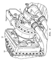
- the ACM 26 is mounted adjacent the air-liquid heat exchanger 58 through a diffuser 90. It should be understood that various mounting arrangements at various heat exchangers will be usable with the present invention.
- the diffuser 90 contains a diffuser plate 92.
- the diffuser plate 92 is preferably spaced away from an inner wall 94 of the diffuser 90 upstream of the heat exchanger 58 ( Figure 2).
- the diffuser plate 92 receives airflow from the ACM. The airflow strikes the diffuser plate 92 and flows radially outward and around the diffuser plate 92 and into the heat exchanger 58 ( Figure 4).
- the diffuser plate 92 includes a central spike 96 defined along a centerline C of the ACM outlet.
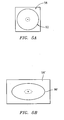
- a diffuser plate outer periphery 98 (also illustrated in Figure 4) is preferably shaped to assure minimal pressure loss and proper flow distribution into the air-liquid heat exchanger 58. It should be understood that although a generally circular outer periphery is preferred for a heat exchanger having a square cross-sectional profile (Figure 5A), other diffuser plate outer peripheries are preferred for heat exchangers having other cross-sectional profiles such as an oval outer periphery 98' for a rectangular non-square cross-sectional profile heat exchanger ( Figure 5B). It should be understood that other plate shapes appropriate for the heat exchanger cross-sectional profile will also be usable with the present invention.
- the diffuser arrangement of the present invention provides an ACM of significantly less packaging space relative to conventional ACM arrangements ( Figure 7).
Landscapes
- Engineering & Computer Science (AREA)
- Physics & Mathematics (AREA)
- Thermal Sciences (AREA)
- Mechanical Engineering (AREA)
- General Engineering & Computer Science (AREA)
- Health & Medical Sciences (AREA)
- General Health & Medical Sciences (AREA)
- Pulmonology (AREA)
- Aviation & Aerospace Engineering (AREA)
- Heat-Exchange Devices With Radiators And Conduit Assemblies (AREA)
- Structures Of Non-Positive Displacement Pumps (AREA)
Abstract
Description
- The present invention relates to environmental control systems (ECSs), and more particularly to an air cycle machine (ACM) heat exchanger interface.
- ECSs provide a supply of conditioned air to an enclosure, such as an aircraft cabin and cockpit. Conventional ECSs have utilized an air-to-air cycle cooling system which is in a heat exchange relationship with a liquid loop. The liquid loop typically cools other heat loads such as avionics packages. Interaction between the air and liquid subsystems may be relatively complex.
- The ACM communicates airflow from the turbine to the liquid-to-air heat exchanger through a diffuser. The diffuser requires gradual transitions from the circular turbine exit to the rectilinear heat exchanger inlet to minimize irrecoverable pressure losses and achieve effective flow distribution. Although effective, such an arrangement may require relatively significant packaging space.
- Accordingly, it is desirable to provide an ACM and diffuser heat exchanger interface which decreases packaging space therein.
- The ECS system according to the present invention provides an ACM mounted adjacent a heat exchanger through a diffuser that contains a diffuser plate. The diffuser plate receives airflow from the ACM which strikes the diffuser plate and flows radially outward and around the diffuser plate and into the heat exchanger. A diffuser plate outer periphery is shaped to assure minimal pressure loss and proper flow distribution into the air-liquid heat exchanger with significantly less packaging space relative to conventional ACM arrangements.
- The present invention therefore provides an ACM and diffuser heat exchanger interface which decreases packaging space therein.
- The various features and advantages of this invention will become apparent to those skilled in the art from the following detailed description of the currently preferred embodiment. The drawings that accompany the detailed description can be briefly described as follows:
- Figure 1 is a schematic representation of environmental control system according to the present invention;
- Figure 2 is a perspective view of an ACM radial diffuser arrangement;
- Figure 3 is a sectional view of an ACM radial diffuser arrangement;
- Figure 4 is a sectional view of an ACM radial diffuser showing airflow therethrough;
- Figures 5A and 5B are schematic views of an ACM radial diffuser plate shape relative a heat exchanger shape; and
- Figure 6 is a side view of the diffuser compared to a prior art diffuser of Figure 7.
- Figure 1 illustrates a general schematic view of a liquid-to-air cycle system or environmental control system (ECS) 10. The ECS 10 includes an
air cycle subsystem 12 that is in a heat exchange relationship with aliquid cycle subsystem - Bleed
air 11 is preferably received from a gas turbine engine (illustrated schematically at 15). Thebleed air 11 is sent through aprimary heat exchanger 16 such that thebleed air 11 is in heat exchange relationship with RAM or ambient air. Theprimary heat exchanger 16 is preferably an air-to-air exchanger. After thebleed air 11 is cooled in theprimary heat exchanger 16, the resulting cooler air is communicated through apassage 18 which communicates with acompressor 20 where the air is compressed to a high pressure. Thecompressor 20 is preferably located upon a common shaft with afirst turbine 22 and asecond turbine 24. Thecompressor 20 andturbines - Compressed air exits the
compressor 20 through apassage 28 which communicates with asecondary heat exchanger 30. Thesecondary heat exchanger 30 is preferably an air-to-air exchanger which further cools the compressed air by heat exchange with a RAM air flow. Compressed, cooled and water vapor bearing air exits thesecondary heat exchanger 30 and flows through aduct 32 which communicates with areheater 34. - The
reheater 34 further cools the water vapor bearing air which exits thereheater 34 through apassage 36.Passage 36 communicates with acondenser 38 which further cools the water vapor bearing air by condensing and separating the water into awater extractor 40. As the water vapor bearing air is passed directly from thereheater 34 to thecondenser 38, the water from the water vapor condenses relatively easily. - Dehumidified air exits the
extractor 40 and is communicated through apassage 42 to a first air-liquid heat exchanger 44. The first air-liquid heat exchanger 44 is part of theair cycle subsystem 12 and theliquid cycle subsystem 14a to form a heat exchange relationship therebetween. Moreover, moisture which may remain in the air is removed as the temperature of the air is increased by passage through the first air-liquid heat exchanger 44. - The
liquid cycle subsystem 14a is preferably a closed system and utilizes a liquid coolant, such as polyalphaolephin (PAO) which is cycled by apump 46 or the like. The liquid coolant functions as a coolant medium for aheat load 48 and as a heat source for the dehumidified air which is passing throughpassage 42. Theheat load 48 is typically an avionics subsystem which generates a rather large amount of heat--typically around 160 degrees Fahrenheit (70°C). The heat exchange process therein between the liquid coolant in theliquid cycle subsystem 14a and the air communicated throughpassage 42 cools the liquid, removes heat from theload 48, and heats the air exiting the first air-liquid heat exchanger 44. - Dehumidified heated air exits the first air-
liquid heat exchanger 44 through apassage 50 which communicates with thefirst turbine 22. The air is expanded through the first turbine of the ACM 26 between an inlet pressure of thefirst turbine 22 and an outlet pressure of thesecond turbine 24. Thefirst turbine 22 also assists in condensing any water vapor which may still be in the air as a result of the air being expanded and thus cooled. - The recovered heat from the first air-
liquid heat exchanger 44 is used by thefirst turbine 22, for example, to increase its rotating speed, boost its pressure ratio, increase its power and increase the expansion of the reheated air. Further, thefirst turbine 22 is mechanically engaged to thecompressor 20 and thesecond turbine 24. Thus, heat or energy absorbed by thefirst turbine 22 is further converted to useful energy by thecompressor 20. - The discharge pressure from the
first turbine 22 is maintained at a discharge temperature just above freezing (mid-pressure) so that thefirst turbine 22 outlet air which passes through apassage 52 operates as a heat sink for thecondenser 38 and thereheater 34. That heated air exits thereheater 34 through apassage 54 which communicates with thesecond turbine 24. The recovered heat from thecondenser 38 and thereheater 34 is used by thesecond turbine 24, for example, to increase its rotating speed, boost its pressure ratio, increase its power and increase the expansion of the reheated air. Thus, the performance of bothturbines - The air is expanded through the
second turbine 24 of the ACM 26. The discharge pressure from thesecond turbine 24 is preferably maintained at a discharge temperature just below freezing. Thesecond turbine 24 outlet air passes through apassage 56 which communicates with a second air-liquid heat exchanger 58. The second air-liquid heat exchanger 58 forms part of theair cycle subsystem 12 and theliquid cycle subsystem 14b to form a heat exchange relationship therebetween. - The
liquid cycle subsystem 14b is preferably a closed system as described above. The liquid coolant of theliquid cycle subsystem 14b is cycled by apump 60 and functions as a coolant medium for asecond heat load 62. An operating temperature of thesecond heat load 62 is preferably lower than the operating temperature of thefirst heat load 48, typically around 75 degrees Fahrenheit (24°C), but also cools other downstream heat loads. It should be understood that the operating temperatures of the heat loads are representative and other operating temperatures will also be applicable to the present invention. - The heat exchange process therein between the liquid coolant in the
liquid cycle subsystem 14b and the air communicated throughpassage 56 cools the liquid, removes heat from theload 62, and heats the air exiting the second air-liquid heat exchanger 58. The relatively warmer air exits second air-liquid heat exchanger 58 through apassage 64 which communicates withcockpit 66 and/or other air loads 68 to provide cooling air therefor. - In the event that it is desired to modulate the supply from the
first turbine 22,second turbine 24,cockpit 66 and/or the air loads 68, atemperature control passage bleed air 11 prior and/or subsequent to theprimary heat exchanger 16.Control valves 74 are preferably located just downstream of thefirst turbine 22 and thesecond turbine 24, and just upstream of thecockpit 66 and/or the air loads 68 to allow warm air mixture therewith. Operation of such control valves may be implemented by a microprocessor based electronic control system. - The
primary heat exchanger 16 and thesecondary heat exchanger 30 preferably include a respective primary RAM air fan (RAF)system 76 and a secondary RAM air fan (RAF)system 78. Notably, theRAFs respective heat exchangers RAFs RAF electric motor RAF ACM 26 which reduces generated noise and increases overall operating efficiency. Furthermore, as eachRAF electric motors RAF ECS systems 10 as self contained systems such as Line Replaceable Units (LRUs) which simplifies maintenance, improves reliability and performance while decreasing system weight. - Referring to Figure 2, the
ACM 26 is mounted adjacent the air-liquid heat exchanger 58 through adiffuser 90. It should be understood that various mounting arrangements at various heat exchangers will be usable with the present invention. - Referring to Figure 3, the
diffuser 90 contains adiffuser plate 92. Thediffuser plate 92 is preferably spaced away from aninner wall 94 of thediffuser 90 upstream of the heat exchanger 58 (Figure 2). Thediffuser plate 92 receives airflow from the ACM. The airflow strikes thediffuser plate 92 and flows radially outward and around thediffuser plate 92 and into the heat exchanger 58 (Figure 4). - The
diffuser plate 92 includes acentral spike 96 defined along a centerline C of the ACM outlet. A diffuser plate outer periphery 98 (also illustrated in Figure 4) is preferably shaped to assure minimal pressure loss and proper flow distribution into the air-liquid heat exchanger 58. It should be understood that although a generally circular outer periphery is preferred for a heat exchanger having a square cross-sectional profile (Figure 5A), other diffuser plate outer peripheries are preferred for heat exchangers having other cross-sectional profiles such as an oval outer periphery 98' for a rectangular non-square cross-sectional profile heat exchanger (Figure 5B). It should be understood that other plate shapes appropriate for the heat exchanger cross-sectional profile will also be usable with the present invention. - Referring to Figure 6, the diffuser arrangement of the present invention provides an ACM of significantly less packaging space relative to conventional ACM arrangements (Figure 7).
- The foregoing description is exemplary rather than defined by the limitations within. Many modifications and variations of the present invention are possible in light of the above teachings. The preferred embodiments of this invention have been disclosed, however, one of ordinary skill in the art would recognize that certain modifications would come within the scope of this invention. It is, therefore, to be understood that within the scope of the appended claims, the invention may be practised otherwise than as specifically described. For that reason the following claims should be studied to determine the true scope and content of this invention.
Claims (10)
- A diffuser (90) comprising:a diffuser plate (92) having a spike (96) along a centerline to distribute airflow toward an outer periphery (98) of the diffuser plate.
- The diffuser as recited in claim 1, wherein said outer periphery (98) is circular.
- The diffuser as recited in claim 1, wherein said outer periphery (98') is oval.
- The diffuser as recited in claim 1, 2 or 3, wherein said diffuser plate (92) is upstream of a heat exchanger (58).
- An air cycle machine (26) comprising:a compressor (20) mounted to a shaft which defines an axis of rotation (C);a turbine (24) mounted to said shaft;an outlet from said turbine;a diffuser (90) mounted to said outlet;a heat exchanger (58) mounted adjacent said diffuser;said diffuser comprising a diffuser plate (92) upstream of said heat exchanger (58), said diffuser plate having a spike (96) to distribute airflow toward an outer periphery (98) of the diffuser plate and toward said heat exchanger (58).
- The machine as recited in claim 5, wherein said spike (96) is defined along said axis of rotation (C).
- The machine as recited in claim 1, wherein said outer periphery (98) is related to a cross-sectional profile of said heat exchanger (58).
- An environmental control system (10) comprising:an air cycle machine (26) having an outlet defined along an axis (C);a diffuser (90) mounted adjacent said air cycle machine;a heat exchanger (58) mounted adjacent said diffuser;a diffuser plate (92) upstream of said heat exchanger (58), said diffuser plate having a spike (96) along said axis to distribute airflow toward an outer periphery of the diffuser plate and toward said heat exchanger (58).
- The environmental control system as recited in claim 8, wherein said diffuser plate (92) is mounted to said diffuser (90).
- The environmental control system as recited in claim 8 or 9, wherein said spike (96) extends toward said air cycle machine (26).
Applications Claiming Priority (1)
| Application Number | Priority Date | Filing Date | Title |
|---|---|---|---|
| US11/496,184 US7779644B2 (en) | 2006-07-31 | 2006-07-31 | Air cycle machine for an aircraft environmental control system |
Publications (2)
| Publication Number | Publication Date |
|---|---|
| EP1884465A2 true EP1884465A2 (en) | 2008-02-06 |
| EP1884465A3 EP1884465A3 (en) | 2010-11-17 |
Family
ID=38621194
Family Applications (1)
| Application Number | Title | Priority Date | Filing Date |
|---|---|---|---|
| EP07252858A Withdrawn EP1884465A3 (en) | 2006-07-31 | 2007-07-19 | Air cycle for an aircraft environmental control system |
Country Status (3)
| Country | Link |
|---|---|
| US (1) | US7779644B2 (en) |
| EP (1) | EP1884465A3 (en) |
| JP (1) | JP4625053B2 (en) |
Cited By (3)
| Publication number | Priority date | Publication date | Assignee | Title |
|---|---|---|---|---|
| EP3095702A1 (en) * | 2015-04-24 | 2016-11-23 | Hamilton Sundstrand Corporation | Environmental control system utilizing cabin discharge air to power a cycle |
| EP3181451A1 (en) * | 2015-12-16 | 2017-06-21 | Hamilton Sundstrand Corporation | Environmental control system |
| US10940951B2 (en) | 2016-04-22 | 2021-03-09 | Hamilton Sunstrand Corporation | Environmental control system utilizing multiple mix points for recirculation air in accordance with pressure mode and motor assist |
Families Citing this family (35)
| Publication number | Priority date | Publication date | Assignee | Title |
|---|---|---|---|---|
| US8875535B2 (en) * | 2009-12-02 | 2014-11-04 | Hamilton Sundstrand Corporation | Compact condenser module including a tortuous path for removing water droplets from air |
| US8209066B2 (en) * | 2010-02-11 | 2012-06-26 | Bae Systems Information And Electronic Systems Integration Inc. | Environmental control system for precision airborne payloads |
| US9574570B2 (en) | 2010-11-03 | 2017-02-21 | Hamilton Sundstard Corporation | Shaft speed and vibration sensor apparatus |
| US8851835B2 (en) | 2010-12-21 | 2014-10-07 | Hamilton Sundstrand Corporation | Air cycle machine compressor diffuser |
| US8596967B2 (en) | 2010-12-21 | 2013-12-03 | Hamilton Sundstrand Corporation | Turbine shroud for air cycle machine |
| US8814510B2 (en) | 2010-12-21 | 2014-08-26 | Hamilton Sundstrand Corporation | Turbine nozzle for air cycle machine |
| US8529210B2 (en) | 2010-12-21 | 2013-09-10 | Hamilton Sundstrand Corporation | Air cycle machine compressor rotor |
| US8523530B2 (en) | 2010-12-21 | 2013-09-03 | Hamilton Sundstrand Corporation | Turbine rotor for air cycle machine |
| US8905707B2 (en) | 2010-12-21 | 2014-12-09 | Hamilton Sundstrand Corporation | Bearing cooling control in an air cycle machine |
| US8679210B2 (en) | 2012-01-17 | 2014-03-25 | Hamilton Sundstrand Corporation | Shrouded particle separator |
| US9976447B2 (en) | 2012-07-27 | 2018-05-22 | Hamilton Sundstrand Corporation | Turbine housing for air cycle machine |
| US9181959B2 (en) | 2012-08-07 | 2015-11-10 | Hamilton Sundstrand Corporation | Motor housing |
| US20140047856A1 (en) * | 2012-08-17 | 2014-02-20 | Hamilton Sundstrand Corporation | Forward manifold |
| US9022319B2 (en) | 2012-12-13 | 2015-05-05 | Hamilton Sundstrand Corporation | Condenser ice removal for environmental control system |
| US9511869B2 (en) | 2012-12-21 | 2016-12-06 | Hamilton Sunstrand Corporation | Mixer and air pack for use in aircraft air supply system |
| US9546669B2 (en) | 2013-01-11 | 2017-01-17 | Hamilton Sundstrand Corporation | Compressor housing for an air cycle machine |
| US9470104B2 (en) | 2013-01-31 | 2016-10-18 | Hamilton Sundstrand Corporation | Air cycle machine with seal shaft |
| US10072512B2 (en) | 2013-04-24 | 2018-09-11 | Hamilton Sundstrand Corporation | Turbine nozzle and shroud |
| US10006299B2 (en) | 2013-04-24 | 2018-06-26 | Hamilton Sundstrand Corporation | Turbine nozzle for air cycle machine |
| US10072502B2 (en) | 2013-04-24 | 2018-09-11 | Hamilton Sundstrand Corporation | Turbine nozzle and shroud for air cycle machine |
| US10087760B2 (en) | 2013-04-24 | 2018-10-02 | Hamilton Sundstrand Corporation | Turbine nozzle and shroud for air cycle machine |
| US10072519B2 (en) | 2013-04-24 | 2018-09-11 | Hamilton Sundstrand Corporation | Turbine nozzle for air cycle machine |
| WO2015057544A1 (en) | 2013-10-16 | 2015-04-23 | United Technologies Corporation | Auxiliary power unit impeller blade |
| US9878794B2 (en) | 2014-04-24 | 2018-01-30 | Hamilton Sundstrand Corporation | Environmental control system utilizing shoestring cycle to maximize efficiency |
| US9862494B2 (en) | 2014-09-25 | 2018-01-09 | Hamilton Sundstrand Corporation | Flight deck tap off for mixer |
| US9840333B2 (en) * | 2015-04-24 | 2017-12-12 | Hamilton Sundstrand Corporation | Environmental control system mixing cabin discharge air with bleed air during a cycle |
| US10974835B2 (en) * | 2018-03-19 | 2021-04-13 | Hamilton Sundstrand Corporation | Bleed air temperature and flow control system |
| US11286857B2 (en) * | 2019-04-29 | 2022-03-29 | Hamilton Sundstrand Corporation | Turbine-turbine generator power thermal management system |
| US11187148B1 (en) * | 2020-07-31 | 2021-11-30 | Hamilton Sundstrand Corporation | Power and cooling unit (PCU) |
| US11377218B1 (en) * | 2020-12-17 | 2022-07-05 | Hamilton Sundstrand Corporation | Flexible turbine arrangement air cycle machine with adaptive heat exchanger |
| US11897618B2 (en) * | 2020-12-22 | 2024-02-13 | Hamilton Sundstrand Corporation | Cabin air compressor with liquid cooled passage formed in the case |
| US20230079592A1 (en) * | 2021-09-16 | 2023-03-16 | Gulfstream Aerospace Corporation | Vehicle, environmental control system, and method for operating an environmental control system |
| US12326162B2 (en) | 2022-06-03 | 2025-06-10 | Hamilton Sundstrand Corporation | Integrated radial diffuser with movable diffuser hub |
| US12078379B2 (en) | 2022-07-01 | 2024-09-03 | Hamilton Sundstrand Corporation | Split regeneration environmental control system |
| US12311300B2 (en) * | 2022-08-03 | 2025-05-27 | Hamilton Sundstrand Corporation | Mid-pressure water separation for environmental control system |
Citations (3)
| Publication number | Priority date | Publication date | Assignee | Title |
|---|---|---|---|---|
| US2504472A (en) | 1946-06-17 | 1950-04-18 | Hart & Cooley Mfg Company | Air distributor |
| US20060059942A1 (en) | 2004-09-22 | 2006-03-23 | Hamilton Sundstrand | Air cycle machine for an aircraft environmental control system |
| JP4313638B2 (en) | 2003-09-25 | 2009-08-12 | 株式会社リコー | Image management method, image management program, and image management system |
Family Cites Families (9)
| Publication number | Priority date | Publication date | Assignee | Title |
|---|---|---|---|---|
| US2567915A (en) * | 1949-03-01 | 1951-09-11 | Customaire Engineering Company | Air-conditioner system |
| US2602647A (en) * | 1951-03-30 | 1952-07-08 | Standard Oil Co | Tubular contactor with conical distribution plate |
| DE2160372C3 (en) * | 1971-12-02 | 1975-07-17 | 1000 Berlin | Device for even flow through a tube bundle heat exchanger |
| US5109756A (en) * | 1991-01-28 | 1992-05-05 | Barboza Scott M | Adjustable air diffuser with quick mounting means |
| JP2521861B2 (en) * | 1991-04-09 | 1996-08-07 | 新晃工業株式会社 | Air outlet |
| CA2223751C (en) * | 1995-06-07 | 2002-10-01 | Osborne Industries, Inc. | Method and means for improved ceiling ventilation |
| US6090175A (en) * | 1999-02-02 | 2000-07-18 | Richard; Kenneth L. | Air inlet for a dust collector |
| US6615606B2 (en) * | 2002-01-10 | 2003-09-09 | Hamilton Sundstrand | Dual turbine bootstrap cycle environmental control system |
| US7251951B2 (en) * | 2004-04-16 | 2007-08-07 | Honeywell International, Inc. | Heated sub-freezing airflow diverter |
-
2006
- 2006-07-31 US US11/496,184 patent/US7779644B2/en active Active
-
2007
- 2007-07-19 EP EP07252858A patent/EP1884465A3/en not_active Withdrawn
- 2007-07-27 JP JP2007195302A patent/JP4625053B2/en not_active Expired - Fee Related
Patent Citations (3)
| Publication number | Priority date | Publication date | Assignee | Title |
|---|---|---|---|---|
| US2504472A (en) | 1946-06-17 | 1950-04-18 | Hart & Cooley Mfg Company | Air distributor |
| JP4313638B2 (en) | 2003-09-25 | 2009-08-12 | 株式会社リコー | Image management method, image management program, and image management system |
| US20060059942A1 (en) | 2004-09-22 | 2006-03-23 | Hamilton Sundstrand | Air cycle machine for an aircraft environmental control system |
Cited By (5)
| Publication number | Priority date | Publication date | Assignee | Title |
|---|---|---|---|---|
| EP3095702A1 (en) * | 2015-04-24 | 2016-11-23 | Hamilton Sundstrand Corporation | Environmental control system utilizing cabin discharge air to power a cycle |
| US9783307B2 (en) | 2015-04-24 | 2017-10-10 | Hamilton Sundstrand Corporation | Environmental control system utilizing cabin discharge air to power a cycle |
| EP3181451A1 (en) * | 2015-12-16 | 2017-06-21 | Hamilton Sundstrand Corporation | Environmental control system |
| US9789967B2 (en) | 2015-12-16 | 2017-10-17 | Hamilton Sundstrand Corporation | Environmental control system |
| US10940951B2 (en) | 2016-04-22 | 2021-03-09 | Hamilton Sunstrand Corporation | Environmental control system utilizing multiple mix points for recirculation air in accordance with pressure mode and motor assist |
Also Published As
| Publication number | Publication date |
|---|---|
| JP2008049997A (en) | 2008-03-06 |
| EP1884465A3 (en) | 2010-11-17 |
| US7779644B2 (en) | 2010-08-24 |
| US20080022688A1 (en) | 2008-01-31 |
| JP4625053B2 (en) | 2011-02-02 |
Similar Documents
| Publication | Publication Date | Title |
|---|---|---|
| US7779644B2 (en) | Air cycle machine for an aircraft environmental control system | |
| EP2322430B1 (en) | Environmental control system | |
| US7757502B2 (en) | RAM fan system for an aircraft environmental control system | |
| US6615606B2 (en) | Dual turbine bootstrap cycle environmental control system | |
| US6457318B1 (en) | Recirculating regenerative air cycle | |
| EP2165931B1 (en) | Hybrid environmental conditioning system | |
| US9254920B2 (en) | Aircraft energy management system including engine fan discharge air boosted environmental control system | |
| EP2821346B1 (en) | Aircraft air conditioning system and method of operating an aircraft air conditioning system | |
| US6151909A (en) | Two spool air cycle machine having concentric shafts | |
| US20120285184A1 (en) | Environmental control system with closed loop pressure cycle | |
| US9205926B2 (en) | Method and system for feeding and ventilating with air a plant of an aircraft auxiliary power unit | |
| EP3590839B1 (en) | Pressure optimized sourcing of cabin pressurization and component air cooling | |
| US10501191B1 (en) | Integrated aircraft cooling machine | |
| CN106064672A (en) | Utilize the environmental control system of cabin discharge air starting circulation | |
| US11465756B2 (en) | Bootstrap air cycle with vapor power turbine | |
| US8333549B2 (en) | Air cycle machine turbine outlet heated diffuser | |
| US20050166629A1 (en) | Air conditioning system | |
| EP3623290B1 (en) | Two-turbine environmental control system | |
| EP3187419B1 (en) | Air conditioning system | |
| US20260035077A1 (en) | Environmental control system utilizing integrated vapor compression system and four-wheel air cycle machine | |
| US20260042539A1 (en) | Environmental control system utilizing integrated vapor compression system and three-wheel air cycle machine | |
| EP3225554B1 (en) | Aircraft air conditioning system including a thermoelectric device | |
| EP1441947A1 (en) | Recirculating regenerative air cycle |
Legal Events
| Date | Code | Title | Description |
|---|---|---|---|
| PUAI | Public reference made under article 153(3) epc to a published international application that has entered the european phase |
Free format text: ORIGINAL CODE: 0009012 |
|
| AK | Designated contracting states |
Kind code of ref document: A2 Designated state(s): AT BE BG CH CY CZ DE DK EE ES FI FR GB GR HU IE IS IT LI LT LU LV MC MT NL PL PT RO SE SI SK TR |
|
| AX | Request for extension of the european patent |
Extension state: AL BA HR MK YU |
|
| PUAL | Search report despatched |
Free format text: ORIGINAL CODE: 0009013 |
|
| AK | Designated contracting states |
Kind code of ref document: A3 Designated state(s): AT BE BG CH CY CZ DE DK EE ES FI FR GB GR HU IE IS IT LI LT LU LV MC MT NL PL PT RO SE SI SK TR |
|
| AX | Request for extension of the european patent |
Extension state: AL BA HR MK RS |
|
| RIC1 | Information provided on ipc code assigned before grant |
Ipc: F28F 9/02 20060101ALI20101008BHEP Ipc: B64D 13/06 20060101AFI20071105BHEP |
|
| 17P | Request for examination filed |
Effective date: 20110517 |
|
| AKX | Designation fees paid |
Designated state(s): DE FR GB IT |
|
| 17Q | First examination report despatched |
Effective date: 20120125 |
|
| STAA | Information on the status of an ep patent application or granted ep patent |
Free format text: STATUS: THE APPLICATION IS DEEMED TO BE WITHDRAWN |
|
| 18D | Application deemed to be withdrawn |
Effective date: 20120807 |