EP1884400A2 - Support device for a child vehicle safety seat - Google Patents
Support device for a child vehicle safety seat Download PDFInfo
- Publication number
- EP1884400A2 EP1884400A2 EP07252041A EP07252041A EP1884400A2 EP 1884400 A2 EP1884400 A2 EP 1884400A2 EP 07252041 A EP07252041 A EP 07252041A EP 07252041 A EP07252041 A EP 07252041A EP 1884400 A2 EP1884400 A2 EP 1884400A2
- Authority
- EP
- European Patent Office
- Prior art keywords
- tube
- positioning
- support
- holes
- actuator
- Prior art date
- Legal status (The legal status is an assumption and is not a legal conclusion. Google has not performed a legal analysis and makes no representation as to the accuracy of the status listed.)
- Granted
Links
Images


Classifications
-
- B—PERFORMING OPERATIONS; TRANSPORTING
- B60—VEHICLES IN GENERAL
- B60N—SEATS SPECIALLY ADAPTED FOR VEHICLES; VEHICLE PASSENGER ACCOMMODATION NOT OTHERWISE PROVIDED FOR
- B60N2/00—Seats specially adapted for vehicles; Arrangement or mounting of seats in vehicles
- B60N2/24—Seats specially adapted for vehicles; Arrangement or mounting of seats in vehicles for particular purposes or particular vehicles
- B60N2/26—Seats specially adapted for vehicles; Arrangement or mounting of seats in vehicles for particular purposes or particular vehicles for children
- B60N2/28—Seats readily mountable on, and dismountable from, existing seats or other parts of the vehicle
- B60N2/2821—Seats readily mountable on, and dismountable from, existing seats or other parts of the vehicle having a seat and a base part
- B60N2/2824—Seats readily mountable on, and dismountable from, existing seats or other parts of the vehicle having a seat and a base part part of the base being supported by the vehicle frame
-
- F—MECHANICAL ENGINEERING; LIGHTING; HEATING; WEAPONS; BLASTING
- F16—ENGINEERING ELEMENTS AND UNITS; GENERAL MEASURES FOR PRODUCING AND MAINTAINING EFFECTIVE FUNCTIONING OF MACHINES OR INSTALLATIONS; THERMAL INSULATION IN GENERAL
- F16B—DEVICES FOR FASTENING OR SECURING CONSTRUCTIONAL ELEMENTS OR MACHINE PARTS TOGETHER, e.g. NAILS, BOLTS, CIRCLIPS, CLAMPS, CLIPS OR WEDGES; JOINTS OR JOINTING
- F16B7/00—Connections of rods or tubes, e.g. of non-circular section, mutually, including resilient connections
- F16B7/10—Telescoping systems
- F16B7/105—Telescoping systems locking in discrete positions, e.g. in extreme extended position
Definitions
- the invention relates to a support device, more particularly to a support device for a child vehicle safety seat.
- a child vehicle safety seat usually includes a support device connected to a front bottom part of a seat member for standing on a vehicle floor.
- the support device has a telescopic configuration so that the seat member can be placed stably on a vehicle seat at a desired inclination.
- JP2003094994 One example of the conventional support device is disclosed in Japanese patent publication number JP2003094994 .
- the conventional support device disclosed in the aforementioned Japanese patent publication is disadvantageous in that, since only one lateral side of a support member of the support device is formed with a plurality of spaced apart axially aligned positioning holes for engagement with a height adjusting mechanism, sturdiness of the support device is not satisfactory.
- the object of the present invention is to provide a sturdy and easy-to-operate support device for a child vehicle safety seat.
- a support device is adapted for a child vehicle safety seat, and includes a positioning tube, a support tube, a support base, and a seat height adjusting unit.
- the positioning tube has a first tube portion adapted to be connected to the child vehicle safety seat, and a second tube portion opposite to the first tube portion.
- the positioning tube is formed with a plurality of positioning hole units spaced apart from each other along a tube axis.
- Each of the positioning hole units includes a pair of positioning holes that are disposed at diametrically opposite positions relative to the tube axis.
- the support tube is sleeved telescopically on the second tube portion of the positioning tube, and is formed with a pair of through holes that are disposed at diametrically opposite positions relative to the tube axis.
- the support base is sleeved on the support tube, and has a mounting seat disposed at a horizontal level corresponding to the through holes in the support tube.
- the seat height adjusting unit includes an actuator and a spring member.
- the actuator is mounted movably in the mounting seat, and has a pair of extending arms respectively disposed at opposite lateral sides of the support tube, and a pair of protruding members each disposed at a respective one of the extending arms.
- the protruding members are extendible into the through holes and the positioning holes of a registered one of the positioning hole units to retain the positioning tube at a desired extended length relative to the support tube.
- the spring member is disposed in the mounting seat and applies a biasing force to the actuator.
- FIGS 1 and 2 illustrate the preferred embodiment of a support device 100 according to the present invention, which is adapted for connection to a front bottom part of a seat member of a child vehicle safety seat (not shown).
- the support device 100 comprises a positioning tube 1 made of metal, a support tube 2 made of metal and sleeved telescopically on the positioning tube 1, an elongate floor base 3 fixed to a bottom end of the support tube 2 and to be disposed on a vehicle floor (not shown) , a support base 4 made of plastic and sleeved on the support tube 2, and a seat height adjusting unit 5 mounted in the support base 4 for retaining the positioning tube 1 at a desired extended length relative to the support tube 2.
- the positioning tube 1 has a first tube portion to be connected to the seat member of the child vehicle safety seat, and a second tube portion opposite to the first tube portion.
- the positioning tube 1 has a tube wall formed with a plurality of positioning hole units which are spaced apart from each other along the direction of a tube axis (A).
- Each of the positioning hole units includes a pair of positioning holes 11 (see Figure 5) that are disposed at diametrically opposite positions relative to the tube axis (A). Since the feature of this invention does not reside in the connection between the positioning tube 1 and the seat member of the child vehicle safety seat, a description of the same is omitted herein for the sake of brevity.
- the support tube 2 is sleeved telescopically on the second tube portion of the positioning tube 1, and is formed with a pair of through holes 21 (see Figure 5) that are disposed at diametrically opposite positions relative to the tube axis (A).
- the support base 4 includes a tubular sleeve 41 sleeved on the support tube 2, a base cap 43 formed integrally with a bottom end of the tubular sleeve 41 for covering the floor base 3, and a mounting seat 42 formed integrally on an upper part of the tubular sleeve 41.
- the mounting seat 42 extends transverse to the tube axis (A), and is disposed at a horizontal level corresponding to the through holes 21 in the support tube 2.
- the mounting seat 42 has front and rear open end portions 420, 421. The front end portion 420 extends radially relative to the tube axis (A).
- a rear cap 423 is provided to close the rear end portion 421 of the mounting seat 42.
- the seat height adjusting unit 5 is received in the mounting seat 42 through the front end portion 420, and includes an actuator 51 and a spring member 53.
- the actuator 51 is mounted movably in the mounting seat 42, and has a pair of extending arms 512 that are respectively disposed at opposite lateral sides of the support tube 2, and a cylindrical press part 511 that interconnects the extending arms 512 and that is accessible from the front end portion 420 of the mounting seat 42.
- Each of the extending arms 512 is formed with a resilient part 513, which is a cantilever structure.
- Each resilient part 513 is connected to the respective extending arm 512, and has a distal end formed with a stop portion 514 that is disposed at an outer side of the respective extending arm 512.
- the mounting seat 42 is formed with a guide slot unit that includes a pair of lateral guide slots 422, each of which is disposed adjacent to a respective one of the extending arms 512 of the actuator 51.
- the stop portions 514 extend movably and respectively into the guide slots 422 to limit range of movement of the actuator 51 relative to the mounting seat 42.
- the inner sides of the extending arms 512 cooperate with a rear side of the press part 511 to form a retaining groove 515.
- the actuator 51 further includes a U-shaped engaging member 52 made of metal and retained in the retaining groove 515.
- the engaging member 52 includes a pair of resilient end arms 521 mounted respectively on the inner sides of the extending arms 512, a pair of barb parts 522 each formed on an outer side of a distal end of a respective one of the end arms 521, and a pair of protruding members 523 each formed on an inner side of the distal end of a respective one of the end arms 521.
- Each barb part 522 abuts against the inner side of the respective extending arm 512 to retain firmly the engaging member 52 in the retaining groove 515.
- the tubular sleeve 41 is further formed with a pair of openings 411 (see Figure 5) registered with the through holes 21 in the support tube 2.
- the protruding members 523 are extendible into the openings 411, the through holes 21 and the positioning holes 11 of a registered one of the positioning hole units in the positioning tube 1 to retain the positioning tube 1 at the desired extended length relative to the support tube 2.
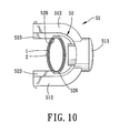
- the actuator 51 is movable in the mounting seat 42 radially relative to the tube axis (A) between a locking position (see Figures 4 to 7), where the positioning tube 1 is retained at the desired extended length relative to the support tube 2, and an unlocking position (see Figures 8 to 10), where the protruding members 523 cease to extend into the through holes 21 and the positioning holes 11 of the positioning hole units to permit adjustment of the extended length of the positioning tube 1 relative to the support tube 2.
- the stop portions 514 abut against front slot-defining walls 424 of the guide slots 422, as best shown in Figure 4.
- the stop portions 514 are spaced apart from the front slot-defining walls 424 of the guide slots 422, as best shown in Figure 8.
- the spring member 53 is disposed in the mounting seat 42, and has opposite ends abutting against the tubular sleeve 41 and the engaging member 52, respectively.
- the spring member 53 applies a biasing force to the actuator 51, and biases the actuator 51 to the locking position away from the positioning and support tubes 1, 2.
- each of the positioning holes 11 in the positioning tube 1 has a hole-defining wall with flat top and bottom edges 111, 112.
- Each of the through holes 21 in the support tube 2 has a hole-defining wall with flat top and bottom edges 211, 212.
- Each of the protruding members 523 of the engaging member 52 has flat top and bottom contact sides 524, 525.
- the actuator 51 When the positioning tube 1 is subjected to a load (V) while locked relative to the support tube 2, i.e., the actuator 51 is at the locking position, the top contact sides 524 of the protruding members 523 abut against the top edges 111 of the positioning holes 11, and the bottom contact sides 525 of the protruding members 523 abut against the bottom edges 212 of the through holes 21.
- the load (V) on the positioning tube 1 is shared by the protruding members 523 and is distributed evenly to the lateral sides of the support tube 2.
- the press part 511 of the actuator 51 is pushed in a direction (VI) shown in Figure 8 to move the actuator 51 in a radial inward direction relative to the tube axis (A) to the unlocking position, where the protruding members 523 cease to extend into the through holes 21 and the positioning holes 11 of the positioning hole units.
- curved edges 526 located at one end of the protruding members 523 opposite to the distal ends of the end arms 521 are moved to a rear side of the support tube 2.
- the extended length of the positioning tube 1 relative to the support tube 2 can be adjusted at this time so as to achieve a desired inclination for the seat member of the child vehicle safety seat.
- the press part 511 of the actuator 51 is released, and the spring member 53 biases the actuator 51 in the radial outward direction relative to the tube axis (A) to restore the actuator 51 to the locking position, thereby retaining the positioning tube 1 at the desired extended length relative to the support tube 2.
- the positioning tube 1 has a first tube portion to be connected to the seat member of the child vehicle safety seat, and a second tube portion opposite to the first tube portion.
- the second tube portion of the positioning tube 1 is formed with a first limit hole 12 proximate to a bottom end of the positioning tube 1
- the support tube 2 is formed with a second limit hole 22 proximate to an upper end of the support tube 2
- the tubular sleeve 41 is formed with a third limit hole 412 proximate to an upper end of the tubular sleeve 41.
- the first, second and third limit holes 12, 22, 412 are disposed at a rear side of the support device 100 and are similar in dimensions.
- the positioning tube 1 is further provided with a resilient limit component 13 therein to prevent removal of the positioning tube 1 from the support tube 2.
- the resilient limit component 13 is made of plastic, is formed in a U shape, and has a first end portion abutting against an inner tube surface of the positioning tube 1, and a second end portion formed with a hook 131.
- the protruding members 523 of the actuator 51 engage opposite lateral sides of the positioning and support tubes 1, 2 when the actuator 51 is at the locking position so that load forces on the positioning tube 1 can be distributed evenly to the lateral sides of the support tube 2, thus resulting in a sturdy construction for the support device 100 of this invention.
- movement of the actuator 51 results in corresponding movement of the protruding members 523, and due to the spring member 53 that biases the actuator 51 to the locking position, locking and unlocking of the positioning tube 1 relative to the support tube 2 can be accomplished with relative ease.
Landscapes
- Engineering & Computer Science (AREA)
- Mechanical Engineering (AREA)
- General Engineering & Computer Science (AREA)
- Health & Medical Sciences (AREA)
- Child & Adolescent Psychology (AREA)
- General Health & Medical Sciences (AREA)
- Aviation & Aerospace Engineering (AREA)
- Transportation (AREA)
- Seats For Vehicles (AREA)
- Chair Legs, Seat Parts, And Backrests (AREA)
Abstract
Description
- The invention relates to a support device, more particularly to a support device for a child vehicle safety seat.
- A child vehicle safety seat usually includes a support device connected to a front bottom part of a seat member for standing on a vehicle floor. The support device has a telescopic configuration so that the seat member can be placed stably on a vehicle seat at a desired inclination. One example of the conventional support device is disclosed in
Japanese patent publication number JP2003094994 - The conventional support device disclosed in the aforementioned Japanese patent publication is disadvantageous in that, since only one lateral side of a support member of the support device is formed with a plurality of spaced apart axially aligned positioning holes for engagement with a height adjusting mechanism, sturdiness of the support device is not satisfactory.
- Therefore, the object of the present invention is to provide a sturdy and easy-to-operate support device for a child vehicle safety seat.
- According to this invention, a support device is adapted for a child vehicle safety seat, and includes a positioning tube, a support tube, a support base, and a seat height adjusting unit.
- The positioning tube has a first tube portion adapted to be connected to the child vehicle safety seat, and a second tube portion opposite to the first tube portion. The positioning tube is formed with a plurality of positioning hole units spaced apart from each other along a tube axis. Each of the positioning hole units includes a pair of positioning holes that are disposed at diametrically opposite positions relative to the tube axis.
- The support tube is sleeved telescopically on the second tube portion of the positioning tube, and is formed with a pair of through holes that are disposed at diametrically opposite positions relative to the tube axis.
- The support base is sleeved on the support tube, and has a mounting seat disposed at a horizontal level corresponding to the through holes in the support tube.
- The seat height adjusting unit includes an actuator and a spring member. The actuator is mounted movably in the mounting seat, and has a pair of extending arms respectively disposed at opposite lateral sides of the support tube, and a pair of protruding members each disposed at a respective one of the extending arms. The protruding members are extendible into the through holes and the positioning holes of a registered one of the positioning hole units to retain the positioning tube at a desired extended length relative to the support tube. The spring member is disposed in the mounting seat and applies a biasing force to the actuator.
- Other features and advantages of the present invention will become apparent in the following detailed description of the preferred embodiment with reference to the accompanying drawings, of which:
- Figure 1 is an assembled perspective view of the preferred embodiment of a support device according to the present invention;
- Figure 2 is an exploded perspective view of the preferred embodiment;
- Figure 3 is an assembled perspective view of an actuator of the preferred embodiment;
- Figure 4 is a sectional view of the preferred embodiment, taken along line I-I in Figure 1, illustrating how a positioning tube is locked relative to a support tube;
- Figure 5 is a sectional view of the preferred embodiment, taken along line II-II in Figure 1, illustrating the positioning tube when locked relative to the support tube;
- Figure 6 is a fragmentary assembled perspective view of the preferred embodiment, illustrating the positioning tube when locked relative to the support tube;
- Figure 7 is a partly sectional schematic top view of the preferred embodiment, illustrating the positioning tube when locked relative to the support tube;
- Figure 8 is a view similar to Figure 4, but illustrating the positioning tube when unlocked relative to the support tube;
- Figure 9 is a fragmentary assembled perspective view of the preferred embodiment, illustrating the positioning tube when unlocked relative to the support tube;
- Figure 10 is a view similar to Figure 7, but illustrating the positioning tube when unlocked relative to the support tube; and
- Figure 11 is a fragmentary schematic sectional view of the preferred embodiment, taken along line III-III in Figure 1, illustrating a resilient limiting component that prevents removal of the positioning tube from the support tube.
- Figures 1 and 2 illustrate the preferred embodiment of a
support device 100 according to the present invention, which is adapted for connection to a front bottom part of a seat member of a child vehicle safety seat (not shown). Thesupport device 100 comprises apositioning tube 1 made of metal, asupport tube 2 made of metal and sleeved telescopically on thepositioning tube 1, anelongate floor base 3 fixed to a bottom end of thesupport tube 2 and to be disposed on a vehicle floor (not shown) , asupport base 4 made of plastic and sleeved on thesupport tube 2, and a seatheight adjusting unit 5 mounted in thesupport base 4 for retaining thepositioning tube 1 at a desired extended length relative to thesupport tube 2. - The
positioning tube 1 has a first tube portion to be connected to the seat member of the child vehicle safety seat, and a second tube portion opposite to the first tube portion. Thepositioning tube 1 has a tube wall formed with a plurality of positioning hole units which are spaced apart from each other along the direction of a tube axis (A). Each of the positioning hole units includes a pair of positioning holes 11 (see Figure 5) that are disposed at diametrically opposite positions relative to the tube axis (A). Since the feature of this invention does not reside in the connection between thepositioning tube 1 and the seat member of the child vehicle safety seat, a description of the same is omitted herein for the sake of brevity. - The
support tube 2 is sleeved telescopically on the second tube portion of thepositioning tube 1, and is formed with a pair of through holes 21 (see Figure 5) that are disposed at diametrically opposite positions relative to the tube axis (A). - The
support base 4 includes atubular sleeve 41 sleeved on thesupport tube 2, abase cap 43 formed integrally with a bottom end of thetubular sleeve 41 for covering thefloor base 3, and amounting seat 42 formed integrally on an upper part of thetubular sleeve 41. Themounting seat 42 extends transverse to the tube axis (A), and is disposed at a horizontal level corresponding to the throughholes 21 in thesupport tube 2. Themounting seat 42 has front and rearopen end portions front end portion 420 extends radially relative to the tube axis (A). Arear cap 423 is provided to close therear end portion 421 of themounting seat 42. - Referring to Figures 2, 3 and 4, the seat
height adjusting unit 5 is received in themounting seat 42 through thefront end portion 420, and includes anactuator 51 and aspring member 53. Theactuator 51 is mounted movably in themounting seat 42, and has a pair of extendingarms 512 that are respectively disposed at opposite lateral sides of thesupport tube 2, and acylindrical press part 511 that interconnects the extendingarms 512 and that is accessible from thefront end portion 420 of themounting seat 42. Each of the extendingarms 512 is formed with aresilient part 513, which is a cantilever structure. Eachresilient part 513 is connected to the respective extendingarm 512, and has a distal end formed with astop portion 514 that is disposed at an outer side of the respective extendingarm 512. In this embodiment, themounting seat 42 is formed with a guide slot unit that includes a pair oflateral guide slots 422, each of which is disposed adjacent to a respective one of the extendingarms 512 of theactuator 51. Thestop portions 514 extend movably and respectively into theguide slots 422 to limit range of movement of theactuator 51 relative to themounting seat 42. - The inner sides of the extending
arms 512 cooperate with a rear side of thepress part 511 to form aretaining groove 515. Theactuator 51 further includes a U-shapedengaging member 52 made of metal and retained in theretaining groove 515. Theengaging member 52 includes a pair ofresilient end arms 521 mounted respectively on the inner sides of the extendingarms 512, a pair ofbarb parts 522 each formed on an outer side of a distal end of a respective one of theend arms 521, and a pair of protrudingmembers 523 each formed on an inner side of the distal end of a respective one of theend arms 521. Eachbarb part 522 abuts against the inner side of the respective extendingarm 512 to retain firmly theengaging member 52 in theretaining groove 515. - The
tubular sleeve 41 is further formed with a pair of openings 411 (see Figure 5) registered with the throughholes 21 in thesupport tube 2. The protrudingmembers 523 are extendible into theopenings 411, the throughholes 21 and thepositioning holes 11 of a registered one of the positioning hole units in thepositioning tube 1 to retain thepositioning tube 1 at the desired extended length relative to thesupport tube 2. - The
actuator 51 is movable in themounting seat 42 radially relative to the tube axis (A) between a locking position (see Figures 4 to 7), where thepositioning tube 1 is retained at the desired extended length relative to thesupport tube 2, and an unlocking position (see Figures 8 to 10), where the protrudingmembers 523 cease to extend into the throughholes 21 and thepositioning holes 11 of the positioning hole units to permit adjustment of the extended length of thepositioning tube 1 relative to thesupport tube 2. When theactuator 51 is at the locking position, thestop portions 514 abut against front slot-definingwalls 424 of theguide slots 422, as best shown in Figure 4. On the other hand, when theactuator 51 is at the unlocking position, thestop portions 514 are spaced apart from the front slot-definingwalls 424 of theguide slots 422, as best shown in Figure 8. - The
spring member 53 is disposed in themounting seat 42, and has opposite ends abutting against thetubular sleeve 41 and theengaging member 52, respectively. Thespring member 53 applies a biasing force to theactuator 51, and biases theactuator 51 to the locking position away from the positioning andsupport tubes - As best shown in Figure 5, in this embodiment, each of the
positioning holes 11 in thepositioning tube 1 has a hole-defining wall with flat top andbottom edges holes 21 in thesupport tube 2 has a hole-defining wall with flat top andbottom edges members 523 of theengaging member 52 has flat top andbottom contact sides positioning tube 1 is subjected to a load (V) while locked relative to thesupport tube 2, i.e., theactuator 51 is at the locking position, thetop contact sides 524 of the protrudingmembers 523 abut against thetop edges 111 of thepositioning holes 11, and thebottom contact sides 525 of the protrudingmembers 523 abut against thebottom edges 212 of the throughholes 21. As a result, the load (V) on thepositioning tube 1 is shared by the protrudingmembers 523 and is distributed evenly to the lateral sides of thesupport tube 2. - Referring to Figures 8, 9 and 10, to adjust the extended length of the
positioning tube 1 relative to thesupport tube 2, thepress part 511 of theactuator 51 is pushed in a direction (VI) shown in Figure 8 to move theactuator 51 in a radial inward direction relative to the tube axis (A) to the unlocking position, where the protrudingmembers 523 cease to extend into the throughholes 21 and thepositioning holes 11 of the positioning hole units. At this time,curved edges 526 located at one end of the protrudingmembers 523 opposite to the distal ends of theend arms 521 are moved to a rear side of thesupport tube 2. The extended length of thepositioning tube 1 relative to thesupport tube 2 can be adjusted at this time so as to achieve a desired inclination for the seat member of the child vehicle safety seat. - After adjustment of the
positioning tube 1 to the desired extended length relative to thesupport tube 2, thepress part 511 of theactuator 51 is released, and thespring member 53 biases theactuator 51 in the radial outward direction relative to the tube axis (A) to restore theactuator 51 to the locking position, thereby retaining thepositioning tube 1 at the desired extended length relative to thesupport tube 2. - As previously described, the
positioning tube 1 has a first tube portion to be connected to the seat member of the child vehicle safety seat, and a second tube portion opposite to the first tube portion. As shown in Figures 2, 9 and 11, the second tube portion of thepositioning tube 1 is formed with afirst limit hole 12 proximate to a bottom end of thepositioning tube 1, thesupport tube 2 is formed with asecond limit hole 22 proximate to an upper end of thesupport tube 2, and thetubular sleeve 41 is formed with athird limit hole 412 proximate to an upper end of thetubular sleeve 41. The first, second and third limit holes 12, 22, 412 are disposed at a rear side of thesupport device 100 and are similar in dimensions. Thepositioning tube 1 is further provided with aresilient limit component 13 therein to prevent removal of thepositioning tube 1 from thesupport tube 2. In this embodiment, theresilient limit component 13 is made of plastic, is formed in a U shape, and has a first end portion abutting against an inner tube surface of thepositioning tube 1, and a second end portion formed with ahook 131. When the limit holes 12, 22, 412 are aligned during adjustment of the extended length of thepositioning tube 1 relative to thesupport tube 2, thehook 131 extends into the limit holes 12, 22, 412, and a flattop contact side 133 of thehook 131 abuts against flat top hole edges of the limit holes 12, 22, 412, thereby preventing further movement of thepositioning tube 1 relative to thesupport tube 2 in a direction away from thefloor base 3. - In sum, the protruding
members 523 of theactuator 51 engage opposite lateral sides of the positioning andsupport tubes actuator 51 is at the locking position so that load forces on thepositioning tube 1 can be distributed evenly to the lateral sides of thesupport tube 2, thus resulting in a sturdy construction for thesupport device 100 of this invention. In addition, since movement of theactuator 51 results in corresponding movement of the protrudingmembers 523, and due to thespring member 53 that biases theactuator 51 to the locking position, locking and unlocking of thepositioning tube 1 relative to thesupport tube 2 can be accomplished with relative ease.
Claims (14)
- A support device (100) for a child vehicle safety seat, characterized by:a positioning tube (1) having a first tube portion adapted to be connected to the child vehicle safety seat, and a second tube portion opposite to said first tube portion, said positioning tube (1) being formed with a plurality of positioning hole units spaced apart from each other along a tube axis (A), each of said positioning hole units including a pair of positioning holes (11) that are disposed at diametrically opposite positions relative to the tube axis (A);a support tube (2) sleeved telescopically on said second tube portion of said positioning tube (1) and formed with apair of through holes (21) that are disposed at diametrically opposite positions relative to the tube axis (A);a support base (4) sleeved on said support tube (2), and having a mounting seat (42) disposed at a horizontal level corresponding to said through holes (21) in said support tube (2); anda seat height adjusting unit (5) including an actuator (51) mounted movably in said mounting seat (42) and having a pair of extending arms (512) respectively disposed at opposite lateral sides of said support tube (2), and a pair of protruding members (523) each disposed at a respective one of said extending arms (512), said protruding members (523) being extendible into said through holes (21) and said positioning holes (11) of a registered one of said positioning hole units to retain said positioning tube (1) at a desired extended length relative to said support tube (2), anda spring member (53) disposed in said mounting seat (42) for applying a biasing force to said actuator (51).
- The support device (100) as claimed in Claim 1, characterized in that said actuator (51) is movable in saidmounting seat (42) between a locking position, where said positioning tube (1) is retained at the desired extended length relative to said support tube (2), and an unlocking position, where said protruding members (523) cease to extend into said through holes (21) and said positioning holes (11) of said positioning hole units to permit adjustment of the extended length of said positioning tube (1) relative to said support tube (2).
- The support device (100) as claimed in Claim 2, further characterized in that said actuator (51) is movable in a radial direction relative to the tube axis (A), and said spring member (53) biases said actuator (51) to the locking position away from said positioning and support tubes (1, 2).
- The support device (100) as claimed in Claim 1, characterized in that said mounting seat (42) is formed with a guide slot unit that includes a pair of lateral guide slots (422), eachdisposedadjacent to a respective one of said extending arms (512) of said actuator (51),
said actuator (51) further having a pair of stop portions (514) each disposed at an outer side of a respective one of said extending arms (512), said stop portions (514) extending movably and respectively into said guide slots (422) to limit range of movement of said actuator (51) relative to said mounting seat (42). - The support device (100) as claimed in Claim 1, characterized in that said mounting seat (42) has an open end portion (420) that extends radially relative to the tube axis (A), said actuator (51) including a press part (511) that interconnects said extending arms (512) and that is accessible from said open end portion (420) of said mounting seat (42).
- The support device (100) as claimed in Claim 1, characterized in that each of said positioning holes (11) has a hole-defining wall with a flat top edge (111), and each of said through holes (21) has a hole-defining wall with a flat bottom edge (212),
said protruding members (523) abutting against said top edges (111) of said positioning holes (11) of the registered one of said positioning holes units and further against said bottom edges (212) of said through holes (21) to retain said positioning tube (1) at the desired extended length relative to said support tube (2). - The support device (100) as claimed in Claim 1, characterized in that said actuator (51) includes a U-shaped engaging member (52), said engaging member (52) having a pair of end arms (521) mounted respectively on inner sides of said extending arms (512), each of said protruding members (523) being formed on a distal end of a respective one of said end arms (521).
- The support device (100) as claimed in Claim 7, further characterized in that each of said end arms (521) of said engaging member (52) has a barb part (522) that abuts against the respective one of said extending arms (512) to retain said engaging member (52) on said extending arms (512).
- The support device (100) as claimed in Claim 1, characterized in that said positioning tube (1) is provided with a resilient limit component (13) therein to prevent removal of said positioning tube (1) from said support tube (2).
- The support device (100) as claimed in Claim 9, further characterized in that said second tube portion of said positioning tube (1) is formed with a first limit hole (12), said support tube (2) being formed with a second limit hole (22) proximate to an upper end of said support tube (2), said resilient limit component (13) being formed in a U shape and having an end portion formed with a hook (131), said hook (131) being extendible removably into said first and second limit holes (12, 22) to prevent removal of said positioning tube (1) from said support tube (2).
- The support device (100) as claimed in Claim 10, characterized in that said support base (4) further has a tubular sleeve (41) sleeved on said support tube (2), said mounting seat (42) being formed on said tubular sleeve (41), said tubular sleeve (41) being formed with a third limit hole (412) proximate to an upper end of said tubular sleeve (41), said hook (131) being extendible removably into said first, second and third limit holes (12, 22, 412).
- A support device (100) characterized by:a positioning tube (1) formed with a plurality of positioning hole units spaced apart from each other along a tube axis (A), each of said positioning hole units including a pair of positioning holes (11) that are disposed at diametrically opposite positions relative to the tube axis (A);a support member sleeved telescopically on said positioning tube (1) and formed with a pair of through holes (21) that are disposed at diametrically opposite positions relative to the tube axis (A), said support member having a mounting seat (42) disposed at a horizontal level corresponding to said through holes (21); andan actuator (51) mounted movably in said mounting seat (42) and having two protruding portions (523) that correspond respectively in position to said through holes (21), said actuator (51) being biased for movement between a locking position, where said protruding portions (523) engage said through holes (21) and said positioning holes (11) of a registered one of said positioning hole units to retain said positioning tube (1) at a desired extended length relative to said support member, and an unlocking position, where said protruding portions (523) are disengaged from said through holes (21) and said positioning holes (11) of said positioning hole units to permit adjustment of the extended length of said positioning tube (1) relative to said support member.
- The support device (100) as claimed in Claim 12, characterized in that said actuator (51) is movable in a radial direction relative to the tube axis (A).
- The support device (100) as claimed in Claim 12, characterized in that said actuator (51) is U-shaped and has a pair of end arms (521), each of said protruding portions (523) being disposed at a respective one of said end arms (521).
Applications Claiming Priority (1)
| Application Number | Priority Date | Filing Date | Title |
|---|---|---|---|
| CNU2006201241326U CN2928580Y (en) | 2006-08-02 | 2006-08-02 | Child car seat supports |
Publications (3)
| Publication Number | Publication Date |
|---|---|
| EP1884400A2 true EP1884400A2 (en) | 2008-02-06 |
| EP1884400A3 EP1884400A3 (en) | 2009-05-20 |
| EP1884400B1 EP1884400B1 (en) | 2011-01-26 |
Family
ID=38306968
Family Applications (1)
| Application Number | Title | Priority Date | Filing Date |
|---|---|---|---|
| EP07252041A Active EP1884400B1 (en) | 2006-08-02 | 2007-05-18 | Support device for a child vehicle safety seat |
Country Status (5)
| Country | Link |
|---|---|
| US (1) | US7441733B2 (en) |
| EP (1) | EP1884400B1 (en) |
| CN (1) | CN2928580Y (en) |
| AT (1) | ATE496796T1 (en) |
| DE (1) | DE602007012178D1 (en) |
Cited By (2)
| Publication number | Priority date | Publication date | Assignee | Title |
|---|---|---|---|---|
| GB2489822A (en) * | 2011-04-07 | 2012-10-10 | Wonderland Nursery Goods | Support device for child safety seat |
| GB2492201A (en) * | 2011-06-21 | 2012-12-26 | Bp Childrens Prod Hk Co Ltd | Safety seat device including support leg unit |
Families Citing this family (27)
| Publication number | Priority date | Publication date | Assignee | Title |
|---|---|---|---|---|
| ES2343770B1 (en) * | 2007-12-20 | 2011-06-24 | Universitat Politècnica De Catalunya | CONTINUOUS HEIGHT REGULATION DEVICE OF A SUPPORT BAR THROUGH THREADING FOR A CHILD RETENTION SYSTEM INTENDED FOR THE TRANSPORTATION OF CHILDREN IN A MOTOR VEHICLE. |
| ES2343769B1 (en) * | 2007-12-20 | 2011-06-24 | Universitat Politècnica De Catalunya | CONTINUOUS HEIGHT ADJUSTMENT SUPPORT BAR DEVICE FOR A CHILD RETENTION SYSTEM FOR THE TRANSPORTATION OF CHILDREN IN A MOTOR VEHICLE. |
| CN103182966B (en) * | 2008-07-02 | 2015-11-18 | 康贝株式会社 | Child seat |
| CN101976585B (en) * | 2010-11-01 | 2013-04-17 | 江苏永发医用设备有限公司 | Manual mechanical height adjusting device |
| CN102582479B (en) * | 2011-01-06 | 2014-11-05 | 明门香港股份有限公司 | Supporting device |
| US8596598B2 (en) * | 2011-01-31 | 2013-12-03 | Yu-Shan Lai | Table with telescopic legs |
| EP2546096B1 (en) * | 2011-07-14 | 2013-09-11 | Volvo Car Corporation | Child seat |
| CN103156433B (en) | 2011-12-15 | 2015-09-02 | 宝钜(中国)儿童用品有限公司 | Baby bedstead |
| CN103802695A (en) * | 2014-01-21 | 2014-05-21 | 宁波环球娃娃婴童用品有限公司 | Supporting leg assembly of child safety seat |
| CN103950398A (en) * | 2014-04-18 | 2014-07-30 | 好孩子儿童用品有限公司 | Supporting leg of automobile seat for children |
| US9400080B2 (en) * | 2014-04-28 | 2016-07-26 | Victor Hung | Automatic rise jack stand |
| CN105799559B (en) * | 2014-12-31 | 2018-04-13 | 明门香港股份有限公司 | Height adjusting mechanism and infant carrier with same |
| US20170128658A1 (en) * | 2015-11-11 | 2017-05-11 | CreatiVasc Medical Inc. | Arteriovenous access valve system with separate valve tubes |
| CN107826001B (en) * | 2016-09-16 | 2020-05-22 | 明门瑞士股份有限公司 | Supporting leg and child safety seat assembly thereof |
| CN106740313B (en) * | 2017-01-09 | 2020-05-26 | 苏州纪宝儿童用品有限公司 | Supporting leg structure of child safety seat |
| US10315539B2 (en) | 2017-05-09 | 2019-06-11 | Dorel Juvenile Group, Inc. | Child restraint with vehicle seatbelt management system |
| ES2806278T3 (en) * | 2017-09-14 | 2021-02-17 | Britax Roemer Kindersicherheit Gmbh | Support leg for a child safety seat |
| CN109974956B (en) * | 2017-12-28 | 2024-03-22 | 明门(中国)幼童用品有限公司 | Column support piece strength testing device |
| US11097639B2 (en) * | 2018-05-24 | 2021-08-24 | Wonderland Switzerland Ag | Support base for a child safety seat |
| CN112519646B (en) | 2019-09-17 | 2023-05-30 | 明门瑞士股份有限公司 | Infant safety seat and seat base |
| US11691543B2 (en) | 2020-04-14 | 2023-07-04 | Wonderland Switzerland Ag | Infant car seat and stability leg and release actuator |
| USD1074287S1 (en) | 2020-09-17 | 2025-05-13 | Wonderland Switzerland Ag | Base for infant car seat |
| CN113069286A (en) * | 2021-05-08 | 2021-07-06 | 安维车件(厦门)有限公司 | Level adjusting device and headrest thereof |
| CN115675204A (en) * | 2021-07-21 | 2023-02-03 | 明门瑞士股份有限公司 | Infant carrier with improved sliding mechanism |
| DE102022120780A1 (en) * | 2022-08-17 | 2024-02-22 | Peri Se | Lowering device, support device and ceiling formwork, as well as methods for lowering and raising a building support |
| GB2627915A (en) * | 2023-02-22 | 2024-09-11 | Jcco 330 Ltd | Improvements in and relating to cable/pipe supports |
| US20260022725A1 (en) * | 2024-07-22 | 2026-01-22 | Step2Gold Co., Ltd. | Telescopic tube device |
Citations (1)
| Publication number | Priority date | Publication date | Assignee | Title |
|---|---|---|---|---|
| JP2003094994A (en) | 2001-09-25 | 2003-04-03 | Combi Corp | Support leg device for child seat |
Family Cites Families (6)
| Publication number | Priority date | Publication date | Assignee | Title |
|---|---|---|---|---|
| US4577837A (en) * | 1984-07-30 | 1986-03-25 | Marvin Berg | Locking mechanism for extendible telescoping tubular members |
| US5370500A (en) * | 1994-03-14 | 1994-12-06 | Thompson; Jerry E. | Oscillating fan support |
| DE10034592C1 (en) * | 2000-07-14 | 2002-04-18 | Steinco Paul Vom Stein Gmbh | Height adjustment for telescopic tubes, for walking aids or invalid carriages and wheelchairs, has a spring clip at the outer tube with end cheeks to carry locking studs through the outer tube into the inner tube |
| CA2314476C (en) * | 2000-07-20 | 2007-03-20 | Gordon Lamont | Anti-fatigue platform |
| US20030042373A1 (en) * | 2001-09-06 | 2003-03-06 | Macleod Edward | Ergonomic positioning apparatus for computers and or computer accessories |
| KR101253569B1 (en) * | 2006-05-09 | 2013-04-11 | 삼성전자주식회사 | Supporting device for display device |
-
2006
- 2006-08-02 CN CNU2006201241326U patent/CN2928580Y/en not_active Expired - Lifetime
-
2007
- 2007-05-18 DE DE602007012178T patent/DE602007012178D1/en active Active
- 2007-05-18 EP EP07252041A patent/EP1884400B1/en active Active
- 2007-05-18 AT AT07252041T patent/ATE496796T1/en not_active IP Right Cessation
- 2007-06-04 US US11/806,760 patent/US7441733B2/en active Active
Patent Citations (1)
| Publication number | Priority date | Publication date | Assignee | Title |
|---|---|---|---|---|
| JP2003094994A (en) | 2001-09-25 | 2003-04-03 | Combi Corp | Support leg device for child seat |
Cited By (4)
| Publication number | Priority date | Publication date | Assignee | Title |
|---|---|---|---|---|
| GB2489822A (en) * | 2011-04-07 | 2012-10-10 | Wonderland Nursery Goods | Support device for child safety seat |
| GB2489822B (en) * | 2011-04-07 | 2017-07-26 | Wonderland Nursery Goods | Support device for child safety seat |
| GB2492201A (en) * | 2011-06-21 | 2012-12-26 | Bp Childrens Prod Hk Co Ltd | Safety seat device including support leg unit |
| GB2492201B (en) * | 2011-06-21 | 2018-06-13 | Bp Childrens Products Hk Co Ltd | Safety seat device |
Also Published As
| Publication number | Publication date |
|---|---|
| US20080030052A1 (en) | 2008-02-07 |
| EP1884400B1 (en) | 2011-01-26 |
| ATE496796T1 (en) | 2011-02-15 |
| EP1884400A3 (en) | 2009-05-20 |
| CN2928580Y (en) | 2007-08-01 |
| DE602007012178D1 (en) | 2011-03-10 |
| US7441733B2 (en) | 2008-10-28 |
Similar Documents
| Publication | Publication Date | Title |
|---|---|---|
| EP1884400B1 (en) | Support device for a child vehicle safety seat | |
| US8047096B2 (en) | Lock mechanism for an adjustable steering column assembly | |
| EP2332807B1 (en) | Stroller connectable with a car seat | |
| US6220389B1 (en) | Folding ladder | |
| EP1122486B1 (en) | Tripod | |
| US6997611B2 (en) | Positioning device for a multi-section slide track assembly of drawers | |
| US9199556B2 (en) | Hinge assembly for vehicle seat and vehicle seat comprising such a hinge assembly | |
| EP2450156A1 (en) | Collapsible saw horses | |
| EP2478148B1 (en) | Ironing board | |
| WO2015035211A2 (en) | Adjustable ladders, ladder components and related methods | |
| US7753448B2 (en) | Seat position-adjusting device for a highchair | |
| US20060051159A1 (en) | Positioning device for a foldable structure | |
| US20040075327A1 (en) | Footrest apparatus for a wheel chair and method of adjusting the same | |
| GB2433027A (en) | Telescopic support leg | |
| EP3222495B1 (en) | Steering column device | |
| CN221769673U (en) | Children's Carrier | |
| JP4651449B2 (en) | Elevating guide device such as top plate | |
| US20080106053A1 (en) | Handle positioning device for a hand truck | |
| CN117916476A (en) | Folding length adjustment mechanism | |
| JP4925175B2 (en) | Ottoman for vehicle seat | |
| JP3007296B2 (en) | Furniture top plate lifting device | |
| US20040084944A1 (en) | Height adjustment mechanism for an infant support structure | |
| EP1101989B1 (en) | Rail attachment system with locking member | |
| JP2006207798A (en) | Telescopic device | |
| US11292383B2 (en) | Truck bed utility bar |
Legal Events
| Date | Code | Title | Description |
|---|---|---|---|
| PUAI | Public reference made under article 153(3) epc to a published international application that has entered the european phase |
Free format text: ORIGINAL CODE: 0009012 |
|
| AK | Designated contracting states |
Kind code of ref document: A2 Designated state(s): AT BE BG CH CY CZ DE DK EE ES FI FR GB GR HU IE IS IT LI LT LU LV MC MT NL PL PT RO SE SI SK TR |
|
| AX | Request for extension of the european patent |
Extension state: AL BA HR MK YU |
|
| PUAL | Search report despatched |
Free format text: ORIGINAL CODE: 0009013 |
|
| AK | Designated contracting states |
Kind code of ref document: A3 Designated state(s): AT BE BG CH CY CZ DE DK EE ES FI FR GB GR HU IE IS IT LI LT LU LV MC MT NL PL PT RO SE SI SK TR |
|
| AX | Request for extension of the european patent |
Extension state: AL BA HR MK RS |
|
| 17P | Request for examination filed |
Effective date: 20091118 |
|
| AKX | Designation fees paid |
Designated state(s): AT BE BG CH CY CZ DE DK EE ES FI FR GB GR HU IE IS IT LI LT LU LV MC MT NL PL PT RO SE SI SK TR |
|
| GRAP | Despatch of communication of intention to grant a patent |
Free format text: ORIGINAL CODE: EPIDOSNIGR1 |
|
| GRAC | Information related to communication of intention to grant a patent modified |
Free format text: ORIGINAL CODE: EPIDOSCIGR1 |
|
| GRAJ | Information related to disapproval of communication of intention to grant by the applicant or resumption of examination proceedings by the epo deleted |
Free format text: ORIGINAL CODE: EPIDOSDIGR1 |
|
| GRAP | Despatch of communication of intention to grant a patent |
Free format text: ORIGINAL CODE: EPIDOSNIGR1 |
|
| GRAC | Information related to communication of intention to grant a patent modified |
Free format text: ORIGINAL CODE: EPIDOSCIGR1 |
|
| GRAS | Grant fee paid |
Free format text: ORIGINAL CODE: EPIDOSNIGR3 |
|
| GRAA | (expected) grant |
Free format text: ORIGINAL CODE: 0009210 |
|
| AK | Designated contracting states |
Kind code of ref document: B1 Designated state(s): AT BE BG CH CY CZ DE DK EE ES FI FR GB GR HU IE IS IT LI LT LU LV MC MT NL PL PT RO SE SI SK TR |
|
| REG | Reference to a national code |
Ref country code: GB Ref legal event code: FG4D |
|
| REG | Reference to a national code |
Ref country code: CH Ref legal event code: EP |
|
| REG | Reference to a national code |
Ref country code: IE Ref legal event code: FG4D |
|
| REF | Corresponds to: |
Ref document number: 602007012178 Country of ref document: DE Date of ref document: 20110310 Kind code of ref document: P |
|
| REG | Reference to a national code |
Ref country code: DE Ref legal event code: R096 Ref document number: 602007012178 Country of ref document: DE Effective date: 20110310 |
|
| REG | Reference to a national code |
Ref country code: NL Ref legal event code: VDEP Effective date: 20110126 |
|
| LTIE | Lt: invalidation of european patent or patent extension |
Effective date: 20110126 |
|
| PG25 | Lapsed in a contracting state [announced via postgrant information from national office to epo] |
Ref country code: PT Free format text: LAPSE BECAUSE OF FAILURE TO SUBMIT A TRANSLATION OF THE DESCRIPTION OR TO PAY THE FEE WITHIN THE PRESCRIBED TIME-LIMIT Effective date: 20110526 Ref country code: SE Free format text: LAPSE BECAUSE OF FAILURE TO SUBMIT A TRANSLATION OF THE DESCRIPTION OR TO PAY THE FEE WITHIN THE PRESCRIBED TIME-LIMIT Effective date: 20110126 Ref country code: LT Free format text: LAPSE BECAUSE OF FAILURE TO SUBMIT A TRANSLATION OF THE DESCRIPTION OR TO PAY THE FEE WITHIN THE PRESCRIBED TIME-LIMIT Effective date: 20110126 Ref country code: GR Free format text: LAPSE BECAUSE OF FAILURE TO SUBMIT A TRANSLATION OF THE DESCRIPTION OR TO PAY THE FEE WITHIN THE PRESCRIBED TIME-LIMIT Effective date: 20110427 Ref country code: ES Free format text: LAPSE BECAUSE OF FAILURE TO SUBMIT A TRANSLATION OF THE DESCRIPTION OR TO PAY THE FEE WITHIN THE PRESCRIBED TIME-LIMIT Effective date: 20110507 Ref country code: IS Free format text: LAPSE BECAUSE OF FAILURE TO SUBMIT A TRANSLATION OF THE DESCRIPTION OR TO PAY THE FEE WITHIN THE PRESCRIBED TIME-LIMIT Effective date: 20110526 Ref country code: LV Free format text: LAPSE BECAUSE OF FAILURE TO SUBMIT A TRANSLATION OF THE DESCRIPTION OR TO PAY THE FEE WITHIN THE PRESCRIBED TIME-LIMIT Effective date: 20110126 |
|
| PG25 | Lapsed in a contracting state [announced via postgrant information from national office to epo] |
Ref country code: AT Free format text: LAPSE BECAUSE OF FAILURE TO SUBMIT A TRANSLATION OF THE DESCRIPTION OR TO PAY THE FEE WITHIN THE PRESCRIBED TIME-LIMIT Effective date: 20110126 Ref country code: PL Free format text: LAPSE BECAUSE OF FAILURE TO SUBMIT A TRANSLATION OF THE DESCRIPTION OR TO PAY THE FEE WITHIN THE PRESCRIBED TIME-LIMIT Effective date: 20110126 Ref country code: FI Free format text: LAPSE BECAUSE OF FAILURE TO SUBMIT A TRANSLATION OF THE DESCRIPTION OR TO PAY THE FEE WITHIN THE PRESCRIBED TIME-LIMIT Effective date: 20110126 Ref country code: SI Free format text: LAPSE BECAUSE OF FAILURE TO SUBMIT A TRANSLATION OF THE DESCRIPTION OR TO PAY THE FEE WITHIN THE PRESCRIBED TIME-LIMIT Effective date: 20110126 Ref country code: CY Free format text: LAPSE BECAUSE OF FAILURE TO SUBMIT A TRANSLATION OF THE DESCRIPTION OR TO PAY THE FEE WITHIN THE PRESCRIBED TIME-LIMIT Effective date: 20110126 Ref country code: BE Free format text: LAPSE BECAUSE OF FAILURE TO SUBMIT A TRANSLATION OF THE DESCRIPTION OR TO PAY THE FEE WITHIN THE PRESCRIBED TIME-LIMIT Effective date: 20110126 Ref country code: BG Free format text: LAPSE BECAUSE OF FAILURE TO SUBMIT A TRANSLATION OF THE DESCRIPTION OR TO PAY THE FEE WITHIN THE PRESCRIBED TIME-LIMIT Effective date: 20110426 Ref country code: NL Free format text: LAPSE BECAUSE OF FAILURE TO SUBMIT A TRANSLATION OF THE DESCRIPTION OR TO PAY THE FEE WITHIN THE PRESCRIBED TIME-LIMIT Effective date: 20110126 |
|
| PG25 | Lapsed in a contracting state [announced via postgrant information from national office to epo] |
Ref country code: DK Free format text: LAPSE BECAUSE OF FAILURE TO SUBMIT A TRANSLATION OF THE DESCRIPTION OR TO PAY THE FEE WITHIN THE PRESCRIBED TIME-LIMIT Effective date: 20110126 Ref country code: EE Free format text: LAPSE BECAUSE OF FAILURE TO SUBMIT A TRANSLATION OF THE DESCRIPTION OR TO PAY THE FEE WITHIN THE PRESCRIBED TIME-LIMIT Effective date: 20110126 |
|
| PG25 | Lapsed in a contracting state [announced via postgrant information from national office to epo] |
Ref country code: CZ Free format text: LAPSE BECAUSE OF FAILURE TO SUBMIT A TRANSLATION OF THE DESCRIPTION OR TO PAY THE FEE WITHIN THE PRESCRIBED TIME-LIMIT Effective date: 20110126 Ref country code: RO Free format text: LAPSE BECAUSE OF FAILURE TO SUBMIT A TRANSLATION OF THE DESCRIPTION OR TO PAY THE FEE WITHIN THE PRESCRIBED TIME-LIMIT Effective date: 20110126 Ref country code: SK Free format text: LAPSE BECAUSE OF FAILURE TO SUBMIT A TRANSLATION OF THE DESCRIPTION OR TO PAY THE FEE WITHIN THE PRESCRIBED TIME-LIMIT Effective date: 20110126 |
|
| PLBE | No opposition filed within time limit |
Free format text: ORIGINAL CODE: 0009261 |
|
| STAA | Information on the status of an ep patent application or granted ep patent |
Free format text: STATUS: NO OPPOSITION FILED WITHIN TIME LIMIT |
|
| PG25 | Lapsed in a contracting state [announced via postgrant information from national office to epo] |
Ref country code: MC Free format text: LAPSE BECAUSE OF NON-PAYMENT OF DUE FEES Effective date: 20110531 Ref country code: MT Free format text: LAPSE BECAUSE OF FAILURE TO SUBMIT A TRANSLATION OF THE DESCRIPTION OR TO PAY THE FEE WITHIN THE PRESCRIBED TIME-LIMIT Effective date: 20110126 |
|
| REG | Reference to a national code |
Ref country code: CH Ref legal event code: PL |
|
| 26N | No opposition filed |
Effective date: 20111027 |
|
| PG25 | Lapsed in a contracting state [announced via postgrant information from national office to epo] |
Ref country code: CH Free format text: LAPSE BECAUSE OF NON-PAYMENT OF DUE FEES Effective date: 20110531 Ref country code: LI Free format text: LAPSE BECAUSE OF NON-PAYMENT OF DUE FEES Effective date: 20110531 |
|
| REG | Reference to a national code |
Ref country code: DE Ref legal event code: R097 Ref document number: 602007012178 Country of ref document: DE Effective date: 20111027 |
|
| REG | Reference to a national code |
Ref country code: IE Ref legal event code: MM4A |
|
| PG25 | Lapsed in a contracting state [announced via postgrant information from national office to epo] |
Ref country code: IE Free format text: LAPSE BECAUSE OF NON-PAYMENT OF DUE FEES Effective date: 20110518 |
|
| PG25 | Lapsed in a contracting state [announced via postgrant information from national office to epo] |
Ref country code: IT Free format text: LAPSE BECAUSE OF FAILURE TO SUBMIT A TRANSLATION OF THE DESCRIPTION OR TO PAY THE FEE WITHIN THE PRESCRIBED TIME-LIMIT Effective date: 20110126 |
|
| PG25 | Lapsed in a contracting state [announced via postgrant information from national office to epo] |
Ref country code: LU Free format text: LAPSE BECAUSE OF NON-PAYMENT OF DUE FEES Effective date: 20110518 |
|
| PG25 | Lapsed in a contracting state [announced via postgrant information from national office to epo] |
Ref country code: TR Free format text: LAPSE BECAUSE OF FAILURE TO SUBMIT A TRANSLATION OF THE DESCRIPTION OR TO PAY THE FEE WITHIN THE PRESCRIBED TIME-LIMIT Effective date: 20110126 |
|
| PG25 | Lapsed in a contracting state [announced via postgrant information from national office to epo] |
Ref country code: HU Free format text: LAPSE BECAUSE OF FAILURE TO SUBMIT A TRANSLATION OF THE DESCRIPTION OR TO PAY THE FEE WITHIN THE PRESCRIBED TIME-LIMIT Effective date: 20110126 |
|
| REG | Reference to a national code |
Ref country code: FR Ref legal event code: PLFP Year of fee payment: 10 |
|
| REG | Reference to a national code |
Ref country code: FR Ref legal event code: PLFP Year of fee payment: 11 |
|
| REG | Reference to a national code |
Ref country code: FR Ref legal event code: PLFP Year of fee payment: 12 |
|
| P01 | Opt-out of the competence of the unified patent court (upc) registered |
Effective date: 20230522 |
|
| PGFP | Annual fee paid to national office [announced via postgrant information from national office to epo] |
Ref country code: DE Payment date: 20250325 Year of fee payment: 19 |
|
| PGFP | Annual fee paid to national office [announced via postgrant information from national office to epo] |
Ref country code: GB Payment date: 20260312 Year of fee payment: 20 |
|
| PGFP | Annual fee paid to national office [announced via postgrant information from national office to epo] |
Ref country code: FR Payment date: 20260331 Year of fee payment: 20 |