EP1884218A1 - Sheath unit for recovering thrombus capture member and thrombus capture catheter unit - Google Patents
Sheath unit for recovering thrombus capture member and thrombus capture catheter unit Download PDFInfo
- Publication number
- EP1884218A1 EP1884218A1 EP07113491A EP07113491A EP1884218A1 EP 1884218 A1 EP1884218 A1 EP 1884218A1 EP 07113491 A EP07113491 A EP 07113491A EP 07113491 A EP07113491 A EP 07113491A EP 1884218 A1 EP1884218 A1 EP 1884218A1
- Authority
- EP
- European Patent Office
- Prior art keywords
- sheath
- thrombus capture
- capture member
- thrombus
- tip
- Prior art date
- Legal status (The legal status is an assumption and is not a legal conclusion. Google has not performed a legal analysis and makes no representation as to the accuracy of the status listed.)
- Granted
Links
Images



Classifications
-
- A—HUMAN NECESSITIES
- A61—MEDICAL OR VETERINARY SCIENCE; HYGIENE
- A61F—FILTERS IMPLANTABLE INTO BLOOD VESSELS; PROSTHESES; DEVICES PROVIDING PATENCY TO, OR PREVENTING COLLAPSING OF, TUBULAR STRUCTURES OF THE BODY, e.g. STENTS; ORTHOPAEDIC, NURSING OR CONTRACEPTIVE DEVICES; FOMENTATION; TREATMENT OR PROTECTION OF EYES OR EARS; BANDAGES, DRESSINGS OR ABSORBENT PADS; FIRST-AID KITS
- A61F2/00—Filters implantable into blood vessels; Prostheses, i.e. artificial substitutes or replacements for parts of the body; Appliances for connecting them with the body; Devices providing patency to, or preventing collapsing of, tubular structures of the body, e.g. stents
- A61F2/01—Filters implantable into blood vessels
- A61F2/011—Instruments for their placement or removal
-
- A—HUMAN NECESSITIES
- A61—MEDICAL OR VETERINARY SCIENCE; HYGIENE
- A61F—FILTERS IMPLANTABLE INTO BLOOD VESSELS; PROSTHESES; DEVICES PROVIDING PATENCY TO, OR PREVENTING COLLAPSING OF, TUBULAR STRUCTURES OF THE BODY, e.g. STENTS; ORTHOPAEDIC, NURSING OR CONTRACEPTIVE DEVICES; FOMENTATION; TREATMENT OR PROTECTION OF EYES OR EARS; BANDAGES, DRESSINGS OR ABSORBENT PADS; FIRST-AID KITS
- A61F2/00—Filters implantable into blood vessels; Prostheses, i.e. artificial substitutes or replacements for parts of the body; Appliances for connecting them with the body; Devices providing patency to, or preventing collapsing of, tubular structures of the body, e.g. stents
- A61F2/01—Filters implantable into blood vessels
- A61F2/013—Distal protection devices, i.e. devices placed distally in combination with another endovascular procedure, e.g. angioplasty or stenting
- A61F2002/015—Stop means therefor
-
- A—HUMAN NECESSITIES
- A61—MEDICAL OR VETERINARY SCIENCE; HYGIENE
- A61F—FILTERS IMPLANTABLE INTO BLOOD VESSELS; PROSTHESES; DEVICES PROVIDING PATENCY TO, OR PREVENTING COLLAPSING OF, TUBULAR STRUCTURES OF THE BODY, e.g. STENTS; ORTHOPAEDIC, NURSING OR CONTRACEPTIVE DEVICES; FOMENTATION; TREATMENT OR PROTECTION OF EYES OR EARS; BANDAGES, DRESSINGS OR ABSORBENT PADS; FIRST-AID KITS
- A61F2/00—Filters implantable into blood vessels; Prostheses, i.e. artificial substitutes or replacements for parts of the body; Appliances for connecting them with the body; Devices providing patency to, or preventing collapsing of, tubular structures of the body, e.g. stents
- A61F2/01—Filters implantable into blood vessels
- A61F2002/018—Filters implantable into blood vessels made from tubes or sheets of material, e.g. by etching or laser-cutting
-
- A—HUMAN NECESSITIES
- A61—MEDICAL OR VETERINARY SCIENCE; HYGIENE
- A61F—FILTERS IMPLANTABLE INTO BLOOD VESSELS; PROSTHESES; DEVICES PROVIDING PATENCY TO, OR PREVENTING COLLAPSING OF, TUBULAR STRUCTURES OF THE BODY, e.g. STENTS; ORTHOPAEDIC, NURSING OR CONTRACEPTIVE DEVICES; FOMENTATION; TREATMENT OR PROTECTION OF EYES OR EARS; BANDAGES, DRESSINGS OR ABSORBENT PADS; FIRST-AID KITS
- A61F2230/00—Geometry of prostheses classified in groups A61F2/00 - A61F2/26 or A61F2/82 or A61F9/00 or A61F11/00 or subgroups thereof
- A61F2230/0002—Two-dimensional shapes, e.g. cross-sections
- A61F2230/0004—Rounded shapes, e.g. with rounded corners
- A61F2230/0006—Rounded shapes, e.g. with rounded corners circular
-
- A—HUMAN NECESSITIES
- A61—MEDICAL OR VETERINARY SCIENCE; HYGIENE
- A61F—FILTERS IMPLANTABLE INTO BLOOD VESSELS; PROSTHESES; DEVICES PROVIDING PATENCY TO, OR PREVENTING COLLAPSING OF, TUBULAR STRUCTURES OF THE BODY, e.g. STENTS; ORTHOPAEDIC, NURSING OR CONTRACEPTIVE DEVICES; FOMENTATION; TREATMENT OR PROTECTION OF EYES OR EARS; BANDAGES, DRESSINGS OR ABSORBENT PADS; FIRST-AID KITS
- A61F2230/00—Geometry of prostheses classified in groups A61F2/00 - A61F2/26 or A61F2/82 or A61F9/00 or A61F11/00 or subgroups thereof
- A61F2230/0063—Three-dimensional shapes
- A61F2230/0073—Quadric-shaped
- A61F2230/008—Quadric-shaped paraboloidal
-
- A—HUMAN NECESSITIES
- A61—MEDICAL OR VETERINARY SCIENCE; HYGIENE
- A61F—FILTERS IMPLANTABLE INTO BLOOD VESSELS; PROSTHESES; DEVICES PROVIDING PATENCY TO, OR PREVENTING COLLAPSING OF, TUBULAR STRUCTURES OF THE BODY, e.g. STENTS; ORTHOPAEDIC, NURSING OR CONTRACEPTIVE DEVICES; FOMENTATION; TREATMENT OR PROTECTION OF EYES OR EARS; BANDAGES, DRESSINGS OR ABSORBENT PADS; FIRST-AID KITS
- A61F2250/00—Special features of prostheses classified in groups A61F2/00 - A61F2/26 or A61F2/82 or A61F9/00 or A61F11/00 or subgroups thereof
- A61F2250/0014—Special features of prostheses classified in groups A61F2/00 - A61F2/26 or A61F2/82 or A61F9/00 or A61F11/00 or subgroups thereof having different values of a given property or geometrical feature, e.g. mechanical property or material property, at different locations within the same prosthesis
- A61F2250/0039—Special features of prostheses classified in groups A61F2/00 - A61F2/26 or A61F2/82 or A61F9/00 or A61F11/00 or subgroups thereof having different values of a given property or geometrical feature, e.g. mechanical property or material property, at different locations within the same prosthesis differing in diameter
Definitions
- the present invention relates to a sheath for recovering a thrombus capture member and a thrombus capture catheter, which capture a thrombus or the like which is freed when performing a percutaneous angioplasty in a hemadostenosis part of coronary artery, carotid artery, venous graft or the like.
- a percutaneous angioplasty such as stent and POBA (Plain Old Balloon Atherectomy).
- This operation is one of circulation reconstruction surgeries for ensuring flow of blood by performing a stent detention or a balloon expansion in the hemadostenosis part, and achieves a desired result.
- a plaque torose pathological piece
- thrombus or the like which is freed during the operation, flows to a lesion part periphery side, and thus induces an infarction, a No-Reflow phenomenon or the like, so that there is the fact that re-perfusion is not obtained. And, it is frequent that a complication induced by such thrombus or the like is a critical one.
- an acute cardiac infarction or the like to which the thrombus in the coronary artery relates, there is the fact that the thrombus is pushed out by the stent detention or the balloon expansion, so that a blood vessel in the lesion part periphery side is occluded.
- sufficient oxygen and nutrition are not supplied to a cardiac muscle, thereby inducing a cardiac muscle disorder such as cardiac muscle necrosis.
- a blood vessel supplying blood to a brain clogs a so-called cerebral infarction is induced, and brain tissue dies.
- the carotid artery is liable to generate a constriction by an arterial sclerosis, so that the blood flow to the brain becomes insufficient, and a cerebral infarction is liable to occur by the thrombus formed in the constriction part.
- a cerebral infarction As a symptom of such cerebral infarction, there is paralysis, numbness, aphasia, disturbance of consciousness, or the like, and as to a function once lost it is impossible to expect a recuperation of 100% even if rehabilitation is performed, so that a great influence is exerted on a patient' s life thereafter. Further, since a large amount of thrombus adheres to an old transformed venous graft constriction part, caution is required.
- a sheath unit for recovery in which a compression stress is not exerted on the capture member after recovering a thrombus, and additionally whose diameter is the same as the diameter of the sheath for delivery of the capture member.
- objects of the present invention are to provide a sheath unit for recovering a thrombus capture member, in which the thrombus capture member can be accommodated without leakage of the thrombus, and which can be more smoothlypassed though a lesion, and to provide a thrombus capture catheter unit which captures freed thrombus and the like.
- the invention concerned with a first aspect of the invention is a sheath unit for recovering a thrombus capture member, in which, in a tip part of a sheath having a lumen penetrating from its base end to its tip, there is provided a flexible tube (sometimes referred to herein as the tip flexible tube) in which one part of the tube or a tip opening part of the tube is reduced in diameter (hereinafter sometimes described as diameter-reduced).
- a flexible tube sometimes referred to herein as the tip flexible tube in which one part of the tube or a tip opening part of the tube is reduced in diameter (hereinafter sometimes described as diameter-reduced).
- a diameter-reduced part of the tip for deflating an opening part of the thrombus capture member for capturing a thrombus or the like has flexibility when the thrombus capture member is accommodated into the sheath unit, it is possible to provide a sheath unit for recovering the thrombus capture member which softly grasps the thrombus capture member and in which no substance accommodated in the thrombus capture member leaks into the blood vessel.
- the invention concerned with a second aspect of the invention is characterized by a constitution in which the thrombus capture member is capable of entering into a tip of the flexible tube, the thrombus capture member includes a spindle shape, crossed wire member whose tip and base ends, in which plural wires spirally cross, each converge and whose intermediate portion bulges, and a parachute-like filter part in which a filter material is cover-fixed to (i.e., covers) an end part corresponding approximately to a half of the spindle shape, and, when the thrombus capture member is accommodated into the tip flexible tube, the crossed wire member constituting the thrombus capture member and a portion of the filter part are accommodated in the tip flexible tube, thereby reducing the diameter of an opening part of the filter part.
- the diameter-reduced part for deflating the opening part of the filter part which captures the thrombus or the like since the diameter-reduced part for deflating the opening part of the filter part which captures the thrombus or the like has flexibility, when the thrombus capture member is accommodated into the sheath, the thrombus capture member is not pressed and the captured object does not leak into the blood vessel from pores of the filter. Additionally, it is possible to deflate the opening part of the filter part by the diameter-reducedpart having flexibility, and it is possible to obtain a sheath unit for recovering the thrombus capture member, which can certainly accommodate the accommodated object without leaking.
- the invention concerned with a third aspect of the invention is characterized in that in the sheath unit there is provided a stopper for regulating an accommodation position of the thrombus capture member.
- the third aspect of the invention having the above constitution, it is possible to always accommodate the thrombus capture member in an accurate position, and it is possible to obtain a sheath unit for recovering the thrombus capture member, which can accommodate the thrombus capture member under a state of no stress without pressing the thrombus capture member more than a necessary.
- the invention concerned with a fourth aspect of the invention is a thrombus capture catheter unit characterized as including a sheath unit having a sheath having a lumen penetrating from its base end to its tip, a flexible shaft inserted so as to be capable of advancing and retreating in an inside of the sheath unit, and a thrombus capture member provided at a tip portion of the shaft and inserted so as to be capable of entering into the tip portion of the sheath from the tip, wherein the thrombus capture member includes a spindle shape, crossed wire member whose tip and base ends, in which plural wires spirally cross, each converge and whose intermediate portion bulges, and a parachute-like filter part in which a filter material is cover-fixed to (i.e., covers) a distal side of the crossed wire member corresponding approximately to half of the spindle shape, and the sheath is a sheath for recovering a thrombus capture member having a constitution in which a tip flexible tube is
- the diameter-reduced part for deflating the opening part of the filter part which captures the thrombus or the like since the diameter-reduced part for deflating the opening part of the filter part which captures the thrombus or the like has flexibility, when the thrombus capture member is accommodated into the sheath unit, the thrombus capture member is not pressed and the captured object does not leak into the blood vessel from the pores of the filter. Additionally, it is possible to deflate the opening part of the filter part by the diameter-reducedpart having flexibility, and it is possible to obtain a thrombus capture catheter unit which can certainly accommodate the accommodated object without leaking.
- the invention concerned with a fifth aspect of the invention is characterized by having a constitution in which the thrombus capture member possesses in its tip (or distal) end a slide ring and possesses in its base (or proximal) end a fixed ring, and when the sheath is slid to a distal side a stopper provided in the sheath unit is near the fixed ring and the crossed wire member constituting the thrombus capture member and one part of the filter part are accommodated in the tip flexible tube.
- the fifth aspect of the invention having the above constitution, it is possible to always accommodate the thrombus capture member in a accurate position, and it is possible to accommodate the thrombus capture member without pressing it more than necessary, under a state of having no stress, and without leakage of the accommodated object.
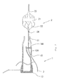
- Fig. 1 is a plan view showing one example of the sheath unit for recovering the thrombus capture member according to the present invention.
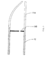
- Fig. 2 is a plan view showing another embodiment of the sheath unit according to the present invention.
- Fig. 3 - Fig. 5 are sectional views showing various shapes of a tip flexible tube.
- Fig. 6 is a plan view showing an action state of the sheath unit for recovering the thrombus capture member according to the present invention
- Fig. 7 is a plan view showing an action state of another implementation mode of the sheath unit for recovering the thrombus capture member according to the present invention.
- a sheath unit 1 for recovering a thrombus capture member which is shown in Fig. 1, is constituted by a tip flexible tube 11, a sheath 12, and an occlusion member 13 in a base end part.
- a stopper 14 is provided inside the sheath unit. Since it is important that the sheath 12 is a biocompatibile member having flexibility, it is a hollow tubular member comprising a synthetic resin such as, e.g., polyurethane, polyethylene, polyester, polypropylene, polyamide, polytetrafluoroethylene, and polyvinylidene fluoride.
- a synthetic resin such as, e.g., polyurethane, polyethylene, polyester, polypropylene, polyamide, polytetrafluoroethylene, and polyvinylidene fluoride.
- a thrombus capture member 2 is provided outside of the tip flexible tube 11 of sheath unit 1 and, through a shaft 3 inserted through a lumen of the sheath unit 1 for recovering the thrombus capture member, there is constituted a thrombus capture catheter unit which is capable of accommodating the thrombus capture member 2 in the tip flexible tube 11.
- the thrombus capture member 2 is inserted into a tip portion of the tip flexible tube 11 so as to be capable of entering into the tip, and includes a filter part 21 for capturing the thrombus and a crossed wire member 22 resembling a net bag, in which plural wires spirally intersect or cross.
- the crossed wire member 22 has a shape in which its tip and base ends, which are made with the plural wires being spirally crossed, each converge and its intermediate portion bulges outwardly and, on a distal side including the bulged intermediate part of this crossed wire member, there is provided filter part 21.
- the diameter of the pores of the filter ranges from 50 ⁇ m1000 ⁇ m, desirably 50 ⁇ m - 500 ⁇ m, and most desirably 100 ⁇ m - 200 ⁇ m. If the pore diameter of the pores of the filter part is less than 50 ⁇ m, flow of blood is hindered and, if it exceeds 1000 ⁇ m, the filter part has no utility.
- the thrombus capture member 2 has at its tip or distal end a slide ring 23 and has at its base end a fixed ring 24 and, by means of the slide ring 23 and the fixed ring 24, its tip is slidably attached to the shaft 3 and its base end is fixed to the shaft 3. And, when the sheath unit 1 for recovering the thrombus capture member is slid in a distal direction in regard to the thrombus capture member 2, there are accommodated in the sheath unit 1 the crossed wire member 22 constituting the capture member and a portion of the filter part 21.
- the stopper 14 is a stopper regulating sliding of the fixed ring 24 that is a fixed part of the crossed wire member 22, and it is desirable that it is formed of a biocompatible synthetic resin havingflexibilitysuch as,e.g.,polyurethane, polyethylene, polyester, polypropylene, polyamide, polytetrafluoroethylene, and polyvinylidene fluoride.
- a biocompatible synthetic resin havingflexibility such as,e.g.,polyurethane, polyethylene, polyester, polypropylene, polyamide, polytetrafluoroethylene, and polyvinylidene fluoride.
- a shape memory alloy can be adopted, and generally there is adopted a Ni-Ti system alloy, a Cu-Zn-Al system alloy, or the like.
- the crossed wire part 22 is memorized in a shape (reversion shape) as shown in Fig. 1.
- the number of wires constituting the crossed wire member 22 is 8 - 16, desirably 8 - 14, and most desirably 8 - 12.
- an outer diameter of the crossed wire member 2 there is adopted, although not limited especially, an outer diameter of 3.0, 3.5, 4.0, 4.5, 5.0, 5.5, 6.0, 6.5, 7.0, 7.5, or 8.0 mm, and it is desirable to selectively choose it in compliance with a blood vessel diameter in the lesion part.
- the filter material is one which can be dissolved to form a solution into which the crossed wire member 22 can be immersed.
- a synthetic resin of a biocompatible material such as, e.g., polyurethane, polyethylene, polyester, polypropylene, polytetrafluoroethylene, or polyvinylidene fluoride.
- the occlusion member 13 is a member closing the base end part of the sheath unit 1 for recovering the thrombus capture member, and is a tubular member capable of being formed from a plastic such as polypropylene, ABS resin, polyvinyl chloride, polyethylene, and polyethylene terephthalate, or a metal such as stainless steel and brass.
- a hole 13a along an axis is provided such that the shaft 3 can be inserted.
- a constitution in which a side hole 15 into which the shaft 3 can be inserted is provided in a tip side side-wall of the sheath.
- a sheath 12A possessing a second lumen into which the thrombus capture member 2 can be inserted is made, and a stopper 14A is provided in this second lumen part.
- the tip flexible tube 11 is provided on a sheath tip, and it is desirable that it is formed desirably of a biocompatible synthetic resin havingflexibilitysuch as,e.g.,polyurethane, polyethylene, polyester, polypropylene, polyamide, polytetrafluoroethylene, and polyvinylidene fluoride.
- the tube length of the tip flexible tube 11 that is a tubular member having a lumen is, although not limited especially, 1.0 - 50 mm, desirably 1 - 25 mm, and most desirably in the order of 5 - 15 mm.
- the tip flexible tube 11 is made into a shape in which its tip part is diameter-reduced, and acts so as to slightly deflate an opening part of the filter part 21 that is opened like a parachute, when the fixed ring 24 is stopped by abutting against the stopper 14 when the thrombus capture member 2 is accommodated into the sheath unit 1 for recovering the thrombus capture member. Therefore, it is possible to obtain the sheath unit 1 for recovering the thrombus capture member, in which there is no possibility that the filter part 21 for capturing the thrombus or the like is pressed strongly, and there is no possibility that the captured object leaks into the blood vessel from the pores of the filter. Additionally, if there is made a catheter having the tip flexible tube 11, the lesion part passing ability in the blood vessel is raised, and it is possible to obtain a thrombus capture catheter unit in which a certain recovery of the recovered, captured object is possible.
- the tip flexible tube 11 it is important that it have a shape in which the filter part 21 for capturing the thrombus can be accommodated without stress, and that the tip is diameter-reduced. Therefore, its opening may deviate from an axis of the lumen as shown in Fig. 3, or there may be such a shape having a circular opening in its tip as shown in Fig. 4, or such a shape in which an intermediate portion of the tube is diameter-reduced as shown in Fig. 5.
- a stopper 14B which opening is similarly provided in an eccentric position.
- a stopper 14 having an opening part in its center.
- Fig. 6 illustrates a method of recovering, after percutaneous angioplasty, the thrombus capture member, which has captured a thrombus or the like, into the sheath unit for recovering.
- the sheath unit 1 for recovering the capture member By sliding the sheath unit 1 for recovering the capture member, through which the shaft 3 is inserted, to the distal side, the intersection wire member 22 constituting the thrombus capture member 2 and a portion of the filter part 21 can be accommodated in the tip flexible tube 11.
- the stopper 14 provided in the sheath unit regulates, in an inside of the sheath unit, an excessive sliding of the fixed ring 24, that is the fixed part of the crossed wire member, to a base end side without impeding the sliding of the shaft 3.
- an accommodation position of the thrombus capture member 2 can be singly determined.
- the stopper 14 is formed of a biocompatible synthetic resin having flexibility. Further, its shape is not limited to the disc-like stopper 14 in the sheath unit, and it is also possible to use the above-mentioned stoppers 14A, 14B, or a stopper 14C whose part against the fixed ring 24 is tubular as shown in Fig. 7.
- the tip flexible tube whose tip opening portion is diameter-reduced when the thrombus capture member is accommodated in the sheath unit and a stop position of the member is regulated by the stopper, the tip flexible tube and the crossed wire member and the filter portion, which are mutually flexible, about, and thus the latter two are accommodated at predetermined accurate positions while being elastically deformed. Therefore, it follows that, in the inside of the sheath unit, the intersection wire member 22 and a portion of the filter part 21 are correctly accommodated in the predetermined positions, and there can be provided a constitution in which an accommodated object, such as a thrombus, captured by the filter part 21 is neither squeezed by the pores of the filter nor leaks.
- the sheath unit for recovering the capture member which is concerned with the present invention, has a constitution in which the tip flexible tube is provided on the tip part of the sheath, and the crossed wire member constituting the thrombus capture member and a portion of the filter part are accommodated in the tip flexible tube when the thrombus capture member is accommodated in the sheath, thereby diameter-reducing the opening part of the filter, the thrombus capture member can be recovered in the diameter-reduced portion of the sheath unit.
- the opening part of the filter which captures the thrombus or the like is deflated and no stress is applied thereto, there is obtained a sheath unit for recovering a thrombus capture member, which can remove the captured thrombus from the body without leaking.
- a thrombus capture catheter unit in which a sheath unit for recovering the thrombus capture member and the thrombus capture member are combined, the capture member taking in the thrombus can be recovered in a fine diameter sheath, and it becomes possible to remove the capturedthrombus from the body without leaking. Additionally, since there is possessed the tip flexible tube, a lesion part passing ability in the blood vessel is increased, and a certain recovery of the recovered, captured object becomes possible. Further, by this fact, it is possible to reduce a patient's physical and psychological burdens.
- thrombus capture member in which thrombus was captured, by a fine diameter sheath, and it becomes possible to remove the captured thrombus from the body without leaking. Further, by this fact, it is possible to reduce a patient's physical andpsychologicalburdens. Additionally, alesionpartpassing ability in the blood vessel in which the catheter unit is used is raised, and a certain or sure recovery of the recovered, captured object becomes possible.
Landscapes
- Health & Medical Sciences (AREA)
- Cardiology (AREA)
- Oral & Maxillofacial Surgery (AREA)
- Transplantation (AREA)
- Engineering & Computer Science (AREA)
- Biomedical Technology (AREA)
- Heart & Thoracic Surgery (AREA)
- Vascular Medicine (AREA)
- Life Sciences & Earth Sciences (AREA)
- Animal Behavior & Ethology (AREA)
- General Health & Medical Sciences (AREA)
- Public Health (AREA)
- Veterinary Medicine (AREA)
- Surgical Instruments (AREA)
- Media Introduction/Drainage Providing Device (AREA)
Abstract
Description
- The present invention relates to a sheath for recovering a thrombus capture member and a thrombus capture catheter, which capture a thrombus or the like which is freed when performing a percutaneous angioplasty in a hemadostenosis part of coronary artery, carotid artery, venous graft or the like.
- Hitherto, in the hemadostenosis part of coronary artery, carotid artery, venous graft or the like, there is performed a percutaneous angioplasty such as stent and POBA (Plain Old Balloon Atherectomy). This operation is one of circulation reconstruction surgeries for ensuring flow of blood by performing a stent detention or a balloon expansion in the hemadostenosis part, and achieves a desired result.
- However, in the above method, although the constriction part is expanded, a plaque (torose pathological piece), thrombus or the like, which is freed during the operation, flows to a lesion part periphery side, and thus induces an infarction, a No-Reflow phenomenon or the like, so that there is the fact that re-perfusion is not obtained. And, it is frequent that a complication induced by such thrombus or the like is a critical one.
- For example, in an unstable angina pectoris, an acute cardiac infarction or the like, to which the thrombus in the coronary artery relates, there is the fact that the thrombus is pushed out by the stent detention or the balloon expansion, so that a blood vessel in the lesion part periphery side is occluded. As a result, sufficient oxygen and nutrition are not supplied to a cardiac muscle, thereby inducing a cardiac muscle disorder such as cardiac muscle necrosis. Further, similarly, if a blood vessel supplying blood to a brain clogs, a so-called cerebral infarction is induced, and brain tissue dies.
- Especially, the carotid artery is liable to generate a constriction by an arterial sclerosis, so that the blood flow to the brain becomes insufficient, and a cerebral infarction is liable to occur by the thrombus formed in the constriction part. As a symptom of such cerebral infarction, there is paralysis, numbness, aphasia, disturbance of consciousness, or the like, and as to a function once lost it is impossible to expect a recuperation of 100% even if rehabilitation is performed, so that a great influence is exerted on a patient' s life thereafter. Further, since a large amount of thrombus adheres to an old transformed venous graft constriction part, caution is required.
- Like this, since the infarction caused by the thrombus induces the critical complication, and protection is required in the lesion part periphery side in percutaneous angioplasty, there is already a patent application for a catheter possessing a thrombus capture member (e.g., refer to
EP 1 402 826 A2 ). - When recovering the capture member for capturing thrombus and plaque described in
EP 1 402 826 A2 , as the sheath unit for recovering the capture member there is adopted a sheath whose diameter is the same as the sheath used for delivery or larger than the sheath used for deliverry. Here, in a case where a sheath is used having a diameter approximately the same as the sheath for delivery, although it can reach a distal lesion similar to the sheath concerned, since the capture member which captures the thrombus or the like is required to undergo, at the time of recovery, a change of shape in the sheath to have the compressed form as before expansion, there is a possibility that, before the capture member is from the body, the capture member is pressed, and a captured object leaks into the blood vessel from a pore of the filter of the capture member. - On the other hand, in a case where there is used a sheath whose diameter is larger than the sheath used for delivery, although the capture member with the captured thrombus can be accommodated in the sheath without undergoing the stress of compression a bore diameter in a tip side also becomes large, and such issues occur that reaching the distal lesion which the sheath for delivery can reach becomes difficult, that the sheath becomes liable to undergo an influence of shaft bias in a curred portion of the blood vessel and thus is caught by a stent strut, and that an inner wall of a curved blood vessel is damaged or injured.
- Whereupon, there is desired a sheath unit for recovery, in which a compression stress is not exerted on the capture member after recovering a thrombus, and additionally whose diameter is the same as the diameter of the sheath for delivery of the capture member.
- In view of the above issues, objects of the present invention are to provide a sheath unit for recovering a thrombus capture member, in which the thrombus capture member can be accommodated without leakage of the thrombus, and which can be more smoothlypassed though a lesion, and to provide a thrombus capture catheter unit which captures freed thrombus and the like.
- According to the invention, these objects are achieved by a sheath unit as defined in claim 1 and a thrombus capture catheter unit as defined in claim 4. The dependent claims define preferred and advantageous embodiments of the invention.
- In order to achieve the above objects, the invention concerned with a first aspect of the invention is a sheath unit for recovering a thrombus capture member, in which, in a tip part of a sheath having a lumen penetrating from its base end to its tip, there is provided a flexible tube (sometimes referred to herein as the tip flexible tube) in which one part of the tube or a tip opening part of the tube is reduced in diameter (hereinafter sometimes described as diameter-reduced).
- According to the first aspect of the invention having the above constitution or arrangement, because a diameter-reduced part of the tip for deflating an opening part of the thrombus capture member for capturing a thrombus or the like has flexibility when the thrombus capture member is accommodated into the sheath unit, it is possible to provide a sheath unit for recovering the thrombus capture member which softly grasps the thrombus capture member and in which no substance accommodated in the thrombus capture member leaks into the blood vessel.
- The invention concerned with a second aspect of the invention is characterized by a constitution in which the thrombus capture member is capable of entering into a tip of the flexible tube, the thrombus capture member includes a spindle shape, crossed wire member whose tip and base ends, in which plural wires spirally cross, each converge and whose intermediate portion bulges, and a parachute-like filter part in which a filter material is cover-fixed to (i.e., covers) an end part corresponding approximately to a half of the spindle shape, and, when the thrombus capture member is accommodated into the tip flexible tube, the crossed wire member constituting the thrombus capture member and a portion of the filter part are accommodated in the tip flexible tube, thereby reducing the diameter of an opening part of the filter part.
- According to the second aspect of the invention having the above constitution, since the diameter-reduced part for deflating the opening part of the filter part which captures the thrombus or the like has flexibility, when the thrombus capture member is accommodated into the sheath, the thrombus capture member is not pressed and the captured object does not leak into the blood vessel from pores of the filter. Additionally, it is possible to deflate the opening part of the filter part by the diameter-reducedpart having flexibility, and it is possible to obtain a sheath unit for recovering the thrombus capture member, which can certainly accommodate the accommodated object without leaking.
- The invention concerned with a third aspect of the invention is characterized in that in the sheath unit there is provided a stopper for regulating an accommodation position of the thrombus capture member.
- According to the third aspect of the invention having the above constitution, it is possible to always accommodate the thrombus capture member in an accurate position, and it is possible to obtain a sheath unit for recovering the thrombus capture member, which can accommodate the thrombus capture member under a state of no stress without pressing the thrombus capture member more than a necessary.
- The invention concerned with a fourth aspect of the invention is a thrombus capture catheter unit characterized as including a sheath unit having a sheath having a lumen penetrating from its base end to its tip, a flexible shaft inserted so as to be capable of advancing and retreating in an inside of the sheath unit, and a thrombus capture member provided at a tip portion of the shaft and inserted so as to be capable of entering into the tip portion of the sheath from the tip, wherein the thrombus capture member includes a spindle shape, crossed wire member whose tip and base ends, in which plural wires spirally cross, each converge and whose intermediate portion bulges, and a parachute-like filter part in which a filter material is cover-fixed to (i.e., covers) a distal side of the crossed wire member corresponding approximately to half of the spindle shape, and the sheath is a sheath for recovering a thrombus capture member having a constitution in which a tip flexible tube is provided in a tip part of the sheath, and, when the thrombus capture member is accommodated into the sheath, the crossed wire member constituting the thrombus capture member and a portion of the filter part are accommodated in the tip flexible tube, thereby reducing the diameter of an opening part of the filter part.
- According to the fourth aspect of the invention having the above constitution, since the diameter-reduced part for deflating the opening part of the filter part which captures the thrombus or the like has flexibility, when the thrombus capture member is accommodated into the sheath unit, the thrombus capture member is not pressed and the captured object does not leak into the blood vessel from the pores of the filter. Additionally, it is possible to deflate the opening part of the filter part by the diameter-reducedpart having flexibility, and it is possible to obtain a thrombus capture catheter unit which can certainly accommodate the accommodated object without leaking.
- The invention concerned with a fifth aspect of the invention is characterized by having a constitution in which the thrombus capture member possesses in its tip (or distal) end a slide ring and possesses in its base (or proximal) end a fixed ring, and when the sheath is slid to a distal side a stopper provided in the sheath unit is near the fixed ring and the crossed wire member constituting the thrombus capture member and one part of the filter part are accommodated in the tip flexible tube.
- According to the fifth aspect of the invention having the above constitution, it is possible to always accommodate the thrombus capture member in a accurate position, and it is possible to accommodate the thrombus capture member without pressing it more than necessary, under a state of having no stress, and without leakage of the accommodated object.
-
- Fig. 1 is a plan view showing one example of a sheath unit for recovering a capture member according to the present invention.
- Fig. 2 is a plan view showing another embodiment of the sheath unit for recovering the capture member.
- Fig. 3 is a sectional view showing various shapes of the tip flexible tube.
- Fig. 4 is a sectional view showing various shapes of the tip flexible tube.
- Fig. 5 is a sectional view showing various shapes of the tip flexible tube.
- Fig. 6 is a plan view showing an action state of the sheath unit for recovering the capture member according to the present invention
- Fig. 7 is a plan view showing an action state of another implementationmode of the sheath unit for recovering the capture member according to the present invention.
- Hereunder, implementation modes of a sheath unit for recovering the thrombus capture member and a thrombus capture catheter unit according to the present invention are explained in detail on the basis of Fig. 1 to Fig. 7.
- Fig. 1 is a plan view showing one example of the sheath unit for recovering the thrombus capture member according to the present invention. Fig. 2 is a plan view showing another embodiment of the sheath unit according to the present invention. Fig. 3 - Fig. 5 are sectional views showing various shapes of a tip flexible tube. Fig. 6 is a plan view showing an action state of the sheath unit for recovering the thrombus capture member according to the present invention, and Fig. 7 is a plan view showing an action state of another implementation mode of the sheath unit for recovering the thrombus capture member according to the present invention.
- A sheath unit 1 for recovering a thrombus capture member, which is shown in Fig. 1, is constituted by a tip
flexible tube 11, asheath 12, and anocclusion member 13 in a base end part. - Further, a
stopper 14 is provided inside the sheath unit. Since it is important that thesheath 12 is a biocompatibile member having flexibility, it is a hollow tubular member comprising a synthetic resin such as, e.g., polyurethane, polyethylene, polyester, polypropylene, polyamide, polytetrafluoroethylene, and polyvinylidene fluoride. - A
thrombus capture member 2 is provided outside of the tipflexible tube 11 of sheath unit 1 and, through ashaft 3 inserted through a lumen of the sheath unit 1 for recovering the thrombus capture member, there is constituted a thrombus capture catheter unit which is capable of accommodating thethrombus capture member 2 in the tipflexible tube 11. - The
thrombus capture member 2 is inserted into a tip portion of the tipflexible tube 11 so as to be capable of entering into the tip, and includes afilter part 21 for capturing the thrombus and a crossedwire member 22 resembling a net bag, in which plural wires spirally intersect or cross. Thecrossed wire member 22 has a shape in which its tip and base ends, which are made with the plural wires being spirally crossed, each converge and its intermediate portion bulges outwardly and, on a distal side including the bulged intermediate part of this crossed wire member, there is providedfilter part 21. Here, the diameter of the pores of the filter ranges from 50 µm1000 µm, desirably 50 µm - 500 µm, and most desirably 100 µm - 200 µm. If the pore diameter of the pores of the filter part is less than 50 µm, flow of blood is hindered and, if it exceeds 1000 µm, the filter part has no utility. - The
thrombus capture member 2 has at its tip or distal end aslide ring 23 and has at its base end afixed ring 24 and, by means of theslide ring 23 and the fixedring 24, its tip is slidably attached to theshaft 3 and its base end is fixed to theshaft 3. And, when the sheath unit 1 for recovering the thrombus capture member is slid in a distal direction in regard to thethrombus capture member 2, there are accommodated in the sheath unit 1 thecrossed wire member 22 constituting the capture member and a portion of thefilter part 21. - The
stopper 14 is a stopper regulating sliding of the fixedring 24 that is a fixed part of thecrossed wire member 22, and it is desirable that it is formed of a biocompatible synthetic resin havingflexibilitysuch as,e.g.,polyurethane, polyethylene, polyester, polypropylene, polyamide, polytetrafluoroethylene, and polyvinylidene fluoride. - As a material of the wire of the
crossed wire member 22, a shape memory alloy can be adopted, and generally there is adopted a Ni-Ti system alloy, a Cu-Zn-Al system alloy, or the like. In a case where the shape memory alloy is adopted as the material forming the wire, usually thecrossed wire part 22 is memorized in a shape (reversion shape) as shown in Fig. 1. In order to be applied to a lesion part in which there are many thrombi or the like, it is also possible to form a longer crossed wire member so as to be capable of capturing more of the thrombis. Further, the number of wires constituting thecrossed wire member 22 is 8 - 16, desirably 8 - 14, and most desirably 8 - 12. - Incidentally, as an outer diameter of the
crossed wire member 2, there is adopted, although not limited especially, an outer diameter of 3.0, 3.5, 4.0, 4.5, 5.0, 5.5, 6.0, 6.5, 7.0, 7.5, or 8.0 mm, and it is desirable to selectively choose it in compliance with a blood vessel diameter in the lesion part. - It is desirable that the filter material is one which can be dissolved to form a solution into which the
crossed wire member 22 can be immersed. Desirably, there is enumerated a synthetic resin of a biocompatible material such as, e.g., polyurethane, polyethylene, polyester, polypropylene, polytetrafluoroethylene, or polyvinylidene fluoride. - The
occlusion member 13 is a member closing the base end part of the sheath unit 1 for recovering the thrombus capture member, and is a tubular member capable of being formed from a plastic such as polypropylene, ABS resin, polyvinyl chloride, polyethylene, and polyethylene terephthalate, or a metal such as stainless steel and brass. - Although a base end of the
occlusion member 13 is closed, ahole 13a along an axis is provided such that theshaft 3 can be inserted. - Further, as shown in Fig. 2, it is also possible to make a constitution in which a
side hole 15 into which theshaft 3 can be inserted is provided in a tip side side-wall of the sheath. In this example, there is made asheath 12A possessing a second lumen into which thethrombus capture member 2 can be inserted, and astopper 14A is provided in this second lumen part. - The tip
flexible tube 11 is provided on a sheath tip, and it is desirable that it is formed desirably of a biocompatible synthetic resin havingflexibilitysuch as,e.g.,polyurethane, polyethylene, polyester, polypropylene, polyamide, polytetrafluoroethylene, and polyvinylidene fluoride. The tube length of the tipflexible tube 11 that is a tubular member having a lumen is, although not limited especially, 1.0 - 50 mm, desirably 1 - 25 mm, and most desirably in the order of 5 - 15 mm. - The tip
flexible tube 11 is made into a shape in which its tip part is diameter-reduced, and acts so as to slightly deflate an opening part of thefilter part 21 that is opened like a parachute, when the fixedring 24 is stopped by abutting against thestopper 14 when thethrombus capture member 2 is accommodated into the sheath unit 1 for recovering the thrombus capture member. Therefore, it is possible to obtain the sheath unit 1 for recovering the thrombus capture member, in which there is no possibility that thefilter part 21 for capturing the thrombus or the like is pressed strongly, and there is no possibility that the captured object leaks into the blood vessel from the pores of the filter. Additionally, if there is made a catheter having the tipflexible tube 11, the lesion part passing ability in the blood vessel is raised, and it is possible to obtain a thrombus capture catheter unit in which a certain recovery of the recovered, captured object is possible. - Further, as to the tip
flexible tube 11, it is important that it have a shape in which thefilter part 21 for capturing the thrombus can be accommodated without stress, and that the tip is diameter-reduced. Therefore, its opening may deviate from an axis of the lumen as shown in Fig. 3, or there may be such a shape having a circular opening in its tip as shown in Fig. 4, or such a shape in which an intermediate portion of the tube is diameter-reduced as shown in Fig. 5. In a case of a tipflexible tube 11A as shown in Fig. 3, which has an eccentric opening part whose center deviates from the axis of the lumen, there is adopted astopper 14B whose opening is similarly provided in an eccentric position. Further, in a case of a tipflexible tube 11B as shown in Fig. 4, having a circular opening in its tip, or a tip flexible tube 11C shown in Fig. 5 having a shape in which an intermediate portion of the tube is diameter-reduced, it is possible to use astopper 14 having an opening part in its center. - Next, referring to Fig. 6 and Fig. 7, there is explained an action state of the sheath unit for recovering the capture member.
- Fig. 6 illustrates a method of recovering, after percutaneous angioplasty, the thrombus capture member, which has captured a thrombus or the like, into the sheath unit for recovering. By sliding the sheath unit 1 for recovering the capture member, through which the
shaft 3 is inserted, to the distal side, theintersection wire member 22 constituting thethrombus capture member 2 and a portion of thefilter part 21 can be accommodated in the tipflexible tube 11. - When accommodating the thrombus capture member, most of the
filter part 21 exists outside of the tipflexible tube 11, and the captured object is not pressed. Further, thestopper 14 provided in the sheath unit regulates, in an inside of the sheath unit, an excessive sliding of the fixedring 24, that is the fixed part of the crossed wire member, to a base end side without impeding the sliding of theshaft 3. By this slide regulation, an accommodation position of thethrombus capture member 2 can be singly determined. - As mentioned above, it is desirable that the
stopper 14 is formed of a biocompatible synthetic resin having flexibility. Further, its shape is not limited to the disc-like stopper 14 in the sheath unit, and it is also possible to use the above-mentionedstoppers stopper 14C whose part against the fixedring 24 is tubular as shown in Fig. 7. - Accordingly, there is provided a constitution in which, by using the tip flexible tube whose tip opening portion is diameter-reduced, when the thrombus capture member is accommodated in the sheath unit and a stop position of the member is regulated by the stopper, the tip flexible tube and the crossed wire member and the filter portion, which are mutually flexible, about, and thus the latter two are accommodated at predetermined accurate positions while being elastically deformed. Therefore, it follows that, in the inside of the sheath unit, the
intersection wire member 22 and a portion of thefilter part 21 are correctly accommodated in the predetermined positions, and there can be provided a constitution in which an accommodated object, such as a thrombus, captured by thefilter part 21 is neither squeezed by the pores of the filter nor leaks. - As described above, since the sheath unit for recovering the capture member, which is concerned with the present invention, has a constitution in which the tip flexible tube is provided on the tip part of the sheath, and the crossed wire member constituting the thrombus capture member and a portion of the filter part are accommodated in the tip flexible tube when the thrombus capture member is accommodated in the sheath, thereby diameter-reducing the opening part of the filter, the thrombus capture member can be recovered in the diameter-reduced portion of the sheath unit. Further, since the opening part of the filter which captures the thrombus or the like is deflated and no stress is applied thereto, there is obtained a sheath unit for recovering a thrombus capture member, which can remove the captured thrombus from the body without leaking.
- Therefore, since there is provided a thrombus capture catheter unit in which a sheath unit for recovering the thrombus capture member and the thrombus capture member are combined, the capture member taking in the thrombus can be recovered in a fine diameter sheath, and it becomes possible to remove the capturedthrombus from the body without leaking. Additionally, since there is possessed the tip flexible tube, a lesion part passing ability in the blood vessel is increased, and a certain recovery of the recovered, captured object becomes possible. Further, by this fact, it is possible to reduce a patient's physical and psychological burdens.
- According to the present invention, it is possible to recover a thrombus capture member, in which thrombus was captured, by a fine diameter sheath, and it becomes possible to remove the captured thrombus from the body without leaking. Further, by this fact, it is possible to reduce a patient's physical andpsychologicalburdens. Additionally, alesionpartpassing ability in the blood vessel in which the catheter unit is used is raised, and a certain or sure recovery of the recovered, captured object becomes possible.
Claims (5)
- A sheath unit for recovering a thrombus capture member, said sheath unit (1) comprising a sheath (12; 12A) having a lumen penetrating from a base end to a tip end of the sheath (12; 12A) and having a flexible tube (11; 11B; 11C) at the tip end, one part of the flexible tube (11; 11B; 11C) or a tip opening of the flexible tube (11; 11B; 11C) being diameter-reduced.
- The sheath unit for recovering a thrombus capture member of claim 1, wherein the thrombus capture member (2) is capable of entering into a tip of the flexible tube (11; 11B; 11C) and comprises a spindle shape crossed wire member (22) comprising a plurality of spirally arranged crossing wires converging at tip and base ends of the wire member (22) and bulging in an intermediate portion of the wire member (22), and a parachute-likefilterpart (21) inwhicha filtermaterial covers an end part of the wire member (22) corresponding to about a half of the spindle shape wherein, when the thrombus capture member (2) is accommodated into the flexible tube (11; 11B; 11C), the crossed wire member (22) of the thrombus capture member (2) and a portion of the filter part (21) are accommodated in the flexible tube (11; 11B; 11C), thereby diameter-reducing an opening end of the filter part (21).
- The sheath unit for recovering a thrombus capture member according to claim 1 or 2, characterized in that in the sheath (12; 12A) there is provided a stopper (14; 14A; 14B; 14C) for regulating an accommodation position of the thrombus capture member (2).
- A thrombus capture catheter unit comprising a sheath unit (1) comprising a sheath (12; 12A) having a lumen penetrating from a base end to a tip end of the sheath (12; 12A), a flexible shaft (3) inserted in the lumen so as to be capable of advancing and retreating in an inside of the sheath (12; 12A), and a thrombus capture member (2) provided at a tip portion of the shaft (3) and inserted so as to be capable of entering into a tip portion of the sheath (12; 12A), wherein the thrombus capture member (2) comprises a spindle shape crossed wire member (22) comprising a plurality of spirally arranged crossing wires converging at tip and base ends of the wire member (22) and bulging in an intermediate portion of the wire member (22), and a parachute-likefilterpart (21) inwhicha filtermaterial covers an end part of the wire member (22) corresponding to about a half of the spindle shape wherein, when the thrombus capture member (2) is accommodated into a flexible tube (11; 11B; 11C) of the sheath unit (1), the crossed wire member (22) of the thrombus capture member (2) and a portion of the filter part (21) are accommodated in the flexible tube (11; 11B; 11C), thereby diameter-reducing an opening end of the filter part (21) .
- A thrombus capture catheter unit according to claim 4, wherein the thrombus capture member has at its distal end a slide ring (23) and has at its base end a fixed ring (24), and wherein a stopper (14; 14A; 14B; 14C) is provided in the sheath (12; 12A) and when the sheath (12; 12A) is slid in a distal direction the stopper (14; 14A; 14B; 14C) near the fixed ring (24) and the crossed wire member (22) constituting the thrombus capture member (2) and a portion of the filter part (21) are accommodated in the tip flexible tube (11; 11B; 11C) .
Applications Claiming Priority (1)
| Application Number | Priority Date | Filing Date | Title |
|---|---|---|---|
| JP2006210387A JP4483835B2 (en) | 2006-08-01 | 2006-08-01 | Thrombus capture member recovery sheath and thrombus capture catheter |
Publications (2)
| Publication Number | Publication Date |
|---|---|
| EP1884218A1 true EP1884218A1 (en) | 2008-02-06 |
| EP1884218B1 EP1884218B1 (en) | 2012-04-25 |
Family
ID=38514306
Family Applications (1)
| Application Number | Title | Priority Date | Filing Date |
|---|---|---|---|
| EP07113491A Active EP1884218B1 (en) | 2006-08-01 | 2007-07-31 | Sheath unit for recovering thrombus capture member and thrombus capture catheter unit |
Country Status (4)
| Country | Link |
|---|---|
| US (1) | US20080033483A1 (en) |
| EP (1) | EP1884218B1 (en) |
| JP (1) | JP4483835B2 (en) |
| AT (1) | ATE554728T1 (en) |
Cited By (1)
| Publication number | Priority date | Publication date | Assignee | Title |
|---|---|---|---|---|
| CN109498206A (en) * | 2018-12-06 | 2019-03-22 | 深圳市科奕顿生物医疗科技有限公司 | Implant recycles instrument and its application and packaging |
Families Citing this family (4)
| Publication number | Priority date | Publication date | Assignee | Title |
|---|---|---|---|---|
| JP5326313B2 (en) * | 2008-03-21 | 2013-10-30 | ニプロ株式会社 | Thrombus capture catheter |
| JP6602292B2 (en) | 2014-05-09 | 2019-11-06 | 東レ株式会社 | Endovascular treatment aid |
| EP3141191A4 (en) | 2014-05-09 | 2018-04-04 | Toray Industries, Inc. | Endovascular treatment assistance tool |
| CN110680459A (en) * | 2019-11-08 | 2020-01-14 | 刘昌伟 | Embolectomy device for arterial and venous thrombosis |
Citations (4)
| Publication number | Priority date | Publication date | Assignee | Title |
|---|---|---|---|---|
| WO2002040090A1 (en) * | 2000-11-01 | 2002-05-23 | Thielen Joseph M | Distal protection and delivery system and method |
| WO2003004075A2 (en) * | 2001-07-02 | 2003-01-16 | Rubicon Medical, Inc. | Methods, systems, and devices for deploying an embolic protection filter |
| US20040039412A1 (en) * | 2002-08-20 | 2004-02-26 | Takaaki Isshiki | Thrombus capture catheter |
| WO2006102546A1 (en) * | 2005-03-24 | 2006-09-28 | Cook Incorporated | Exchangeable delivery system with distal protection |
Family Cites Families (7)
| Publication number | Priority date | Publication date | Assignee | Title |
|---|---|---|---|---|
| US6171327B1 (en) * | 1999-02-24 | 2001-01-09 | Scimed Life Systems, Inc. | Intravascular filter and method |
| DE69939753D1 (en) * | 1999-08-27 | 2008-11-27 | Ev3 Inc | Movable vascular filter |
| US6325815B1 (en) * | 1999-09-21 | 2001-12-04 | Microvena Corporation | Temporary vascular filter |
| US6679902B1 (en) * | 2000-07-19 | 2004-01-20 | Advanced Cardiovascular Systems, Inc. | Reduced profile delivery sheath for use in interventional procedures |
| US6616681B2 (en) * | 2000-10-05 | 2003-09-09 | Scimed Life Systems, Inc. | Filter delivery and retrieval device |
| US6979343B2 (en) * | 2001-02-14 | 2005-12-27 | Ev3 Inc. | Rolled tip recovery catheter |
| US7226464B2 (en) * | 2001-03-01 | 2007-06-05 | Scimed Life Systems, Inc. | Intravascular filter retrieval device having an actuatable dilator tip |
-
2006
- 2006-08-01 JP JP2006210387A patent/JP4483835B2/en active Active
-
2007
- 2007-07-31 AT AT07113491T patent/ATE554728T1/en active
- 2007-07-31 EP EP07113491A patent/EP1884218B1/en active Active
- 2007-07-31 US US11/882,267 patent/US20080033483A1/en not_active Abandoned
Patent Citations (5)
| Publication number | Priority date | Publication date | Assignee | Title |
|---|---|---|---|---|
| WO2002040090A1 (en) * | 2000-11-01 | 2002-05-23 | Thielen Joseph M | Distal protection and delivery system and method |
| WO2003004075A2 (en) * | 2001-07-02 | 2003-01-16 | Rubicon Medical, Inc. | Methods, systems, and devices for deploying an embolic protection filter |
| US20040039412A1 (en) * | 2002-08-20 | 2004-02-26 | Takaaki Isshiki | Thrombus capture catheter |
| EP1402826A2 (en) | 2002-08-20 | 2004-03-31 | Nipro Corporation | Thrombus capture catheter |
| WO2006102546A1 (en) * | 2005-03-24 | 2006-09-28 | Cook Incorporated | Exchangeable delivery system with distal protection |
Cited By (1)
| Publication number | Priority date | Publication date | Assignee | Title |
|---|---|---|---|---|
| CN109498206A (en) * | 2018-12-06 | 2019-03-22 | 深圳市科奕顿生物医疗科技有限公司 | Implant recycles instrument and its application and packaging |
Also Published As
| Publication number | Publication date |
|---|---|
| JP4483835B2 (en) | 2010-06-16 |
| JP2008035923A (en) | 2008-02-21 |
| EP1884218B1 (en) | 2012-04-25 |
| US20080033483A1 (en) | 2008-02-07 |
| ATE554728T1 (en) | 2012-05-15 |
Similar Documents
| Publication | Publication Date | Title |
|---|---|---|
| EP1402826B1 (en) | Thrombus capture catheter | |
| US20090240213A1 (en) | Shaft for operating a blood thrombus capturing member, and blood thrombus capturing catheter | |
| US6616682B2 (en) | Methods and apparatus for distal protection during a medical procedure | |
| US20020183781A1 (en) | Catheter | |
| JP2004097807A (en) | Thrombus capture catheter | |
| CA2517621C (en) | Clot retrieval device | |
| US8388644B2 (en) | Embolic protection device and method of use | |
| US20030083692A1 (en) | Distal protection device and method of use thereof | |
| US20090240238A1 (en) | Clot Retrieval Mechanism | |
| US20140194972A1 (en) | Catheter | |
| EP1884218B1 (en) | Sheath unit for recovering thrombus capture member and thrombus capture catheter unit | |
| AU2002347928A1 (en) | Distal protection and retrieval device | |
| WO2015009655A1 (en) | High flow embolic protection device | |
| JP6806090B2 (en) | Synthetic resin stent | |
| JP2010517641A (en) | Device and method for closing a vascular opening using a permanent implant | |
| JP2008502451A (en) | Invertable intravascular filter | |
| EP2113280A1 (en) | System for providing embolic protection and removing embolic material | |
| JP2009178518A (en) | Medical tubular body, thrombus capture member recovery sheath, thrombus recovery catheter and balloon catheter | |
| EP2381889A1 (en) | Body lumen filters with large surface area anchors | |
| US9138306B2 (en) | Detachment mechanism for a central venous access filter and method of use | |
| JP2011036317A (en) | Protecting stent system | |
| JP2025145386A (en) | Catheter device and method for recovering object to be recovered | |
| CN119072276A (en) | Left atrial appendage closure device with central support | |
| IE20020279A1 (en) | A catheter |
Legal Events
| Date | Code | Title | Description |
|---|---|---|---|
| PUAI | Public reference made under article 153(3) epc to a published international application that has entered the european phase |
Free format text: ORIGINAL CODE: 0009012 |
|
| AK | Designated contracting states |
Kind code of ref document: A1 Designated state(s): AT BE BG CH CY CZ DE DK EE ES FI FR GB GR HU IE IS IT LI LT LU LV MC MT NL PL PT RO SE SI SK TR |
|
| AX | Request for extension of the european patent |
Extension state: AL BA HR MK YU |
|
| 17P | Request for examination filed |
Effective date: 20080709 |
|
| 17Q | First examination report despatched |
Effective date: 20080811 |
|
| AKX | Designation fees paid |
Designated state(s): AT BE BG CH CY CZ DE DK EE ES FI FR GB GR HU IE IS IT LI LT LU LV MC MT NL PL PT RO SE SI SK TR |
|
| R17C | First examination report despatched (corrected) |
Effective date: 20110302 |
|
| GRAP | Despatch of communication of intention to grant a patent |
Free format text: ORIGINAL CODE: EPIDOSNIGR1 |
|
| GRAS | Grant fee paid |
Free format text: ORIGINAL CODE: EPIDOSNIGR3 |
|
| GRAA | (expected) grant |
Free format text: ORIGINAL CODE: 0009210 |
|
| AK | Designated contracting states |
Kind code of ref document: B1 Designated state(s): AT BE BG CH CY CZ DE DK EE ES FI FR GB GR HU IE IS IT LI LT LU LV MC MT NL PL PT RO SE SI SK TR |
|
| REG | Reference to a national code |
Ref country code: GB Ref legal event code: FG4D |
|
| REG | Reference to a national code |
Ref country code: CH Ref legal event code: EP |
|
| RIN2 | Information on inventor provided after grant (corrected) |
Inventor name: FURUTA, NORIHIKO Inventor name: UMEGAKI, RYOTA Inventor name: MIYAGAWA, KATSUYA Inventor name: KATAISHI, YUICHI Inventor name: ISSHIKI, TAKAAKI |
|
| REG | Reference to a national code |
Ref country code: AT Ref legal event code: REF Ref document number: 554728 Country of ref document: AT Kind code of ref document: T Effective date: 20120515 |
|
| REG | Reference to a national code |
Ref country code: IE Ref legal event code: FG4D |
|
| REG | Reference to a national code |
Ref country code: DE Ref legal event code: R096 Ref document number: 602007022213 Country of ref document: DE Effective date: 20120621 |
|
| REG | Reference to a national code |
Ref country code: NL Ref legal event code: T3 |
|
| REG | Reference to a national code |
Ref country code: AT Ref legal event code: MK05 Ref document number: 554728 Country of ref document: AT Kind code of ref document: T Effective date: 20120425 |
|
| LTIE | Lt: invalidation of european patent or patent extension |
Effective date: 20120425 |
|
| PG25 | Lapsed in a contracting state [announced via postgrant information from national office to epo] |
Ref country code: SE Free format text: LAPSE BECAUSE OF FAILURE TO SUBMIT A TRANSLATION OF THE DESCRIPTION OR TO PAY THE FEE WITHIN THE PRESCRIBED TIME-LIMIT Effective date: 20120425 Ref country code: PL Free format text: LAPSE BECAUSE OF FAILURE TO SUBMIT A TRANSLATION OF THE DESCRIPTION OR TO PAY THE FEE WITHIN THE PRESCRIBED TIME-LIMIT Effective date: 20120425 Ref country code: IS Free format text: LAPSE BECAUSE OF FAILURE TO SUBMIT A TRANSLATION OF THE DESCRIPTION OR TO PAY THE FEE WITHIN THE PRESCRIBED TIME-LIMIT Effective date: 20120825 Ref country code: CY Free format text: LAPSE BECAUSE OF FAILURE TO SUBMIT A TRANSLATION OF THE DESCRIPTION OR TO PAY THE FEE WITHIN THE PRESCRIBED TIME-LIMIT Effective date: 20120425 Ref country code: LT Free format text: LAPSE BECAUSE OF FAILURE TO SUBMIT A TRANSLATION OF THE DESCRIPTION OR TO PAY THE FEE WITHIN THE PRESCRIBED TIME-LIMIT Effective date: 20120425 Ref country code: FI Free format text: LAPSE BECAUSE OF FAILURE TO SUBMIT A TRANSLATION OF THE DESCRIPTION OR TO PAY THE FEE WITHIN THE PRESCRIBED TIME-LIMIT Effective date: 20120425 |
|
| PG25 | Lapsed in a contracting state [announced via postgrant information from national office to epo] |
Ref country code: PT Free format text: LAPSE BECAUSE OF FAILURE TO SUBMIT A TRANSLATION OF THE DESCRIPTION OR TO PAY THE FEE WITHIN THE PRESCRIBED TIME-LIMIT Effective date: 20120827 Ref country code: LV Free format text: LAPSE BECAUSE OF FAILURE TO SUBMIT A TRANSLATION OF THE DESCRIPTION OR TO PAY THE FEE WITHIN THE PRESCRIBED TIME-LIMIT Effective date: 20120425 Ref country code: GR Free format text: LAPSE BECAUSE OF FAILURE TO SUBMIT A TRANSLATION OF THE DESCRIPTION OR TO PAY THE FEE WITHIN THE PRESCRIBED TIME-LIMIT Effective date: 20120726 Ref country code: SI Free format text: LAPSE BECAUSE OF FAILURE TO SUBMIT A TRANSLATION OF THE DESCRIPTION OR TO PAY THE FEE WITHIN THE PRESCRIBED TIME-LIMIT Effective date: 20120425 |
|
| PG25 | Lapsed in a contracting state [announced via postgrant information from national office to epo] |
Ref country code: BE Free format text: LAPSE BECAUSE OF FAILURE TO SUBMIT A TRANSLATION OF THE DESCRIPTION OR TO PAY THE FEE WITHIN THE PRESCRIBED TIME-LIMIT Effective date: 20120425 |
|
| PG25 | Lapsed in a contracting state [announced via postgrant information from national office to epo] |
Ref country code: EE Free format text: LAPSE BECAUSE OF FAILURE TO SUBMIT A TRANSLATION OF THE DESCRIPTION OR TO PAY THE FEE WITHIN THE PRESCRIBED TIME-LIMIT Effective date: 20120425 Ref country code: AT Free format text: LAPSE BECAUSE OF FAILURE TO SUBMIT A TRANSLATION OF THE DESCRIPTION OR TO PAY THE FEE WITHIN THE PRESCRIBED TIME-LIMIT Effective date: 20120425 Ref country code: DK Free format text: LAPSE BECAUSE OF FAILURE TO SUBMIT A TRANSLATION OF THE DESCRIPTION OR TO PAY THE FEE WITHIN THE PRESCRIBED TIME-LIMIT Effective date: 20120425 Ref country code: SK Free format text: LAPSE BECAUSE OF FAILURE TO SUBMIT A TRANSLATION OF THE DESCRIPTION OR TO PAY THE FEE WITHIN THE PRESCRIBED TIME-LIMIT Effective date: 20120425 Ref country code: CZ Free format text: LAPSE BECAUSE OF FAILURE TO SUBMIT A TRANSLATION OF THE DESCRIPTION OR TO PAY THE FEE WITHIN THE PRESCRIBED TIME-LIMIT Effective date: 20120425 Ref country code: RO Free format text: LAPSE BECAUSE OF FAILURE TO SUBMIT A TRANSLATION OF THE DESCRIPTION OR TO PAY THE FEE WITHIN THE PRESCRIBED TIME-LIMIT Effective date: 20120425 |
|
| PG25 | Lapsed in a contracting state [announced via postgrant information from national office to epo] |
Ref country code: MC Free format text: LAPSE BECAUSE OF NON-PAYMENT OF DUE FEES Effective date: 20120731 |
|
| REG | Reference to a national code |
Ref country code: CH Ref legal event code: PL |
|
| PLBE | No opposition filed within time limit |
Free format text: ORIGINAL CODE: 0009261 |
|
| STAA | Information on the status of an ep patent application or granted ep patent |
Free format text: STATUS: NO OPPOSITION FILED WITHIN TIME LIMIT |
|
| 26N | No opposition filed |
Effective date: 20130128 |
|
| PG25 | Lapsed in a contracting state [announced via postgrant information from national office to epo] |
Ref country code: ES Free format text: LAPSE BECAUSE OF FAILURE TO SUBMIT A TRANSLATION OF THE DESCRIPTION OR TO PAY THE FEE WITHIN THE PRESCRIBED TIME-LIMIT Effective date: 20120805 Ref country code: LI Free format text: LAPSE BECAUSE OF NON-PAYMENT OF DUE FEES Effective date: 20120731 Ref country code: CH Free format text: LAPSE BECAUSE OF NON-PAYMENT OF DUE FEES Effective date: 20120731 |
|
| REG | Reference to a national code |
Ref country code: IE Ref legal event code: MM4A |
|
| REG | Reference to a national code |
Ref country code: DE Ref legal event code: R097 Ref document number: 602007022213 Country of ref document: DE Effective date: 20130128 |
|
| PG25 | Lapsed in a contracting state [announced via postgrant information from national office to epo] |
Ref country code: BG Free format text: LAPSE BECAUSE OF FAILURE TO SUBMIT A TRANSLATION OF THE DESCRIPTION OR TO PAY THE FEE WITHIN THE PRESCRIBED TIME-LIMIT Effective date: 20120725 Ref country code: MT Free format text: LAPSE BECAUSE OF FAILURE TO SUBMIT A TRANSLATION OF THE DESCRIPTION OR TO PAY THE FEE WITHIN THE PRESCRIBED TIME-LIMIT Effective date: 20120425 Ref country code: IE Free format text: LAPSE BECAUSE OF NON-PAYMENT OF DUE FEES Effective date: 20120731 |
|
| PG25 | Lapsed in a contracting state [announced via postgrant information from national office to epo] |
Ref country code: TR Free format text: LAPSE BECAUSE OF FAILURE TO SUBMIT A TRANSLATION OF THE DESCRIPTION OR TO PAY THE FEE WITHIN THE PRESCRIBED TIME-LIMIT Effective date: 20120425 |
|
| PG25 | Lapsed in a contracting state [announced via postgrant information from national office to epo] |
Ref country code: LU Free format text: LAPSE BECAUSE OF NON-PAYMENT OF DUE FEES Effective date: 20120731 |
|
| PG25 | Lapsed in a contracting state [announced via postgrant information from national office to epo] |
Ref country code: HU Free format text: LAPSE BECAUSE OF FAILURE TO SUBMIT A TRANSLATION OF THE DESCRIPTION OR TO PAY THE FEE WITHIN THE PRESCRIBED TIME-LIMIT Effective date: 20070731 |
|
| REG | Reference to a national code |
Ref country code: FR Ref legal event code: PLFP Year of fee payment: 9 |
|
| REG | Reference to a national code |
Ref country code: FR Ref legal event code: PLFP Year of fee payment: 10 |
|
| REG | Reference to a national code |
Ref country code: FR Ref legal event code: PLFP Year of fee payment: 11 |
|
| REG | Reference to a national code |
Ref country code: FR Ref legal event code: PLFP Year of fee payment: 12 |
|
| PGFP | Annual fee paid to national office [announced via postgrant information from national office to epo] |
Ref country code: NL Payment date: 20250721 Year of fee payment: 19 |
|
| PGFP | Annual fee paid to national office [announced via postgrant information from national office to epo] |
Ref country code: DE Payment date: 20250722 Year of fee payment: 19 |
|
| PGFP | Annual fee paid to national office [announced via postgrant information from national office to epo] |
Ref country code: IT Payment date: 20250724 Year of fee payment: 19 |
|
| PGFP | Annual fee paid to national office [announced via postgrant information from national office to epo] |
Ref country code: GB Payment date: 20250722 Year of fee payment: 19 |
|
| PGFP | Annual fee paid to national office [announced via postgrant information from national office to epo] |
Ref country code: FR Payment date: 20250724 Year of fee payment: 19 |