EP1884072B1 - Externally sourced synchronized beacon - Google Patents
Externally sourced synchronized beacon Download PDFInfo
- Publication number
- EP1884072B1 EP1884072B1 EP06759073.7A EP06759073A EP1884072B1 EP 1884072 B1 EP1884072 B1 EP 1884072B1 EP 06759073 A EP06759073 A EP 06759073A EP 1884072 B1 EP1884072 B1 EP 1884072B1
- Authority
- EP
- European Patent Office
- Prior art keywords
- wireless access
- beacon
- broadcast signal
- signal
- broadcast
- Prior art date
- Legal status (The legal status is an assumption and is not a legal conclusion. Google has not performed a legal analysis and makes no representation as to the accuracy of the status listed.)
- Expired - Lifetime
Links
Images




Classifications
-
- H—ELECTRICITY
- H04—ELECTRIC COMMUNICATION TECHNIQUE
- H04W—WIRELESS COMMUNICATION NETWORKS
- H04W56/00—Synchronisation arrangements
- H04W56/001—Synchronization between nodes
- H04W56/0015—Synchronization between nodes one node acting as a reference for the others
-
- H—ELECTRICITY
- H04—ELECTRIC COMMUNICATION TECHNIQUE
- H04B—TRANSMISSION
- H04B7/00—Radio transmission systems, i.e. using radiation field
- H04B7/24—Radio transmission systems, i.e. using radiation field for communication between two or more posts
- H04B7/26—Radio transmission systems, i.e. using radiation field for communication between two or more posts at least one of which is mobile
- H04B7/2662—Arrangements for Wireless System Synchronisation
- H04B7/2671—Arrangements for Wireless Time-Division Multiple Access [TDMA] System Synchronisation
- H04B7/2678—Time synchronisation
- H04B7/2687—Inter base stations synchronisation
- H04B7/2693—Centralised synchronisation, i.e. using external universal time reference, e.g. by using a global positioning system [GPS] or by distributing time reference over the wireline network
-
- H—ELECTRICITY
- H04—ELECTRIC COMMUNICATION TECHNIQUE
- H04W—WIRELESS COMMUNICATION NETWORKS
- H04W48/00—Access restriction; Network selection; Access point selection
- H04W48/08—Access restriction or access information delivery, e.g. discovery data delivery
- H04W48/10—Access restriction or access information delivery, e.g. discovery data delivery using broadcasted information
-
- H—ELECTRICITY
- H04—ELECTRIC COMMUNICATION TECHNIQUE
- H04W—WIRELESS COMMUNICATION NETWORKS
- H04W48/00—Access restriction; Network selection; Access point selection
- H04W48/08—Access restriction or access information delivery, e.g. discovery data delivery
- H04W48/12—Access restriction or access information delivery, e.g. discovery data delivery using downlink control channel
-
- H—ELECTRICITY
- H04—ELECTRIC COMMUNICATION TECHNIQUE
- H04W—WIRELESS COMMUNICATION NETWORKS
- H04W36/00—Hand-off or reselection arrangements
- H04W36/16—Performing reselection for specific purposes
-
- H—ELECTRICITY
- H04—ELECTRIC COMMUNICATION TECHNIQUE
- H04W—WIRELESS COMMUNICATION NETWORKS
- H04W56/00—Synchronisation arrangements
-
- H—ELECTRICITY
- H04—ELECTRIC COMMUNICATION TECHNIQUE
- H04W—WIRELESS COMMUNICATION NETWORKS
- H04W74/00—Wireless channel access
-
- H—ELECTRICITY
- H04—ELECTRIC COMMUNICATION TECHNIQUE
- H04W—WIRELESS COMMUNICATION NETWORKS
- H04W84/00—Network topologies
- H04W84/02—Hierarchically pre-organised networks, e.g. paging networks, cellular networks, WLAN [Wireless Local Area Network] or WLL [Wireless Local Loop]
- H04W84/10—Small scale networks; Flat hierarchical networks
- H04W84/12—WLAN [Wireless Local Area Networks]
-
- H—ELECTRICITY
- H04—ELECTRIC COMMUNICATION TECHNIQUE
- H04W—WIRELESS COMMUNICATION NETWORKS
- H04W84/00—Network topologies
- H04W84/18—Self-organising networks, e.g. ad-hoc networks or sensor networks
Definitions
- the invention may be embodied as devices, systems, methods, and/or computer program products. Accordingly, some or all of the invention may be embodied in hardware and/or in software (including firmware, resident software, micro-code, state machines, gate arrays, etc.) Furthermore, the present invention may take the form of a computer program product on a computer-usable or computer-readable storage medium having computer-usable or computer-readable program code embodied in the medium for use by or in connection with an instruction execution system.
- a computer-usable or computer-readable medium may be any medium that can contain, store, communicate, propagate, or transport the program for use by or in connection with the instruction execution system, apparatus, or device.
- FIG. 1 illustrates an embodiment 100 showing a wireless network with overlapping coverage areas.
- a network controller 102 is connected to a network backbone 104. Connected to the backbone 104 are radio transceivers 106, 108, 110, and 112. Each radio transceiver has an antenna, such as antenna 109 connected to transceiver 108. Transceiver 106 has a coverage area 114. Similarly, transceivers 108, 110, and 112 have coverage areas 116, 118, and 120, respectively.
- a wireless device 122 is located in an overlapping coverage area 124. In the area 124, radio transmissions from transceivers 106,108, and 112 all overlap.
- a broadcast transmitter 126 and antenna 128 may be located anywhere that a signal broadcast from antenna 128 may reach two or more of the radio transceivers.
- Radio transceivers 106,108,110, and 112 may periodically transmit a beacon signal. Such a signal may identify the transceiver and provide information such that other devices in the area may begin communications.
- the beacon signal may provide a unique identifier for the radio, as well as an identifier for the network and transmission parameters so that another device may successfully initiate communications.
- radios that communicate with digitized or other forms of data communication are able to listen on the communication band, determine that the band is quiet, then begin a transmission. If another device is transmitting, the radio is able to wait until the band is quiet before attempting another transmission. This technique prevents two radios from simultaneously transmitting and distorting each other's signals.
- two or more of the transceivers may simultaneously transmit beacon signals.
- the coordinated transmission of beacon signals may eliminate much of the transmission overhead on a channel or frequency that is shared by all the transceivers.
- the coordination and synchronization of the beacon signals may be accomplished using many methods.
- a broadcast transmitter 126 may broadcast a signal that may be interpreted as having a timing component used to synchronize several of the radios at one time.
- the controller 102 may provide various sorts of communications in order to set up and control the radio functions of the various transceivers. For example, the controller 102 may send commands to the radio transceivers to initiate sequences for synchronizing or for setting the mode from normal to synchronous beacon transmittal. In many cases, the controller 102 may additionally monitor the performance of the radio transmitters.
- a wireless access point 202 may be mounted in a single box with the directional antennas 207 and 208 mounted on the outside surface of the box.
- Such a configuration may be mounted on an interior wall of a building, whereas a weather tight configuration may be mounted on a utility pole, utility pedestal, or on an exterior wall of a building.
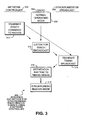
- FIG. 3 illustrates an embodiment 300 of a method for synchronizing beacon signals for networked radios.
- the embodiment 300 shows the operations of three different devices: a network controller 302, a radio 304, and the synchronization broadcast radio 306.
- the radio begins in normal operating mode in block 308.
- the network controller transmits a synchronization command in block 310 to the radio 304 and optionally to the synchronization radio 306.
- the radio 304 begins listening for the synchronization broadcast in block 312.
- the synchronization radio 306 transmits a timing broadcast in block 314, the radio 304 receives the broadcast and sets the beacon timing rhythm to the timing signal in block 316.
- the radio 304 begins synchronized beacon mode in block 318.
- Embodiment 300 illustrates one method whereby a controller 302 may initiate the synchronization sequence.
- the radio 304 Before the sequence, the radio 304 may be operating in a normal operating mode, which may not force beacon signals to be sent at specific intervals. In some cases, however, the radio 304 may be operating in synchronized beacon mode at the start of the sequence. At the end of the sequence, the radio 304 may operate in synchronized mode wherein the beacon signal is transmitted on the beacon rhythm.
- a radio system may not have a separate radio receiver that is used for receiving synchronization broadcasts.
- the radio may have to enter a mode as in block 312 where the radio ceases transmitting for a short period of time so that it will be able to receive the timing broadcast.
- FIG. 4 illustrates an embodiment 400 showing a sequence and method for synchronizing radio beacon signals when a synchronization receiver is present.
- the illustration shows the operations for a radio 402 and a synchronization broadcast 404.
- the radio 402 is comprised of a two way communication radio 406 and a synchronization receiver 408.
- the two way communication radio 406 may begin in normal operations mode in block 410.
- the synchronization receiver 408 may begin in receive mode 412.
- a timing broadcast is transmitted in block 414 which is received in block 416 by the synchronization receiver 408.
- the beacon rhythm is adjusted in block 418 to correspond to the timing of the synchronization broadcast.
- the two way radio 406 enters synchronized beacon mode in block 420.
- the beacon rhythm may be adjusted again in block 426.
- the two way radio 402 resumes synchronized beacon mode in block 428.
- the wireless access points 606, 608, and 610 may be mounted on utility poles for areas that have overhead utility lines. In areas with underground utilities, the wireless access points may be mounted on utility pedestals that are short stanchions connected to the underground cabling. The utility pedestals may also be used for making various connections with the underground cabling.
Landscapes
- Engineering & Computer Science (AREA)
- Computer Networks & Wireless Communication (AREA)
- Signal Processing (AREA)
- Computer Security & Cryptography (AREA)
- Radar, Positioning & Navigation (AREA)
- Remote Sensing (AREA)
- Mobile Radio Communication Systems (AREA)
Description
- The present invention relates to an IEEE 802.11 network, an IEEE 802.11 wireless access point, and to a method of transmitting beacon signals from an IEEE 802.11 wireless access point.
- Wireless communications networks are being widely deployed. In order to ensure subscriber coverage, a wireless network may have several radio transceivers positioned so that the coverage areas of the radios overlap. As radio coverage areas overlap, some interference and undesirable cross-communication between radios may occur. Such interference may decrease available bandwidth, which diminishes the number and quality of potential subscriber connections.
- Many wireless protocols have a feature whereby a device can sense if another device is using the specific frequency or band, and the first device will refrain from transmitting. In some protocols, the first device may retry the transmission at a later time, which may be a randomly generated time. Such a feature aims to minimize one device 'talking over' another device and preventing both device's transmissions from getting through. This collision detection feature is widely used in many different protocols, including standard wired Ethernet and wireless Ethernet-based protocols such as IEEE 802.11 wireless protocols.
- A distinct problem with such protocols is that the bandwidth is inherently underutilized and throughput for each device can be much less than optimal, especially when many devices are communicating on the network. When many devices attempt to communicate on the band simultaneously, the collision detection and avoidance procedures begin to occupy much of the communication bandwidth.
- It would therefore be advantageous to provide a system and method for providing improved use of the available bandwidth for communication networks having several radios.
-
WO 01/33744 -
US 2003/001776 discloses wireless network devices that can obtain their geographical location by triangulating with access points that have precise time information. In response to a location prompt, a wireless device can send a transmission to multiple access points that are within its range. The different times at which the transmission is received at different access points can be collected and forwarded to a server, which can compute the location of the wireless device using triangulation techniques. The access points can calibrate their own time bases from time services received from global position satellites. - The present invention provides an IEEE 802.11 network as set out in
claim 1. A broadcast signal is received substantially simultaneously by all of the radios and used to coordinate subsequent beacon signals. The broadcast signal may be a broadcast signal from a television broadcast, global positioning system broadcast, or any other broadcast designed to reach several radios substantially simultaneously. The radios may normally operate by detecting another transmission and refraining from transmitting until the transmission has ceased. However, while transmitting synchronized beacon signals the radios may broadcast simultaneously. Further features of the network are set out in claims 2 and 3. - The present invention also provides an IEEE 802.11 wireless access point as set out in claim 4. Further features are set out in claims 5 to 12.
- The present invention also provides a method of transmitting beacon signals as set out in claim 13. Further steps are set out in claims 14 to 20.
- In the drawings,
-
FIGURE 1 is a diagrammatic illustration of an embodiment showing a wireless network with overlapping coverage areas. -
FIGURE 2 is a diagrammatic illustration of an embodiment showing a wireless access point having multiple radios. -
FIGURE 3 is a flowchart illustration of an embodiment showing a method for synchronizing beacon signals for radios. -
FIGURE 4 is a flowchart illustration of an embodiment showing a method for synchronizing beacon signals for radios using a synchronization receiver. -
FIGURE 5 is a timeline illustration of an embodiment showing a sequence for synchronizing beacon signals. -
FIGURE 6 is a plan view illustration of a residential neighborhood having wireless access service. - Specific embodiments of the invention are described in detail below. The embodiments were selected to illustrate various features of the invention, but should not be considered to limit the invention to the embodiments described, as the invention is susceptible to various modifications and alternative forms.
- Throughout this specification, like reference numbers signify the same elements throughout the description of the figures.
- When elements are referred to as being "connected" or "coupled," the elements can be directly connected or coupled together or one or more intervening elements may also be present. In contrast, when elements are referred to as being "directly connected" or "directly coupled," there are no intervening elements present.
- The invention may be embodied as devices, systems, methods, and/or computer program products. Accordingly, some or all of the invention may be embodied in hardware and/or in software (including firmware, resident software, micro-code, state machines, gate arrays, etc.) Furthermore, the present invention may take the form of a computer program product on a computer-usable or computer-readable storage medium having computer-usable or computer-readable program code embodied in the medium for use by or in connection with an instruction execution system. In the context of this document, a computer-usable or computer-readable medium may be any medium that can contain, store, communicate, propagate, or transport the program for use by or in connection with the instruction execution system, apparatus, or device.
- The computer-usable or computer-readable medium may be, for example but not limited to, an electronic, magnetic, optical, electromagnetic, infrared, or semiconductor system, apparatus, device, or propagation medium. By way of example, and not limitation, computer readable media may comprise computer storage media and communication media.
- Computer storage media includes volatile and nonvolatile, removable and non-removable media implemented in any method or technology for storage of information such as computer readable instructions, data structures, program modules or other data. Computer storage media includes, but is not limited to, RAM, ROM, EEPROM, flash memory or other memory technology, CD-ROM, digital versatile disks (DVD) or other optical storage, magnetic cassettes, magnetic tape, magnetic disk storage or other magnetic storage devices, or any other medium which can be used to store the desired information and which can be accessed by an instruction execution system. Note that the computer-usable or computer-readable medium could be paper or another suitable medium upon which the program is printed, as the program can be electronically captured, via, for instance, optical scanning of the paper or other medium, then compiled, interpreted, of otherwise processed in a suitable manner, if necessary, and then stored in a computer memory.
- Communication media typically embodies computer readable instructions, data structures, program modules or other data in a modulated data signal such as a carrier wave or other transport mechanism and includes any information delivery media. The term "modulated data signal" means a signal that has one or more of its characteristics set or changed in such a manner as to encode information in the signal. By way of example, and not limitation, communication media includes wired media such as a wired network or direct-wired connection, and wireless media such as acoustic, RF, infrared and other wireless media. Combinations of the any of the above should also be included within the scope of computer readable media.
- When the invention is embodied in the general context of computer-executable instructions, the embodiment may comprise program modules, executed by one or more systems, computers, or other devices. Generally, program modules include routines, programs, objects, components, data structures, etc. that perform particular tasks or implement particular abstract data types. Typically, the functionality of the program modules may be combined or distributed as desired in various embodiments.
- Throughout this specification, the term "comprising" shall be synonymous with "including," "containing," or "characterized by," is inclusive or open-ended and does not exclude additional, unrecited elements or method steps. "Comprising" is a term of art which means that the named elements are essential, but other elements may be added and still form a construct within the scope of the statement. "Comprising" leaves open for the inclusion of unspecified ingredients even in major amounts.
-
Figure 1 illustrates anembodiment 100 showing a wireless network with overlapping coverage areas. Anetwork controller 102 is connected to anetwork backbone 104. Connected to thebackbone 104 areradio transceivers antenna 109 connected totransceiver 108.Transceiver 106 has acoverage area 114. Similarly,transceivers coverage areas coverage area 124. In thearea 124, radio transmissions from transceivers 106,108, and 112 all overlap. Abroadcast transmitter 126 andantenna 128 may be located anywhere that a signal broadcast fromantenna 128 may reach two or more of the radio transceivers. - In
embodiment 100, two or more of thetransceivers - Radio transceivers 106,108,110, and 112 may periodically transmit a beacon signal. Such a signal may identify the transceiver and provide information such that other devices in the area may begin communications. In many embodiments, the beacon signal may provide a unique identifier for the radio, as well as an identifier for the network and transmission parameters so that another device may successfully initiate communications.
- In many cases, radios that communicate with digitized or other forms of data communication, in a similar way as human operated audio radio communication, are able to listen on the communication band, determine that the band is quiet, then begin a transmission. If another device is transmitting, the radio is able to wait until the band is quiet before attempting another transmission. This technique prevents two radios from simultaneously transmitting and distorting each other's signals.
- Many standards have been developed for automated data transmission over wireless airwaves. Examples are cellular phone networks, wireless data standards such as IEEE 802.11, various spread spectrum and time division multiple access standards, and many others; however the present invention relates to IEEE 802.11.
- As more devices are attempting to communicate in a certain geographical area, the available bandwidth decreases. Especially after a certain number of devices is reached, the available bandwidth and data throughput decreases exponentially as more devices are added.
- One reason for the decrease in bandwidth is the communications overhead associated with each device. For example, fixed base stations may transmit a beacon signal on a periodic basis. In a typical prior art application, when one radio transmits a beacon signal, another radio within the area would be thereby forced to wait to transmit its beacon signal or any other signal. In an area where many radio coverage areas overlap, a significant portion of the bandwidth might become cluttered with the repeated transmission of beacon signals of the transceivers from overlapping coverage areas. This is because as each radio transmits its own beacon signal, all other devices typically refrain from transmitting.
- In the
embodiment 100, two or more of the transceivers may simultaneously transmit beacon signals. The coordinated transmission of beacon signals may eliminate much of the transmission overhead on a channel or frequency that is shared by all the transceivers. The coordination and synchronization of the beacon signals may be accomplished using many methods. In one method, abroadcast transmitter 126 may broadcast a signal that may be interpreted as having a timing component used to synchronize several of the radios at one time. - In some embodiments, every transceiver having overlapping coverage area with another transceiver may transmit synchronized beacon signals, whereas in other embodiments two or more transceivers may do so. In particularly busy areas, synchronized beacon signals are especially useful, since the bandwidth can be at a premium in congested areas.
- Some radio transmission schemes have a base and remote architecture. In such a scheme, the base stations have a defined transmission scheme that may include a repeated beacon signal. The remote devices in such a scheme may or may not transmit a beacon signal and may or may not be able to communicate directly from one remote device to another. Examples of such schemes include IEEE 802.11 and the various cellular phone architectures. In many cases, the base stations are connection points for other networks such as the Internet, cable television, or POTS phone system.
- In contrast, other schemes have a peer to peer architecture. In such a scheme, each device operates in the same manner as all the other devices in the area and any device is able to transmit to any other device in the area.
- One purpose of a beacon signal is to alert other devices in the area of a station's presence. In situations where a remote device is in the area of a base station, the remote device may be capable of listening for a base station's beacon signal, interpreting the signal, and establishing connections.
- For example, the device 122 is located within the transmission coverage areas of
radio transceivers area 124 is highlighted showing the overlapping coverage areas. If the beacon signals of thetransceivers transceiver - When the
transceivers transceiver 108 because the signal to noise ratio for the beacon signal fromtransceiver 108 may be greater than either of the simultaneous beacon signals fromtransceivers transceivers - Overlapping coverage areas are typical of many wireless networks where a full coverage is desired over a specific area. For example, a wireless data network may provide coverage in a large building, shopping mall, or airport using multiple radio transceivers with overlapping coverage areas. Similarly, a school campus or residential neighborhood may be blanketed by various wireless networks for data, voice, or other communications.
- For the purposes of this specification, the terms "radio," "radio transceiver," "wireless access point," "transceiver," and similar terms are used interchangeably. Similarly, the terms "backbone," "network," "network backbone," etc. are also used interchangeably.
- The radio transceivers have a mode which forces the beacon signals to be transmitted at the synchronized time, regardless if another device is transmitting.
- Many network architectures comprise a network backbone with several wireless transceivers attached to the backbone. For example, a wireless service provider may connect several wireless access points using digital subscriber line (DSL) connections to a central access point. In another example, a cable television and internet connection service may be provided through a hybrid fiber/coax (HFC) network with wireless subscriber connections mounted on utility poles or utility pedestals in a neighborhood.
- The
network backbone 104 may be any type of hardwired or wireless connection between the various transceivers. In some configurations, thebackbone 104 may be fiber optic cable, coaxial cable, twisted pair, or some other directly connected communication path. In other configurations, microwave communications or other radio frequency may be used to connect various portions of the network. In still other configurations, any combination of connection may be used. - The
controller 102 may be any type of device in communication with one or more of the transceivers. In some configurations, thecontroller 102 may be a centralized computer, hub, switch, gateway, headend, Cable Modem Termination System (CMTS), Digital Subscriber Line Access Multiplexer (DSLAM), or any other device that communicates along thebackbone 104. In some configurations, thecontroller 102 may provide connection between thebackbone 104 and the Internet, telephone network, or another outside network. - In some configurations, the
controller 102 may be a dedicated device that provides a synchronization function for the transceivers. In still other configurations, one of the transceivers may have a controller function enabled and function as both a transceiver as well as thecontroller 102. - The
controller 102 may provide various sorts of communications in order to set up and control the radio functions of the various transceivers. For example, thecontroller 102 may send commands to the radio transceivers to initiate sequences for synchronizing or for setting the mode from normal to synchronous beacon transmittal. In many cases, thecontroller 102 may additionally monitor the performance of the radio transmitters. -
Figure 2 illustrates anembodiment 200 of a wireless access point having two radio transceivers. Thewireless access point 202 containsradio transceivers Directional antennas transceivers synchronization receiver 224 hasantenna 226. Anetwork interface 210 connects the transceivers to thenetwork 214. Thedirectional antenna 207 has acoverage area 218. Similarly, thedirectional antenna 208 has acoverage area 220. The overlappingcoverage area 222 is the area where both antenna signals overlap. - The
wireless access point 202 may be a single device that is fixedly mounted in an area for wireless communications. For example, thewireless access point 202 may be mounted in an airport terminal, a coffee shop, a residential neighborhood, an office building, or any other area where it is desired to service the area with two or more radio transceivers. In many cases, a single radio transceiver may be overwhelmed by the communications, so it may be desirable to service the area by using multiple radios with directional antennas to cover specific sectors. In some cases, the sectors may overlap, while in other cases the sectors may not overlap. - In some configurations, the proximity of the
antennas - The beacon signals of the two
radio transceivers controller 210 using an incoming signal received by thesynchronization receiver 224. Thesynchronization receiver 224 may be any type of receiver that may receive a broadcast signal. For example, thereceiver 224 may be capable of receiving a standard shortwave time signal, a television broadcast, an AM or FM radio broadcast, satellite transmissions including global positioning system (GPS) signals, or any other type of broadcast on any frequency, standard, or protocol. - In some cases, the synchronization broadcast may be a specialized protocol on a specific frequency that is only intended for a synchronization operation. For example, when a network is installed, a portable transmitter may be set up in the area and used to broadcast synchronization signals that reach at least some of the wireless access points of the network.
- In other cases, the synchronization broadcast may be a transmission that has another purpose but could also be used for synchronizing the wireless access points on a network. For example, a GPS transmission or broadcast television signal has one or more time elements in a transmission that may be used to synchronize the beacon signals of the wireless access points. In such a case, the
synchronization receiver 224 may receive a signal such as a broadcast television signal and thecontroller 210 may decode the signal to extract a timing element that can be used to synchronize the beacon signals. Almost any broadcast signal with one or more known elements may be used for synchronizing the beacon signals. - In some cases, one of the
radio transceivers synchronization receiver 224. For example, theradio transceiver 206 may be capable of receiving the specific frequency or protocol of the broadcast synchronization signal. Theradio transceiver 206 may then receive the broadcast synchronization signal and relay the signal to thecontroller 210 for decoding or other processing. - Over the network, each wireless access point may receive the same signal and decode the signal in the same manner. As each wireless access point does so, it may establish an internal beacon rhythm and begin transmitting beacon signals on the beacon rhythm that may correspond with the beacon transmissions of other wireless access points.
- In many configurations, the
radio transceivers transceiver transceiver controller 210 or beacon heartbeat generators 212 or 216. - The network interface/
controller 210 may perform several functions, including transmitting communications between thenetwork 214 and theradio transceivers controller 210 may have a processor or state machine that is independent from theradio transceivers - The
embodiment 200 illustrates an example of a multiple radio transceiver system where the radio transceivers are located in very close proximity. Some configurations may have three or more radio transceivers. In some configurations, the system may have thewireless access point 202 located in one location, with thedirectional antennas wireless access point 202 may be located on one floor of a multistory building while the various directional antennas may be each located on a different floor of the building. The directional antennas in such an example may have a horizontal coverage area that covers one floor of the building. - The
embodiment 200 functions in a similar manner as theembodiment 100, with multiple radios having a synchronized beacon signal. In the case ofembodiment 200, the 'backbone' may be a communication path through thecontroller 210. - In a specific configuration of
embodiment 200, awireless access point 202 may be mounted in a single box with thedirectional antennas - The
network 214 may be any type of communication network. For example, thenetwork 214 may be a cable television network, a twisted pair digital subscriber line ('DSL') network, Ethernet, or other type of wired connection. In other examples, the network may be a wireless network designed to not interfere with theradio transmitters network 214. -
Figure 3 illustrates anembodiment 300 of a method for synchronizing beacon signals for networked radios. Theembodiment 300 shows the operations of three different devices: anetwork controller 302, aradio 304, and thesynchronization broadcast radio 306. The radio begins in normal operating mode inblock 308. The network controller transmits a synchronization command inblock 310 to theradio 304 and optionally to thesynchronization radio 306. Theradio 304 begins listening for the synchronization broadcast inblock 312. When thesynchronization radio 306 transmits a timing broadcast inblock 314, theradio 304 receives the broadcast and sets the beacon timing rhythm to the timing signal in block 316. Theradio 304 begins synchronized beacon mode inblock 318. -
Embodiment 300 illustrates one method whereby acontroller 302 may initiate the synchronization sequence. Before the sequence, theradio 304 may be operating in a normal operating mode, which may not force beacon signals to be sent at specific intervals. In some cases, however, theradio 304 may be operating in synchronized beacon mode at the start of the sequence. At the end of the sequence, theradio 304 may operate in synchronized mode wherein the beacon signal is transmitted on the beacon rhythm. - In some configurations, a radio system may not have a separate radio receiver that is used for receiving synchronization broadcasts. In such a configuration, the radio may have to enter a mode as in
block 312 where the radio ceases transmitting for a short period of time so that it will be able to receive the timing broadcast. - The
controller 302 may send the command ofblock 310 to both theradio 304 andsynchronization broadcast radio 306. When thesynchronization radio 306 is responsive to the command of thecontroller 302, the interval betweenblocks 312 and 316 may be quite short. If thesynchronization broadcast radio 306 is not capable of being initiated by thecontroller 302, the time period betweenblocks 312 and 316 may be quite length. - In an embodiment such as
embodiment 200, where two transceivers are present in one wireless interface, one of the two radios may be commanded to go into the listen mode ofblock 312 while the other radio continues normal operation. In anotherexample using embodiment 200, thesynchronization receiver 224 may be commanded to enter into the listen mode ofblock 312. -
Embodiment 300 allows anetwork controller 302 the ability to force synchronization to occur and to change the operating mode of the radio. In many cases, theradio 304 may first listen for any ongoing transmissions before it sends a message. In a normal operating mode, this attribute may be applied to beacon signals. While in such a mode, if several radios attempted to transmit a beacon signal, each radio may wait for the other radio to finish a beacon signal before transmitting its own. In order to gain the benefits of synchronizing beacons across several radios, each radio ignores the other transmissions for the period of time during the beacon transmission. Such a mode is shown inblock 318. -
Figure 4 illustrates anembodiment 400 showing a sequence and method for synchronizing radio beacon signals when a synchronization receiver is present. The illustration shows the operations for aradio 402 and asynchronization broadcast 404. Theradio 402 is comprised of a twoway communication radio 406 and asynchronization receiver 408. The twoway communication radio 406 may begin in normal operations mode inblock 410. Similarly, thesynchronization receiver 408 may begin in receivemode 412. When the synchronization broadcast transmission occurs, a timing broadcast is transmitted inblock 414 which is received inblock 416 by thesynchronization receiver 408. The beacon rhythm is adjusted inblock 418 to correspond to the timing of the synchronization broadcast. - The two
way radio 406 enters synchronized beacon mode inblock 420. When a second timing broadcast is transmitted inblock 422 and received inblock 424, the beacon rhythm may be adjusted again inblock 426. After adjusting, the twoway radio 402 resumes synchronized beacon mode inblock 428. -
Embodiment 400 illustrates an example of a repeated synchronization broadcast, which may be from a television broadcast, radio or satellite broadcast, including GPS broadcasts, or other type of repeated broadcast. The repeated broadcast may be on very specific and controlled intervals, or may be haphazard and infrequent, depending on the specific embodiment. In some cases, the frequency of the timing broadcast may be much more frequent than desired and many timing broadcasts may be ignored In some embodiments, thesynchronization broadcast 404 maybe a dedicated broadcast for the purpose of transmitting timing broadcasts. - In other embodiments, the synchronization receiver may be one of several receivers in a wireless access point such as
embodiment 200. In such an embodiment, thesynchronization receiver 408 may be one of theradio transceivers blocks -
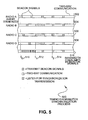
Figure 5 illustrates atiming diagram embodiment 500 for a synchronization process. The timing diagram illustrates events as they occur from left to right. Four radios are depicted inlines line 502, has already been synchronized and does not undergo the synchronization process. - At
time t0 510, all four radios are transmitting beacon signals at different times. In normal operation mode, where a radio waits to transmit while another radio is transmitting, much of the time betweent0 510 and t1 512 is consumed by beacon signals. At time t1 512, a command is issued to radios inlines - The
line 516 represents the total bandwidth consumed by beacon signals. The time betweent0 510 and t1 512 graphically illustrate how multiple beacon signals that are not synchronized may use a considerable amount of bandwidth when the radios are placed close enough apart that they may receive transmissions from each other. The time after t2 514 graphically illustrate much less bandwidth that is consumed by beacon signals. -
Figure 6 illustrates a plan view of anembodiment 600 showing wireless access points deployed in a residential area. Aroad 602 is shown withseveral houses 604.Wireless access points respective coverage areas network backbone 618 runs along themain road 602 and has ajunctaon 620 that connects thewireless access points -
Embodiment 600 is an application for wireless connectivity in a residential area. Thewireless access points homes 604, such as internet data connections, voice telephony, video services, and any other communication. The wireless acces points use the standardized radio communications protocol, defined by the IEEE 802.11 specification. - The
wireless access points - Each
wireless access point - The
network backbone 618 may be a coaxial cable, fiber optic, twisted pair, or other communications cable. In some configurations, thenetwork backbone 618 may be similar to a conventional cable television plant using DOCSIS or other communication protocols connected to a cable modem termination system ('CMTS'). - In other configurations, the
network backbone 618 may be twisted pair digital subscriber line ('DSL') lines that are connected using a digital subscriber line area manager ('DSLAM'). In still other configurations, the network may be an Ethernet or Ethernet-type network. - The
wireless access points embodiments
Claims (20)
- An IEEE 802.11 network (100; 200; 600) which utilises a collision detection and avoidance procedure, which network comprises:a plurality of wireless access points (106, 108, 110, 112; 202; 606, 608, 610), each of said plurality of wireless access points being adapted to establish at least one two-way data communication session, adapted to delay sending a transmission when another ongoing transmission is detected, and adapted to broadcast a beacon signal;wherein each of said plurality of wireless access points (106, 108, 110, 112; 202; 606, 608, 610) being adapted to receive a broadcast signal from an external network (126), such as a standard shortwave time signal, a television broadcast, an AM or FM radio broadcast, or satellite transmissions including global positioning system (GPS) signals, said broadcast signal having a timing component, and to transmit said beacon signal based on at least a portion of said broadcast signal so that (i) a plurality of beacon signals is transmitted substantially simultaneously by the plurality of wireless access points (106, 108, 110, 112; 202; 606, 608, 610), and (ii) each beacon signal is transmitted regardless of any other on-going transmissions from said plurality of wireless access points (106, 108, 110, 112; 202; 606, 608, 610).
- The network of claim 1 wherein said plurality of wireless access points (106, 108, 110, 112; 202; 606, 608, 610) are connected through a secondary communication path (104; 214; 618).
- The network of claim 2 wherein said secondary communication path (1-4; 214; 618) comprises at least one from a group composed of: a coaxial connection, a fiber optic connection, a twisted pair connection, a second wireless communications path, an Ethernet connection, a cable television distribution network and a digital subscriber line distribution network.
- A IEEE 802.11 wireless access point (106, 108, 110, 112; 202; 606, 608, 610) which utilises a collision detection and avoidance procedure, which wireless access point comprises:a transmitter; anda receiver;wherein said wireless access point is adapted to establish at least one two-way data communication session, adapted to delay sending a transmission when another ongoing transmission is detected, adapted to broadcast a beacon signal, adapted to receive a broadcast signal from an external network (126), such as a standard shortwave time signal, a television broadcast, an AM or FM radio broadcast, or satellite transmissions including global positioning system (GPS) signals, said broadcast signal having a timing component, and to transmit said beacon signal using a beacon rhythm derived from at least a portion of said broadcast signal whereby, in use, the wireless access point (106, 108, 110, 112; 202; 606, 608, 610) transmits beacon signals (i) substantially simultaneously with other wireless access points receiving the broadcast signal and (ii) each beacon signal is transmitted regardless of any other on-going transmissions from said other wireless access points (106, 108, 110, 112; 202; 606, 608, 610).
- The wireless access point of claim 4 wherein said at least one two-way communication session occurs within a first frequency band and said broadcast signal occurs within a second frequency band, said first frequency band and said second frequency band having at least some overlap.
- The wireless access point of claim 5 wherein said at least one two-way communication session occurs within a first frequency band and said broadcast signal occurs within a second frequency band, said first frequency band and said second frequency band having no overlap.
- The wireless access point of claim 4, 5 or 6, wherein said broadcast signal is one from a group composed of: a television broadcast signal, a GPS broadcast signal, and a dedicated synchronized beacon.
- The wireless access point of claim 4, 5, 6 or 7, further adapted to receive and not transmit during a beacon interval to receive beacon signals from one or more other radio transmitters.
- The wireless access point of claim 4, 5, 6, 7 or 8, further adapted to receive a synchronize command (310), wherein said synchronization command initiates a sequence comprising: disable transmission; receive at least one timing component of said broadcast signal; and enable two way communication.
- The wireless access point of claim 9, wherein said sequence further comprises using said timing component of said broadcast signal to determine the timing of said beacon signal.
- The wireless access point of any of claims 4 to 10 having a secondary communication path (104; 214; 618).
- The wireless access point of claim 11 wherein said secondary communication path (104; 214; 618) comprises at least one from a group composed of: a coaxial connection, a fiber optic connection, a twisted pair connection, a second wireless communications path, and an Ethernet connection, a cable television distribution network and a digital subscriber line distribution network.
- A method of transmitting beacon signals from an IEEE 802.11 wireless access point (106, 108, 110, 112; 202; 606, 608, 610) which utilises a collision detection and avoidance procedure, which method comprises:receiving a broadcast signal from an external network, such as a standard shortwave time signal, a television broadcast, an AM or FM radio broadcast, or satellite transmissions including global positioning system (GPS) signals, said broadcast signal having a timing component;determining a synchronized rhythm for transmission of a beacon signal based on said broadcast signal;establishing at least one two-way data communication session;delay sending a transmission when another on-going transmission is detected; andtransmitting said beacon signal in accordance with said synchronized rhythm regardless of any other on-going transmissions.
- The method of claim 13 wherein said at least one two-way communication session occurs within a first frequency band and said broadcast signal occurs within a second frequency band, said first frequency band and said second frequency band having at least some overlap.
- The method of claim 13 or 14 wherein said at least one two-way communication session occurs within a first frequency band and said broadcast signal occurs within a second frequency band, said first frequency band and said second frequency band having no overlap.
- The method of claim 13, 14 or 15, wherein said broadcast signal is one from a group composed of: a television broadcast signal, a GPS broadcast signal, and a dedicated synchronized beacon.
- The method of any of claims 13 to 16 further comprising receiving a synchronize command (310), said synchronize command comprising:disabling transmission;receiving at least one timing component of said broadcast signal; andenabling two way communication.
- The method of any of claims 13 to 17 further comprising:using said timing component of said broadcast signal to determine said synchronized rhythm.
- The method of any of claims 13 to 18 further comprising communication through a secondary communication path (104; 214; 618).
- The method of claim 19 wherein said secondary communication path comprises at least one from a group composed of: a coaxial connection, a fiber optic connection, a twisted pair connection, a second wireless communications path, an Ethernet connection, a cable television distribution network and a digital subscriber line distribution network.
Applications Claiming Priority (3)
| Application Number | Priority Date | Filing Date | Title |
|---|---|---|---|
| US67762505P | 2005-05-04 | 2005-05-04 | |
| US67762605P | 2005-05-04 | 2005-05-04 | |
| PCT/US2006/017222 WO2006119452A1 (en) | 2005-05-04 | 2006-05-04 | Externally sourced synchronized beacon |
Publications (3)
| Publication Number | Publication Date |
|---|---|
| EP1884072A1 EP1884072A1 (en) | 2008-02-06 |
| EP1884072A4 EP1884072A4 (en) | 2012-04-11 |
| EP1884072B1 true EP1884072B1 (en) | 2014-06-25 |
Family
ID=37308322
Family Applications (2)
| Application Number | Title | Priority Date | Filing Date |
|---|---|---|---|
| EP06759073.7A Expired - Lifetime EP1884072B1 (en) | 2005-05-04 | 2006-05-04 | Externally sourced synchronized beacon |
| EP06752247A Withdrawn EP1884071A4 (en) | 2005-05-04 | 2006-05-04 | Self synchronized beacon |
Family Applications After (1)
| Application Number | Title | Priority Date | Filing Date |
|---|---|---|---|
| EP06752247A Withdrawn EP1884071A4 (en) | 2005-05-04 | 2006-05-04 | Self synchronized beacon |
Country Status (4)
| Country | Link |
|---|---|
| US (2) | US20060251017A1 (en) |
| EP (2) | EP1884072B1 (en) |
| CA (2) | CA2607154A1 (en) |
| WO (2) | WO2006119452A1 (en) |
Families Citing this family (22)
| Publication number | Priority date | Publication date | Assignee | Title |
|---|---|---|---|---|
| US7433343B1 (en) | 2003-05-20 | 2008-10-07 | Mark Jeffrey Smith | Wireless system for communication |
| CN101371603B (en) | 2006-01-11 | 2013-10-23 | 高通股份有限公司 | Wireless Device Discovery in Wireless Peer-to-Peer Networks |
| US8811369B2 (en) | 2006-01-11 | 2014-08-19 | Qualcomm Incorporated | Methods and apparatus for supporting multiple communications modes of operation |
| JP4533342B2 (en) * | 2006-04-28 | 2010-09-01 | キヤノン株式会社 | COMMUNICATION DEVICE, ITS CONTROL METHOD, PROGRAM, AND STORAGE MEDIUM |
| CN101155036A (en) * | 2006-09-30 | 2008-04-02 | Thomson宽带研发(北京)有限公司 | Head end equipment of wired access network system |
| US20080181182A1 (en) * | 2007-01-12 | 2008-07-31 | Scott Carichner | Digital radio head system and method |
| US9521090B2 (en) * | 2007-06-04 | 2016-12-13 | Qualcomm Incorporated | Authorizing stations into a centrally managed network |
| FI20085423A0 (en) * | 2008-05-08 | 2008-05-08 | Nokia Siemens Networks Oy | Synchronization in a mobile communication system |
| US8595501B2 (en) | 2008-05-09 | 2013-11-26 | Qualcomm Incorporated | Network helper for authentication between a token and verifiers |
| US8588154B2 (en) * | 2009-01-30 | 2013-11-19 | Texas Instruments Incorporated | Mitigation of interference between wireless networks |
| US8774230B2 (en) | 2009-04-08 | 2014-07-08 | Qualcomm Incorporated | Conveying synchronization stratum information |
| US20110149798A1 (en) * | 2009-12-23 | 2011-06-23 | Carlos Cordeiro | Device, system and method of communicating using configured transmission directionality |
| US8520648B2 (en) * | 2010-06-14 | 2013-08-27 | Intel Corporation | Beacon transmission techniques in directional wireless networks |
| US10454768B2 (en) | 2013-11-15 | 2019-10-22 | F5 Networks, Inc. | Extending policy rulesets with scripting |
| EP3090599B1 (en) | 2013-12-30 | 2019-04-17 | Nokia Technologies Oy | Methods and apparatuses for proximity-based service |
| JP6212443B2 (en) * | 2014-07-07 | 2017-10-11 | 日本電信電話株式会社 | Wireless communication system and wireless communication method |
| EP3298708B1 (en) | 2015-05-22 | 2020-06-10 | CommScope Technologies LLC | Validation sub-system for telecommunication system |
| KR101988861B1 (en) * | 2016-03-02 | 2019-06-13 | 한국전자통신연구원 | Network join method and network device |
| US10326700B1 (en) * | 2016-03-29 | 2019-06-18 | F5 Networks, Inc. | Hash based per subscriber DNS based traffic classification |
| US10412663B2 (en) | 2017-03-21 | 2019-09-10 | Ademco Inc. | Systems and methods for detecting and avoiding radio interference in a wireless sensor network |
| US10257798B1 (en) * | 2018-05-18 | 2019-04-09 | OPNT Holding B.V. | Synchronizing clocks in a wireless system |
| US11265725B2 (en) | 2019-02-15 | 2022-03-01 | Ademco Inc. | Systems and methods for allocating wireless communication channels |
Family Cites Families (26)
| Publication number | Priority date | Publication date | Assignee | Title |
|---|---|---|---|---|
| SE518132C2 (en) | 1996-06-07 | 2002-08-27 | Ericsson Telefon Ab L M | Method and apparatus for synchronizing combined receivers and transmitters in a cellular system |
| US5940765A (en) * | 1996-08-30 | 1999-08-17 | Telefonaktiebolaget Lm Ericsson | Radio communications systems and methods for jittered beacon transmission |
| US6351463B1 (en) * | 1998-04-06 | 2002-02-26 | Avaya Technology Corp. | Method and apparatus for transmitting a synchronization beacon in a wireless communication network |
| US6961555B1 (en) | 1998-09-11 | 2005-11-01 | L.V. Partners, L.P. | System and apparatus for connecting a wireless device to a remote location on a network |
| US6594273B1 (en) | 1999-07-09 | 2003-07-15 | Telecommunications Research Laboratories | Self-configuring radio network |
| KR100726743B1 (en) * | 1999-11-03 | 2007-06-11 | 퀄컴 인코포레이티드 | Synchronous Pilot Reference Transmission for Wireless Communication Systems |
| JP3673149B2 (en) * | 2000-07-11 | 2005-07-20 | クラリオン株式会社 | High speed roaming method for wireless LAN |
| US7126937B2 (en) * | 2000-12-26 | 2006-10-24 | Bluesocket, Inc. | Methods and systems for clock synchronization across wireless networks |
| US6618005B2 (en) * | 2001-06-29 | 2003-09-09 | Intel Corporation | Determining wireless device locations |
| US7689225B2 (en) * | 2002-01-28 | 2010-03-30 | Ntt Docomo, Inc. | Method and apparatus for dormant mode support with paging |
| JP4158703B2 (en) | 2002-03-04 | 2008-10-01 | ソニー株式会社 | Wireless communication system, wireless communication apparatus, wireless communication method, and computer program |
| JP3849551B2 (en) * | 2002-03-05 | 2006-11-22 | ソニー株式会社 | Wireless communication system, wireless communication apparatus and method, and computer program |
| US7313127B2 (en) | 2002-04-19 | 2007-12-25 | General Electric Company | Method and apparatus for synchronizing a radio telemetry system by way of transmitted-reference, delay-hopped ultra-wideband pilot signal |
| US7499460B2 (en) * | 2002-04-26 | 2009-03-03 | Samsung Electronics Co., Ltd. | Integrated WI-FI and wireless public network and method of operation |
| JP4419956B2 (en) * | 2003-01-07 | 2010-02-24 | ソニー株式会社 | Wireless communication apparatus, wireless communication system, and wireless communication method |
| CN101662816B (en) * | 2003-02-03 | 2014-03-05 | 索尼株式会社 | Radio communication system, radio communication device, radio communication method, and computer program |
| US7764706B2 (en) | 2003-03-20 | 2010-07-27 | University Of Rochester | Time reservation using adaptive control for energy efficiency |
| US7231221B2 (en) | 2003-09-12 | 2007-06-12 | Telefonaktiebolaget L M Ericsson (Publ) | Channel access methods and apparatus in low-power wireless communication systems |
| US7457271B2 (en) | 2003-09-19 | 2008-11-25 | Marvell International Ltd. | Wireless local area network ad-hoc mode for reducing power consumption |
| US7412246B2 (en) * | 2003-10-06 | 2008-08-12 | Symbol Technologies, Inc. | Method and system for improved wlan location |
| US7796526B2 (en) * | 2003-10-31 | 2010-09-14 | Acterna | Versatile communication network test apparatus and methods |
| US20050124294A1 (en) | 2003-11-17 | 2005-06-09 | Conextant Systems, Inc. | Wireless access point simultaneously supporting basic service sets on multiple channels |
| US7047009B2 (en) * | 2003-12-05 | 2006-05-16 | Flarion Technologies, Inc. | Base station based methods and apparatus for supporting break before make handoffs in a multi-carrier system |
| JP4054341B2 (en) | 2004-05-17 | 2008-02-27 | 三星電子株式会社 | Fast handover method optimized for IEEE 802.11 network |
| US20060089099A1 (en) * | 2004-10-26 | 2006-04-27 | Buchwald Gregory J | Method and apparatus for allowing communication units to utilize non-licensed spectrum |
| US7019691B1 (en) | 2005-04-07 | 2006-03-28 | Pctel,Maryland, Inc. | Method and apparatus for beacon discovery in a spread spectrum cellular radio communication system |
-
2006
- 2006-05-04 CA CA002607154A patent/CA2607154A1/en not_active Abandoned
- 2006-05-04 US US11/417,732 patent/US20060251017A1/en not_active Abandoned
- 2006-05-04 CA CA002607163A patent/CA2607163A1/en not_active Abandoned
- 2006-05-04 US US11/417,686 patent/US8315573B2/en not_active Expired - Fee Related
- 2006-05-04 WO PCT/US2006/017222 patent/WO2006119452A1/en not_active Ceased
- 2006-05-04 EP EP06759073.7A patent/EP1884072B1/en not_active Expired - Lifetime
- 2006-05-04 EP EP06752247A patent/EP1884071A4/en not_active Withdrawn
- 2006-05-04 WO PCT/US2006/017223 patent/WO2006119453A1/en not_active Ceased
Also Published As
| Publication number | Publication date |
|---|---|
| WO2006119453A1 (en) | 2006-11-09 |
| US20060252378A1 (en) | 2006-11-09 |
| US20060251017A1 (en) | 2006-11-09 |
| EP1884072A1 (en) | 2008-02-06 |
| US8315573B2 (en) | 2012-11-20 |
| CA2607154A1 (en) | 2006-11-09 |
| EP1884071A4 (en) | 2012-11-21 |
| EP1884071A1 (en) | 2008-02-06 |
| CA2607163A1 (en) | 2006-11-09 |
| EP1884072A4 (en) | 2012-04-11 |
| WO2006119452A1 (en) | 2006-11-09 |
Similar Documents
| Publication | Publication Date | Title |
|---|---|---|
| US8315573B2 (en) | Externally sourced synchronized beacon | |
| JP7289436B2 (en) | Beaconing in short wavelength wireless networks | |
| US6850502B1 (en) | Join process method for admitting a node to a wireless mesh network | |
| CN101390429B (en) | Apparatus and method for controlling channel switching in wireless networks | |
| CA2058737C (en) | Rf repeater arrangement with improved frequency reuse for wireless telephones | |
| JP5059029B2 (en) | Method and system for adjusting the bandwidth by extending the range of a wireless network | |
| US6230015B1 (en) | Picking up of mobile stations from a direct mode channel | |
| EP0999656B1 (en) | Cellular mobile communication system comprising multicast channel | |
| US8483741B1 (en) | Mitigation of inter-network interference to enable channel reuse | |
| US20100195590A1 (en) | Method and apparatus for radio spectrum sensing or monitoring | |
| US8169996B2 (en) | Synchronized beacon for network having multiple radios | |
| US7822074B2 (en) | Synchronization between uncoordinated time division duplex communication networks | |
| KR20090026293A (en) | Wireless repeater with master / slave configuration | |
| JP2001526509A (en) | Base station synchronization method and cellular system | |
| JP4651852B2 (en) | Channel selection method and subscriber station in wireless communication system | |
| EP3536011A1 (en) | Adjusting attribute of remote unit based on information regarding interfering device to cause subscriber unit to connect to and/or camp on remote unit rather than interfering device | |
| CN110022603B (en) | Method and device for synchronization between base stations | |
| JPH11136735A (en) | Wireless communication system | |
| US11917682B2 (en) | Wireless LAN system and interference control method | |
| KR101590409B1 (en) | System and method for preventing interference in beacon signal superposition area, and apparatus applied thereto | |
| JPH08116569A (en) | Radio transmission system,central radio station and radio station | |
| CN120547587A (en) | Data transmission method, communication device, storage medium, and program product | |
| JPH02295243A (en) | Co-channel signal transmission system |
Legal Events
| Date | Code | Title | Description |
|---|---|---|---|
| PUAI | Public reference made under article 153(3) epc to a published international application that has entered the european phase |
Free format text: ORIGINAL CODE: 0009012 |
|
| 17P | Request for examination filed |
Effective date: 20071130 |
|
| AK | Designated contracting states |
Kind code of ref document: A1 Designated state(s): AT BE BG CH CY CZ DE DK EE ES FI FR GB GR HU IE IS IT LI LT LU LV MC NL PL PT RO SE SI SK TR |
|
| DAX | Request for extension of the european patent (deleted) | ||
| A4 | Supplementary search report drawn up and despatched |
Effective date: 20120314 |
|
| RIC1 | Information provided on ipc code assigned before grant |
Ipc: H04W 84/12 20090101ALN20120308BHEP Ipc: H04W 56/00 20090101AFI20120308BHEP Ipc: H04B 7/26 20060101ALN20120308BHEP Ipc: H04W 48/12 20090101ALN20120308BHEP |
|
| 17Q | First examination report despatched |
Effective date: 20121211 |
|
| REG | Reference to a national code |
Ref country code: DE Ref legal event code: R079 Ref document number: 602006042046 Country of ref document: DE Free format text: PREVIOUS MAIN CLASS: H04L0012280000 Ipc: H04W0056000000 |
|
| RIC1 | Information provided on ipc code assigned before grant |
Ipc: H04W 48/10 20090101ALI20131025BHEP Ipc: H04W 56/00 20090101AFI20131025BHEP Ipc: H04W 48/12 20090101ALN20131025BHEP Ipc: H04W 36/16 20090101ALN20131025BHEP Ipc: H04W 84/18 20090101ALN20131025BHEP Ipc: H04W 84/12 20090101ALN20131025BHEP Ipc: H04B 7/26 20060101ALI20131025BHEP Ipc: H04W 74/00 20090101ALN20131025BHEP |
|
| GRAP | Despatch of communication of intention to grant a patent |
Free format text: ORIGINAL CODE: EPIDOSNIGR1 |
|
| INTG | Intention to grant announced |
Effective date: 20131206 |
|
| GRAS | Grant fee paid |
Free format text: ORIGINAL CODE: EPIDOSNIGR3 |
|
| GRAA | (expected) grant |
Free format text: ORIGINAL CODE: 0009210 |
|
| AK | Designated contracting states |
Kind code of ref document: B1 Designated state(s): AT BE BG CH CY CZ DE DK EE ES FI FR GB GR HU IE IS IT LI LT LU LV MC NL PL PT RO SE SI SK TR |
|
| REG | Reference to a national code |
Ref country code: GB Ref legal event code: FG4D |
|
| REG | Reference to a national code |
Ref country code: CH Ref legal event code: EP |
|
| REG | Reference to a national code |
Ref country code: AT Ref legal event code: REF Ref document number: 675337 Country of ref document: AT Kind code of ref document: T Effective date: 20140715 |
|
| REG | Reference to a national code |
Ref country code: IE Ref legal event code: FG4D |
|
| REG | Reference to a national code |
Ref country code: DE Ref legal event code: R096 Ref document number: 602006042046 Country of ref document: DE Effective date: 20140807 |
|
| PG25 | Lapsed in a contracting state [announced via postgrant information from national office to epo] |
Ref country code: FI Free format text: LAPSE BECAUSE OF FAILURE TO SUBMIT A TRANSLATION OF THE DESCRIPTION OR TO PAY THE FEE WITHIN THE PRESCRIBED TIME-LIMIT Effective date: 20140625 Ref country code: GR Free format text: LAPSE BECAUSE OF FAILURE TO SUBMIT A TRANSLATION OF THE DESCRIPTION OR TO PAY THE FEE WITHIN THE PRESCRIBED TIME-LIMIT Effective date: 20140926 Ref country code: CY Free format text: LAPSE BECAUSE OF FAILURE TO SUBMIT A TRANSLATION OF THE DESCRIPTION OR TO PAY THE FEE WITHIN THE PRESCRIBED TIME-LIMIT Effective date: 20140625 Ref country code: LT Free format text: LAPSE BECAUSE OF FAILURE TO SUBMIT A TRANSLATION OF THE DESCRIPTION OR TO PAY THE FEE WITHIN THE PRESCRIBED TIME-LIMIT Effective date: 20140625 |
|
| REG | Reference to a national code |
Ref country code: AT Ref legal event code: MK05 Ref document number: 675337 Country of ref document: AT Kind code of ref document: T Effective date: 20140625 |
|
| REG | Reference to a national code |
Ref country code: NL Ref legal event code: VDEP Effective date: 20140625 |
|
| REG | Reference to a national code |
Ref country code: LT Ref legal event code: MG4D |
|
| PG25 | Lapsed in a contracting state [announced via postgrant information from national office to epo] |
Ref country code: LV Free format text: LAPSE BECAUSE OF FAILURE TO SUBMIT A TRANSLATION OF THE DESCRIPTION OR TO PAY THE FEE WITHIN THE PRESCRIBED TIME-LIMIT Effective date: 20140625 Ref country code: SE Free format text: LAPSE BECAUSE OF FAILURE TO SUBMIT A TRANSLATION OF THE DESCRIPTION OR TO PAY THE FEE WITHIN THE PRESCRIBED TIME-LIMIT Effective date: 20140625 |
|
| PG25 | Lapsed in a contracting state [announced via postgrant information from national office to epo] |
Ref country code: EE Free format text: LAPSE BECAUSE OF FAILURE TO SUBMIT A TRANSLATION OF THE DESCRIPTION OR TO PAY THE FEE WITHIN THE PRESCRIBED TIME-LIMIT Effective date: 20140625 Ref country code: CZ Free format text: LAPSE BECAUSE OF FAILURE TO SUBMIT A TRANSLATION OF THE DESCRIPTION OR TO PAY THE FEE WITHIN THE PRESCRIBED TIME-LIMIT Effective date: 20140625 Ref country code: PT Free format text: LAPSE BECAUSE OF FAILURE TO SUBMIT A TRANSLATION OF THE DESCRIPTION OR TO PAY THE FEE WITHIN THE PRESCRIBED TIME-LIMIT Effective date: 20141027 Ref country code: ES Free format text: LAPSE BECAUSE OF FAILURE TO SUBMIT A TRANSLATION OF THE DESCRIPTION OR TO PAY THE FEE WITHIN THE PRESCRIBED TIME-LIMIT Effective date: 20140625 Ref country code: RO Free format text: LAPSE BECAUSE OF FAILURE TO SUBMIT A TRANSLATION OF THE DESCRIPTION OR TO PAY THE FEE WITHIN THE PRESCRIBED TIME-LIMIT Effective date: 20140625 Ref country code: SK Free format text: LAPSE BECAUSE OF FAILURE TO SUBMIT A TRANSLATION OF THE DESCRIPTION OR TO PAY THE FEE WITHIN THE PRESCRIBED TIME-LIMIT Effective date: 20140625 |
|
| PG25 | Lapsed in a contracting state [announced via postgrant information from national office to epo] |
Ref country code: IS Free format text: LAPSE BECAUSE OF FAILURE TO SUBMIT A TRANSLATION OF THE DESCRIPTION OR TO PAY THE FEE WITHIN THE PRESCRIBED TIME-LIMIT Effective date: 20141025 Ref country code: PL Free format text: LAPSE BECAUSE OF FAILURE TO SUBMIT A TRANSLATION OF THE DESCRIPTION OR TO PAY THE FEE WITHIN THE PRESCRIBED TIME-LIMIT Effective date: 20140625 Ref country code: AT Free format text: LAPSE BECAUSE OF FAILURE TO SUBMIT A TRANSLATION OF THE DESCRIPTION OR TO PAY THE FEE WITHIN THE PRESCRIBED TIME-LIMIT Effective date: 20140625 Ref country code: NL Free format text: LAPSE BECAUSE OF FAILURE TO SUBMIT A TRANSLATION OF THE DESCRIPTION OR TO PAY THE FEE WITHIN THE PRESCRIBED TIME-LIMIT Effective date: 20140625 |
|
| REG | Reference to a national code |
Ref country code: DE Ref legal event code: R097 Ref document number: 602006042046 Country of ref document: DE |
|
| PG25 | Lapsed in a contracting state [announced via postgrant information from national office to epo] |
Ref country code: DK Free format text: LAPSE BECAUSE OF FAILURE TO SUBMIT A TRANSLATION OF THE DESCRIPTION OR TO PAY THE FEE WITHIN THE PRESCRIBED TIME-LIMIT Effective date: 20140625 Ref country code: IT Free format text: LAPSE BECAUSE OF FAILURE TO SUBMIT A TRANSLATION OF THE DESCRIPTION OR TO PAY THE FEE WITHIN THE PRESCRIBED TIME-LIMIT Effective date: 20140625 |
|
| PLBE | No opposition filed within time limit |
Free format text: ORIGINAL CODE: 0009261 |
|
| STAA | Information on the status of an ep patent application or granted ep patent |
Free format text: STATUS: NO OPPOSITION FILED WITHIN TIME LIMIT |
|
| 26N | No opposition filed |
Effective date: 20150326 |
|
| PG25 | Lapsed in a contracting state [announced via postgrant information from national office to epo] |
Ref country code: BE Free format text: LAPSE BECAUSE OF FAILURE TO SUBMIT A TRANSLATION OF THE DESCRIPTION OR TO PAY THE FEE WITHIN THE PRESCRIBED TIME-LIMIT Effective date: 20140625 |
|
| REG | Reference to a national code |
Ref country code: DE Ref legal event code: R097 Ref document number: 602006042046 Country of ref document: DE Effective date: 20150326 |
|
| PG25 | Lapsed in a contracting state [announced via postgrant information from national office to epo] |
Ref country code: SI Free format text: LAPSE BECAUSE OF FAILURE TO SUBMIT A TRANSLATION OF THE DESCRIPTION OR TO PAY THE FEE WITHIN THE PRESCRIBED TIME-LIMIT Effective date: 20140625 |
|
| REG | Reference to a national code |
Ref country code: DE Ref legal event code: R119 Ref document number: 602006042046 Country of ref document: DE |
|
| REG | Reference to a national code |
Ref country code: CH Ref legal event code: PL |
|
| GBPC | Gb: european patent ceased through non-payment of renewal fee |
Effective date: 20150504 |
|
| PG25 | Lapsed in a contracting state [announced via postgrant information from national office to epo] |
Ref country code: LU Free format text: LAPSE BECAUSE OF FAILURE TO SUBMIT A TRANSLATION OF THE DESCRIPTION OR TO PAY THE FEE WITHIN THE PRESCRIBED TIME-LIMIT Effective date: 20150504 Ref country code: MC Free format text: LAPSE BECAUSE OF FAILURE TO SUBMIT A TRANSLATION OF THE DESCRIPTION OR TO PAY THE FEE WITHIN THE PRESCRIBED TIME-LIMIT Effective date: 20140625 Ref country code: LI Free format text: LAPSE BECAUSE OF NON-PAYMENT OF DUE FEES Effective date: 20150531 Ref country code: CH Free format text: LAPSE BECAUSE OF NON-PAYMENT OF DUE FEES Effective date: 20150531 |
|
| REG | Reference to a national code |
Ref country code: IE Ref legal event code: MM4A |
|
| REG | Reference to a national code |
Ref country code: FR Ref legal event code: ST Effective date: 20160129 |
|
| PG25 | Lapsed in a contracting state [announced via postgrant information from national office to epo] |
Ref country code: IE Free format text: LAPSE BECAUSE OF NON-PAYMENT OF DUE FEES Effective date: 20150504 Ref country code: DE Free format text: LAPSE BECAUSE OF NON-PAYMENT OF DUE FEES Effective date: 20151201 Ref country code: GB Free format text: LAPSE BECAUSE OF NON-PAYMENT OF DUE FEES Effective date: 20150504 |
|
| PG25 | Lapsed in a contracting state [announced via postgrant information from national office to epo] |
Ref country code: FR Free format text: LAPSE BECAUSE OF NON-PAYMENT OF DUE FEES Effective date: 20150601 |
|
| PG25 | Lapsed in a contracting state [announced via postgrant information from national office to epo] |
Ref country code: BG Free format text: LAPSE BECAUSE OF FAILURE TO SUBMIT A TRANSLATION OF THE DESCRIPTION OR TO PAY THE FEE WITHIN THE PRESCRIBED TIME-LIMIT Effective date: 20140625 Ref country code: HU Free format text: LAPSE BECAUSE OF FAILURE TO SUBMIT A TRANSLATION OF THE DESCRIPTION OR TO PAY THE FEE WITHIN THE PRESCRIBED TIME-LIMIT; INVALID AB INITIO Effective date: 20060504 |
|
| PG25 | Lapsed in a contracting state [announced via postgrant information from national office to epo] |
Ref country code: TR Free format text: LAPSE BECAUSE OF FAILURE TO SUBMIT A TRANSLATION OF THE DESCRIPTION OR TO PAY THE FEE WITHIN THE PRESCRIBED TIME-LIMIT Effective date: 20140625 |