EP1883854B1 - Variable contrast, wide viewing angle liquid crystal light attenuation filter - Google Patents
Variable contrast, wide viewing angle liquid crystal light attenuation filter Download PDFInfo
- Publication number
- EP1883854B1 EP1883854B1 EP06753533A EP06753533A EP1883854B1 EP 1883854 B1 EP1883854 B1 EP 1883854B1 EP 06753533 A EP06753533 A EP 06753533A EP 06753533 A EP06753533 A EP 06753533A EP 1883854 B1 EP1883854 B1 EP 1883854B1
- Authority
- EP
- European Patent Office
- Prior art keywords
- light
- cell
- lcd1
- lcd2
- negative
- Prior art date
- Legal status (The legal status is an assumption and is not a legal conclusion. Google has not performed a legal analysis and makes no representation as to the accuracy of the status listed.)
- Ceased
Links
- 239000004973 liquid crystal related substance Substances 0.000 title claims description 97
- 208000028485 lattice corneal dystrophy type I Diseases 0.000 claims description 88
- 101000894525 Homo sapiens Transforming growth factor-beta-induced protein ig-h3 Proteins 0.000 claims description 87
- 102100021398 Transforming growth factor-beta-induced protein ig-h3 Human genes 0.000 claims description 87
- 230000003287 optical effect Effects 0.000 claims description 59
- 230000005540 biological transmission Effects 0.000 claims description 40
- 239000002052 molecular layer Substances 0.000 claims description 30
- 239000011521 glass Substances 0.000 claims description 26
- 230000000295 complement effect Effects 0.000 claims description 17
- 230000001154 acute effect Effects 0.000 claims description 12
- 239000002019 doping agent Substances 0.000 claims description 5
- 239000010408 film Substances 0.000 description 53
- 230000001681 protective effect Effects 0.000 description 19
- 230000009977 dual effect Effects 0.000 description 13
- 238000003466 welding Methods 0.000 description 12
- 230000033228 biological regulation Effects 0.000 description 9
- 238000005516 engineering process Methods 0.000 description 8
- 230000008901 benefit Effects 0.000 description 6
- 238000010276 construction Methods 0.000 description 5
- 230000000694 effects Effects 0.000 description 5
- 238000005457 optimization Methods 0.000 description 5
- 238000005094 computer simulation Methods 0.000 description 4
- 238000010586 diagram Methods 0.000 description 4
- 238000004519 manufacturing process Methods 0.000 description 4
- 239000000758 substrate Substances 0.000 description 4
- 239000004988 Nematic liquid crystal Substances 0.000 description 3
- 239000004642 Polyimide Substances 0.000 description 3
- 238000010521 absorption reaction Methods 0.000 description 3
- 230000000875 corresponding effect Effects 0.000 description 3
- 230000005684 electric field Effects 0.000 description 3
- 230000001747 exhibiting effect Effects 0.000 description 3
- 230000004048 modification Effects 0.000 description 3
- 238000012986 modification Methods 0.000 description 3
- 229920001721 polyimide Polymers 0.000 description 3
- 239000000047 product Substances 0.000 description 3
- 239000006059 cover glass Substances 0.000 description 2
- 238000005520 cutting process Methods 0.000 description 2
- 238000005259 measurement Methods 0.000 description 2
- QLNWXBAGRTUKKI-UHFFFAOYSA-N metacetamol Chemical compound CC(=O)NC1=CC=CC(O)=C1 QLNWXBAGRTUKKI-UHFFFAOYSA-N 0.000 description 2
- 238000000034 method Methods 0.000 description 2
- 230000010287 polarization Effects 0.000 description 2
- 229920000642 polymer Polymers 0.000 description 2
- 230000004044 response Effects 0.000 description 2
- 230000003595 spectral effect Effects 0.000 description 2
- 238000001228 spectrum Methods 0.000 description 2
- 101100208473 Neurospora crassa (strain ATCC 24698 / 74-OR23-1A / CBS 708.71 / DSM 1257 / FGSC 987) lcm-2 gene Proteins 0.000 description 1
- 230000006978 adaptation Effects 0.000 description 1
- 238000004458 analytical method Methods 0.000 description 1
- 238000000149 argon plasma sintering Methods 0.000 description 1
- 230000000712 assembly Effects 0.000 description 1
- 238000000429 assembly Methods 0.000 description 1
- 230000000903 blocking effect Effects 0.000 description 1
- 230000008859 change Effects 0.000 description 1
- 230000008094 contradictory effect Effects 0.000 description 1
- 230000002596 correlated effect Effects 0.000 description 1
- 238000013461 design Methods 0.000 description 1
- 238000009826 distribution Methods 0.000 description 1
- 238000011156 evaluation Methods 0.000 description 1
- 230000002349 favourable effect Effects 0.000 description 1
- 238000001914 filtration Methods 0.000 description 1
- 239000012467 final product Substances 0.000 description 1
- 239000005329 float glass Substances 0.000 description 1
- 239000011888 foil Substances 0.000 description 1
- 230000006872 improvement Effects 0.000 description 1
- 238000002329 infrared spectrum Methods 0.000 description 1
- 230000003993 interaction Effects 0.000 description 1
- 238000012538 light obscuration Methods 0.000 description 1
- 239000000203 mixture Substances 0.000 description 1
- 230000002093 peripheral effect Effects 0.000 description 1
- 230000008569 process Effects 0.000 description 1
- 230000005855 radiation Effects 0.000 description 1
- 239000000565 sealant Substances 0.000 description 1
- 230000035945 sensitivity Effects 0.000 description 1
- 239000005361 soda-lime glass Substances 0.000 description 1
- 125000006850 spacer group Chemical group 0.000 description 1
- 239000010409 thin film Substances 0.000 description 1
- 238000002211 ultraviolet spectrum Methods 0.000 description 1
- 238000001429 visible spectrum Methods 0.000 description 1
- 230000000007 visual effect Effects 0.000 description 1
Images



Classifications
-
- G—PHYSICS
- G02—OPTICS
- G02F—OPTICAL DEVICES OR ARRANGEMENTS FOR THE CONTROL OF LIGHT BY MODIFICATION OF THE OPTICAL PROPERTIES OF THE MEDIA OF THE ELEMENTS INVOLVED THEREIN; NON-LINEAR OPTICS; FREQUENCY-CHANGING OF LIGHT; OPTICAL LOGIC ELEMENTS; OPTICAL ANALOGUE/DIGITAL CONVERTERS
- G02F1/00—Devices or arrangements for the control of the intensity, colour, phase, polarisation or direction of light arriving from an independent light source, e.g. switching, gating or modulating; Non-linear optics
- G02F1/01—Devices or arrangements for the control of the intensity, colour, phase, polarisation or direction of light arriving from an independent light source, e.g. switching, gating or modulating; Non-linear optics for the control of the intensity, phase, polarisation or colour
- G02F1/13—Devices or arrangements for the control of the intensity, colour, phase, polarisation or direction of light arriving from an independent light source, e.g. switching, gating or modulating; Non-linear optics for the control of the intensity, phase, polarisation or colour based on liquid crystals, e.g. single liquid crystal display cells
- G02F1/137—Devices or arrangements for the control of the intensity, colour, phase, polarisation or direction of light arriving from an independent light source, e.g. switching, gating or modulating; Non-linear optics for the control of the intensity, phase, polarisation or colour based on liquid crystals, e.g. single liquid crystal display cells characterised by the electro-optical or magneto-optical effect, e.g. field-induced phase transition, orientation effect, guest-host interaction or dynamic scattering
- G02F1/139—Devices or arrangements for the control of the intensity, colour, phase, polarisation or direction of light arriving from an independent light source, e.g. switching, gating or modulating; Non-linear optics for the control of the intensity, phase, polarisation or colour based on liquid crystals, e.g. single liquid crystal display cells characterised by the electro-optical or magneto-optical effect, e.g. field-induced phase transition, orientation effect, guest-host interaction or dynamic scattering based on orientation effects in which the liquid crystal remains transparent
- G02F1/1396—Devices or arrangements for the control of the intensity, colour, phase, polarisation or direction of light arriving from an independent light source, e.g. switching, gating or modulating; Non-linear optics for the control of the intensity, phase, polarisation or colour based on liquid crystals, e.g. single liquid crystal display cells characterised by the electro-optical or magneto-optical effect, e.g. field-induced phase transition, orientation effect, guest-host interaction or dynamic scattering based on orientation effects in which the liquid crystal remains transparent the liquid crystal being selectively controlled between a twisted state and a non-twisted state, e.g. TN-LC cell
- G02F1/1397—Devices or arrangements for the control of the intensity, colour, phase, polarisation or direction of light arriving from an independent light source, e.g. switching, gating or modulating; Non-linear optics for the control of the intensity, phase, polarisation or colour based on liquid crystals, e.g. single liquid crystal display cells characterised by the electro-optical or magneto-optical effect, e.g. field-induced phase transition, orientation effect, guest-host interaction or dynamic scattering based on orientation effects in which the liquid crystal remains transparent the liquid crystal being selectively controlled between a twisted state and a non-twisted state, e.g. TN-LC cell the twist being substantially higher than 90°, e.g. STN-, SBE-, OMI-LC cells
-
- G—PHYSICS
- G02—OPTICS
- G02F—OPTICAL DEVICES OR ARRANGEMENTS FOR THE CONTROL OF LIGHT BY MODIFICATION OF THE OPTICAL PROPERTIES OF THE MEDIA OF THE ELEMENTS INVOLVED THEREIN; NON-LINEAR OPTICS; FREQUENCY-CHANGING OF LIGHT; OPTICAL LOGIC ELEMENTS; OPTICAL ANALOGUE/DIGITAL CONVERTERS
- G02F1/00—Devices or arrangements for the control of the intensity, colour, phase, polarisation or direction of light arriving from an independent light source, e.g. switching, gating or modulating; Non-linear optics
- G02F1/01—Devices or arrangements for the control of the intensity, colour, phase, polarisation or direction of light arriving from an independent light source, e.g. switching, gating or modulating; Non-linear optics for the control of the intensity, phase, polarisation or colour
- G02F1/13—Devices or arrangements for the control of the intensity, colour, phase, polarisation or direction of light arriving from an independent light source, e.g. switching, gating or modulating; Non-linear optics for the control of the intensity, phase, polarisation or colour based on liquid crystals, e.g. single liquid crystal display cells
- G02F1/133—Constructional arrangements; Operation of liquid crystal cells; Circuit arrangements
- G02F1/1333—Constructional arrangements; Manufacturing methods
- G02F1/1347—Arrangement of liquid crystal layers or cells in which the final condition of one light beam is achieved by the addition of the effects of two or more layers or cells
- G02F1/13471—Arrangement of liquid crystal layers or cells in which the final condition of one light beam is achieved by the addition of the effects of two or more layers or cells in which all the liquid crystal cells or layers remain transparent, e.g. FLC, ECB, DAP, HAN, TN, STN, SBE-LC cells
Definitions
- the invention relates to high contrast, wide viewing angle Liquid Crystal (LC) light switching filters optimized for specific requirements in particularly encountered in eye protection applications (recommendation and requirements of EN 379,).
- LC Liquid Crystal
- the technical field of the present invention is the field of LCD light-switching optical filters allowing for high, electrically continuously variable light attenuation (up to ⁇ 100.000) optimized / symmetrized for the light incidence along the normal to the LCD plane and requiring that a light blocking be effective even, when light travels through the light-switching filters within a limited cone of angles off the normal incidence direction (- see for example international safety and quality regulation EN 379 for personal protection optical devices).
- Such light-switching optical filters are used in particular for applications in human eye protection (for example: welding protective filters), in stereovision and specialized optical devices. Since the LCD light filters are typically autonomous, battery powered devices, the performances such as the accuracy of the light attenuation in the optically closed (eye protective) state as well as the overall power consumption of the driving electronics strongly depend on the light transmission/voltage characteristics of the LCD light filters and its optimization is essential for achieving the state-of -the-art performances.
- active light filters based on LCD light shutters are very specialized LCD products typically used for eye protection and stereovision devices. As such they are subject to noticeably different technical requirements, as found with typical LCD display applications.
- a point to be emphasized here is, that due to the voltage limitations, that exist for picture elements in the multiplex addressed LCD screens of lap-top computers and TV, as well as the overall user requirements for these display panels, the developed technical solutions did not lead to the desired performance and cost target for a shutter device, that has to be used for example in the personal protection devices.
- the drive voltage can be two to four times that of a LCD for a lap-top computer, and it is much more critical, that very high light attenuations are reached and the off-normal axis light extinction properties of the device are excellent.
- the automatic LCD active light filters in their "optically closed” state usually operate in a "dark scale” regime (light attenuation > 10), quite often even as two state devices in optically fully open and highly “optically closed state” (- the major issue of the presented patent application). They typically require very high light attenuation, which can be realized only with more than one (2 or even 3) LCD light shutters joint in the final protective device. Having more than one LCD light shutter in a device, significantly affects the overall problem of the angular dependence of the light attenuation as well as its symmetry around the normal to the LCD plane.
- the authors also teach that a positive-birefringent layer having its optic axis oriented in the plane of the LCD light filter is used to reduce the residual retardation of the LC cell in the optically closed state in order to reduce the driving voltage necessary for achieving high light attenuation.
- Such an additional element is necessary in order to compensate for the residual birefringence of the Pi-cell in the optically closed state so that the driving voltage necessary for achieving the required high light attenuation is reduced to acceptable value.
- the authors also propose the specific relative orientation of the LCD cells to improve the overall angular dependence of the LCD light switching filter and even introduce the use of additional in-plane (LCD) quarter-wave plate to increase this possibility.
- a head-mounted see-through visual display which enables an outside image and an electronic image to be selectively observed by making a liquid crystal shutter transparent or opaque.
- display light from a two-dimensional display device is first transmitted by a half-mirror, and the transmitted light is reflected by a concave mirror.
- a negative or positive type TN or STN liquid crystal shutter is disposed in front of the half-mirror.
- a liquid crystal shutter comprising a liquid crystal device including a nematic liquid crystal sealed in between a first transparent substrate and a second transparent substrate on whose inner surface are formed respective transparent electrodes.
- the liquid crystal device is having a twisted angle to or greater than 180°.
- a pair of polarizing plates are sandwiched between the first transparent substrate and the second transparent substrate.
- the polarizing films have respective absorption axes which are substantially orthogonal to each other, the absorption axes of the polarizing films being angled within a range of +/- 40° to +/-50° relative to the direction in which the intermediate liquid crystal molecules are orientated.
- the liquid crystal shutter disclosed is having a fast response.
- WO 2004/102265 A1 discloses a wide viewing angle LCD light switching element with two crossed polarizers, one electrically controlled optical birefringent LC cell including a layer of highly twisted liquid crystal enclosed between two boundary glass plates and a negative-birefringent compensating layer built-in between the boundary glass plates and either one of the crossed polarizers.
- the layer of highly twisted liquid crystal is formed with a twist angle of at least nearly 180° and the crossed polarizers are oriented with respect to a liquid crystal surface alignment direction determined by the alignment layers so that only a single mode of light propagation is selected.
- the object of the present invention is to provide a LCD light-switching optical filter allowing for very high, electrically controlled, continuously variable light attenuation (up to ⁇ 100.000) optimized / symmetrized for the light incidence along the normal to the LCD plane.
- the proposed light switching filter comprises two electrically controlled optical birefringent elements - LC-cells LCD1, LCD2, two mutually crossed pairs of polarizing films (polarizer P, analyzer A) P 1 , A 1 and P 2 , A 2 , adjacent to the light input and output sides of the said LC-cells LCD1, LCD2, as shown for example on the Fig.
- each of the said LC-cells LCD1, LCD2 using a thin layer of liquid crystal molecules oriented in a highly twisted configuration enclosed between two boundary glass plates 1a a , 1a b , the said plates 1a a , 1a b being on the inner side covered by transparent electrodes 1b a , 1b b and alignment layers 1c a , 1c b , as shown for example on the Fig. 1 .
- the whole assembly optionally has additional negative-birefringent compensating layers R1 , R2 protective cover glass C and "photopic" filter PF reflecting harmful IR an UV light.
- the proposed "HTLS concept” assuming twisting of the LC-molecular ordering through the LC-cells LCD1 and LCD2 well beyond 90°, optionally using a dual "complementary" LC-cell filter structure and rotating the crossed polarizers away from the symmetry axes between the LC-molecular alignment directions at the LC-cell boundaries, provides an additional optical symmetry essential for the low angular dependence of the light attenuation.
- Optimization of the molecular twist angle, chiral dopant concentration and the angle between the polarizers and the symmetry axes of the LC alignment directions at the LC-cell boundaries further results in the "ideal" electrooptic response and in the expansion of the viewing angle, which remains preserved through a broad range of driving voltages.
- the LC-cell technical parameters as obtained according to the above described HTLS concept are noticeably different from the standard technical parameters used with standard STN LCD information panels.
- the latter are with STN LCDs optimized for multiplex driving in the high-slope regime of operation ( Fig. 3 ). Therefore the polarizing films have to be aligned along the symmetry axes of the LC-molecular alignment and the highest technically possible LC-molecular twist angles ⁇ are used (typically ⁇ 240°) as opposed to the HTLS principle, where lower twist angles ⁇ are significantly more favorable (typically 225°).
- Chiral doping of the LC with STN LCDs has to be carefully adjusted (fixed) to avoid the stripe instabilities and backflow effects, while this is not the case with the HTLS principle since the LC-cells operate at higher driving voltages (low-slope regime LS) and the chiral doping can be used for optimizing the light transmission/voltage characteristics of the LCD light-switching filter.
- the objective of the present invention is a concept of the LCD light-switching optical filter allowing for very high, electrically controlled, continuously variable light attenuation (up to ⁇ 100.000) optimized / symmetrized for the light incidence along the normal to the LCD plane.
- the new LCD light-switching optical filter has to exhibit very low light attenuation dependence for the oblique incidence of light within a limited cone of angles off the normal incidence direction (preferably ⁇ 15° - see international safety and quality regulation EN 379 for personal protection optical devices).
- High contrast and wide viewing angle in the optically closed state of the LCD light switching filters are achieved using a multilayer laminate comprising two electrically controlled optical birefringent elements - LC-cells LCD1, LCD2, two mutually crossed pairs of polarizing films P 1 , A 1 and P 2 , A 2 , adjacent to the light input and output sides of the said LC-cells LCD1, LCD2, each of the said LC-cells LCD1, LCD2 using a thin layer of liquid crystal molecules oriented in a highly twisted configuration (twist angles ⁇ from 120 to 240 degrees) enclosed between two boundary glass plates 1a a , 1a b , the said plates 1a a , 1a b being on the inner side covered by transparent electrodes 1b a , 1b b and alignment layers 1c a , 1c b , as shown on the Fig.
- the LC-cells LCD1 respectively LCD2 have additional negative-birefringent compensating layers R1, R2 laminated between them and the adjacent polarizing films P 1 , A 1 respectively P 2 , A 2 in order to further improve the overall optical properties.
- the block diagram of such LCD light switching filter is shown on the Figs. 9a , b.
- the highly-twisted LC molecular structure has important advantages for optical light shutter applications (HTLS) as required for LCD light switching filters both from the light transmission/driving voltage characteristics (paragraph #1) as well as overall optical (paragraph #2) performances point of view:
- the electro-optically active LCD light shutters cannot fulfill the above requirements only by themselves, as they are based on the use of polarizing films, which are developed to be efficient more or less only in the visible light spectrum - an additional protection against invisible UV and IR light is necessary. Since one is dealing with relatively high intensity light sources, this additional protection is preferably achieved by a filter, exhibiting selective reflection rather than absorption in the IR and UV spectral range, while being transparent in the visible spectral range, simulating more or less the eye sensitivity curve - "- photopic filter". Such an additional passive selective "mirror" furthermore guarantees permanent eye protection irrespective of the potential malfunctioning of the active LCD light filtering in the visible spectrum.
- the present state-of-the-art LCD light-switching filters allowing for variable protective shade are typically made as multilayer laminates of at least two electrically controlled optical birefringent elements - LC-cells, adequate number of mutually crossed pairs of polarizing films, adjacent to the light input and output sides of the said LC-cells and on the outer sides having protective cover glass plates, one of which having on its inner side a thin film "photopic" filter layer reflecting harmful IR an UV light (see the block diagram on the Fig. 9a or b ).
- the electrically controlled optical birefringent elements - LC-cells ( Fig. 1 ), which represent the key subcomponets of the LCD light switching filter, are made according to the standard STN LCD production process, using soda-lime glass as the LC-cell boundary plates 1a a , 1a b .
- the boundary glass plates 1a a , 1a b are covered with the transparent ITO electrodes 1b a , 1b b , preferably exhibiting a surface resistivity typically 50 Ohm/square.
- the said electrodes are further covered with typically 50 nm thick, low residual DC voltage (RDC) polyimide like SE 4792 (Nissan).
- the latter is further filled in vacuum with liquid crystal, preferably a specialized STN mixture like MLC-14000-100 (Merck).
- liquid crystal preferably a specialized STN mixture like MLC-14000-100 (Merck).
- the said liquid crystal is doped with 0.95% of the chiral dopant like S811.
- the fill hole is further sealed with UV curable sealant like NOA 61 (Norland).
- Both LC-cells LCD1 and LCD2 are manufactured in the same way except that LC-alignment directions 2r a , 2r b in the second LC-cell LCD2 are swapped for 90 degrees with respect to the alignment directions 1r a , 1r b of the first LC-cell LCD1 (-complementary structure).
- a high contrast polarizing film P 1 like LLC2-5618 (Sanritz) is laminated on the light input boundary glass 1a a of the LC-cell LCD1 so that its light-transmitting axis is aligned to be 6 degrees away from perpendicular direction to the symmetry axis S 1 1 of the LC-alignment directions of the said LC-cell LCD1.
- the same procedure is repeated for the polarizing film P 2 on the light input side of the second LC-cell LCD2 its light-transmitting axis being again aligned to be 6 degrees away from perpendicular direction to the symmetry axis S 1 2 of the LC-alignment directions of the said second LC-cell LCD2 (see Fig. 9a ).
- the negative-birefringent layer R1 having its optic axis perpendicular to the LC-cell LCD1 plane, is subsequently laminated on the light output side of the boundary glass plate 1a b of the LC-cell LCD1.
- the same process is repeated for the negative-birefringent layer R2 laminated on the second LC-cell LCD2.
- the same kind of polarizing films (LLC2-5618) are further laminated as the light output polarizing films A1 and A2 on the light output sides of the negative-birefringent layers R1 respectively R2.
- the two assemblies of LC-cells comprising LC-cells LCD1 and LCD2 with the corresponding polarizing films P 1 , A 1 respectively P 2 , A 2 and negative birefringent layers R1 respectively R2 are subsequently laminated together so that the light output polarizing film A 1 of the first assembly and the light input polarizing film P 2 of the second assembly are aligned parallel to each other.
- the whole laminate is covered with the protective glass plates C, the protective glass plate on the light input side being on the side facing the polarizing film P 1 covered with a multilayer photopic filter PF selectively reflecting the light in the IR and UV spectrum while transmitting the visible light.
- the resulting effective positive birefringence (200nm) with the optic axis perpendicular to the LCD light switching filter plane together with the in-plane effective residual retardation of the boundary layers d a , d b of the LC-molecular layer allow for very efficient overall angular compensation of the light attenuation of the LCD light switching filter in the optically closed state.
- FIG. 9b A typical example of a possible modification is shown on the Fig. 9b , where the polarization (P1, P2) of the incoming light is parallel to the symmetry axes S 1 1 respectively S 1 2 of the LC-molecular orientation in the LC-cells LCD1, respectively LCD2 and not perpendicular, as assumed in the EXAMPLE.
- Such a change of the relative polarization direction with respect to the symmetry axes S 1 1 respectively S 1 2 of the LC-molecular orientation results in the "shift" of the retardation layers R1, respectively R2 from the light output sides of the LC-cells LCD1 respectively LCD2,to the light input positions.
Landscapes
- Physics & Mathematics (AREA)
- Nonlinear Science (AREA)
- Chemical & Material Sciences (AREA)
- Crystallography & Structural Chemistry (AREA)
- General Physics & Mathematics (AREA)
- Optics & Photonics (AREA)
- Mathematical Physics (AREA)
- Liquid Crystal (AREA)
Description
- The invention relates to high contrast, wide viewing angle Liquid Crystal (LC) light switching filters optimized for specific requirements in particularly encountered in eye protection applications (recommendation and requirements of EN 379,...).
- The technical field of the present invention is the field of LCD light-switching optical filters allowing for high, electrically continuously variable light attenuation (up to ≥ 100.000) optimized / symmetrized for the light incidence along the normal to the LCD plane and requiring that a light blocking be effective even, when light travels through the light-switching filters within a limited cone of angles off the normal incidence direction (- see for example international safety and quality regulation EN 379 for personal protection optical devices).
- Such light-switching optical filters are used in particular for applications in human eye protection (for example: welding protective filters), in stereovision and specialized optical devices. Since the LCD light filters are typically autonomous, battery powered devices, the performances such as the accuracy of the light attenuation in the optically closed (eye protective) state as well as the overall power consumption of the driving electronics strongly depend on the light transmission/voltage characteristics of the LCD light filters and its optimization is essential for achieving the state-of -the-art performances.
- The above requirements are significantly different from the angular dependence issue in the technical field of LCD screens for laptop computers, monitors and TV, where rather moderate light contrasts are required and the symmetry of the light attenuation around the normal to the LCD plane is not so important (best viewing angle), while the limit of the viewing angle is typically determined as the angle of the gray scale inversion.
- The fundamentals of the above mentioned problems are well understood, because the origin of these problems is very similar to the well-known "viewing angle" problem found in L iquid C rystal D isplays (LCDs) in general. Because of the very large impact of the viewing angle problem, found in liquid crystal displays (LCDs) of laptop computers and TV, worldwide interest in this problem has led to a number of solutions.
- It has to be emphasized that active light filters, based on LCD light shutters are very specialized LCD products typically used for eye protection and stereovision devices. As such they are subject to noticeably different technical requirements, as found with typical LCD display applications. A point to be emphasized here is, that due to the voltage limitations, that exist for picture elements in the multiplex addressed LCD screens of lap-top computers and TV, as well as the overall user requirements for these display panels, the developed technical solutions did not lead to the desired performance and cost target for a shutter device, that has to be used for example in the personal protection devices. In the case of a shutter device for personal eye-protection applications (e.g.: welding glasses,...), the drive voltage can be two to four times that of a LCD for a lap-top computer, and it is much more critical, that very high light attenuations are reached and the off-normal axis light extinction properties of the device are excellent.
- The automatic LCD active light filters in their "optically closed" state (- eye protection!) usually operate in a "dark scale" regime (light attenuation > 10), quite often even as two state devices in optically fully open and highly "optically closed state" (- the major issue of the presented patent application). They typically require very high light attenuation, which can be realized only with more than one (2 or even 3) LCD light shutters joint in the final protective device. Having more than one LCD light shutter in a device, significantly affects the overall problem of the angular dependence of the light attenuation as well as its symmetry around the normal to the LCD plane.
- The most typical examples of stacked LCDs are found with automatic LCD light switching filters for personal protection applications in welding, where light attenuation exceeding 100.000 is required.
So Harsch et al (US 4,039,254 ) andReisacher at all (DE 3721751 ) teach that stacking at least two standard Twist Nematic (TN) LCD (90° twist) light shutters in tandem provides the light attenuation, as required for eye protection in welding applications. None of them however discloses the advantage of the choice of the "complementary TN LCD light shutters" (complementary viewing angles), which can improve and symmetrize the overall viewing angle of the LCD welding filter. - Significantly more detailed analysis is provided in the patents of A. Hornell (
WO 97/15254 WO97/15255 WO95/29428 Young et all (US5940155 ). The authors also teach that a positive-birefringent layer having its optic axis oriented in the plane of the LCD light filter is used to reduce the residual retardation of the LC cell in the optically closed state in order to reduce the driving voltage necessary for achieving high light attenuation. - The use of a different LCD technology (Pi-cell), exhibiting a significantly better angular symmetry than the above mentioned "TN and LTN solutions" is introduced for automatic LCD light filters by
Fergason et al (US 5,515,186 ,) from OSD Envision. They teach that stacking at least two Pi-cells in a tandem provides adequate light attenuation. With the difference from the above-mentioned Hornell's patents (LTN technology) the polarizers are not aligned along the bisectrices of the LC alignment directions on the boundaries of the LCD cells. The authors also claim the use of positive-birefringent layers, having their optic axis oriented in the plane of the LCD light filter and perpendicularly to the LC-molecular alignment. Such an additional element is necessary in order to compensate for the residual birefringence of the Pi-cell in the optically closed state so that the driving voltage necessary for achieving the required high light attenuation is reduced to acceptable value. The authors also propose the specific relative orientation of the LCD cells to improve the overall angular dependence of the LCD light switching filter and even introduce the use of additional in-plane (LCD) quarter-wave plate to increase this possibility. - None of the above mentioned patents discloses the use of a negative-birefringent layer with the optic axis oriented along the normal to the LCD light filter plane (negative-birefringent c-plate) to correct for the positive birefringence of the homeotropically aligned LC molecules in the "optically closed" state of the LCD light switching filter - the major source of the annoying high angular dependence of the light attenuation of the LCD light filters. They also do not mention the use of "complementary constructed LC-cells" stacked in a tandem in order to further reduce the angular dependence of the LCD light filters. Finally none of the above mentioned technical solutions mentions nor allows a "specific optimization" (other than standard LCD panel solutions) of the LCD cell parameters (like LC-molecular orientation twist angles, relative orientation of the polarizing films with respect to the LC-molecular alignment,...) to get the required value and slope of the light transmission/voltage characteristics. Since the LCD light filters are typically autonomous, battery powered devices, the performances of the driving electronics are rather limited by the possible choice of batteries. The accuracy of the adjustment of the light attenuation and especially the overall power consumption therefore strongly depend on the light transmission/voltage characteristics of the LCD light filters.
- From
US 5,572,343 a head-mounted see-through visual display which enables an outside image and an electronic image to be selectively observed by making a liquid crystal shutter transparent or opaque. To eliminate the problem that during the observation of the electronic image the outside image is undesirably seen through the peripheral region of the electronic image, display light from a two-dimensional display device is first transmitted by a half-mirror, and the transmitted light is reflected by a concave mirror. To prevent the outside light from entering the eye through the half-mirror during the observation of the electronic image, a negative or positive type TN or STN liquid crystal shutter is disposed in front of the half-mirror. When the electronic image is to be viewed, the shutter is made opaque, whereas whem the outside image is to be viewed, the shutter is made transparent. - From
US 2001/0035925 A1 a liquid crystal shutter is known, comprising a liquid crystal device including a nematic liquid crystal sealed in between a first transparent substrate and a second transparent substrate on whose inner surface are formed respective transparent electrodes. The liquid crystal device is having a twisted angle to or greater than 180°. A pair of polarizing plates are sandwiched between the first transparent substrate and the second transparent substrate. The polarizing films have respective absorption axes which are substantially orthogonal to each other, the absorption axes of the polarizing films being angled within a range of +/- 40° to +/-50° relative to the direction in which the intermediate liquid crystal molecules are orientated. The liquid crystal shutter disclosed is having a fast response. -
WO 2004/102265 A1 discloses a wide viewing angle LCD light switching element with two crossed polarizers, one electrically controlled optical birefringent LC cell including a layer of highly twisted liquid crystal enclosed between two boundary glass plates and a negative-birefringent compensating layer built-in between the boundary glass plates and either one of the crossed polarizers. The layer of highly twisted liquid crystal is formed with a twist angle of at least nearly 180° and the crossed polarizers are oriented with respect to a liquid crystal surface alignment direction determined by the alignment layers so that only a single mode of light propagation is selected. - The object of the present invention is to provide a LCD light-switching optical filter allowing for very high, electrically controlled, continuously variable light attenuation (up to ≥ 100.000) optimized / symmetrized for the light incidence along the normal to the LCD plane.
- High contrast and wide viewing angle in the optically closed state (eye protective state) are achieved with the LCD light switching filter according to
claim 1. Advantageous embodiments of this filter are subject matter of the subclaims. - The proposed light switching filter comprises two electrically controlled optical birefringent elements - LC-cells LCD1, LCD2, two mutually crossed pairs of polarizing films (polarizer P, analyzer A) P1, A1 and P2, A2, adjacent to the light input and output sides of the said LC-cells LCD1, LCD2, as shown for example on the
Fig. 9a ,b , each of the said LC-cells LCD1, LCD2 using a thin layer of liquid crystal molecules oriented in a highly twisted configuration enclosed between two boundary glass plates 1a a, 1a b, the said plates 1a a, 1a b being on the inner side covered bytransparent electrodes Fig. 1 . The whole assembly optionally has additional negative-birefringent compensating layers R1, R2 protective cover glass C and "photopic" filter PF reflecting harmful IR an UV light. - Key features of the proposed invention and/or its advantageous embodiments are the highly twisted Liquid Crystal (LC) molecular orientation of the LCD light shutter, its operation in the "low-slope regime LS" of the light transmission/driving voltage characteristics (
Fig. 3 ) and the complementary dual LC-cell configuration of the LCD light switching filter (Fig. 9a ,b ). The resulting overall symmetry of the proposed LCD light switching filter allows for very high, continuously electrically variable optical attenuation, as well as efficient angular compensation using just simple, low cost negative-birefringent c-plate retarders. The proposed technical solutions according to the invention noticeably improve the overall optical performances of the LCD light-switching filters, which significantly exceed the highest requirements of the international safety standards (i.e.: EN 379,...) for eye protection devices: - a. High level of light attenuation (up to ≥100.000) in the "optically closed" state of the filter
- b. Precision continuous electrical adjustment of the light attenuation of the filter
- c. Optimization for the light incidence along the normal to the LCD light filter plane,
- d. Compensation for the angular dependence of light attenuation,
- e. High switching speed.
- The above features represent the most essential performance requirements for the automatic LCD light switching filters for eye protection applications. According to the invention they are very efficiently realized using LCD light shutters based on the standard STN technology optimized according to the following concept - Highly Twisted Light Shutter - HTLS:
- Ad a . Since the required high level of light attenuation can be achieved only by using two LCD light shutters in a tandem, relatively low light attenuations (45 - 350) are required for each of them to cover the entire protective range, as required by international standards like
EN 379. So relatively low light attenuation typically achieved with STN LCDs is not a problem. Moreover, higher driving electric fields, necessary for achieving the same light attenuation as the standard TN LCD light shutters, as well as the overall HTLS operational concept, result in noticeably better homeotropic alignment of the LC molecules in the optically closed state than with the conventional TN or LTN technologies (seeFig. 7 ). This property can be very efficiently used to help compensating for the angular dependence of the light attenuation (see Ad d for details). - Ad b. The most contradicting requirement seems to be the precision continuous adjustment of the light attenuation, as the light transmission/voltage characteristic of the STN LCD is generally believed to be a lot steeper than with TN or LTN technologies. This is however true only for the relatively low light attenuation, while for the higher attenuation (≥45) the slope of the light transmission / driving voltage V characteristics levels off (see
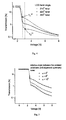
Fig. 3 ) and is typically few times smaller because of the unbalanced residual retardation of the thin boundary LC molecular layers da , db , where the surface interactions compete with the driving electric field (seeFig. 1 ). The limiting minimum driving voltage amplitude VLS for the "low-slope regime" (V≥ VLS; seeFig. 3 ) depends on the twist angle Φ and so does the overall slope of the light transmission / driving voltage characteristics (Fig. 4 ). This property of the STN LCDs has never been considered to be important, as the said STN LCDs were developed with only high information content LCD panels in mind, where the driving voltage V is varied in the high-slope regime of the light transmission / driving voltage characteristics (Fig. 3 ) from the switching threshold voltage V th to a limiting voltage VLS for the onset of the low-slope regime (Vth ≤ V ≤ VLS). With highly twisted LCD light shutters according to the invention (HTLS), used in LCD light switching filters for personal protection applications the LC molecular twist angle Φ is not the only technical parameter affecting the light transmission/voltage characteristic. Besides the LC molecular twist angle Φ the said characteristics is also controlled by the chiral doping (seeFig. 6 ) of the liquid crystal (da +db +e) and/or by the relative angle α between the crossed polarizers and the LC-alignment (Fig. 5 ; see also Ad c.). The light attenuation required for the LCD light switching filters for personal protection applications is typically (e.g. welding) in the range from - 4000 to ≥ 100.000. With variable protective shade LCD light switching filters the light transmission in the optically closed (protection) state is therefore adjusted in the "dark scale" (higher light attenuation) rather than in the "gray scale" regime typical for the computer or TV terminals. In view of this one can optimize one, two or all three technical parameters specified above (Figs. 4, 5 and6 ) to achieve that the light transmission of the LCD light switching filter is adjustable only within the higher driving voltage, "low-slope" regime (V ≥ VLS), as shown in theFig. 3 . Furthermore the said three technical parameters allow for adjusting the LCD light switching filter performances to optimally fit the available maximum driving voltage V amplitude span of the particular electronic driving circuitry, which is typically strongly limited by the batteries used to power the said circuitry. - Ad c . The light attenuation of highly twisted LCD light shutters (HTLS) in the optically closed state can exhibit reasonably good symmetry around the normal to the LCD plane provided that the crossed polarizers are aligned along the symmetry axes (for example for the first LC cell: S1 1, S 2 1) of the LC alignment directions (for example for the first LC cell: 1ra , 1rb ) on the boundary plates of the LCD light shutter (
Fig. 2 ). This symmetry is further improved by using "complementary" structure of both LCD light shutters in the LCD light switching filter:- LC alignment rotated for 90°
- the output polarizer A1 of the first LCD light shutter LCD1 - parallel to the input polarizer P2 of the second LCD light shutter LCD2
- all other parameters - identical.
Such a dual "complementary" LCD construction of the filter makes the constraint for the crossed polarizers P1 , A1 adjacent to the first LC-cell LCD1 and for the crossed polarizers P2, A2 adjacent to the second LC-cell LCD2 being aligned along the symmetry axes S1 1 and S2 1 of the LC alignment directions of the first LCD1 respectively along the symmetry axes S1 2 and S2 2 the second LC-cell LCD2 less strict, as the angular dependencies of the light transmission of said two complementary LC-cells compensate each other. The use of a tandem of complementary LC-cells therefore allows for some rotation of the crossed pairs of polarizers P1, A1 and P2, A2 for a relative angle α away from the said ideal orientations (Fig. 2 ). The light transmission/driving voltage characteristics noticeably depends on the relative angle α between the crossed polarizers P1, A1 respectively P2, A2 and the symmetry axes S1 1, S2 1 respectively S1 2, S2 2 (seeFig. 5 ). Therefore the said angle α can be further used to optimize the overall absolute value of the light transmission characteristics and broaden the interval LS for the "dark scale" operation of the LCD light switching filters as well as to broaden the overall viewing angle of the LCD light switching filter in the optically closed state. - Ad d. The dual "complementary" HTLS construction significantly simplifies the problem of angular compensation of the light attenuation in the optically closed state of the LCD light switching filter. Besides the superior angular independence of the light attenuation as compared to standard TN or LTN solutions, which results from the high symmetry of the LC-molecular orientation in the HTLS construction, the viewing angle can be further expanded by optimizing the relative angle α between the crossed polarizers P1, A1 and P2, A2 and the LC alignment 1ra, 1rb and 2ra, 2rb (see also the Detailed description). Finally as already mentioned (Ad a) HTLS concept exhibits increased homeotropic alignment (see
Fig. 7 ), which can be very efficiently compensated by the addition of only a simple negative-birefringent c-plate layers R1 respectively R2 built-in between the two LC-cells LCD1 respectively LCD2 and the adjacent crossed polarizers P1, A1 respectively P2, A2 (claim 8). A combination of all these effects results in a very appropriate overall angular compensation of the light attenuation, which is in complete compliance with the highest demands of the international standards likeEN 379. The excellent angular dependence (seeFig. 8 ) for the optimized value of the additional negative-birefringent c-plate layers R1 respectively R2 results from the fact that the relative positioning of the said negative-birefringent c-plate layers R1 respectively R2 according to this patent application (claims 9, 10, 11), allows not only for compensating the angular dependence of the homeotropically oriented central part e of the LC molecular layer (seeFig. 1 ) with both LC-cells LCD1 and LCD2 but also for a great deal of the angular dependence of the crossed polarizers P1, A1 and P2, A2 adjacent to the LC-cells LCD1 and LCD2. The said additional compensation effect can be achieved, if the effective "negative-retardation" of the said negative-birefringent c-plate layers R1 respectively R2 is deliberately chosen to be smaller than the effective "positive-retardation" of the homeotropically oriented central LC-molecular layer e (seeFig. 1 ). The resulting positive-birefringence having the optic axis aligned along the normal to the LC-cell ("c-plate"), if combined with the residual in-plane ("a-plate") positive-birefringence of the boundary LC-molecular layers da, db can result in a rather efficient compensation of the angular dependence of the crossed polarizers P1, A1 and P2, A2 adjacent to the LC-cells LCD1 and LCD2. - Ad e. Switching speed of the order of 100µs, as desired for efficient eye-safety protection, can be only achieved, if very high (typically 105 V/cm) driving electric pulses are applied at the beginning of the switching request. At these voltages there is hardly any difference between either one of the LCD technologies used - the STN technology is as good as any.
- The proposed "HTLS concept", assuming twisting of the LC-molecular ordering through the LC-cells LCD1 and LCD2 well beyond 90°, optionally using a dual "complementary" LC-cell filter structure and rotating the crossed polarizers away from the symmetry axes between the LC-molecular alignment directions at the LC-cell boundaries, provides an additional optical symmetry essential for the low angular dependence of the light attenuation. Optimization of the molecular twist angle, chiral dopant concentration and the angle between the polarizers and the symmetry axes of the LC alignment directions at the LC-cell boundaries further results in the "ideal" electrooptic response and in the expansion of the viewing angle, which remains preserved through a broad range of driving voltages. Obtained high overall optical symmetry allows for the additional compensation of the LC cells with just simple, negative-birefringent c-plate retarders. The said retarders besides being low cost and easy to be tuned to specific LCD cells also have superior optical properties (
WO 00/77561 A2 EN 379,...] for eye protection devices without increase of the production cost or complexity. - A point to be emphasized here is that the LC-cell technical parameters as obtained according to the above described HTLS concept are noticeably different from the standard technical parameters used with standard STN LCD information panels. The latter are with STN LCDs optimized for multiplex driving in the high-slope regime of operation (
Fig. 3 ). Therefore the polarizing films have to be aligned along the symmetry axes of the LC-molecular alignment and the highest technically possible LC-molecular twist angles Φ are used (typically ~ 240°) as opposed to the HTLS principle, where lower twist angles Φ are significantly more favorable (typically 225°). Chiral doping of the LC with STN LCDs has to be carefully adjusted (fixed) to avoid the stripe instabilities and backflow effects, while this is not the case with the HTLS principle since the LC-cells operate at higher driving voltages (low-slope regime LS) and the chiral doping can be used for optimizing the light transmission/voltage characteristics of the LCD light-switching filter. - This invention may be better understood and its objectives and advantages will become apparent to those skilled in the art by reference to the annexed drawings as follows:
- Fig. 1 -
- Schematic presentation of the structure of HTLS optionally angularly compensated by an additional negative-birefringent layer R1, positioned accordingly to the relative orientation of the light input polarizing film and LC molecular alignment, showing in a separate picture the specific polarizing film and LC-molecular orientation in the optically closed state of the first LC-cell LCD1 :
- a. Situation when the light input polarizer P1 is parallel to the symmetry axis S1 1 through the acute angle between the LC-molecular alignment directions 1ra, 1rb of the first LC-cell LCD1
- b. Situation when the light input polarizer P1 is perpendicular to the symmetry axis S1 1 through the acute angle between the LC-molecular alignment directions 1ra, 1rb of the first LC-cell LCD1
- Fig. 2 -
- Relative orientation of the symmetry axes of the top and bottom LC cell alignment directions and crossed polarizers
- Fig. 3 -
- Typical light transmission / driving voltage characteristics of the HTLS
- Fig. 4-
- LC twist-angle dependence of the light transmission/ driving voltage characteristics
- Fig. 5 -
- Effect of the relative orientation of the 220°-twisted cell and crossed polarizers on the transmission/driving voltage characteristic of the HTLS light filter
- Fig. 6 -
- Effect of the chiral doping of the LC on the light transmission/driving voltage characteristic of the HTLS light filter
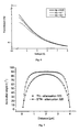
- Fig. 7 -
- Computer modeling of the nematic LC director field at the
light attenuation 320 for standard TN and 220°- twisted LCD light shutter through the LC-molecular layer - Fig. 8 -
- Angular dependence of the light attenuation with HTLS (b) and standard TN LCD light shutter (a)
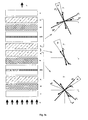
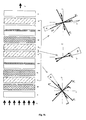
- Fig. 9 -
- Block diagram of the dual complementary LC-cell LCD protective welding light filter, showing in three separate pictures adjacent to the main block diagram the specific polarizer P1, A1 and LC-molecular orientation 1ra, 1rb and the corresponding symmetry axes S1 1, S2 1 in the optically closed state of the first LCD cell LCD1, the specific polarizer P2, A2 and LC-molecular orientation 2ra, 2rb and the corresponding symmetry axes S1 1, S2 1 in the optically closed state of the second LCD cell LCD2, as well as the relative orientation of the polarizers A1 and P2 :
- a. Situation where the light input polarizers P1, respectively P2 are perpendicular within a small angle α to the symmetry axis S1 1 respectively S1 2 through the acute angle between the LC-molecular alignment directions of the first LC-cell LCD1 respectively second LC-cell LCD2
- b. Situation where the light input polarizers P1, respectively P2 are parallel within a small angle α to the symmetry axis S1 1 respectively S1 2 through the acute angle between the LC-molecular alignment directions of the first LC-cell LCD1 respectively the second LC-cell LCD2
- The objective of the present invention is a concept of the LCD light-switching optical filter allowing for very high, electrically controlled, continuously variable light attenuation (up to ≥ 100.000) optimized / symmetrized for the light incidence along the normal to the LCD plane. At the same time the new LCD light-switching optical filter has to exhibit very low light attenuation dependence for the oblique incidence of light within a limited cone of angles off the normal incidence direction (preferably ≥ 15° - see international safety and
quality regulation EN 379 for personal protection optical devices). - According to the invention the problem is solved by specific, novel modification of the general principle of highly twisted nematic LCDs, allowing for "symmetrizing" the overall birefringent properties, which in term results in their angular compensation. In the following exemplary embodiments of the invention are described in detail using
Figures 1 - 9 without limiting the scope of the claims. - High contrast and wide viewing angle in the optically closed state of the LCD light switching filters are achieved using a multilayer laminate comprising two electrically controlled optical birefringent elements - LC-cells LCD1, LCD2, two mutually crossed pairs of polarizing films P1, A1 and P2, A2, adjacent to the light input and output sides of the said LC-cells LCD1, LCD2, each of the said LC-cells LCD1, LCD2 using a thin layer of liquid crystal molecules oriented in a highly twisted configuration (twist angles Φ from 120 to 240 degrees) enclosed between two boundary glass plates 1aa, 1ab, the said plates 1aa, 1ab being on the inner side covered by
transparent electrodes Fig. 1 . Optionally the LC-cells LCD1 respectively LCD2 have additional negative-birefringent compensating layers R1, R2 laminated between them and the adjacent polarizing films P1, A1 respectively P2, A2 in order to further improve the overall optical properties. The block diagram of such LCD light switching filter is shown on theFigs. 9a , b. - As already pointed out before, the highly-twisted LC molecular structure has important advantages for optical light shutter applications (HTLS) as required for LCD light switching filters both from the light transmission/driving voltage characteristics (paragraph #1) as well as overall optical (paragraph #2) performances point of view:
- 1. A pronounced dual slope light transmission / driving voltage characteristics (
Fig. 3 ), which is typical for highly twisted LC structures, as opposed to the standard TN LCD concept (twist angle 90 degrees), turns out to be ideal for light shutter applications. The latter typically operate as "two-state" devices in optically "fully open" and "highly closed" state. For many high performance applications (i.e. eye protection in welding,...) the light attenuation in the optically closed regime however has to be more precisely adjusted to a particular application and therefore further continuous adjustment of the protective "shade" (i.e.EN 379 regulation) is necessary. The adjustments of the light attenuation are therefore done in the "dark scale" rather than in the "gray scale" regime, as found with typical display applications. The low-slope regime of operation LS (Fig. 3 ) of highly twisted LC structures, turns out to be ideal for continuous light attenuation control. The LCD light switching filter operating according to the HTLS concept however has to be adapted to allow for the entire span of the required protective shades to be adjustable within the low slope regime LS. This means that the driving voltage V, applied in the optically closed state to the LC molecular layer da+db+e via thetransparent ITO electrodes Fig. 3 ). In view of this the LC molecular twist angle should be different from 180° for an angle +/-δ as the LC-cells with LC-molecular twist angles Φ ~ 180° cannot provide enough light transmission variation only within the low slope regime LS. From the twist angle dependence of the light transmission / driving voltage characteristics shown in theFig. 3 it is evident that the said angle δ is preferably bigger than 20 degrees. On the other side the maximum value of the said angle δ is limited to ~ 60 degrees by the loss of optical symmetry as well as the overall stability of the highly twisted LC molecular orientation.
There are three technical parameters that can be used to optimize the light transmission / driving voltage characteristics of the LCD light switching filters operating according to the proposed HTLS concept:- 1.1. Twist angle Φ of the LC molecular layer da+db+e structure (see
Fig. 4 ) - 1.2. Relative orientation (angle α) of the crossed polarizing films P1, A1 and the symmetry axes S1 1, S2 1 of the LC-molecular alignment surface directions 1ra, 1rb in the LC-cell LCD1 (see
Fig. 5 ) - 1.3. Chiral doping of the LC molecular layer da+db+e (see
Fig. 6 )
In the following the above features are explained using thefigures 1 through 6 for one LC-cell LCD1. It is however understood that the same explanation can be used also for the second LC-cell LCD 2, which together with the LC-cell LCD1 forms the LCD light switching filter:- Ad 1.1. From the dependence of the light transmission / driving voltage characteristics on the molecular twist angle Φ between the molecular alignment directions 1ra on the light input and 1rb on the light
output boundary layers 1aa, 1ba, 1ca respectively 1ab, 1bb, 1cb of the LC cell LCD1 (seeFig 1a ) it is evident that the twist angle Φ strongly affects the slope of the said characteristics (Fig. 4 ). It is also shown that the limiting value VLS for the onset of the "low slope" regime LS (Fig.3 ) varies with different values of Φ (VLS 240, VLS 210 -Fig. 4 ) - the most sensitive HTLS technical parameter. - Ad 1.2. The relative orientation of the crossed polarizing films P1, A1 and the symmetry axes S1 1, S2 1 of the LC-molecular alignment surface directions 1ra, 1rb in the LC-cell LCD1, as shown on the
Figs. 1 and2 , is the next most sensitive HTLS technical parameter. The light transmission / driving voltage characteristics for various relative angles α (0°, 5°, 10°) shown in theFig. 5 demonstrates that the angle α between the light transmission directions of the crossed polarizing films P1, A1 and the symmetry axes S1 1, S2 1 of the LC-molecular alignment surface directions 1ra, 1rb strongly affects the absolute value of the light attenuation. - Ad 1.3. The chiral doping of the liquid crystal da+db+e also affects the light transmission / driving voltage characteristics. The
Fig 6 shows the said characteristics for various values of chiral doping, where the latter is specified as the ratio d/p, where d is the thickness of the LC-cell LCD1 (typically 4-5 µm) and p is the length of the chiral pitch of the LC molecular structure induced by the chiral dopant (typically - 7 µm to 100 µm). It is obvious that the chiral doping can be also used to some extent to adapt the light transmission / driving voltage characteristics for the specific requirements of the driving electronics.
A point to be emphasized here is that the LCD light switching filters are typically autonomous, battery powered devices. Therefore the performances such as the accuracy of the light attenuation in the optically closed (eye protective) state as well as the overall power consumption of the driving electronics strongly depend on the light transmission/voltage characteristics of the LCD light filters. Optimization of the said characteristics is therefore essential for achieving the state-of -the-art performances. As described above, the HTLS concept provides three technical parameters (Φ, α, d/p) allowing for a precise adaptation of the light transmission / driving voltage characteristics - an important advantage which is not possible with standard TN or Pi-cell technologies. - 1.1. Twist angle Φ of the LC molecular layer da+db+e structure (see
- 2. The highly twisted LC molecular configuration in combination with the use of a dual "complementary" LC-cell filter structure (to be discussed in detail later - paragraph #3) and rotation of the crossed polarizing films away from the symmetry axes between the LC-molecular alignment directions at the LC-cell boundaries for a small angle α, provides an additional optical symmetry essential for the low angular dependence of the light attenuation.
In the following the above features are explained using theFigures 1 and2 for one LC-cell LCD1 only. It is however understood that the same explanation can be used also for the second LC-cell LCD 2, which together with the LC-cell LCD1 forms the LCD light switching filter:
The LC-cells LCD1 and LCD2 are made out of standard alkaline float glass covered with typically 40 nm thick transparent ITO electrically conductive layer widely used in the LCD industry. The LC-cells LCD1 and LCD2 are filled standard commercially available nematic liquid crystal. The highly twisted LC-molecular structure (twist angles Φ from 120 to 240 degrees) of the LC-molecular layer da+db+e in the LC-cell LCD1 is obtained by doping the said nematic liquid crystal with adequate amount (0.05 ≤ d/p ≤ 0.7) of the chiral dopant. The LC-molecules in the said LC-molecular layer da+db+e are further aligned by means of the polymer (typically polyimide) alignment layers 1ca, 1cb on the conductive ITO layers 1ba, 1bb covering the inner sides of the light input and output boundary glass plates 1aa and 1ab so that the alignment directions 1ra, 1rb of the said polymer alignment layers 1ca, 1cb make an angle Φ with respect to each other (seeFig 1a ).
The required symmetry of the light attenuation around the normal to the LC-cell LCD1 is obtained by aligning the crossed polarizing films P1, A1 adjacent to the outer sides of the light input and output boundary glass plates 1aa and 1ab of the LC-cell LCD1 along the symmetry axes S1 1, S2 1 of the LC-molecular alignment surface directions 1ra, 1rb (seeFig. 2 ). Since the final product - LCD light switching filter employs two LC-cells LCD1 and LCD2 in order to be able to provide enough light attenuation, the crossed polarizing films P1, A1 are shifted for a small angle α away from the said ideal orientations along the symmetry axes S1 1, S2 1, as the configurations of the two LC-cells LCD1 and LCD2 can be chosen such that the two LC-cells LCD1 and LCD2 compensate the optical properties of each other. Rotating the crossed polarizing films P1, A1 away from the ideal directions of the LC alignment symmetry axes S1 1, S2 1, however shifts the maximum light attenuation away from the normal to the LC-cell LCD1 plane. With a proper choice of the second LC-cell LCD2 configuration (to be described later - paragraph #3) such a shift of the angular distribution of the light attenuation results in broadening of the viewing angle of the LCD light-switching filter.
The driving voltage V necessary for achieving the specific light attenuation is typically higher with highly twisted LC structures than with standard TN LCDs. Rotation of the crossed polarizing films P1, A1 away from the said ideal directions of the LC alignment symmetry axes S1 1, S2 1 further increases the required amplitude of the driving voltage V. Therefore with the LC-cells, built according to the HTLS concept, the LC-molecular layer da+db+e is subjected to noticeably higher driving voltage V, which in turn results in significantly better homeotropic alignment of the LC molecules in the optically closed state. The said advantage of the HTLS over the standard TN concept is evident from theFig. 7 showing computer modeling of the azimuthal angle θ (characteristic for the homeotropic orientation) of the LC director field through the LC-cell from one boundary plane to the other in the optically closed state (light attenuation 320) for the HTLS and TN LC-cell concept.
As shown in theFig. 7 the HTLS concept exhibits reasonably good homeotropic LC molecular alignment through the entire dark-scale variation, as required for adequate eye protection in the optically closed state of the LCD light switching filter (protective shades 9 through 13 according to theinternational EN 379 safety regulation). This property allows for the efficient angular compensation of the LC-cell LCD1 with just a simple additional negative-birefringent layer R1, the optic axis of which is perpendicular to the LC-cell LCD1 plane. The said negative birefringent layer R1 besides being low cost, easy to manufacture and easy to be tuned to the specific LC-cell, also allows for some superior optical properties (lower light scattering, significantly higher light attenuation,...) compared to the more sophisticated retardation films widely used in the computer and TV industry.
In order to compensate for the angular dependence of the optically birefringent layers (LC-molecular layer, polarizing films, compensating negative-birefringent layer) forming the LCD light switching filter one has to "match" the positive-birefringent properties of the homeotropically aligned central layer of liquid crystal e (seeFig. 1a andFig. 7 ) and the inherently negatively-birefringent polarizing films P1, A1 with the compensating negative-birefringent layer R1. The said layer R1 must have the optic axis perpendicular to the LC-cell LCD1 plane and has to be incorporated between the boundary glass plates 1aa, 1ab of the LC-cell LCD1 and the adjacent polarizing film P1 or A1. The birefringent optical properties of the said birefringent layers depend on the difference An between the refractive indices of the ordinary and extraordinary light ray in the said birefringent layers and their thickness d. In the explanation the following notations will be used: Δne + and de +- difference of the refractive indexes and layer thickness of the homeotropically aligned part of the LC-molecular layer e, Δnp - and dp - - difference of the refractive indexes and layer thickness of the polarizing films P1, A1, ΔnR - and dR - - difference of the refractive indexes and the layer thickness of the negative-birefringent layer R1:- 2.1. In the first approximation the absolute value of the negative optical retardation (ΔnR - x dR -) of the said negative birefringent layer R1 is chosen to be equal to the difference between the absolute value of the positive optical retardation (Δne + x de +) of the homeotropically aligned part of the liquid crystal molecular layer e and the absolute value of the negative optical retardation (Δnp - x dp -) of the polarizing films P1, A1. In this case only the major contribution to the angular dependence originating from the ~homeotropically aligned central part of the LC-molecular layer e is compensated, while the angular dependence of the crossed polarizing films and the thin LC-molecular layers da+db at both boundary surfaces 1ca, 1cb remain uncompensated.
- 2.2. The HTLS structure in the optically closed state exhibits rather high effective residual positive-birefringence in the plane of the LC-cell LCD1, as opposed to the standard TN LCD, where the said effective residual positive birefringence cancels out in the first approximation. The existence of the said residual positive-birefringence in the plane of the LC-cell LCD1 allows also for a higher order of angular compensation using tunable negative-birefringent layer R1 :
The relative positioning of the negative-birefringent layer R1 between the LC-cell LCD1 and the adjacent polarizing films P1, A1 is in principle not arbitrary. A simple qualitative evaluation of the optics of such LCD light switching filter using "Poin-Care sphere" concept shows that one can make advantage of the rather high effective residual positive-birefringence of the thin boundary LC layers da+db to compensate for the angular dependence of the crossed polarizing films. In combination with a positive-birefringent layer having its optic axis perpendicular to the LC-cell plane the said residual birefringence can help reducing the angular dependence of the light attenuation of the crossed polarizing films P1 and A1. The computer modeling of the HTLS LC-cell as described above using GNU LCM-2 modeling software, shows that the value of the effective residual positive-birefringence of the thin boundary LC layers da+db (≈ 80 nm of effective optical retardation) is not sufficient (about 40% too small) for the complete compensation. However even as it is, it can still strongly improve the said angular dependence of the light attenuation of the crossed polarizing films P1 and A1. Instead of adding the above mentioned additional positive-birefringent layer, one can simply "under-compensate" the positive birefringence of the central homeotropically aligned LC layer e, as compared to the condition specified in the preceding paragraph (2.1.) and the resulting overall positive-birefringence can do the job. The whole situation on this level of approximation is rather complex and only the computer modeling can provide a reliable estimate. It shows that any value of "under-compensation" from 100 to 300 nm will significantly improve the overall angular dependence of the LCD light switching filter. The measurements of the angular dependence of the light attenuation for the standard dual complementary TN LCD cell (a) and the negative-birefringent compensation layers compensated dual HTLS LC-cells (b) shown on theFig. 8 confirm this prediction. The scale on the figure is drawn according to theEN 379 regulation -horizontal lines represent the limit of the "quality class 1 and all the regulations are specified for the light incident angles within +/- 15 degrees. It is obvious that the results for the dual HTLS LC-cell light switching filter compensated according to the above concept using the negative-birefringent layer are an order of magnitude better than with the present state-of-the-art products.
As mentioned above the relative positioning of the negative-birefringent compensation layer is not anymore arbitrary in order to be able to use the above concept - the positioning of the negative-birefringent compensation layer R1 depends on the relative orientation of the input polarized light (light input Li polarizing film P1) with respect to the LC-molecular alignment:- 2.2.1. If the light input Li polarizing film P1 is parallel with the symmetry axis S1 1 through the acute angle between the LC alignment directions 1ra, 1rb (
Fig. 1a ) then the negative-birefringent compensation layer R1 has to be built-in between the light input Li polarizing film P1 and the adjacent light input Li boundary glass plate 1aa of the LC-cell LCD1- seeFig. 1a (the situation used in claims 9, 11) - 2.2.2. If the light input Li polarizing film P1 is perpendicular to the symmetry axis S1 1 through the acute angle between the LC alignment directions 1ra, 1rb (
Fig. 1b ,Fig. 2 ) then the negative-birefringent compensation layer R1 has to be built-in between the light output Lo polarizing film A1 and the adjacent light output Lo boundary glass plate 1ab of the LC-cell LCD1 - seeFig. 1b (the situation used inclaims 10, 11).
The detail construction of the above described negative-birefringent layer compensated dual HTLS LC-cell light switching filter is given in the example at the end of this description. - 3. All the above discussed principles of angular compensation of the optical performances are based on the fact that high light attenuation requirements, require the use of two LC-cells in the LCD light-switching filter design. Since these two LC-cells can be constructed such that their optical properties compensate each other to a great deal, just a reasonable improvement of the optical properties of each one of them can result in exceptional performances for the very specific "niche" application. In the case of the LCD light switching filters for eye protection applications the concept of the construction of the "complementary" HTLS LC-cells is rather straightforward. The second LC-cell LCD2 has to fulfill the following requirements in order to be complementary to the first LC-cell LCD1 of the LCD light switching filter:
- 3.1. LC alignment directions 1ra, 1rb in the first LC-cell LCD1 have to be perpendicular within a small angle β to the LC alignment directions 2ra, 2rb in the second LC-cell LCD2
- 3.2. Output light polarizing film A1 adjacent to the light output Lo boundary glass plate 1ab of the first LC-cell LCD1 has to be parallel within a small angle β to the light input Li polarizing film P2 adjacent to the light input Li boundary glass plate 1aa of the second LC-cell LCD2
- 3.3. All other parameters have to be as identical as possible.
The small "misalignment" angle β between the LC-alignment directions 1ra, 1rb as well as the polarizing films P1, A1 of the first LC-cell LCD1 and the LC-alignment directions 2ra, 2rb as well as the polarizing films P2, A2 of the second LC-cell LCD2 needs a further comment. The fact is that from the practical, manufacturing point of view (ease of cutting of the polarizing foils, LC-alignment directions, pretilt of the LC molecules on the alignment surface) it may turn out that the symmetry of the viewing angle would not coincide with the geometry of the LCD light filter. In order to correct for this, the crossed polarizing films P1, A1 and P2, A2, adjacent to the light input and output sides of the said LC-cells LCD1, LCD2 can be laminated to the two LC-cells so that the light output Lo polarizing film A1 laminated on the first LC-cell LCD1 is not perfectly aligned with the light input Li polarizing film P2 on the second LC-cell LCD2. As long as the said misalignment angle β is reasonably small (< 20°) the light loss due to such a misalignment is negligible, however some additional symmetry of the light attenuation correlated with the overall geometry of the LCD light switching filter can be gained. - The use of the proposed HTLS technical solution can be best demonstrated by its application in the automatic LCD light switching filter for eye protection in various welding and plasma cutting applications. Typical working embodiment is described in the Example and illustrated in the
Fig. 8 ,9a andb as follows: - The above described HTLS concept for automatic LCD light filters is in particularly ideal for eye protection in welding applications. Personal protective devices like this have to comply with the international safety regulations like
EN 379, ICNIRP "Guidelines on limits of exposure to broadband incoherent optical radiations", ... Therefore they have to allow for the adjustment of the protective "shade" in the optically closed (protective) state in a rather broad range from -4000 up to ≥ 100.000 times. Furthermore they also have to protect the user not only against strong visible light flashes but also against excessive incoherent light in the invisible but harmful UV and IR light spectrum causing permanent damage to the human eye. The electro-optically active LCD light shutters cannot fulfill the above requirements only by themselves, as they are based on the use of polarizing films, which are developed to be efficient more or less only in the visible light spectrum - an additional protection against invisible UV and IR light is necessary. Since one is dealing with relatively high intensity light sources, this additional protection is preferably achieved by a filter, exhibiting selective reflection rather than absorption in the IR and UV spectral range, while being transparent in the visible spectral range, simulating more or less the eye sensitivity curve - "- photopic filter". Such an additional passive selective "mirror" furthermore guarantees permanent eye protection irrespective of the potential malfunctioning of the active LCD light filtering in the visible spectrum. - In view of this the present state-of-the-art LCD light-switching filters allowing for variable protective shade are typically made as multilayer laminates of at least two electrically controlled optical birefringent elements - LC-cells, adequate number of mutually crossed pairs of polarizing films, adjacent to the light input and output sides of the said LC-cells and on the outer sides having protective cover glass plates, one of which having on its inner side a thin film "photopic" filter layer reflecting harmful IR an UV light (see the block diagram on the
Fig. 9a orb ). - The electrically controlled optical birefringent elements - LC-cells (
Fig. 1 ), which represent the key subcomponets of the LCD light switching filter, are made according to the standard STN LCD production process, using soda-lime glass as the LC-cell boundary plates 1aa, 1ab. In order to generate the driving electric field across the LC layer da+db+e, the boundary glass plates 1aa, 1ab are covered with thetransparent ITO electrodes Fig. 9a ). The negative-birefringent layer R1, having its optic axis perpendicular to the LC-cell LCD1 plane, is subsequently laminated on the light output side of the boundary glass plate 1ab of the LC-cell LCD1. The same process is repeated for the negative-birefringent layer R2 laminated on the second LC-cell LCD2. The same kind of polarizing films (LLC2-5618) are further laminated as the light output polarizing films A1 and A2 on the light output sides of the negative-birefringent layers R1 respectively R2. The two assemblies of LC-cells comprising LC-cells LCD1 and LCD2 with the corresponding polarizing films P1, A1 respectively P2, A2 and negative birefringent layers R1 respectively R2 are subsequently laminated together so that the light output polarizing film A1 of the first assembly and the light input polarizing film P2 of the second assembly are aligned parallel to each other. Finally the whole laminate is covered with the protective glass plates C, the protective glass plate on the light input side being on the side facing the polarizing film P1 covered with a multilayer photopic filter PF selectively reflecting the light in the IR and UV spectrum while transmitting the visible light. - In order to allow for optimal angular compensation of the light attenuation in the optically closed state of the above described LCD-light switching filter for personal protection in welding applications, the values of the compensating negative-birefringent layers R1 and R2 have the same optical retardation which is matched with the positive-birefringent retardation (Δne + x de +) of the homeotropically aligned central layer e of the liquid crystal and the inherent negative-birefringent retardation (Δnp - x dp -) of the polarizing films P1, A1 and P2, A2 in such a way that the absolute value of the optical retardation (ΔnR - x dR -) of the optical compensating layers R1 (= R2) is 200 nm smaller than the difference of the absolute values of the retardation of the homeotropically aligned central layer e of the liquid crystal (Δne + x de +) and the inherent retardation (Δnp - x dp -) of the polarizing films P1, A1 and P2, A2 (for detailed definitions and notations see
paragraph # 2, in particularly 2.2 and 2.3 of the Detailed description):
- As described in detail in the
paragraph # 2, the resulting effective positive birefringence (200nm) with the optic axis perpendicular to the LCD light switching filter plane together with the in-plane effective residual retardation of the boundary layers da, db of the LC-molecular layer allow for very efficient overall angular compensation of the light attenuation of the LCD light switching filter in the optically closed state. - The measurements of the angular dependence of the light attenuation of the LCD light switching manufactured according to the above Example (b) compared to the standard dual complementary TN LCD cell (a) are shown on the
Fig. 8 . The scale on the figure is drawn according to theEN 379 regulation -horizontal lines represent the limits of the "quality class 1 and all the regulations are specified for the light incident angles within +/- 15 degrees. It is obvious that the results for the dual HTLS LC-cell light switching filter are an order of magnitude better than with the present state-of-the-art products. - It should be however emphasized, that the described Example represents only one feasible working embodiment of the angularly compensated LCD welding filter according to the invention. Various modifications and variations can be made within the scope of this invention as defined in the appended claims.
- A typical example of a possible modification is shown on the
Fig. 9b , where the polarization (P1, P2) of the incoming light is parallel to the symmetry axes S1 1 respectively S1 2 of the LC-molecular orientation in the LC-cells LCD1, respectively LCD2 and not perpendicular, as assumed in the EXAMPLE. Such a change of the relative polarization direction with respect to the symmetry axes S1 1 respectively S1 2 of the LC-molecular orientation results in the "shift" of the retardation layers R1, respectively R2 from the light output sides of the LC-cells LCD1 respectively LCD2,to the light input positions.
Claims (9)
- Liquid Crystal, LC, light switching filter comprising two electrically controlled LC-cells (LCD1, LCD2), two pairs of mutually crossed polarizing films (P1, A1; P2, A2), the polarising films (P1, A1; P2, A2) being respectively disposed adjacent to light input and output sides of the said LC cells (LCD1, LCD2), each of the said LC-cells (LCD1, LCD2) having a thin liquid crystal molecular layer (da+db+e) of highly twisted liquid crystal enclosed between two boundary glass plates (1aa, 1ab), the said plates (1aa, 1ab) being on an inner side covered by transparent electrodes (1ba, 1bb) and alignment layers (1ca, 1cb), wherein the alignment layers (1ca, 1cb) on the transparent electrodes (1ba, 1bb) covering the boundary glass plates (1aa, 1ab) of both LC cells (LCD1, LCD2) are oriented in such a way that in the optically open state of the LC light switching filter, when no driving electric voltage (V=0) is applied to the transparent electrodes (1ba, 1bb), the liquid crystal molecular layer (da+db+e) adopts a highly twisted molecular orientation with twist angles Φ between 120° to 240° , the twist angle Φ of the molecular orientation being selected to be different from 180 degrees by an angle +/δ, where δ can adopt any value in the interval from 10 degrees to 60 degrees,
wherein the two pairs of crossed polarizing films (P1, A1 and P2, A2) are oriented with respect to LC molecular alignment surface directions (1ra, 1rb respectively 2ra, 2rb) of each of the LC cells (LCD1, LCD2) in such a way that the light transmission axes of a first (P1, A1) of said pairs of polarizing films are respectively aligned away from the bisectrices (S1 1, S2 1) of the LC-molecular alignment surface directions (1ra, 1rb) in a first LC-cell (LCD1) by a small angle α, and that the light transmission axes of the second (P2, A2) of said pairs of polarizing films are respectively aligned away from the bisectrices (S1 2, S2 2) of the LC-molecular alignment surface directions (2ra, 2rb) in the second LC-cell (LCD2) by a small angle α, wherein said angle α is smaller than 20 degrees, and
wherein said two LC-cells (LCD1, LCD2) have a complementary configuration, in which all technical parameters are identical except for the liquid crystal molecular alignment directions (2ra, 2rb) of the second LC-cell (LCD2), which are rotated by 90 degrees with respect to those of the first LC-cell (LCD1), so that the bisectrix (S1 2) through an acute angle between the molecular alignment directions (2ra, 2rb) of the second LC-cell (LCD2) is perpendicular to the bisectrix (S1 1) through an acute angle between the molecular alignment directions (1ra, 1rb) of the first LC-cell (LCD1). - LC light switching filter according to claim 1, wherein the LC-cells (LCD1, LCD2) are arranged to provide a light transmission / driving voltage characteristics of relatively high transmission at driving voltages lower than a threshold voltage Vth followed by a steep decay to relatively low transmission with increasing driving voltages as a first regime and a further less inclined decay of transmission beginning at a limiting driving voltage VLS with further increasing driving voltages as a second, low-slope regime (LS), and wherein the LC light switching filter is adapted to be operated in the second regime of the light transmission / driving voltage characteristics of the LC-cells (LCD1, LCD2) in an optically-closed field on state, wherein the light attenuation is varied only within the second regime being always greater than a factor of 10.
- LC light switching filter according to claim 1 or 2, wherein the twist angle Φ of the molecular orientation is selected to be close to the value 135 degrees or close to the value 225 degrees.
- LC light switching filter according to any of the claims 1 to 3, wherein said angle α between said first pair of crossed polarizing films (P1, A1) and said bisectrices (S1 1, S2 1) in said first LC-cell (LCD1) and between said second pair of crossed polarizing films (P2, A2) and said bisectrices (S1 2, S2 2) in said second LC-cell (LCD2) is adjusted to maximize the overall viewing angle, while keeping the light attenuation within a cone of +/- 15 degrees around the normal to the LC light switching filter such that even at a maximum light attenuation factor of 100.000 said light attenuation varies less than for a factor 1.6 around the average value within said 15 degree cone angle and wherein
the transmission axis of a light output polarizing film (A1) of said first (P1, A1) of said pairs of polarizing films of the first LC-cell (LCD1) is aligned to be parallel within a small angle β to the transmission axis of a light input polarizing film (P2) of said second (P2, A2) of said pairs of polarizing films of the second LC-cell (LCD2) and wherein the said angle β is smaller than 20 degrees. - LC light switching filter according to any of the claims 1 to 4, wherein
a concentration of a chiral dopant in the said liquid crystal molecular layer (da+db+e) is in the range between concentrations causing 5% and concentrations causing 120% of the twist angle Φ of the molecular orientation within said liquid crystal molecular layer (da+db+e), when no driving voltage (V) is applied to it. - LC light switching filter according to any of the claims 1 to 5
further having a built-in negative-birefringent layer (R1) between either one of said boundary glass plates (1aa, 1ab) of the first LC-cell (LCD1) and the adjacent polarizing film (P1) or (A1) of said first (P1, A1) of said pairs of polarizing films and a negative-birefringent layer (R2) between either one of said boundary glass plates (2aa, 2ab) of the second LC-cell (LCD2) and the adjacent polarizing film (P2) or (A2) of said second (P2, A2) of said pairs of polarizing films, wherein
said negative-birefringent layers (R1, R2), an optical axis of which is perpendicular to the LC light switching filter plane, exhibit the same negative optical retardation Δ nR - x dR - were ΔnR - is the difference between the refractive indices of the ordinary and extraordinary light ray in said negative-birefringent layers (R1, R2) and dR - is the thickness of said negative-birefringent layers (R1, R2), and wherein
an absolute value of a negative optical retardation ΔnR - x dR - of said negative-birefringent layers (R1, R2) is selected to be equal to the difference between an absolute value of a positive optical retardation Δne + x de + of a homeotropically aligned part of the liquid crystal molecular layer (e) in said LC-cells (LCD1, LCD2) in an optically-closed field-on state and an absolute value of a negative optical retardation Δnp - x dp - of said pairs of polarizing films (P1, A1, P2, A2), where
Δne + is the difference between the refractive indices of the ordinary and extraordinary light ray in said homeotropically aligned part of the liquid crystal molecular layer (e) in an optically-closed field-on state, de + is the thickness of said homeotropically aligned liquid crystal molecular layer (e) and Δnp - is the difference between the refractive indices of the ordinary and extraordinary light ray in the polarizing films (P1, A1, P2, A2) while dp - is the thickness of said polarizing films (P1, A1, P2, A2). - LC light switching filter according to any of the claims 1 to 5, wherein
a light input polarizing film (P1) of a first (P1, A1) of said pairs of polarizing films for the first LC-cell (LCD1) is parallel within a small angle α to the bisectrix (S1 1) through an acute angle between the LC molecular alignment directions (1ra, 1rb) of the first LC-cell (LCD1), and a light input polarizing film (P2) of a second (P2, A2) of said pairs of polarizing films for the second LC-cell (LCD2) is parallel within a small angle α to the bisectrix (S1 2) through an acute angle between the liquid crystal molecular alignment directions (2ra, 2rb) of the second LC-cell (LCD2), said angle α being larger than σ degrees and smaller than 20 degrees, and wherein
said LC light switching filter further has a built-in negative-birefringent layer (R1) between the light input boundary glass plate (1aa) of the first LC-cell (LCD1) and the adjacent light input polarizing film (P1) and a negative-birefringent layer (R2) between the light input boundary glass plate (1aa 2) of the second LC-cell (LCD2) and the adjacent light input polarizing film (P2), and wherein
both said negative-birefringent layers (R1, R2), optical axes of which are perpendicular to the LC light switching filter plane, exhibit the same negative optical retardation ΔnR - x dR -, where ΔnR - is the difference between the refractive indices of the ordinary and extraordinary light ray in said negative-birefringent layers (R1, R2) and dR - is the thickness of said negative-birefringent layers (R1, R2), and wherein
an absolute value of a negative optical retardation ΔnR - x dR - of said negative-birefringent layers (R1, R2) is selected to be smaller than the difference between an absolute value of a positive optical retardation Δne + x de + of a homeotropically aligned part of the liquid crystal molecular layer (e) in the LC-cells (LCD1, LCD2) in an optically-closed field-on state and an absolute value of a negative optical retardation Δnp - x dp - of said pairs of polarizing films (P1, A1, P2, A2) so that a resulting positive optical retardation (Δne + x de +) - (Δnp - x dp -) - (ΔnR - x dR -) in the direction of the normal to the LC light switching filter, in combination with an in-plane residual positive optical retardation of boundary parts of the liquid crystal molecular layer (da, db) in both LC-cells (LCD1, LCD2) in an optically-closed field-on state allows for additional compensation of the angular dependence of the pairs of crossed polarizing films (P1, A1 and P2, A2), where
Δne + is the difference between the refractive indices of the ordinary and extraordinary light ray in said homeotropically aligned part of the liquid crystal molecular layer (e) in an optically-closed field-on state, de + is the thickness of said homeotropically aligned part of the liquid crystal molecular layer (e) and Δnp - is the difference between the refractive indices of the ordinary and extraordinary light ray in the polarizing films (P1, A1, P2, A2) while dp - is the thickness of the said polarizing films (P1, A1, P2, A2). - LC light switching filter according to any of the claims 1 to 5, wherein
a light input polarizing film (P1) of a first (P1, A1) of said pairs of polarizing films for the first LC-cell (LCD1) is perpendicular within a small angle α to the bisectrix (S1 1) through an acute angle between the LC molecular alignment directions (1ra, 1rb) of the first LC-cell (LCD1) and a light input polarizing film (P2) of a second (P2, A2) of said pairs of polarizing films for the second LC-cell (LCD2) is perpendicular within a small angle α to the bisectrix (S1 2) through an acute angle between the liquid crystal molecular alignment directions (2ra, 2rb) of the second LC-cell (LCD2), said angle α being larger than σ degrees and smaller than 20 degrees, and wherein
said LC light switching filter further has a built-in negative-birefringent layer (R1) between the light output boundary glass plate (1ab) of the first LC-cell (LCD1) and the adjacent light output polarizing film (A1) and a negative-birefringent layer (R2) between the light output boundary glass plate (2ab) of the second LC-cell (LCD2) and the adjacent light output polarizing film (A2), and wherein
both said negative-birefringent layers (R1, R2), optic axes of which are perpendicular to a LCD light switching filter plane, exhibit the same negative optical retardation ΔnR - x dR -, where ΔnR - is the difference between the refractive indices of the ordinary and extraordinary light ray in said negative-birefringent layers (R1, R2) and dR - is the thickness of said negative-birefringent layers (R1, R2), and wherein
an absolute value of the negative optical retardation ΔnR - x dR - of said negative-birefringent layers (R1, R2) is selected to be smaller than the difference between an absolute value of a positive optical retardation Δne + x de + of a homeotropically aligned part of the liquid crystal molecular layer (e) in the LC-cells (LCD1, LCD2) in an optically-closed field-on state and an absolute value of a negative optical retardation Δnp - x dp - of said pairs of polarizing films (P1, A1, P2, A2) so that a resulting positive optical retardation (Δne + x de +) - (Δnp - x dp -) - (ΔnR - x dR -) in the direction of the normal to the LC light switching filter, in combination with an in-plane residual positive optical retardation of boundary parts of the liquid crystal molecular layer (da, db) in both LC-cells (LCD1, LCD2) in an optically-closed field-on state allows for additional compensation of an angular dependence of the pairs of crossed polarizing films ( P1, A1 and P2, A2), where
Δne + is the difference between the refractive indices of the ordinary and extraordinary light ray in the homeotropically aligned part of the liquid crystal molecular layer (e) in an optically-closed field-on state, de + is the thickness of said homeotropically aligned part of the liquid crystal molecular layer (e) and Δnp - is the difference between the refractive indices of the ordinary and extraordinary light ray in the polarizing films (P1, A1, P2, A2) while dp - is the thickness of the said polarizing films (P1, A1, P2, A2). - LC light switching filter according to claims 7 or 8 wherein the thickness dR - of the said negative-birefringent layers (R1, R2) is selected to be such that the absolute value of their negative optical retardation ΔnR - x dR - is at least 100 nm but not more than 250 nm smaller than the difference between the absolute value of the positive optical retardation Δne + x de + of the homeotropically aligned part of the liquid crystal molecular layer (e) in the LC-cells (LCD1, LCD2) in an optically-closed field-on state and an absolute value of the negative optical retardation Δnp - x dp - of the said pairs of polarizing films (P1, A1, P2, A2).
Applications Claiming Priority (2)
| Application Number | Priority Date | Filing Date | Title |
|---|---|---|---|
| SI200500147A SI22066A (en) | 2005-05-20 | 2005-05-20 | Liquid crystal switchable light filter with adjustable contrast and wide visual angle |
| PCT/EP2006/004336 WO2006122679A1 (en) | 2005-05-20 | 2006-05-09 | Variable contrast, wide viewing angle liquid crystal light attenuation filter |
Publications (2)
| Publication Number | Publication Date |
|---|---|
| EP1883854A1 EP1883854A1 (en) | 2008-02-06 |
| EP1883854B1 true EP1883854B1 (en) | 2010-06-30 |
Family
ID=36694475
Family Applications (1)
| Application Number | Title | Priority Date | Filing Date |
|---|---|---|---|
| EP06753533A Ceased EP1883854B1 (en) | 2005-05-20 | 2006-05-09 | Variable contrast, wide viewing angle liquid crystal light attenuation filter |
Country Status (5)
| Country | Link |
|---|---|
| US (1) | US8026998B2 (en) |
| EP (1) | EP1883854B1 (en) |
| DE (1) | DE602006015183D1 (en) |
| SI (1) | SI22066A (en) |
| WO (1) | WO2006122679A1 (en) |
Families Citing this family (4)
| Publication number | Priority date | Publication date | Assignee | Title |
|---|---|---|---|---|
| US8638400B2 (en) * | 2010-07-13 | 2014-01-28 | Reald Inc. | Field-of-view compensated polarization switch for short-throw 3D projection |
| US20120109264A1 (en) * | 2010-10-28 | 2012-05-03 | Solta Medical, Inc. | Devices and methods for tissue treatment across a large surface area |
| CN106361495A (en) * | 2016-10-31 | 2017-02-01 | 亚世光电(鞍山)有限公司 | High-class LCD welding goggles |
| JP6820420B2 (en) | 2016-11-11 | 2021-01-27 | エシロール・アンテルナシオナル | Phase modulator and optics |
Citations (2)
| Publication number | Priority date | Publication date | Assignee | Title |
|---|---|---|---|---|
| US5572343A (en) * | 1992-05-26 | 1996-11-05 | Olympus Optical Co., Ltd. | Visual display having see-through function and stacked liquid crystal shutters of opposite viewing angle directions |
| US20010035925A1 (en) * | 1996-05-10 | 2001-11-01 | Citizen Watch Co., Ltd. | Liquid crystal shutter and method of driving the same |
Family Cites Families (11)
| Publication number | Priority date | Publication date | Assignee | Title |
|---|---|---|---|---|
| US4039254A (en) * | 1976-05-27 | 1977-08-02 | Mack Gordon | Electro-optic welding lens assembly using multiple liquid crystal light shutters and polarizers |
| US4696548A (en) * | 1984-06-08 | 1987-09-29 | Nippon Soken, Inc. | Antiglare mirror for an automobile |
| DE3721751A1 (en) | 1987-07-01 | 1989-01-12 | Eps Elektronik | Optoelectronic filter preferably for video cameras |
| JPH04194820A (en) * | 1990-11-22 | 1992-07-14 | Sharp Corp | Liquid crystal display device |
| WO1993013449A1 (en) * | 1991-12-26 | 1993-07-08 | Osd Envizion Company | Eye protection device for welding helmets and the like |
| SE502868C2 (en) | 1994-04-26 | 1996-02-05 | Hoernell Elektrooptik Ab | Welding quick filter with improved angular properties |
| SE509569C2 (en) | 1995-10-26 | 1999-02-08 | Hoernell International Ab | Liquid crystal shutter construction |
| SE508272C2 (en) | 1995-10-26 | 1998-09-21 | Hoernell International Ab | Liquid crystal shutter assembly, and a light shading device comprising such a structure |
| US5940155A (en) * | 1997-09-04 | 1999-08-17 | International Business Machines Corporation | Liquid crystal displays containing tilted optical axis compensation films having a negative birefringence |
| SI21526A (en) | 2003-05-16 | 2004-12-31 | Institut "Jožef Stefan" | High contrast, wide viewing angle lcd light-switching element |
| US7458442B2 (en) | 2005-03-23 | 2008-12-02 | Honeywell International Inc. | Electric brake having parking brake function |
-
2005
- 2005-05-20 SI SI200500147A patent/SI22066A/en not_active IP Right Cessation
-
2006
- 2006-05-09 WO PCT/EP2006/004336 patent/WO2006122679A1/en not_active Ceased
- 2006-05-09 US US11/920,323 patent/US8026998B2/en not_active Expired - Fee Related
- 2006-05-09 DE DE602006015183T patent/DE602006015183D1/en not_active Expired - Lifetime
- 2006-05-09 EP EP06753533A patent/EP1883854B1/en not_active Ceased
Patent Citations (2)
| Publication number | Priority date | Publication date | Assignee | Title |
|---|---|---|---|---|
| US5572343A (en) * | 1992-05-26 | 1996-11-05 | Olympus Optical Co., Ltd. | Visual display having see-through function and stacked liquid crystal shutters of opposite viewing angle directions |
| US20010035925A1 (en) * | 1996-05-10 | 2001-11-01 | Citizen Watch Co., Ltd. | Liquid crystal shutter and method of driving the same |
Also Published As
| Publication number | Publication date |
|---|---|
| EP1883854A1 (en) | 2008-02-06 |
| US20090066882A1 (en) | 2009-03-12 |
| WO2006122679A1 (en) | 2006-11-23 |
| DE602006015183D1 (en) | 2010-08-12 |
| SI22066A (en) | 2006-12-31 |
| US8026998B2 (en) | 2011-09-27 |
Similar Documents
| Publication | Publication Date | Title |
|---|---|---|
| US8542334B2 (en) | Variable contrast, wide viewing angle LCD light-switching filter | |
| US8314918B2 (en) | Display | |
| US9116370B2 (en) | Liquid crystal light variable device | |
| US7405780B2 (en) | Liquid-crystal display | |
| US20120105775A1 (en) | Circular polarizer, liquid crystal display device, and terminal device | |
| EP3617769B1 (en) | Transmittance variable device | |
| CN101859043B (en) | Liquid crystal shutter and image display observation system | |
| EP1152282A1 (en) | Liquid-crystal display device | |
| JP2005352068A (en) | Liquid crystal display device | |
| KR101884639B1 (en) | Liquid crystal display device | |
| US7164457B2 (en) | Liquid crystal display | |
| EP1625445B1 (en) | High contrast, wide viewing angle lcd light-switching element | |
| US8026998B2 (en) | Variable contrast, wide viewing angle liquid crystal light attenuation filter | |
| US20130271680A1 (en) | Liquid crystal panel, and liquid crystal display | |
| CN102279472B (en) | Stereo image identifying device | |
| WO2012090839A1 (en) | Liquid-crystal panel and liquid-crystal display | |
| US20090213312A1 (en) | Single-polarizer reflective bistable twisted nematic (btn) liquid crystal display device | |
| JP5581125B2 (en) | Stereoscopic image recognition device | |
| JP4714188B2 (en) | Liquid crystal display device | |
| JP4749391B2 (en) | Liquid crystal display | |
| KR20190037955A (en) | Optical Device | |
| JP2007249244A (en) | Liquid crystal display | |
| JP5650911B2 (en) | Liquid crystal display element | |
| JPH0139084B2 (en) | ||
| JP3090020B2 (en) | Liquid crystal display device |
Legal Events
| Date | Code | Title | Description |
|---|---|---|---|
| PUAI | Public reference made under article 153(3) epc to a published international application that has entered the european phase |
Free format text: ORIGINAL CODE: 0009012 |
|
| 17P | Request for examination filed |
Effective date: 20071010 |
|
| AK | Designated contracting states |
Kind code of ref document: A1 Designated state(s): CH DE FR GB LI |
|
| 17Q | First examination report despatched |
Effective date: 20080506 |
|
| RBV | Designated contracting states (corrected) |
Designated state(s): CH DE FR GB LI |
|
| DAX | Request for extension of the european patent (deleted) | ||
| GRAC | Information related to communication of intention to grant a patent modified |
Free format text: ORIGINAL CODE: EPIDOSCIGR1 |
|
| GRAP | Despatch of communication of intention to grant a patent |
Free format text: ORIGINAL CODE: EPIDOSNIGR1 |
|
| GRAS | Grant fee paid |
Free format text: ORIGINAL CODE: EPIDOSNIGR3 |
|
| GRAA | (expected) grant |
Free format text: ORIGINAL CODE: 0009210 |
|
| AK | Designated contracting states |
Kind code of ref document: B1 Designated state(s): CH DE FR GB LI |
|
| REG | Reference to a national code |
Ref country code: CH Ref legal event code: EP Ref country code: GB Ref legal event code: FG4D |
|
| REF | Corresponds to: |
Ref document number: 602006015183 Country of ref document: DE Date of ref document: 20100812 Kind code of ref document: P |
|
| REG | Reference to a national code |
Ref country code: CH Ref legal event code: NV Representative=s name: RENTSCH & PARTNER |
|
| PLBE | No opposition filed within time limit |
Free format text: ORIGINAL CODE: 0009261 |
|
| STAA | Information on the status of an ep patent application or granted ep patent |
Free format text: STATUS: NO OPPOSITION FILED WITHIN TIME LIMIT |
|
| 26N | No opposition filed |
Effective date: 20110331 |
|
| REG | Reference to a national code |
Ref country code: CH Ref legal event code: PFA Owner name: INSTITUT JOZEF STEFAN Free format text: INSTITUT JOZEF STEFAN#JAMOVA 39#1000 LJUBLJANA (SI) -TRANSFER TO- INSTITUT JOZEF STEFAN#JAMOVA 39#1000 LJUBLJANA (SI) |
|
| REG | Reference to a national code |
Ref country code: DE Ref legal event code: R097 Ref document number: 602006015183 Country of ref document: DE Effective date: 20110330 |
|
| REG | Reference to a national code |
Ref country code: FR Ref legal event code: PLFP Year of fee payment: 10 |
|
| REG | Reference to a national code |
Ref country code: FR Ref legal event code: PLFP Year of fee payment: 11 |
|
| REG | Reference to a national code |
Ref country code: FR Ref legal event code: PLFP Year of fee payment: 12 |
|
| REG | Reference to a national code |
Ref country code: CH Ref legal event code: PCAR Free format text: NEW ADDRESS: BELLERIVESTRASSE 203 POSTFACH, 8034 ZUERICH (CH) |
|
| REG | Reference to a national code |
Ref country code: FR Ref legal event code: PLFP Year of fee payment: 13 |
|
| PGFP | Annual fee paid to national office [announced via postgrant information from national office to epo] |
Ref country code: DE Payment date: 20190521 Year of fee payment: 14 |
|
| PGFP | Annual fee paid to national office [announced via postgrant information from national office to epo] |
Ref country code: FR Payment date: 20190527 Year of fee payment: 14 |
|
| PGFP | Annual fee paid to national office [announced via postgrant information from national office to epo] |
Ref country code: CH Payment date: 20190604 Year of fee payment: 14 |
|
| PGFP | Annual fee paid to national office [announced via postgrant information from national office to epo] |
Ref country code: GB Payment date: 20190521 Year of fee payment: 14 |
|
| REG | Reference to a national code |
Ref country code: DE Ref legal event code: R119 Ref document number: 602006015183 Country of ref document: DE |
|
| PG25 | Lapsed in a contracting state [announced via postgrant information from national office to epo] |
Ref country code: LI Free format text: LAPSE BECAUSE OF NON-PAYMENT OF DUE FEES Effective date: 20200531 Ref country code: CH Free format text: LAPSE BECAUSE OF NON-PAYMENT OF DUE FEES Effective date: 20200531 |
|
| GBPC | Gb: european patent ceased through non-payment of renewal fee |
Effective date: 20200509 |
|
| PG25 | Lapsed in a contracting state [announced via postgrant information from national office to epo] |
Ref country code: FR Free format text: LAPSE BECAUSE OF NON-PAYMENT OF DUE FEES Effective date: 20200531 Ref country code: GB Free format text: LAPSE BECAUSE OF NON-PAYMENT OF DUE FEES Effective date: 20200509 |
|
| PG25 | Lapsed in a contracting state [announced via postgrant information from national office to epo] |
Ref country code: DE Free format text: LAPSE BECAUSE OF NON-PAYMENT OF DUE FEES Effective date: 20201201 |