EP1883785B1 - Sensing coil assembly and method for attaching a sensing coil in a fiber optic gyroscope - Google Patents
Sensing coil assembly and method for attaching a sensing coil in a fiber optic gyroscope Download PDFInfo
- Publication number
- EP1883785B1 EP1883785B1 EP06771006.1A EP06771006A EP1883785B1 EP 1883785 B1 EP1883785 B1 EP 1883785B1 EP 06771006 A EP06771006 A EP 06771006A EP 1883785 B1 EP1883785 B1 EP 1883785B1
- Authority
- EP
- European Patent Office
- Prior art keywords
- sensing coil
- adhesive
- preformed
- support surface
- preformed adhesive
- Prior art date
- Legal status (The legal status is an assumption and is not a legal conclusion. Google has not performed a legal analysis and makes no representation as to the accuracy of the status listed.)
- Ceased
Links
- 239000000835 fiber Substances 0.000 title claims description 44
- 238000000034 method Methods 0.000 title claims description 23
- 239000000853 adhesive Substances 0.000 claims description 87
- 230000001070 adhesive effect Effects 0.000 claims description 87
- 239000013307 optical fiber Substances 0.000 claims description 22
- 239000000463 material Substances 0.000 claims description 15
- 229920000642 polymer Polymers 0.000 claims description 11
- 230000006835 compression Effects 0.000 claims description 6
- 238000007906 compression Methods 0.000 claims description 6
- 230000036316 preload Effects 0.000 claims 2
- 239000011521 glass Substances 0.000 description 12
- 230000007613 environmental effect Effects 0.000 description 5
- VYPSYNLAJGMNEJ-UHFFFAOYSA-N Silicium dioxide Chemical group O=[Si]=O VYPSYNLAJGMNEJ-UHFFFAOYSA-N 0.000 description 4
- 230000008878 coupling Effects 0.000 description 4
- 238000010168 coupling process Methods 0.000 description 4
- 238000005859 coupling reaction Methods 0.000 description 4
- 239000004593 Epoxy Substances 0.000 description 3
- 239000002131 composite material Substances 0.000 description 3
- 238000004519 manufacturing process Methods 0.000 description 3
- 239000000919 ceramic Substances 0.000 description 2
- 239000011248 coating agent Substances 0.000 description 2
- 238000000576 coating method Methods 0.000 description 2
- 238000013016 damping Methods 0.000 description 2
- 239000011152 fibreglass Substances 0.000 description 2
- 239000007788 liquid Substances 0.000 description 2
- 230000003287 optical effect Effects 0.000 description 2
- ZOXJGFHDIHLPTG-UHFFFAOYSA-N Boron Chemical compound [B] ZOXJGFHDIHLPTG-UHFFFAOYSA-N 0.000 description 1
- OKTJSMMVPCPJKN-UHFFFAOYSA-N Carbon Chemical compound [C] OKTJSMMVPCPJKN-UHFFFAOYSA-N 0.000 description 1
- RTAQQCXQSZGOHL-UHFFFAOYSA-N Titanium Chemical compound [Ti] RTAQQCXQSZGOHL-UHFFFAOYSA-N 0.000 description 1
- 230000002411 adverse Effects 0.000 description 1
- 239000004760 aramid Substances 0.000 description 1
- 229920003235 aromatic polyamide Polymers 0.000 description 1
- 230000005540 biological transmission Effects 0.000 description 1
- 230000015572 biosynthetic process Effects 0.000 description 1
- 229910052796 boron Inorganic materials 0.000 description 1
- -1 carbide Chemical compound 0.000 description 1
- 238000006243 chemical reaction Methods 0.000 description 1
- 150000001875 compounds Chemical class 0.000 description 1
- 238000010276 construction Methods 0.000 description 1
- 230000008602 contraction Effects 0.000 description 1
- WUUZKBJEUBFVMV-UHFFFAOYSA-N copper molybdenum Chemical compound [Cu].[Mo] WUUZKBJEUBFVMV-UHFFFAOYSA-N 0.000 description 1
- SBYXRAKIOMOBFF-UHFFFAOYSA-N copper tungsten Chemical compound [Cu].[W] SBYXRAKIOMOBFF-UHFFFAOYSA-N 0.000 description 1
- 230000003247 decreasing effect Effects 0.000 description 1
- 230000007547 defect Effects 0.000 description 1
- 229910002804 graphite Inorganic materials 0.000 description 1
- 239000010439 graphite Substances 0.000 description 1
- 230000002706 hydrostatic effect Effects 0.000 description 1
- 238000003754 machining Methods 0.000 description 1
- 229910052751 metal Inorganic materials 0.000 description 1
- 239000002184 metal Substances 0.000 description 1
- 239000002905 metal composite material Substances 0.000 description 1
- 229910001092 metal group alloy Inorganic materials 0.000 description 1
- 239000011156 metal matrix composite Substances 0.000 description 1
- 238000004382 potting Methods 0.000 description 1
- 238000004663 powder metallurgy Methods 0.000 description 1
- 230000001902 propagating effect Effects 0.000 description 1
- 230000006903 response to temperature Effects 0.000 description 1
- 229910052710 silicon Inorganic materials 0.000 description 1
- 239000010703 silicon Substances 0.000 description 1
- 239000007787 solid Substances 0.000 description 1
- 239000010936 titanium Substances 0.000 description 1
- 229910052719 titanium Inorganic materials 0.000 description 1
- 238000004804 winding Methods 0.000 description 1
Images


Classifications
-
- G—PHYSICS
- G01—MEASURING; TESTING
- G01C—MEASURING DISTANCES, LEVELS OR BEARINGS; SURVEYING; NAVIGATION; GYROSCOPIC INSTRUMENTS; PHOTOGRAMMETRY OR VIDEOGRAMMETRY
- G01C19/00—Gyroscopes; Turn-sensitive devices using vibrating masses; Turn-sensitive devices without moving masses; Measuring angular rate using gyroscopic effects
- G01C19/58—Turn-sensitive devices without moving masses
- G01C19/64—Gyrometers using the Sagnac effect, i.e. rotation-induced shifts between counter-rotating electromagnetic beams
- G01C19/72—Gyrometers using the Sagnac effect, i.e. rotation-induced shifts between counter-rotating electromagnetic beams with counter-rotating light beams in a passive ring, e.g. fibre laser gyrometers
- G01C19/721—Details, e.g. optical or electronical details
- G01C19/722—Details, e.g. optical or electronical details of the mechanical construction
Definitions
- the present invention generally relates to fiber optic gyroscope systems, and more particularly relates to an attachment system and method for attaching a sensing coil in a fiber optic gyroscope system.
- Gyroscopes have been used to measure rotation rates or changes in angular velocity about an axis.
- a basic conventional fiber optic gyroscope includes a light source, a beam generating device (e.g., a beam-splitter), and a coil of optical fiber coupled to the beam generating device that encircles an area.
- the beam generating device transmits light beams originating from the light source into the coil of optical fiber, and these light beams propagate in a clockwise (CW) direction and a counter-clockwise (CCW) direction along the core of the optical fiber.
- CW clockwise
- CCW counter-clockwise
- the two counter-propagating (e.g., CW and CCW) beams experience different pathlengths while propagating around a rotating path, and the difference between the two pathlengths produces a phase difference between the two counter-propagating beams that is proportional to the rotational rate.
- FOGs utilize a glass-based optical fiber to conduct light along a solid core of the fiber over long distances with low loss and distortion.
- This optical fiber has a glass/silica core surrounded by a polymer jacket, or buffer, and may be wound into a cylindrical structure, such as a coil, and affixed to a coil-supporting structure, such as a cylindrical hub, to form a sensing coil.
- the hub and fiber optic coil are both substantially cylindrical structures oriented about a center axis, and the hub has a relatively smaller radius than the radius of the fiber optic coil.
- An adhesive coating between the outer surface of the hub and inner surface of the fiber optic coil may be used affix the fiber optic coil to the hub.
- the glass/silica core and the polymer buffer may each respond differently to a variety of environmental factors and thereby adversely affect the pathlength difference between the two counter-propagating waves.
- Some of these environmental factors include temperature and mechanical strain that may create a bias between the phases of the two counter-propagating waves such that the output of the sensing coil yields a phase difference between the two counter-propagating waves that is indistinguishable from a rotation-induced phase difference.
- a FOG may be placed in an environment having a fluctuating ambient temperature. Temperature variations affect the sensing coil in two ways: first, the sensing coil undergoes mechanical strain as a result of a differential thermal expansion; and second, the optical transmission properties of the optical fiber change with the temperature.
- a Coefficient of Thermal Expansion (CTE) mismatch between the glass/silica core and the polymer buffer may result in a transverse expansion of the fiber optic coil that is significantly larger than the lengthwise expansion of the fiber optic coil.
- CTE Thermal Expansion
- the radial expansion of the fiber optic coil, constrained by the glass/silica core of the optical fiber is significantly smaller than the axial expansion of the fiber optic coil that is dominated by the large CTE of the polymer buffer.
- the outer diameter of the fiber optic coil generally expands radially away from the center axis of the fiber optic coil while the inner diameter of the fiber optic coil generally expands radially toward the center axis of the fiber optic coil.
- the hub may also expand in response to temperature fluctuations.
- a hub made from an isotropic material may expand relatively uniformly in both the axial direction and in the radial direction with respect to the center axis.
- the hub radially expands faster than the fiber optic coil expands, as a whole, and imparts stress on the fiber optic coil.
- the radial expansion of the hub against the opposite expansion direction of the inner diameter of the fiber optic coil may produce significant mechanical interference between theses components resulting in an outward radial pressure exerted at the fiber optic coil interface that induces stresses in the coil structure.
- One method of applying the compliant adhesive is to inject a liquid adhesive, such as a Room Temperature Vulcanizing (RTV) adhesive, through small orifices in the mounting structure (e.g., a coil hub).
- a liquid adhesive such as a Room Temperature Vulcanizing (RTV) adhesive
- the RTV adhesive is a two-part adhesive that is first mixed and then manually injected through the orifices of the bottom surface of the mounting structure via controlled nozzles. Following a curing period, the two-part adhesive is prepared again and then manually injected through the orifices of the top surface of the mounting structure via the controlled nozzles.
- the sensing coil process completes after another curing period.
- the combination of the curing periods for the RTV adhesive and the manual effort to inject the RTV adhesive generally consumes a significant amount of process time.
- EP0851213A2 discloses a fiber optic sensor coil with a dummy layer that forms an integral structure with a potted coil.
- US2004/0041085A1 discloses a buffer layer, for example a potting compound or polymer, that serves as a primary support for an optical fiber winding.
- a sensing coil assembly for a fiber optic gyroscope and methods are provided for attaching a sensing coil to a support structure in a fiber optic gyroscope.
- the method comprises affixing a first support surface of the support structure to a first mounting surface of the sensing coil via a first preformed adhesive, and affixing a second support surface of the support structure to a second mounting surface of the sensing coil via a second preformed adhesive.
- the method comprises applying a first preformed adhesive pattern to a first surface of the support structure, affixing the sensing coil to the first surface of the support structure via the first preformed adhesive pattern, applying a second preformed adhesive pattern to one of the sensing coil and a second surface of the support structure, and affixing the sensing coil to the second surface of the support structure via the second preformed adhesive pattern.
- the sensing coil assembly comprises a support structure having first and second support surfaces and having a substantially cylindrical hub coupled between the first and second opposing surfaces, an optical fiber coil surrounding at least a portion of the substantially cylindrical hub, and first and second preformed adhesive patterns affixing the optical fiber coil to the first and second opposing surfaces.
- the first support surface opposes the second support surface.
- the sensing coil assembly comprises a support structure having first and second support surfaces and having a substantially cylindrical hub coupled between the first and second opposing surfaces, an optical fiber coil surrounding at least a portion of the substantially cylindrical hub, and first and second preformed adhesive patterns affixing the optical fiber coil to the first and second opposing surfaces.
- the first support surface opposes the second support surface.
- FIG. 1 is a perspective view of a sensing coil assembly 10 for a FOG in accordance with an exemplary embodiment of the present invention.
- FIG. 2 is a cross-sectional view of the sensing coil assembly shown in FIG. 1 .
- FIG. 3 is an exploded view of the sensing coil assembly 10 shown in FIG. 1 .
- the sensing coil assembly 10 comprises a support structure 30, such as a hub, a sensing coil 12 surrounding at least a portion of the support structure 30, and a preformed adhesive 24, 26 affixing the sensing coil 12 to the support structure 30.
- the support structure 30 comprises a bottom flange 16, a top flange 14, and a substantially cylindrical wall 18 coupling the bottom flange 16 to the top flange 14.
- the bottom flange 16 provides a first support surface 34
- the top flange 14 provides a second support surface 32.
- the support surfaces 34, 32 both couple with the sensing coil 12 via the preformed adhesive 24, 26.
- both the sensing coil 12 and the support structure 30 are oriented about an axis 13 of the cylindrical wall 18.
- the support structure 30 may be made from a variety of materials.
- Exemplary hub materials include, but are not limited to: metal alloys, such as titanium; sintered metal composites made using powder metallurgy, such as copper tungsten or copper molybdenum; composite materials, such as filament wound fiber glass/epoxy, fiber glass/epoxy or aramid/epoxy; metal matrix composites, such as metal reinforced with ceramics such as boron, silicon, carbide, and graphite; ceramics; and, a composite made from any of the aforementioned materials. Although each of these materials may exhibit different thermal expansion, the selection of the hub material is not critical to minimizing coil stress from environmental factors, such as temperature and mechanical stress. The selection of hub material may be based in part on a particular application of the FOG and may influence the choice of both the adhesive and support structure 30 to optimize the particular application.
- the sensing coil 12 comprises a wound optical fiber made from a glass medium.
- the optical fiber has an inner glass core and an outer glass shell, and the inner glass core and the outer glass shell have different optical indices of refraction.
- a polymer coating, or jacket covers the outer glass to protect the surface of the outer glass from defects.
- the optical fiber is specifically wound onto a bobbin, adhered, and cured to form the sensing coil 12 although other methods may be used to produce the sensing coil 12 from the optical fiber.
- the sensing coil 12 is substantially cylindrical with a relatively thick cylindrical wall of optical fiber and has first and second mounting surfaces 38, 36 for coupling to the first and second support surfaces 34, 32, respectively, via the preformed adhesive 24, 26.
- the sensing coil 12 has a first mounting surface 38 for coupling with the first support surface 34 and has a second mounting surface 36 for coupling with the second support surface 32.
- the preformed adhesive 24, 26 comprises a first adhesive pattern 24 that affixes the first mounting surface 38 to the first support surface 34, and a second adhesive pattern 26 that affixes the second mounting surface 36 of the sensing coil 12 to the second support surface 32.
- Each of the adhesive patterns 24, 26 are substantially uniform, such as a uniform array of adhesive dots 20, 22 or the like.
- the adhesive patterns 24, 26 comprise a two-sided dry visco-elastic damping polymer, or other pressure sensitive material, that is preformed (e.g., precut from a layer of the dry visco-elastic damping polymer) into a variety of uniform patterns.
- the adhesive patterns 24, 26 may include backings (e.g., top and/or bottom backings) to protect the two sides of the adhesive and to assist in placing the adhesive patterns 24, 26 between the sensing coil 12 and the support structure 30.
- backings e.g., top and/or bottom backings
- each of the adhesive patterns 24, 26 may be manipulated as a single unit using the backings.
- the backings of the adhesive patterns are removed to expose the adhesive prior to applying the adhesive patterns between the support structure 30 and the sensing coil 12.
- the first preformed adhesive pattern 24 is placed between the first support surface 34 and the first mounting surface 38, and the second preformed adhesive pattern 24 is placed between the second support surface 32 and the second mounting surface 36.
- At least one of the adhesive patterns 24, 26 may be preloaded with a predetermined compression upon affixing the sensing coil 12 to the support structure 30.
- the adhesive patterns 24, 26 significantly reduces reaction loads applied to the sensing coil 12 during expansion and contraction, such as from temperature fluctuations, and thereby minimizes distortion of the sensing coil 12. Additionally, using preformed and substantially non-liquid adhesive patterns significantly reduces process time for attaching the sensing coil 12 to the support structure 30.
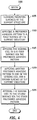
- FIG. 4 is a flowchart of a method for attaching a sensing coil to a support structure in a fiber optic gyroscope in accordance with an exemplary embodiment of the present invention.
- the method begins at step 100.
- the support surfaces 32, 34 ( FIG. 2 ) are cleaned and prepared for applying a pair of preformed adhesive patterns 24, 26 ( FIG. 2 ) at step 105.
- the first preformed adhesive pattern 24 ( FIG. 2 ) is applied to the first support surface 34 ( FIG. 2 ) at step 110.
- the backing on one side of the first preformed adhesive pattern 24 ( FIG. 2 ) is removed to expose the adhesive while the backing on the other side of the first preformed adhesive pattern 24 protects the adhesive during application of the first preformed adhesive pattern 24.
- the remaining backing is removed.
- the first mounting surface 38 ( FIG. 2 ) is affixed to the first support surface 34 ( FIG. 2 ) via the first preformed adhesive pattern 24 ( FIG. 2 ) at step 115.
- the sensing coil 12 Prior to affixing the first mounting surface 38 ( FIG. 2 ) to the first support surface 34 ( FIG.2 ), the sensing coil 12 is axially aligned (e.g., aligned with the axis 13 of the cylindrical wall 18 of the support structure 12 shown in FIG. 2 ).
- the first preformed adhesive pattern 24 FIG.
- the second preformed adhesive pattern 26 ( FIG. 2 ) is preloaded with a predetermined compression (e.g., a 0.005 in. compression depth).
- the second preformed adhesive pattern 26 ( FIG. 2 ) is applied to either the second mounting surface 36 ( FIG. 2 ) or the second support surface 32 ( FIG. 2 ) at step 120. Similar to the first preformed adhesive pattern 24 ( FIG. 2 ), the backing on one side of the second preformed adhesive pattern 26 ( FIG. 2 ) is removed to expose the adhesive while the backing on the other side of the second preformed adhesive pattern 26 protects the adhesive during application of the second preformed adhesive pattern 26. After applying the second preformed adhesive pattern 24 ( FIG. 2 ) to either the second support surface 32 ( FIG. 2 ) or the second mounting surface 36 ( FIG. 2 ), the remaining backing may be removed.
- a predetermined compression e.g., a 0.005 in. compression depth
- the second mounting surface 36 ( FIG. 2 ) is affixed to the second support surface 32 ( FIG. 2 ) via the second preformed adhesive pattern 26 ( FIG. 2 ) at step 125.
- the second preformed adhesive pattern 26 ( FIG. 2 ) may also be preloaded with a predetermined compression.
Landscapes
- Physics & Mathematics (AREA)
- Engineering & Computer Science (AREA)
- Optics & Photonics (AREA)
- Electromagnetism (AREA)
- Power Engineering (AREA)
- General Physics & Mathematics (AREA)
- Radar, Positioning & Navigation (AREA)
- Remote Sensing (AREA)
- Gyroscopes (AREA)
Description
- The present invention generally relates to fiber optic gyroscope systems, and more particularly relates to an attachment system and method for attaching a sensing coil in a fiber optic gyroscope system.
- Gyroscopes have been used to measure rotation rates or changes in angular velocity about an axis. A basic conventional fiber optic gyroscope (FOG) includes a light source, a beam generating device (e.g., a beam-splitter), and a coil of optical fiber coupled to the beam generating device that encircles an area. The beam generating device transmits light beams originating from the light source into the coil of optical fiber, and these light beams propagate in a clockwise (CW) direction and a counter-clockwise (CCW) direction along the core of the optical fiber. The two counter-propagating (e.g., CW and CCW) beams experience different pathlengths while propagating around a rotating path, and the difference between the two pathlengths produces a phase difference between the two counter-propagating beams that is proportional to the rotational rate.
- Many FOGs utilize a glass-based optical fiber to conduct light along a solid core of the fiber over long distances with low loss and distortion. This optical fiber has a glass/silica core surrounded by a polymer jacket, or buffer, and may be wound into a cylindrical structure, such as a coil, and affixed to a coil-supporting structure, such as a cylindrical hub, to form a sensing coil. The hub and fiber optic coil are both substantially cylindrical structures oriented about a center axis, and the hub has a relatively smaller radius than the radius of the fiber optic coil. An adhesive coating between the outer surface of the hub and inner surface of the fiber optic coil may be used affix the fiber optic coil to the hub.
- Because the optical fiber is a composite structure, the glass/silica core and the polymer buffer may each respond differently to a variety of environmental factors and thereby adversely affect the pathlength difference between the two counter-propagating waves. Some of these environmental factors include temperature and mechanical strain that may create a bias between the phases of the two counter-propagating waves such that the output of the sensing coil yields a phase difference between the two counter-propagating waves that is indistinguishable from a rotation-induced phase difference. During operation, a FOG may be placed in an environment having a fluctuating ambient temperature. Temperature variations affect the sensing coil in two ways: first, the sensing coil undergoes mechanical strain as a result of a differential thermal expansion; and second, the optical transmission properties of the optical fiber change with the temperature. A Coefficient of Thermal Expansion (CTE) mismatch between the glass/silica core and the polymer buffer may result in a transverse expansion of the fiber optic coil that is significantly larger than the lengthwise expansion of the fiber optic coil. Because of the non-isotropic structure of the fiber optic coil, the radial expansion of the fiber optic coil, constrained by the glass/silica core of the optical fiber, is significantly smaller than the axial expansion of the fiber optic coil that is dominated by the large CTE of the polymer buffer. Further, the outer diameter of the fiber optic coil generally expands radially away from the center axis of the fiber optic coil while the inner diameter of the fiber optic coil generally expands radially toward the center axis of the fiber optic coil.
- In addition to the expansion of the fiber optic coil, the hub may also expand in response to temperature fluctuations. For example, a hub made from an isotropic material may expand relatively uniformly in both the axial direction and in the radial direction with respect to the center axis. As a result, when a FOG is exposed to a temperature change such that the fiber optic coil and hub both expand, the hub radially expands faster than the fiber optic coil expands, as a whole, and imparts stress on the fiber optic coil. Additionally, the radial expansion of the hub against the opposite expansion direction of the inner diameter of the fiber optic coil may produce significant mechanical interference between theses components resulting in an outward radial pressure exerted at the fiber optic coil interface that induces stresses in the coil structure.
- Employing a compliant adhesive, that distorts to accommodate the outward radial expansion of the hub as well as the inward radial expansion of the inner diameter of the fiber optic coil, may minimize such stresses on the fiber optic coil. When the adhesive is softer than the hub material, the stress induced in the fiber optic coil is generally less than the stress induced by the expanding hub alone. The hydrostatic pressure associated with the axial compression of the adhesive material is relieved through its expansion in lateral directions to the extent allowed by hyper-elastic properties of the adhesive material and by the available free area around the adhesive.
- One method of applying the compliant adhesive is to inject a liquid adhesive, such as a Room Temperature Vulcanizing (RTV) adhesive, through small orifices in the mounting structure (e.g., a coil hub). Typically, the RTV adhesive is a two-part adhesive that is first mixed and then manually injected through the orifices of the bottom surface of the mounting structure via controlled nozzles. Following a curing period, the two-part adhesive is prepared again and then manually injected through the orifices of the top surface of the mounting structure via the controlled nozzles. The sensing coil process completes after another curing period. The combination of the curing periods for the RTV adhesive and the manual effort to inject the RTV adhesive generally consumes a significant amount of process time.
- In addition to the significant process time, the manufacture of conventional coil hubs is generally labor intensive. Small variations in fiber buffer diameter may accumulate and result in a significant variation in coil height from one fiber optic coil to another fiber optic coil, hi general, fiber optic coils are measured after fabrication of the coils, and the coil hubs supporting such fiber optic coils are custom sized to the coils. Typically, the coil hubs are pre-machined and subsequently re-machined after measuring the fiber optic coils. Both the custom machining and the formation of the orifices through the top and bottom surface of the coil hub complicate the manufacturing process of the FOG.
- Accordingly, it is desirable to provide a less complex method for attaching a sensing coil to a support structure in a fiber optic gyroscope while minimizing the coil stress from environmental factors. In addition, it is desirable to provide a sensing coil assembly for a fiber optic gyroscope having minimal construction steps while decreasing the coil stress from environmental factors. Furthermore, other desirable features and characteristics of the present invention will become apparent from the subsequent detailed description of the invention and the appended claims, taken in conjunction with the accompanying drawings and this background of the invention.
-
EP0851213A2 discloses a fiber optic sensor coil with a dummy layer that forms an integral structure with a potted coil.US2004/0041085A1 discloses a buffer layer, for example a potting compound or polymer, that serves as a primary support for an optical fiber winding. - The present invention in its various aspects is as set out in the appended claims. A sensing coil assembly for a fiber optic gyroscope and methods are provided for attaching a sensing coil to a support structure in a fiber optic gyroscope. In an exemplary embodiment, the method comprises affixing a first support surface of the support structure to a first mounting surface of the sensing coil via a first preformed adhesive, and affixing a second support surface of the support structure to a second mounting surface of the sensing coil via a second preformed adhesive.
- In another exemplary embodiment, the method comprises applying a first preformed adhesive pattern to a first surface of the support structure, affixing the sensing coil to the first surface of the support structure via the first preformed adhesive pattern, applying a second preformed adhesive pattern to one of the sensing coil and a second surface of the support structure, and affixing the sensing coil to the second surface of the support structure via the second preformed adhesive pattern.
- In yet another exemplary embodiment, the sensing coil assembly comprises a support structure having first and second support surfaces and having a substantially cylindrical hub coupled between the first and second opposing surfaces, an optical fiber coil surrounding at least a portion of the substantially cylindrical hub, and first and second preformed adhesive patterns affixing the optical fiber coil to the first and second opposing surfaces. The first support surface opposes the second support surface.
- The present invention will hereinafter be described in conjunction with the following drawing figures, wherein like numerals denote like elements, and
-
FIG. 1 is a perspective view of a sensing coil assembly for a fiber optic gyroscope in accordance with an exemplary embodiment of the present invention; -
FIG. 2 is a cross-sectional view of the sensing coil assembly shown inFIG. 1 ; -
FIG. 3 is an exploded view of the sensing coil assembly shown inFIG. 1 ; -
FIG. 4 is a flowchart of a method for attaching a sensing coil to a support structure in a fiber optic gyroscope in accordance with an exemplary embodiment of the present invention. - The following detailed description of the invention is merely exemplary in nature and is not intended to limit the invention or the application and uses of the invention. Furthermore, there is no intention to be bound by any theory presented in the preceding background of the invention or the following detailed description of the invention.
- A sensing coil assembly and method for attaching a sensing coil to a support structure in a fiber optic gyroscope (FOG) are provided. In one exemplary embodiment, the sensing coil assembly comprises a support structure having first and second support surfaces and having a substantially cylindrical hub coupled between the first and second opposing surfaces, an optical fiber coil surrounding at least a portion of the substantially cylindrical hub, and first and second preformed adhesive patterns affixing the optical fiber coil to the first and second opposing surfaces. The first support surface opposes the second support surface.
- Referring now to the drawings,
FIG. 1 is a perspective view of asensing coil assembly 10 for a FOG in accordance with an exemplary embodiment of the present invention.FIG. 2 is a cross-sectional view of the sensing coil assembly shown inFIG. 1 .FIG. 3 is an exploded view of thesensing coil assembly 10 shown inFIG. 1 . Thesensing coil assembly 10 comprises asupport structure 30, such as a hub, asensing coil 12 surrounding at least a portion of thesupport structure 30, and apreformed adhesive sensing coil 12 to thesupport structure 30. Thesupport structure 30 comprises abottom flange 16, atop flange 14, and a substantiallycylindrical wall 18 coupling thebottom flange 16 to thetop flange 14. In an exemplary embodiment, thebottom flange 16 provides afirst support surface 34, and thetop flange 14 provides asecond support surface 32. The support surfaces 34, 32 both couple with thesensing coil 12 via thepreformed adhesive sensing coil assembly 10, both thesensing coil 12 and thesupport structure 30 are oriented about anaxis 13 of thecylindrical wall 18. - The
support structure 30 may be made from a variety of materials. Exemplary hub materials include, but are not limited to: metal alloys, such as titanium; sintered metal composites made using powder metallurgy, such as copper tungsten or copper molybdenum; composite materials, such as filament wound fiber glass/epoxy, fiber glass/epoxy or aramid/epoxy; metal matrix composites, such as metal reinforced with ceramics such as boron, silicon, carbide, and graphite; ceramics; and, a composite made from any of the aforementioned materials. Although each of these materials may exhibit different thermal expansion, the selection of the hub material is not critical to minimizing coil stress from environmental factors, such as temperature and mechanical stress. The selection of hub material may be based in part on a particular application of the FOG and may influence the choice of both the adhesive andsupport structure 30 to optimize the particular application. - The
sensing coil 12 comprises a wound optical fiber made from a glass medium. The optical fiber has an inner glass core and an outer glass shell, and the inner glass core and the outer glass shell have different optical indices of refraction. A polymer coating, or jacket, covers the outer glass to protect the surface of the outer glass from defects. In general, the optical fiber is specifically wound onto a bobbin, adhered, and cured to form thesensing coil 12 although other methods may be used to produce thesensing coil 12 from the optical fiber. Thesensing coil 12 is substantially cylindrical with a relatively thick cylindrical wall of optical fiber and has first and second mounting surfaces 38, 36 for coupling to the first and second support surfaces 34, 32, respectively, via the preformed adhesive 24, 26. For example, thesensing coil 12 has a first mountingsurface 38 for coupling with thefirst support surface 34 and has a second mountingsurface 36 for coupling with thesecond support surface 32. - In an exemplary embodiment, the preformed adhesive 24, 26 comprises a first
adhesive pattern 24 that affixes the first mountingsurface 38 to thefirst support surface 34, and a secondadhesive pattern 26 that affixes the second mountingsurface 36 of thesensing coil 12 to thesecond support surface 32. Each of theadhesive patterns adhesive dots adhesive patterns adhesive patterns adhesive patterns coil 12 and thesupport structure 30. For example, each of theadhesive patterns support structure 30 and thesensing coil 12. - In this exemplary embodiment, the first preformed
adhesive pattern 24 is placed between thefirst support surface 34 and the first mountingsurface 38, and the second preformedadhesive pattern 24 is placed between thesecond support surface 32 and the second mountingsurface 36. At least one of theadhesive patterns sensing coil 12 to thesupport structure 30. Theadhesive patterns sensing coil 12 during expansion and contraction, such as from temperature fluctuations, and thereby minimizes distortion of thesensing coil 12. Additionally, using preformed and substantially non-liquid adhesive patterns significantly reduces process time for attaching thesensing coil 12 to thesupport structure 30. -
FIG. 4 is a flowchart of a method for attaching a sensing coil to a support structure in a fiber optic gyroscope in accordance with an exemplary embodiment of the present invention. The method begins atstep 100. The support surfaces 32, 34 (FIG. 2 ) are cleaned and prepared for applying a pair of preformedadhesive patterns 24, 26 (FIG. 2 ) atstep 105. The first preformed adhesive pattern 24 (FIG. 2 ) is applied to the first support surface 34 (FIG. 2 ) atstep 110. The backing on one side of the first preformed adhesive pattern 24 (FIG. 2 ) is removed to expose the adhesive while the backing on the other side of the first preformedadhesive pattern 24 protects the adhesive during application of the first preformedadhesive pattern 24. After applying the first preformed adhesive pattern 24 (FIG. 2 ) to the first support surface 34 (FIG. 2 ), the remaining backing is removed. The first mounting surface 38 (FIG. 2 ) is affixed to the first support surface 34 (FIG. 2 ) via the first preformed adhesive pattern 24 (FIG. 2 ) atstep 115. Prior to affixing the first mounting surface 38 (FIG. 2 ) to the first support surface 34 (FIG.2 ), thesensing coil 12 is axially aligned (e.g., aligned with theaxis 13 of thecylindrical wall 18 of thesupport structure 12 shown inFIG. 2 ). Upon affixing the first mounting surface 38 (FIG. 2 ) to the first support surface 34 (FIG. 2 ), the first preformed adhesive pattern 24 (FIG. 2 ) is preloaded with a predetermined compression (e.g., a 0.005 in. compression depth). The second preformed adhesive pattern 26 (FIG. 2 ) is applied to either the second mounting surface 36 (FIG. 2 ) or the second support surface 32 (FIG. 2 ) atstep 120. Similar to the first preformed adhesive pattern 24 (FIG. 2 ), the backing on one side of the second preformed adhesive pattern 26 (FIG. 2 ) is removed to expose the adhesive while the backing on the other side of the second preformedadhesive pattern 26 protects the adhesive during application of the second preformedadhesive pattern 26. After applying the second preformed adhesive pattern 24 (FIG. 2 ) to either the second support surface 32 (FIG. 2 ) or the second mounting surface 36 (FIG. 2 ), the remaining backing may be removed. The second mounting surface 36 (FIG. 2 ) is affixed to the second support surface 32 (FIG. 2 ) via the second preformed adhesive pattern 26 (FIG. 2 ) atstep 125. Upon affixing the second mounting surface 36 (FIG. 2 ) to the second support surface 32 (FIG. 2 ), the second preformed adhesive pattern 26 (FIG. 2 ) may also be preloaded with a predetermined compression. - While at least one exemplary embodiment has been presented in the foregoing detailed description of the invention, it should be appreciated that a vast number of variations exist. It should also be appreciated that the exemplary embodiment or exemplary embodiments are only examples, and are not intended to limit the scope, applicability, or configuration of the invention in any way. Rather, the foregoing detailed description will provide those skilled in the art with a convenient road map for implementing an exemplary embodiment of the invention. It being understood that various changes may be made in the function and arrangement of elements described in an exemplary embodiment without departing from the scope of the invention as set forth in the appended claims.
Claims (11)
- A method for attaching a sensing coil (12) to a support structure (30) in a fiber optic gyroscope, the method comprising the steps of:affixing (115) a first support surface (34) of the support structure (30) to a first mounting surface (38) of the sensing coil (12) with a first preformed adhesive (24), wherein the first preformed adhesive is a double-sided adhesive and precut from a layer of pressure sensitive material; andaffixing (125) a second support surface (32) of the support structure (30) to a second mounting surface (36) of the sensing coil (12) with a second preformed adhesive (26), wherein the second preformed adhesive is a double-sided adhesive and precut from a layer of pressure sensitive material.
- A method according to claim 1, wherein said step of affixing the first support surface (34) comprises compressing the first preformed adhesive (24) with a predetermined preload.
- A method according to claim 1, wherein said step of affixing the second support surface (32) comprises compressing the second preformed adhesive (26) with a predetermined preload.
- The method according to claims 2-3, wherein said first and second preformed adhesives each comprises a visco-elastic dampening polymer.
- A method according to claim 1, wherein said step of affixing the first support surface (34) comprises:placing (110) the first preformed adhesive (24) on the first support surface (34); andmounting the first mounting surface (38) onto the first support surface (34).
- A method according to claim 5, wherein said step of affixing the second support surface comprises:placing (120) the second preformed adhesive (26) on the second mounting surface (36); andmounting the second support surface (32) onto the second mounting surface (36).
- A sensing coil assembly (10) for a fiber optic gyroscope, the sensing coil assembly (10) comprising:a support structure (30) comprising:first and second support surfaces (34, 32), said first support surface (34) opposing said second support surface (32); anda substantially cylindrical hub (18) coupled between said first and second opposing surfaces (34, 32);an optical fiber coil (12) surrounding at least a portion of said substantially cylindrical hub (18); anda first preformed adhesive pattern (24) affixing said optical fiber coil (12) to said first opposing surface (34), wherein the first preformed adhesive pattern (24) is a double-sided adhesive and precut from a layer of pressure sensitive material; anda second preformed adhesive pattern (26) affixing said optical fiber coil (12) to said second opposing surface (32), wherein the second preformed adhesive pattern (26) is a double-sided adhesive and precut from a layer of pressure sensitive material.
- The sensing coil assembly (10) according to claim 7, wherein said optical fiber coil (12) comprises:a first mounting surface (38); anda second mounting surface (36) opposing said first mounting surface (38);wherein said first preformed adhesive pattern (24) affixes said first mounting surface (38) to said first support surface (34); andwherein said second preformed adhesive pattern (26) affixes said second mounting surface (36) to said second support surface (32).
- The sensing coil assembly (10) according to claim 7, wherein said first and second preformed adhesive patterns (24, 26) each comprises a uniform array of adhesive dots (20, 22).
- The sensing coil assembly (10) according to claim 7, wherein said first and second preformed adhesive patterns (24, 26) each comprises a visco-elastic dampening polymer; and
wherein at least one of said first and second preformed adhesive patterns (24, 26) is preloaded to a predetermined compression. - The sensing coil assembly (10) according to claim 10, wherein when the sensing coil assembly (10) encounters a vibration said visco-elastic dampening polymer is configured to attenuate said vibration.
Applications Claiming Priority (2)
| Application Number | Priority Date | Filing Date | Title |
|---|---|---|---|
| US11/139,348 US7369245B2 (en) | 2005-05-27 | 2005-05-27 | Sensing coil assembly and method for attaching a sensing coil in a fiber optic gyroscope |
| PCT/US2006/019992 WO2006130396A1 (en) | 2005-05-27 | 2006-05-23 | Sensing coil assembly and method for attaching a sensing coil in a fiber optic gyroscope |
Publications (2)
| Publication Number | Publication Date |
|---|---|
| EP1883785A1 EP1883785A1 (en) | 2008-02-06 |
| EP1883785B1 true EP1883785B1 (en) | 2018-10-03 |
Family
ID=36954468
Family Applications (1)
| Application Number | Title | Priority Date | Filing Date |
|---|---|---|---|
| EP06771006.1A Ceased EP1883785B1 (en) | 2005-05-27 | 2006-05-23 | Sensing coil assembly and method for attaching a sensing coil in a fiber optic gyroscope |
Country Status (4)
| Country | Link |
|---|---|
| US (1) | US7369245B2 (en) |
| EP (1) | EP1883785B1 (en) |
| JP (1) | JP2008542718A (en) |
| WO (1) | WO2006130396A1 (en) |
Families Citing this family (3)
| Publication number | Priority date | Publication date | Assignee | Title |
|---|---|---|---|---|
| ATE428421T1 (en) | 2004-09-17 | 2009-05-15 | Eisai R&D Man Co Ltd | MEDICAL COMPOSITION WITH IMPROVED STABILITY AND REDUCED GELING PROPERTIES |
| CN102967302B (en) * | 2012-11-16 | 2015-04-29 | 中国船舶重工集团公司第七一七研究所 | Framework for optical fiber gyroscope and manufacturing method thereof as well as method for packaging optical fiber ring |
| CN109141480A (en) * | 2018-10-31 | 2019-01-04 | 中国船舶重工集团公司第七0七研究所 | A kind of optical fibre gyro ring bonding failure analysis methods |
Family Cites Families (20)
| Publication number | Priority date | Publication date | Assignee | Title |
|---|---|---|---|---|
| JPS62126602A (en) * | 1985-11-28 | 1987-06-08 | Toshiba Corp | Coil of electric apparatus and manufacture thereof |
| JPS62183875A (en) * | 1985-12-27 | 1987-08-12 | ガイムプラスト ペ−タ− ムント ゲゼルシヤフト ミツト ベシユレンクテル ハフツング ウント コムパニ− コマンデイツト ゲゼルシヤフト | Method and device for bonding part of film holding frame by adhesive |
| US4856900A (en) * | 1987-06-03 | 1989-08-15 | Litton Systems, Inc. | Quadrupole-wound fiber optic sensing coil and method of manufacture thereof |
| US5546482A (en) * | 1993-04-19 | 1996-08-13 | Litton Systems, Inc. | Potted fiber optic gyro sensor coil for stringent vibration and thermal enviroments |
| JPH0728004A (en) * | 1993-07-08 | 1995-01-31 | Sumitomo Electric Ind Ltd | Optical fiber phase modulator |
| US5624521A (en) * | 1993-09-21 | 1997-04-29 | Hed; P. Paul | Method of holding optical elements without deformation during their fabrication |
| JPH07209003A (en) * | 1994-01-26 | 1995-08-11 | Japan Aviation Electron Ind Ltd | Optical fiber gyro and method of manufacturing the same |
| US5545892A (en) * | 1994-09-01 | 1996-08-13 | Litton Systems, Inc. | Gyro sensor coil with low-friction hub interface |
| US5486922A (en) * | 1994-12-20 | 1996-01-23 | Litton Systems, Inc. | Sensor coil with thermomechanically-matched spool for fiber optic gyroscope |
| IT248428Y1 (en) * | 1996-03-01 | 2003-01-28 | Gore W L & Ass Srl | FOOTWEAR WITH BREATHABLE ELEMENT INSERTED IN THE UPPER |
| US5855353A (en) * | 1996-05-31 | 1999-01-05 | Owens Corning Fiberglas Technology, Inc. | Vibration damping system |
| US5767509A (en) | 1996-12-24 | 1998-06-16 | Litton Systems, Inc. | Fiber optic sensor coil including buffer regions |
| JP4056637B2 (en) * | 1998-09-11 | 2008-03-05 | ペンタックス株式会社 | Optical element bonding device |
| JP2002082229A (en) * | 2000-07-07 | 2002-03-22 | Sumitomo Electric Ind Ltd | Optical component manufacturing method |
| US6496263B1 (en) * | 2000-07-27 | 2002-12-17 | Litton Systems, Inc. | System and method for providing an improved IFOG hub to coil thermal and mechanical slip interface |
| JP2002286451A (en) * | 2001-03-27 | 2002-10-03 | Tokimec Inc | Vibration-proof buffer device for gyrocompass |
| JP2003203813A (en) * | 2001-08-29 | 2003-07-18 | Matsushita Electric Ind Co Ltd | Magnetic element, method of manufacturing the same, and power supply module having the same |
| JP2003185848A (en) * | 2001-12-18 | 2003-07-03 | Tomoegawa Paper Co Ltd | Optical fiber excess length processing sheet and optical fiber excess length processing method |
| US20030173024A1 (en) * | 2002-03-15 | 2003-09-18 | Nordson Corporation | Method of securing elastic strands to flat substrates and products produced by the method |
| US6898364B2 (en) * | 2002-08-27 | 2005-05-24 | Northrop Grumman Corporation | Buffer layer promotion of decrease of one or more strain gradients in optical fiber winding |
-
2005
- 2005-05-27 US US11/139,348 patent/US7369245B2/en not_active Expired - Lifetime
-
2006
- 2006-05-23 EP EP06771006.1A patent/EP1883785B1/en not_active Ceased
- 2006-05-23 WO PCT/US2006/019992 patent/WO2006130396A1/en not_active Ceased
- 2006-05-23 JP JP2008513638A patent/JP2008542718A/en active Pending
Non-Patent Citations (1)
| Title |
|---|
| None * |
Also Published As
| Publication number | Publication date |
|---|---|
| EP1883785A1 (en) | 2008-02-06 |
| US20060268278A1 (en) | 2006-11-30 |
| US7369245B2 (en) | 2008-05-06 |
| WO2006130396A1 (en) | 2006-12-07 |
| JP2008542718A (en) | 2008-11-27 |
Similar Documents
| Publication | Publication Date | Title |
|---|---|---|
| EP0694761B1 (en) | Fiber optic gyroscope with hard potted sensor coil | |
| CA2157459C (en) | Slip interface for mounting gyro sensor coil | |
| US5486922A (en) | Sensor coil with thermomechanically-matched spool for fiber optic gyroscope | |
| US5818590A (en) | Flange-supported sensor coil for a fiber optic gyroscope | |
| US7369245B2 (en) | Sensing coil assembly and method for attaching a sensing coil in a fiber optic gyroscope | |
| EP1163491B1 (en) | Adhesive system for a fiber optic gyroscope sensing coil | |
| US7369247B2 (en) | Sensing coil assembly and method for attaching a sensing coil in a fiber optic gyroscope | |
| EP1651926B1 (en) | Polymeric material with compressible voids to allow the polymeric material to absorb applied force and decrease reaction force to one or more sensor fibers | |
| EP1222440B1 (en) | Fiber optic gyroscope | |
| US6040908A (en) | Method for stress tuning fiber optic sensor coils | |
| US6054068A (en) | Potting compound for fabrication of fiber optic gyro sensor coil and method for fabricating sensor coil | |
| US7295323B2 (en) | Adhesive system and method for forming a fiber optic gyroscope sensing coil | |
| US5767970A (en) | Bonded fiber optic gyro sensor coil including voids | |
| CN211926875U (en) | Optical fiber gyroscope supporting framework and optical fiber gyroscope | |
| JP2708370B2 (en) | Pot-shaped optical fiber gyro sensor coil | |
| EP3736533B1 (en) | Fiber-optic gyroscope (fog) assembly | |
| CN109186583B (en) | Tail fiber gluing process method for improving ring performance of fiber-optic gyroscope | |
| CA2493810A1 (en) | Fibre gyroscope with buffer layers and potting material for the fibre coil | |
| JPH0861962A (en) | Sensor coil for low-bias optical fiber gyroscope | |
| CA2117416A1 (en) | Sensor coil for low bias fiber optic gyroscope |
Legal Events
| Date | Code | Title | Description |
|---|---|---|---|
| PUAI | Public reference made under article 153(3) epc to a published international application that has entered the european phase |
Free format text: ORIGINAL CODE: 0009012 |
|
| 17P | Request for examination filed |
Effective date: 20071121 |
|
| AK | Designated contracting states |
Kind code of ref document: A1 Designated state(s): DE FR |
|
| DAX | Request for extension of the european patent (deleted) | ||
| RBV | Designated contracting states (corrected) |
Designated state(s): DE FR |
|
| 17Q | First examination report despatched |
Effective date: 20150511 |
|
| RAP1 | Party data changed (applicant data changed or rights of an application transferred) |
Owner name: HONEYWELL INTERNATIONAL INC. |
|
| GRAP | Despatch of communication of intention to grant a patent |
Free format text: ORIGINAL CODE: EPIDOSNIGR1 |
|
| INTG | Intention to grant announced |
Effective date: 20180418 |
|
| GRAJ | Information related to disapproval of communication of intention to grant by the applicant or resumption of examination proceedings by the epo deleted |
Free format text: ORIGINAL CODE: EPIDOSDIGR1 |
|
| GRAS | Grant fee paid |
Free format text: ORIGINAL CODE: EPIDOSNIGR3 |
|
| GRAJ | Information related to disapproval of communication of intention to grant by the applicant or resumption of examination proceedings by the epo deleted |
Free format text: ORIGINAL CODE: EPIDOSDIGR1 |
|
| GRAP | Despatch of communication of intention to grant a patent |
Free format text: ORIGINAL CODE: EPIDOSNIGR1 |
|
| GRAJ | Information related to disapproval of communication of intention to grant by the applicant or resumption of examination proceedings by the epo deleted |
Free format text: ORIGINAL CODE: EPIDOSDIGR1 |
|
| GRAS | Grant fee paid |
Free format text: ORIGINAL CODE: EPIDOSNIGR3 |
|
| GRAS | Grant fee paid |
Free format text: ORIGINAL CODE: EPIDOSNIGR3 |
|
| GRAP | Despatch of communication of intention to grant a patent |
Free format text: ORIGINAL CODE: EPIDOSNIGR1 |
|
| INTC | Intention to grant announced (deleted) | ||
| GRAA | (expected) grant |
Free format text: ORIGINAL CODE: 0009210 |
|
| INTG | Intention to grant announced |
Effective date: 20180816 |
|
| AK | Designated contracting states |
Kind code of ref document: B1 Designated state(s): DE FR |
|
| REG | Reference to a national code |
Ref country code: DE Ref legal event code: R096 Ref document number: 602006056494 Country of ref document: DE |
|
| REG | Reference to a national code |
Ref country code: DE Ref legal event code: R097 Ref document number: 602006056494 Country of ref document: DE |
|
| PLBE | No opposition filed within time limit |
Free format text: ORIGINAL CODE: 0009261 |
|
| STAA | Information on the status of an ep patent application or granted ep patent |
Free format text: STATUS: NO OPPOSITION FILED WITHIN TIME LIMIT |
|
| 26N | No opposition filed |
Effective date: 20190704 |
|
| REG | Reference to a national code |
Ref country code: DE Ref legal event code: R119 Ref document number: 602006056494 Country of ref document: DE |
|
| PG25 | Lapsed in a contracting state [announced via postgrant information from national office to epo] |
Ref country code: DE Free format text: LAPSE BECAUSE OF NON-PAYMENT OF DUE FEES Effective date: 20191203 |
|
| PGFP | Annual fee paid to national office [announced via postgrant information from national office to epo] |
Ref country code: FR Payment date: 20200527 Year of fee payment: 15 |
|
| PG25 | Lapsed in a contracting state [announced via postgrant information from national office to epo] |
Ref country code: FR Free format text: LAPSE BECAUSE OF NON-PAYMENT OF DUE FEES Effective date: 20210531 |
|
| P01 | Opt-out of the competence of the unified patent court (upc) registered |
Effective date: 20230525 |