EP1883269B1 - Reproducing apparatus and method for reproducing audio therefor - Google Patents
Reproducing apparatus and method for reproducing audio therefor Download PDFInfo
- Publication number
- EP1883269B1 EP1883269B1 EP07102464.0A EP07102464A EP1883269B1 EP 1883269 B1 EP1883269 B1 EP 1883269B1 EP 07102464 A EP07102464 A EP 07102464A EP 1883269 B1 EP1883269 B1 EP 1883269B1
- Authority
- EP
- European Patent Office
- Prior art keywords
- casing
- reproducing apparatus
- output unit
- audio
- internal
- Prior art date
- Legal status (The legal status is an assumption and is not a legal conclusion. Google has not performed a legal analysis and makes no representation as to the accuracy of the status listed.)
- Active
Links
Images



Classifications
-
- G—PHYSICS
- G11—INFORMATION STORAGE
- G11B—INFORMATION STORAGE BASED ON RELATIVE MOVEMENT BETWEEN RECORD CARRIER AND TRANSDUCER
- G11B20/00—Signal processing not specific to the method of recording or reproducing; Circuits therefor
- G11B20/10—Digital recording or reproducing
-
- H—ELECTRICITY
- H04—ELECTRIC COMMUNICATION TECHNIQUE
- H04R—LOUDSPEAKERS, MICROPHONES, GRAMOPHONE PICK-UPS OR LIKE ACOUSTIC ELECTROMECHANICAL TRANSDUCERS; ELECTRIC HEARING AIDS; PUBLIC ADDRESS SYSTEMS
- H04R3/00—Circuits for transducers
- H04R3/12—Circuits for transducers for distributing signals to two or more loudspeakers
-
- G—PHYSICS
- G06—COMPUTING OR CALCULATING; COUNTING
- G06F—ELECTRIC DIGITAL DATA PROCESSING
- G06F1/00—Details not covered by groups G06F3/00 - G06F13/00 and G06F21/00
- G06F1/16—Constructional details or arrangements
- G06F1/1613—Constructional details or arrangements for portable computers
- G06F1/1615—Constructional details or arrangements for portable computers with several enclosures having relative motions, each enclosure supporting at least one I/O or computing function
- G06F1/1616—Constructional details or arrangements for portable computers with several enclosures having relative motions, each enclosure supporting at least one I/O or computing function with folding flat displays, e.g. laptop computers or notebooks having a clamshell configuration, with body parts pivoting to an open position around an axis parallel to the plane they define in closed position
-
- G—PHYSICS
- G06—COMPUTING OR CALCULATING; COUNTING
- G06F—ELECTRIC DIGITAL DATA PROCESSING
- G06F1/00—Details not covered by groups G06F3/00 - G06F13/00 and G06F21/00
- G06F1/16—Constructional details or arrangements
- G06F1/1613—Constructional details or arrangements for portable computers
- G06F1/1615—Constructional details or arrangements for portable computers with several enclosures having relative motions, each enclosure supporting at least one I/O or computing function
- G06F1/1624—Constructional details or arrangements for portable computers with several enclosures having relative motions, each enclosure supporting at least one I/O or computing function with sliding enclosures, e.g. sliding keyboard or display
-
- G—PHYSICS
- G06—COMPUTING OR CALCULATING; COUNTING
- G06F—ELECTRIC DIGITAL DATA PROCESSING
- G06F1/00—Details not covered by groups G06F3/00 - G06F13/00 and G06F21/00
- G06F1/16—Constructional details or arrangements
- G06F1/1613—Constructional details or arrangements for portable computers
- G06F1/1626—Constructional details or arrangements for portable computers with a single-body enclosure integrating a flat display, e.g. Personal Digital Assistants [PDAs]
-
- G—PHYSICS
- G06—COMPUTING OR CALCULATING; COUNTING
- G06F—ELECTRIC DIGITAL DATA PROCESSING
- G06F1/00—Details not covered by groups G06F3/00 - G06F13/00 and G06F21/00
- G06F1/16—Constructional details or arrangements
- G06F1/1613—Constructional details or arrangements for portable computers
- G06F1/1633—Constructional details or arrangements of portable computers not specific to the type of enclosures covered by groups G06F1/1615 - G06F1/1626
- G06F1/1675—Miscellaneous details related to the relative movement between the different enclosures or enclosure parts
- G06F1/1677—Miscellaneous details related to the relative movement between the different enclosures or enclosure parts for detecting open or closed state or particular intermediate positions assumed by movable parts of the enclosure, e.g. detection of display lid position with respect to main body in a laptop, detection of opening of the cover of battery compartment
-
- G—PHYSICS
- G06—COMPUTING OR CALCULATING; COUNTING
- G06F—ELECTRIC DIGITAL DATA PROCESSING
- G06F1/00—Details not covered by groups G06F3/00 - G06F13/00 and G06F21/00
- G06F1/16—Constructional details or arrangements
- G06F1/1613—Constructional details or arrangements for portable computers
- G06F1/1633—Constructional details or arrangements of portable computers not specific to the type of enclosures covered by groups G06F1/1615 - G06F1/1626
- G06F1/1684—Constructional details or arrangements related to integrated I/O peripherals not covered by groups G06F1/1635 - G06F1/1675
- G06F1/1688—Constructional details or arrangements related to integrated I/O peripherals not covered by groups G06F1/1635 - G06F1/1675 the I/O peripheral being integrated loudspeakers
-
- G—PHYSICS
- G11—INFORMATION STORAGE
- G11B—INFORMATION STORAGE BASED ON RELATIVE MOVEMENT BETWEEN RECORD CARRIER AND TRANSDUCER
- G11B19/00—Driving, starting, stopping record carriers not specifically of filamentary or web form, or of supports therefor; Control thereof; Control of operating function ; Driving both disc and head
- G11B19/02—Control of operating function, e.g. switching from recording to reproducing
-
- G—PHYSICS
- G11—INFORMATION STORAGE
- G11B—INFORMATION STORAGE BASED ON RELATIVE MOVEMENT BETWEEN RECORD CARRIER AND TRANSDUCER
- G11B33/00—Constructional parts, details or accessories not provided for in the other groups of this subclass
- G11B33/02—Cabinets; Cases; Stands; Disposition of apparatus therein or thereon
-
- H—ELECTRICITY
- H04—ELECTRIC COMMUNICATION TECHNIQUE
- H04M—TELEPHONIC COMMUNICATION
- H04M1/00—Substation equipment, e.g. for use by subscribers
- H04M1/02—Constructional features of telephone sets
- H04M1/0202—Portable telephone sets, e.g. cordless phones, mobile phones or bar type handsets
- H04M1/0206—Portable telephones comprising a plurality of mechanically joined movable body parts, e.g. hinged housings
- H04M1/0241—Portable telephones comprising a plurality of mechanically joined movable body parts, e.g. hinged housings using relative motion of the body parts to change the operational status of the telephone set, e.g. switching on/off, answering incoming call
- H04M1/0245—Portable telephones comprising a plurality of mechanically joined movable body parts, e.g. hinged housings using relative motion of the body parts to change the operational status of the telephone set, e.g. switching on/off, answering incoming call using open/close detection
-
- H—ELECTRICITY
- H04—ELECTRIC COMMUNICATION TECHNIQUE
- H04M—TELEPHONIC COMMUNICATION
- H04M1/00—Substation equipment, e.g. for use by subscribers
- H04M1/72—Mobile telephones; Cordless telephones, i.e. devices for establishing wireless links to base stations without route selection
- H04M1/724—User interfaces specially adapted for cordless or mobile telephones
- H04M1/72403—User interfaces specially adapted for cordless or mobile telephones with means for local support of applications that increase the functionality
- H04M1/72442—User interfaces specially adapted for cordless or mobile telephones with means for local support of applications that increase the functionality for playing music files
-
- H—ELECTRICITY
- H04—ELECTRIC COMMUNICATION TECHNIQUE
- H04R—LOUDSPEAKERS, MICROPHONES, GRAMOPHONE PICK-UPS OR LIKE ACOUSTIC ELECTROMECHANICAL TRANSDUCERS; ELECTRIC HEARING AIDS; PUBLIC ADDRESS SYSTEMS
- H04R2420/00—Details of connection covered by H04R, not provided for in its groups
- H04R2420/01—Input selection or mixing for amplifiers or loudspeakers
-
- H—ELECTRICITY
- H04—ELECTRIC COMMUNICATION TECHNIQUE
- H04R—LOUDSPEAKERS, MICROPHONES, GRAMOPHONE PICK-UPS OR LIKE ACOUSTIC ELECTROMECHANICAL TRANSDUCERS; ELECTRIC HEARING AIDS; PUBLIC ADDRESS SYSTEMS
- H04R2420/00—Details of connection covered by H04R, not provided for in its groups
- H04R2420/03—Connection circuits to selectively connect loudspeakers or headphones to amplifiers
-
- H—ELECTRICITY
- H04—ELECTRIC COMMUNICATION TECHNIQUE
- H04R—LOUDSPEAKERS, MICROPHONES, GRAMOPHONE PICK-UPS OR LIKE ACOUSTIC ELECTROMECHANICAL TRANSDUCERS; ELECTRIC HEARING AIDS; PUBLIC ADDRESS SYSTEMS
- H04R2499/00—Aspects covered by H04R or H04S not otherwise provided for in their subgroups
- H04R2499/10—General applications
- H04R2499/11—Transducers incorporated or for use in hand-held devices, e.g. mobile phones, PDA's, camera's
-
- H—ELECTRICITY
- H04—ELECTRIC COMMUNICATION TECHNIQUE
- H04R—LOUDSPEAKERS, MICROPHONES, GRAMOPHONE PICK-UPS OR LIKE ACOUSTIC ELECTROMECHANICAL TRANSDUCERS; ELECTRIC HEARING AIDS; PUBLIC ADDRESS SYSTEMS
- H04R5/00—Stereophonic arrangements
- H04R5/04—Circuit arrangements, e.g. for selective connection of amplifier inputs/outputs to loudspeakers, for loudspeaker detection, or for adaptation of settings to personal preferences or hearing impairments
Definitions
- aspects of the present invention relate to a reproducing apparatus and a method thereof, and more particularly, to a reproducing apparatus capable of reproducing audio and/or video files and a method thereof.
- the appearance of the electronic device casings can be transformed by the user, such as with a folder type mobile telephone, which can be folded while carrying the phone, and which can be unfolded during operation.
- the user may also be inconvenienced when using multi-functional electronic device casings, because the user has to set options related to the function of the device casings. Therefore, methods for improving convenience and simplicity in setting those options related to the function of the device casings are required.
- US 2003/008689 A1 discloses a wireless portable terminal device which has a first casing and a second casing. Those two casings are coupled to each other, but the main display may be arranged in a folded and an unfolded state. However, this reference does not disclose an internal output unit comprising a speaker that is exposed only in case the second casing is open.
- US 2006/060762 A1 discloses a folding-type mobile telephone. An angle of folding is limited to define a closed and an open position.
- US 2005/083351 A1 discloses a device with magnetic detecting units, wherein the first magnetic detecting unit can detect magnetism of a magnetic circuit of a first speaker and wherein the second magnetic detection unit can detect magnetism of a magnet circuit of a further speaker.
- JP 2002-368860 A discloses a mobile phone with a first housing and a second housing. The first housing is slidably mounted to the front surface of a case of the first housing. A speaker part is arranged below the second housing in the closed state. This reference does not disclose any inclination of a casing or that in the unfolded state of the corresponding casing the internal output unit is visible and usable with its speaker.
- US 2006/073859 A1 discloses a sliding mechanism to couple a cover and a body.
- the cover is slidably disposed above the body and is movable between an open and a closed position.
- aspects of embodiments of the present invention solve at least the above problems and/or disadvantages and provide at least the advantages described below. Accordingly, aspects of embodiments of the present invention provide a reproducing apparatus according to claim 1 and a method according to claim 11, for converting output mode of an audio and/or a video on the basis of the position or movements of a device casing.
- the detector is disposed at the first casing to detect movements of the second casing relative to the first casing based on whether or not an emission is detected from electronic parts of the second casing.
- the emission from the electronic parts comprises one of electric components, magnetic components, electromagnetic components, and light components.
- the detector detects movements of the second casing relative to the first casing based on whether a magnetic field, emitted by a magnet of the internal speaker provided in the second casing, is detected.
- the detector comprises one of a vertical magnetic sensor to sense the magnetic field through a sensor surface vertical to the magnetic field, and a horizontal magnetic sensor sense the magnetic field through a sensor surface horizontal to the magnetic field.
- one side of the second casing is a side from which the reproduced audio is outputted through the internal output unit.
- detecting the position of the second casing relative to the first casing comprises detecting movements of the second casing relative to the first casing based on whether an emission from electric parts of the second casing is detected.
- the emission from the electric parts comprises any one of electric components, magnetic components, electromagnetic components, and light components.
- detecting the position of the second casing relative to the first casing comprises detecting movements of the second casing relative to the first casing based on whether a magnetic field emitted from a magnet of a speaker in the second casing is detected.
- controlling the output of the reproduced audio comprises outputting the reproduced audio via the internal output unit when the second casing is moved from a position where the second casing covers the first casing to a position where the second casing uncovers the first casing.
- FIG. 1A and FIG. 1B are perspective views of an appearance of an audio reproducing apparatus according to an exemplary embodiment of the present invention.
- the audio reproducing apparatus 100 may have a structure of a main casing 100-1 combined with an auxiliary casing 100-2.
- the auxiliary casing 100-2 has a predetermined angle of inclination after being slidably guided along a lower surface of the main casing 100-1.
- Other examples not falling within the scope of the invention may use different configurations, such as a hinge attaching the auxiliary casing 100-2 to the main casing 100-1.
- a display and a control button are located on the outside of the main casing 100-1, and a detecting element (not illustrated), detecting movements of the auxiliary casing 100-2, is located inside the main casing 100-1. Such detecting element will be described later.
- An internal speaker (not illustrated) and a battery (not illustrated) are provided inside the auxiliary casing 100-2.
- an audio output surface (illustrated in a checkered pattern) may be up against the lower surface of the main casing 100-1 as illustrated in FIG. 1A , or exposed to the outside as illustrated in FIG. 1B . Audio files can be transmitted to the user from the audio output side through the internal speaker inside the auxiliary casing 100-2.
- a state in which the audio output side of the auxiliary casing 100-2 uncovers the lower surface of the main casing 100-1 and is exposed to the outside is an 'open state' as illustrated in FIG. 1B .
- the auxiliary casing in the closed state the auxiliary casing may cover only a portion of the main casing 100-1.
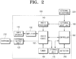
- FIG. 2 is a block diagram of the audio reproducing apparatus 100 as illustrated in FIGS. 1A and 1B .
- the audio reproducing apparatus 100 outputs a reproduced audio file through an internal speaker 110 or an earphone 210 connected to an external output unit 120 to provide the user with the audio.
- the audio file may be any type of file.
- the audio file could be the audio portion of an audio/video (AV) file.
- AV audio/video
- the audio reproducing apparatus 100 comprises an internal speaker 110, an external output unit 120, an amplifier 130, an audio processor 140, an audio codec 150, a tuner 160, a storage unit 170, an external input unit 180, a controller 190, and a detector 200.
- the audio codec 150 reads audio data from a storage unit 170 under the control of the controller 190, and then compresses/decompresses the audio data.
- the amplifier 130 amplifies an audio signal outputted from the audio codec 150.
- the internal speaker 110 is an output element inside the auxiliary casing 100-2, which outputs the audio file amplified by the amplifier 130.
- the external output unit 120 transmits an audio signal outputted from the audio codec 150 through the earphone 210.
- the detector 200 is a detecting element inside the main casing 100-1, detecting movements of the auxiliary casing 100-2. That is, the detector 200 detects the position of the auxiliary casing 100-2, thereby determining whether the state of the audio reproducing apparatus 100 is closed or open.
- FIGS. 3A and 3B are drawings illustrating a method for detecting movements of the auxiliary casing 100-2.
- FIG. 3A illustrates the closed state of the audio reproducing apparatus 100.
- FIG. 3A illustrates the audio reproducing apparatus 100 upside down, with the auxiliary casing 100-2 above the main casing 100-1. That is, the audio reproducing apparatus 100 illustrated in FIG. 3A is a reversed view of the audio reproducing apparatus 100 illustrated in FIG. 1A .
- the detector 200 disposed inside the main casing 100-1 is illustrated in FIG. 3A , and a Hall sensor 205 thereof is also marked with dotted lines.
- the Hall sensor 205 is a sensor detecting vertical incident magnetic field in the sensor surface.
- Other aspects of the present invention may use different types of sensors in different configurations.
- the battery 115 is disposed between the first internal speaker 110-1 and the second internal speaker 110-2 inside the auxiliary casing 100-2. In order to improve space efficiency for the auxiliary casing 100-2, the battery 115 is disposed between the first and second internal speakers 110-1, 110-2. However, according to other aspects, the battery 115 may be located anywhere in the audio reproducing apparatus 100.
- the Hall sensor 205 is positioned adjacent to the second internal speaker 110-2, in the closed state of the audio reproducing apparatus 100.
- the Hall sensor 205 senses the magnetic field through the sensor surface vertical to the magnetic field emitted from the magnetic provided in the internal speaker 110, thereby detecting that the audio reproducing apparatus 100 is in the closed state.
- FIG. 3B illustrates the open state of the audio reproducing apparatus 100.
- the Hall sensor 205 is some distance apart from the second internal speaker 110-2. Accordingly, the Hall sensor 205 cannot sense the magnetic field emitted from the magnetic provided in the internal speaker 110 through the sensor surface, and thereby determines that the audio reproducing apparatus 100 is in the open state.
- the results obtained by the detector 200 according to the above-described method are transmitted to the controller 190.
- control unit 190 determines an appropriate output mode based on the results obtained by the detector 200, and controls the function of the audio reproducing apparatus 100 according to the determined output mode for the audio file.
- the audio output mode comprises an internal output mode in which audio files are outputted from the internal speaker 110 and an external output mode in which audio files are outputted from the earphone 210 through the external output unit 120.
- the control unit 190 sets the audio output mode as an internal output mode if it is appropriate for the audio file to be outputted from the internal speaker 110 based on the movements of the auxiliary casing 100-2. For instance, as illustrated in FIGS. 1B and 3B , the output side of the audio file for the auxiliary casing 100-2 is exposed to the outside.
- the controller 190 sets the audio output mode to an external output mode. This may occur when, as illustrated in FIGS. 1A and 3A , the audio output side of the auxiliary casing 100-2 is covers the lower surface of the main casing 100-1, that is, the audio output side of the auxiliary casing 100-2 is not exposed to the outside.
- the detector 200 detects movements of the auxiliary casing 100-2 and determines the state of the audio reproducing apparatus 100 (S430). A method for detecting movements of the auxiliary casing 100-2 has been described above, with reference to FIGS 3A and 3B .
- the controller 190 changes operation of the audio reproducing apparatus to the external output mode (S440). In such a situation, the audio output side of the auxiliary casing 100-2 is not exposed to the outside. In the external output mode, the audio signal of the audio codec 150 is transmitted to the earphone 210 through the external output unit 120.
- the controller 190 changes operation of the audio reproducing apparatus to the internal output mode (S460). In such a situation, the audio output side of the auxiliary casing 100-2 is exposed to the outside. In the internal output mode, the audio signal of the audio codec 150 is amplified by the amplifier 130 and output through the internal speaker 110.
- the controller 190 controls the audio reproducing apparatus 100 to perform recording (S470).
- the recording mode an analog audio signal is received from the external microphone 220 through the external input unit 180, converted into a digital audio signal by the audio processor 140, compressed in the audio codec 150, and stored in the storage unit 170.
- the detector 200 uses a Hall sensor 205 disposed opposite to the second internal speaker 110-2. It is possible for the detector 200 to use two Hall sensors, each of which are disposed opposite to the first and second internal speakers 110-1, 110-2.
- the Hall sensor which senses the magnetic field through the sensing face vertical to the magnetic field, has been described as an example of an element sensing the magnetic field emitted from the magnet disposed at the internal speaker 110, but it is not limited thereto. Accordingly, the technical concepts of the present invention can be applied by using a horizontal magnetic sensor.
- Both types of magnetic sensor may be appropriate, depending on the position of the internal speaker 110.
- a vertical magnetic sensor may be used when the magnetic field is vertically emitted from the spot where the magnetic field emitted from the internal speaker 110 can be detected. However, if the magnetic field is emitted horizontally to the spot where the magnetic filed emitted from the internal speaker 110 is detected, a horizontal magnetic sensor may be used.
- the detector 200 detects movements of the auxiliary casing 100-2 by sensing the magnetic field emitted from the magnet in the internal speaker 110.
- the present invention also can be applied by using separate magnets other than those in the internal speaker 110. By using the magnet provided at the internal speaker 110, however, there is no need to buy separate magnets. Therefore the cost and size can be reduced.
- the auxiliary casing 100-2 can be detected by sensing the magnetic field, but is not limited thereto. Accordingly, the technical concepts and vision of the present invention can be applied when using magnetic elements such as a magnetic field, electric elements such as an electronic field, light elements such as IR/visible lights, and even electromagnetic elements.
- the auxiliary casing 100-2 is at a predetermined angle of inclination after being slidably guided along a lower surface of the main casing 100-1.
- the auxiliary casing and main casing may be attached by a hinge, about which the auxiliary casing may pivot.
- an audio reproducing apparatus 100 having two casings has been described, according to an exemplary embodiment of the present invention, the present invention can also be applied in the case of an audio reproducing apparatus 100 having three or more casings.
- the technical concepts of the reproducing apparatus can also be applied to any AV reproducing apparatus capable of supporting not only audio reproducing apparatuses such as MP3 players, but also video reproducing apparatuses or apparatuses capable of reproducing both video and audio files (e.g. DMB player, personal digital assistant, video player, HDD player, mobile phone, car navigator etc.).
- AV reproducing apparatus capable of supporting not only audio reproducing apparatuses such as MP3 players, but also video reproducing apparatuses or apparatuses capable of reproducing both video and audio files (e.g. DMB player, personal digital assistant, video player, HDD player, mobile phone, car navigator etc.).
- the reproducing apparatus automatically converts audio and/or video output modes based on movements or position of the casing, therefore preventing inconveniences in converting every output mode for every situation. Furthermore, there is no need for extra components to detect movements of the reproducing apparatus, since existing components, such as the internal speaker, may be used. As a result, the cost and size can be reduced.
- control unit 190 audio codec 150, or audio processor 140
- audio codec 150 may be integrated into a single control unit, or alternatively, can be implemented in software or hardware, such as, for example, a field programmable gate array (FPGA) and an application specific integrated circuit (ASIC).
- FPGA field programmable gate array
- ASIC application specific integrated circuit
- These software modules may include data and instructions which can also be stored on one or more machine-readable storage media, such as dynamic or static read-only memories (EPROMs), electrically erasable and programmable read-only memories (EEPROMs) and flash memories; magnetic disks such as fixed, floppy, and removable disks; other magnetic media including tape; and optical media such as compact discs (CDs) or digital video discs (DVDs).
- EPROMs dynamic or static read-only memories
- EEPROMs electrically erasable and programmable read-only memories
- flash memories such as fixed, floppy, and removable disks; other magnetic media including tape; and optical media such as compact discs (CDs) or digital video discs (DVDs).
- CDs compact discs
- DVDs digital video discs
- code segments including instructions stored on floppy disks, CD or DVD media, a hard disk, or transported through a network interface card, modem, or other interface device may be loaded into the system and executed as corresponding software routines or modules.
- data signals that are embodied as carrier waves (transmitted over telephone lines, network lines, wireless links, cables, and the like) may communicate the code segments, including instructions, to the network node or element.
- carrier waves may be in the form of electrical, optical acoustical, electromagnetic, or other types of signals.
- aspects of the present invention can also be embodied as computer readable codes on a computer readable recording medium.
- the computer readable recording medium may be any data storage device that can store data which can be thereafter read by a computer system. Examples of a computer readable recording medium also include read-only memory (ROM), random access memory (RAM), CD-ROMs, magnetic tapes, floppy disks, optical data storage devices, and carrier waves (such as data transmission through the Internet).
- ROM read-only memory
- RAM random access memory
- CD-ROMs compact discs
- magnetic tapes magnetic tapes
- floppy disks floppy disks
- optical data storage devices such as data transmission through the Internet
- carrier waves such as data transmission through the Internet
- the computer readable recording medium can also be distributed over network coupled computer systems so that the computer readable code is stored and executed in a distributed fashion.
- functional programs, codes, and code segments for accomplishing the present invention can be easily construed by programmers skilled in the art to which the present invention pertains.
- Such a computer program product can be, for example, a series of computer instructions stored on a tangible recording medium, such as diskette, CD-ROM, ROM, or fixed disk, or embodied in a computer data signal, the signal being transmitted over a tangible medium or a wireless medium, for example microwave or infrared.
- the series of computer instructions can constitute all or part of the functionality described above, and can also be stored in any memory device, volatile or non-volatile, such as semiconductor, magnetic, optical, or other memory device.
- the software modules as described can also be machine-readable storage media, such as dynamic or static random access memories (DRAM or SRAM), erasable and programmable read-only memories (EEPROMs), and flash memories; magnetic disks such as fixed, floppy, and removable disks; other magnetic media including tape; and optical media such as compact discs (CDs_ and digital video discs (DVDs). Accordingly, it is intended, therefore, that the present invention not be limited to the various example embodiments disclosed, but that the present invention includes all embodiments falling within the scope of the appended claims.
- DRAM or SRAM dynamic or static random access memories
- EEPROMs erasable and programmable read-only memories
- flash memories such as fixed, floppy, and removable disks
- CDs_ and DVDs digital video discs
Landscapes
- Engineering & Computer Science (AREA)
- Theoretical Computer Science (AREA)
- Physics & Mathematics (AREA)
- Computer Hardware Design (AREA)
- General Physics & Mathematics (AREA)
- General Engineering & Computer Science (AREA)
- Human Computer Interaction (AREA)
- Signal Processing (AREA)
- Mathematical Physics (AREA)
- Health & Medical Sciences (AREA)
- General Health & Medical Sciences (AREA)
- Otolaryngology (AREA)
- Acoustics & Sound (AREA)
- Stereophonic System (AREA)
- Telephone Set Structure (AREA)
Description
- Aspects of the present invention relate to a reproducing apparatus and a method thereof, and more particularly, to a reproducing apparatus capable of reproducing audio and/or video files and a method thereof.
- Recently, electronic device casings have become increasingly diversified and sophisticated, having different kinds of designs. One of the challenges in the diversification in the design for electronic device casings, particularly portable electronic device casings, is to stimulate consumer's aesthetic appeal, thereby increasing sales in existing markets. Another challenge is to reduce the size of the device casings and to provide multi-functional portable electronic device casings.
- In the latter case, the appearance of the electronic device casings can be transformed by the user, such as with a folder type mobile telephone, which can be folded while carrying the phone, and which can be unfolded during operation. In addition, the user may also be inconvenienced when using multi-functional electronic device casings, because the user has to set options related to the function of the device casings. Therefore, methods for improving convenience and simplicity in setting those options related to the function of the device casings are required.
-
US 2003/008689 A1 discloses a wireless portable terminal device which has a first casing and a second casing. Those two casings are coupled to each other, but the main display may be arranged in a folded and an unfolded state. However, this reference does not disclose an internal output unit comprising a speaker that is exposed only in case the second casing is open. -
US 2006/060762 A1 discloses a folding-type mobile telephone. An angle of folding is limited to define a closed and an open position. -
US 2005/083351 A1 discloses a device with magnetic detecting units, wherein the first magnetic detecting unit can detect magnetism of a magnetic circuit of a first speaker and wherein the second magnetic detection unit can detect magnetism of a magnet circuit of a further speaker.JP 2002-368860 A -
US 2006/073859 A1 discloses a sliding mechanism to couple a cover and a body. The cover is slidably disposed above the body and is movable between an open and a closed position. There is no particular predetermined angle of inclination as the angle of inclination according to this reference is adjusted by the user according to his wishes. Moreover, there is no internal output unit or any hint with respect to an output depending on the folded or unfolded status. - Aspects of embodiments of the present invention solve at least the above problems and/or disadvantages and provide at least the advantages described below. Accordingly, aspects of embodiments of the present invention provide a reproducing apparatus according to claim 1 and a method according to claim 11, for converting output mode of an audio and/or a video on the basis of the position or movements of a device casing.
- Additional aspects and/or advantages of the invention will be set forth in the description which follows.
- According to an aspect of the present invention, the detector is disposed at the first casing to detect movements of the second casing relative to the first casing based on whether or not an emission is detected from electronic parts of the second casing.
- According to an aspect of the present invention, the emission from the electronic parts comprises one of electric components, magnetic components, electromagnetic components, and light components.
- According to an aspect of the present invention, the detector detects movements of the second casing relative to the first casing based on whether a magnetic field, emitted by a magnet of the internal speaker provided in the second casing, is detected.
- According to an aspect of the present invention, the detector comprises one of a vertical magnetic sensor to sense the magnetic field through a sensor surface vertical to the magnetic field, and a horizontal magnetic sensor sense the magnetic field through a sensor surface horizontal to the magnetic field.
- According to an aspect of the present invention, one side of the second casing is a side from which the reproduced audio is outputted through the internal output unit.
- According to an aspect of the present invention, detecting the position of the second casing relative to the first casing comprises detecting movements of the second casing relative to the first casing based on whether an emission from electric parts of the second casing is detected.
- According to an aspect of the present invention, the emission from the electric parts comprises any one of electric components, magnetic components, electromagnetic components, and light components.
- According to an aspect of the present invention, detecting the position of the second casing relative to the first casing comprises detecting movements of the second casing relative to the first casing based on whether a magnetic field emitted from a magnet of a speaker in the second casing is detected.
- According to an aspect of the present invention, controlling the output of the reproduced audio comprises outputting the reproduced audio via the internal output unit when the second casing is moved from a position where the second casing covers the first casing to a position where the second casing uncovers the first casing.
- In addition to the example embodiments and aspects as described above, further aspects and embodiments will be apparent by reference to the drawings and by study of the following descriptions.
- A better understanding of the present invention will become apparent from the following detailed description of example embodiments and the claims when read in connection with the accompanying drawings, all forming a part of the disclosure of this invention. While the following written and illustrated disclosure focuses on disclosing example embodiments of the invention, it should be clearly understood that the same is by way of illustration and example only and that the invention is not limited thereto. The scope of the present invention is limited only by the terms of the appended claims. The following represents brief descriptions of the drawings, wherein:
-
FIG. 1A and FIG. 1B are perspective views of an appearance of an audio reproducing apparatus according to an exemplary embodiment of the present invention. -
FIG. 2 is a block diagram of the audio reproducing apparatus according to an exemplary embodiment of the present invention; -
FIG. 3A and FIG. 3B are drawings illustrating a method for detecting movements of a casing of a reproducing apparatus according to an exemplary embodiment of the present invention; and -
FIG. 4 is a flow chart describing a method for automatically converting an output mode based on movements of a casing according to an exemplary embodiment of the present invention. - Reference will now be made in detail to the present embodiments of the present invention, examples of which are illustrated in the accompanying drawings, wherein like reference numerals refer to the like elements throughout. The embodiments are described below in order to explain the present invention by referring to the figures.
-
FIG. 1A and FIG. 1B are perspective views of an appearance of an audio reproducing apparatus according to an exemplary embodiment of the present invention. Theaudio reproducing apparatus 100 may have a structure of a main casing 100-1 combined with an auxiliary casing 100-2. In such a structure, the auxiliary casing 100-2 has a predetermined angle of inclination after being slidably guided along a lower surface of the main casing 100-1. Other examples not falling within the scope of the invention may use different configurations, such as a hinge attaching the auxiliary casing 100-2 to the main casing 100-1. - A display and a control button are located on the outside of the main casing 100-1, and a detecting element (not illustrated), detecting movements of the auxiliary casing 100-2, is located inside the main casing 100-1. Such detecting element will be described later.
- An internal speaker (not illustrated) and a battery (not illustrated) are provided inside the auxiliary casing 100-2. By moving the auxiliary casing 100-2, an audio output surface (illustrated in a checkered pattern) may be up against the lower surface of the main casing 100-1 as illustrated in
FIG. 1A , or exposed to the outside as illustrated inFIG. 1B . Audio files can be transmitted to the user from the audio output side through the internal speaker inside the auxiliary casing 100-2. - A state in which the audio output side of the auxiliary casing 100-2 covers the lower surface of the main casing 100-1 and not to the outside, is a 'closed state' as illustrated in
FIG. 1A . In addition, a state in which the audio output side of the auxiliary casing 100-2 uncovers the lower surface of the main casing 100-1 and is exposed to the outside is an 'open state' as illustrated inFIG. 1B . According to other aspects of the present invention, in the closed state the auxiliary casing may cover only a portion of the main casing 100-1. -
FIG. 2 is a block diagram of theaudio reproducing apparatus 100 as illustrated inFIGS. 1A and 1B . Theaudio reproducing apparatus 100 outputs a reproduced audio file through aninternal speaker 110 or anearphone 210 connected to anexternal output unit 120 to provide the user with the audio. The audio file may be any type of file. For example, the audio file could be the audio portion of an audio/video (AV) file. - The
audio reproducing apparatus 100 comprises aninternal speaker 110, anexternal output unit 120, anamplifier 130, anaudio processor 140, anaudio codec 150, atuner 160, astorage unit 170, anexternal input unit 180, acontroller 190, and adetector 200. - The
audio codec 150 reads audio data from astorage unit 170 under the control of thecontroller 190, and then compresses/decompresses the audio data. - The
amplifier 130 amplifies an audio signal outputted from theaudio codec 150. Theinternal speaker 110 is an output element inside the auxiliary casing 100-2, which outputs the audio file amplified by theamplifier 130. - The
external output unit 120 transmits an audio signal outputted from theaudio codec 150 through theearphone 210. - The
detector 200 is a detecting element inside the main casing 100-1, detecting movements of the auxiliary casing 100-2. That is, thedetector 200 detects the position of the auxiliary casing 100-2, thereby determining whether the state of theaudio reproducing apparatus 100 is closed or open. - A method for detecting movements of the auxiliary casing 100-2 will be described in detail with reference to the accompanying drawing
FIGS. 3A and 3B. FIGS. 3A and 3B are drawings illustrating a method for detecting movements of the auxiliary casing 100-2. -
FIG. 3A illustrates the closed state of theaudio reproducing apparatus 100. For the sake of convenience,FIG. 3A illustrates theaudio reproducing apparatus 100 upside down, with the auxiliary casing 100-2 above the main casing 100-1. That is, theaudio reproducing apparatus 100 illustrated inFIG. 3A is a reversed view of theaudio reproducing apparatus 100 illustrated inFIG. 1A . - The first internal speaker 110-1 and the second internal speaker 110-2 of the
internal speaker 110, located inside the auxiliary casing 100-2, are marked with dotted lines. In addition, thedetector 200 disposed inside the main casing 100-1 is illustrated inFIG. 3A , and aHall sensor 205 thereof is also marked with dotted lines. TheHall sensor 205 is a sensor detecting vertical incident magnetic field in the sensor surface. Other aspects of the present invention may use different types of sensors in different configurations. - The
battery 115 is disposed between the first internal speaker 110-1 and the second internal speaker 110-2 inside the auxiliary casing 100-2. In order to improve space efficiency for the auxiliary casing 100-2, thebattery 115 is disposed between the first and second internal speakers 110-1, 110-2. However, according to other aspects, thebattery 115 may be located anywhere in theaudio reproducing apparatus 100. - As illustrated in
FIG. 3A , theHall sensor 205 is positioned adjacent to the second internal speaker 110-2, in the closed state of theaudio reproducing apparatus 100. TheHall sensor 205 senses the magnetic field through the sensor surface vertical to the magnetic field emitted from the magnetic provided in theinternal speaker 110, thereby detecting that theaudio reproducing apparatus 100 is in the closed state. -
FIG. 3B illustrates the open state of theaudio reproducing apparatus 100. In such state, theHall sensor 205 is some distance apart from the second internal speaker 110-2. Accordingly, theHall sensor 205 cannot sense the magnetic field emitted from the magnetic provided in theinternal speaker 110 through the sensor surface, and thereby determines that theaudio reproducing apparatus 100 is in the open state. - The results obtained by the
detector 200 according to the above-described method are transmitted to thecontroller 190. - Referring again to
FIG. 2 , thecontrol unit 190 determines an appropriate output mode based on the results obtained by thedetector 200, and controls the function of theaudio reproducing apparatus 100 according to the determined output mode for the audio file. - The audio output mode comprises an internal output mode in which audio files are outputted from the
internal speaker 110 and an external output mode in which audio files are outputted from theearphone 210 through theexternal output unit 120. - The
control unit 190 sets the audio output mode as an internal output mode if it is appropriate for the audio file to be outputted from theinternal speaker 110 based on the movements of the auxiliary casing 100-2. For instance, as illustrated inFIGS. 1B and3B , the output side of the audio file for the auxiliary casing 100-2 is exposed to the outside. - If it is inappropriate for the audio file to be outputted from the
internal speaker 110 based on movements of the auxiliary casing 100-2, thecontroller 190 sets the audio output mode to an external output mode. This may occur when, as illustrated inFIGS. 1A and3A , the audio output side of the auxiliary casing 100-2 is covers the lower surface of the main casing 100-1, that is, the audio output side of the auxiliary casing 100-2 is not exposed to the outside. - The operation for setting the audio output mode illustrated in
FIG. 2 will be explained in detail with reference toFIG. 4 . - If an operating mode of the
audio reproducing apparatus 100 is recognized as an audio reproducing mode, thedetector 200 detects movements of the auxiliary casing 100-2 and determines the state of the audio reproducing apparatus 100 (S430). A method for detecting movements of the auxiliary casing 100-2 has been described above, with reference toFIGS 3A and 3B . - If the
audio reproducing apparatus 100 is determined to be in the closed state (S430-Y), thecontroller 190 changes operation of the audio reproducing apparatus to the external output mode (S440). In such a situation, the audio output side of the auxiliary casing 100-2 is not exposed to the outside. In the external output mode, the audio signal of theaudio codec 150 is transmitted to theearphone 210 through theexternal output unit 120. - If the
audio reproducing apparatus 100 is determined to be in the open state (S450-Y), thecontroller 190 changes operation of the audio reproducing apparatus to the internal output mode (S460). In such a situation, the audio output side of the auxiliary casing 100-2 is exposed to the outside. In the internal output mode, the audio signal of theaudio codec 150 is amplified by theamplifier 130 and output through theinternal speaker 110. - If the operating mode of the
audio reproducing apparatus 100 is recognized as a recording mode (S410-N), however, thecontroller 190 controls theaudio reproducing apparatus 100 to perform recording (S470). In the recording mode, an analog audio signal is received from theexternal microphone 220 through theexternal input unit 180, converted into a digital audio signal by theaudio processor 140, compressed in theaudio codec 150, and stored in thestorage unit 170. - A detailed description with reference to an audio reproducing apparatus, which automatically sets an audio output mode appropriately, by detecting the position and/or movement of an auxiliary casing 100-2, has been described above.
- According to an exemplary embodiment of the present invention, the
detector 200 uses aHall sensor 205 disposed opposite to the second internal speaker 110-2. It is possible for thedetector 200 to use two Hall sensors, each of which are disposed opposite to the first and second internal speakers 110-1, 110-2. - According to another exemplary embodiment of the present invention, the Hall sensor, which senses the magnetic field through the sensing face vertical to the magnetic field, has been described as an example of an element sensing the magnetic field emitted from the magnet disposed at the
internal speaker 110, but it is not limited thereto. Accordingly, the technical concepts of the present invention can be applied by using a horizontal magnetic sensor. - Both types of magnetic sensor may be appropriate, depending on the position of the
internal speaker 110. A vertical magnetic sensor may be used when the magnetic field is vertically emitted from the spot where the magnetic field emitted from theinternal speaker 110 can be detected. However, if the magnetic field is emitted horizontally to the spot where the magnetic filed emitted from theinternal speaker 110 is detected, a horizontal magnetic sensor may be used. - According to still another exemplary embodiment of the present invention, the
detector 200 detects movements of the auxiliary casing 100-2 by sensing the magnetic field emitted from the magnet in theinternal speaker 110. However, the present invention also can be applied by using separate magnets other than those in theinternal speaker 110. By using the magnet provided at theinternal speaker 110, however, there is no need to buy separate magnets. Therefore the cost and size can be reduced. - According to still another exemplary embodiment of the present invention, the auxiliary casing 100-2 can be detected by sensing the magnetic field, but is not limited thereto. Accordingly, the technical concepts and vision of the present invention can be applied when using magnetic elements such as a magnetic field, electric elements such as an electronic field, light elements such as IR/visible lights, and even electromagnetic elements.
- The auxiliary casing 100-2 is at a predetermined angle of inclination after being slidably guided along a lower surface of the main casing 100-1. According to an example not falling within the scope of the invention, the auxiliary casing and main casing may be attached by a hinge, about which the auxiliary casing may pivot.
- Although an
audio reproducing apparatus 100 having two casings has been described, according to an exemplary embodiment of the present invention, the present invention can also be applied in the case of anaudio reproducing apparatus 100 having three or more casings. - The technical concepts of the reproducing apparatus, according to exemplary embodiments of the present invention, can also be applied to any AV reproducing apparatus capable of supporting not only audio reproducing apparatuses such as MP3 players, but also video reproducing apparatuses or apparatuses capable of reproducing both video and audio files (e.g. DMB player, personal digital assistant, video player, HDD player, mobile phone, car navigator etc.).
- The reproducing apparatus according to exemplary embodiments of the present invention automatically converts audio and/or video output modes based on movements or position of the casing, therefore preventing inconveniences in converting every output mode for every situation. Furthermore, there is no need for extra components to detect movements of the reproducing apparatus, since existing components, such as the internal speaker, may be used. As a result, the cost and size can be reduced.
- Various components of the audio reproducing apparatus, as shown in
FIGS. 1-3 , such ascontrol unit 190,audio codec 150, oraudio processor 140, may be integrated into a single control unit, or alternatively, can be implemented in software or hardware, such as, for example, a field programmable gate array (FPGA) and an application specific integrated circuit (ASIC). As such, it is intended that the processes described herein to be broadly interpreted as being equivalently performed by software, hardware, or a combination thereof. Software modules can be written via a variety of software languages. These software modules may include data and instructions which can also be stored on one or more machine-readable storage media, such as dynamic or static read-only memories (EPROMs), electrically erasable and programmable read-only memories (EEPROMs) and flash memories; magnetic disks such as fixed, floppy, and removable disks; other magnetic media including tape; and optical media such as compact discs (CDs) or digital video discs (DVDs). For example, code segments including instructions stored on floppy disks, CD or DVD media, a hard disk, or transported through a network interface card, modem, or other interface device may be loaded into the system and executed as corresponding software routines or modules. In the loading or transport process, data signals that are embodied as carrier waves (transmitted over telephone lines, network lines, wireless links, cables, and the like) may communicate the code segments, including instructions, to the network node or element. Such carrier waves may be in the form of electrical, optical acoustical, electromagnetic, or other types of signals. - In addition, aspects of the present invention can also be embodied as computer readable codes on a computer readable recording medium. The computer readable recording medium may be any data storage device that can store data which can be thereafter read by a computer system. Examples of a computer readable recording medium also include read-only memory (ROM), random access memory (RAM), CD-ROMs, magnetic tapes, floppy disks, optical data storage devices, and carrier waves (such as data transmission through the Internet). The computer readable recording medium can also be distributed over network coupled computer systems so that the computer readable code is stored and executed in a distributed fashion. Also, functional programs, codes, and code segments for accomplishing the present invention can be easily construed by programmers skilled in the art to which the present invention pertains.
- While there have been illustrated and described what are considered to be example embodiments of the present invention, it will be understood by those skilled in the art and as technology develops that various changes and modifications, may be made, and equivalents may be substituted for elements thereof without departing from the scope of the present invention. Many modifications, permutations, additions and sub-combinations may be made to adapt the teachings of the present invention to a particular situation without departing from the scope of the appended claims. For example, alternative embodiments of the invention can be implemented as a computer program product for use with a computer system. Such a computer program product can be, for example, a series of computer instructions stored on a tangible recording medium, such as diskette, CD-ROM, ROM, or fixed disk, or embodied in a computer data signal, the signal being transmitted over a tangible medium or a wireless medium, for example microwave or infrared. The series of computer instructions can constitute all or part of the functionality described above, and can also be stored in any memory device, volatile or non-volatile, such as semiconductor, magnetic, optical, or other memory device. Furthermore, the software modules as described can also be machine-readable storage media, such as dynamic or static random access memories (DRAM or SRAM), erasable and programmable read-only memories (EEPROMs), and flash memories; magnetic disks such as fixed, floppy, and removable disks; other magnetic media including tape; and optical media such as compact discs (CDs_ and digital video discs (DVDs). Accordingly, it is intended, therefore, that the present invention not be limited to the various example embodiments disclosed, but that the present invention includes all embodiments falling within the scope of the appended claims.
Claims (15)
- A reproducing apparatus (100) having a first casing (100-1) coupled to a second casing (100-2), comprising:means to slidably guide the second casing (100-2) along a lower surface of the first casing (100-1) from a closed state to an open state, wherein in the closed state the second casing covers the first casing, and wherein in the open state the second casing (100-2) has a predetermined angle of inclination with respect to the first casing (100-1);an internal output unit (110) with an internal speaker (110, 110-1, 110-2) configured to output reproduced audio, the internal output unit (110) provided inside the second casing (100-2);an external output unit (120) configured to output the reproduced audio to an external device (210) being connectable to said external output unit (120);a detector (200, 205) configured to detect movements of the second casing (100-2) relative to the first casing (100-1), to determine if the reproducing apparatus (100) is in the open or in the closed state;a control unit (190) configured to transmit the reproduced audio to the internal speaker of the internal output unit (110) in case the reproducing apparatus is in the open state and to transmit the reproduced audio to the external output unit (120) in case the reproducing apparatus is in the closed state, based on the detection by the detector (200, 205) of the movement of the second casing (100-2) relative to the first casing (100-1),whereinthe internal output unit (110) with its internal speaker (110-1, 110-2) is exposed in response to the reproducing apparatus being in the open state.
- The apparatus according to claim 1, wherein the detector (200, 205) is disposed in the first casing (101-1) and detects movements of the second casing (101-2) relative to the first casing based on whether an emission is detected from electronic parts (110-1, 110-2) of the second casing.
- The apparatus according to claim 2, wherein the emission from the electronic parts comprises electric components.
- The apparatus according to claim 2, wherein the emission from the electronic parts comprises magnetic components.
- The apparatus according to claim 2, wherein the emission from the electronic parts comprises electromagnetic components.
- The apparatus according to claim 2, wherein the emission from the electronic parts comprises light components.
- The apparatus according to claim 2, wherein the detector (200) detects movements of the second casing (100-2) relative to the first casing (100-1) based on whether a magnetic field, emitted by a magnet of said internal speaker (110-1, 110-2) provided in the second casing, is detected.
- The apparatus according to claim 7, wherein the detector (200) comprises a vertical magnetic sensor (205) to sense the magnetic field through a sensor surface vertical to the magnetic field.
- The apparatus according to claim 7, wherein the detector (200) comprises a horizontal magnetic sensor (205) to sense the magnetic field through a sensor surface horizontal to the magnetic field.
- The apparatus according to any one of the preceding claims, wherein one side of the second casing (100-2) is a side from which the reproduced audio is outputted through the internal output unit.
- A method for reproducing audio in a reproducing apparatus (100) having a first casing (100-1) coupled to a second casing (100-2), comprising the steps ofi) detecting (S410, S430, S450) a position of the second casing (100-2) relative to the first casing (100-1), to determine if the reproducing apparatus is in an open or a closed state; wherein in the closed state, the second casing covers the first casing, and in the open state, the second casing is arranged in a predetermined angle of inclination with respect to the first casing (100-1) after being slidably guided along a lower surface of the first casing (100-1) from the closed state;ii) controlling (S440, S460) the transmission of reproduced audio to an internal output unit (110) with an internal speaker (110, 110-1, 110-2) provided inside the second casing (100-2) in case the reproducing apparatus is in the open state and controlling the transmission of the reproduced audio to an external output unit (120) configured to output the reproduced audio to an external device being connectable to the external output unit in case the reproducing apparatus is in the closed state, the control based on the detected position of the second casing (100-2) relative to the first casing (100-1),and exposing the internal output unit (110) with its internal speaker in response to the reproducing apparatus being in the open state.
- The method according to claim 11, wherein detecting the position of the second casing relative to the first casing comprises detecting movements of the second casing relative to the first casing based on whether an emission from electric parts of the second casing is detected.
- The method according to claim 12, wherein the emission from the electric parts comprises any one of electric components, magnetic components, electromagnetic components, and light components.
- The method according to claim 12, wherein detecting the position of the second casing comprises detecting movements of the second casing based on whether a magnetic field emitted from a magnet of the internal speaker in the second casing is detected.
- The method according to any one of claims 11 to 14, wherein controlling the transmission of reproduced audio based on the detected position of the second casing (100-2) relative to the first casing (100-1) comprises outputting the reproduced audio through the internal output unit, which is located in one side of the second casing.
Applications Claiming Priority (1)
| Application Number | Priority Date | Filing Date | Title |
|---|---|---|---|
| KR1020060069395A KR101297181B1 (en) | 2006-07-24 | 2006-07-24 | Apparatus for converting output mode automatically according to movement of case and method thereof |
Publications (3)
| Publication Number | Publication Date |
|---|---|
| EP1883269A2 EP1883269A2 (en) | 2008-01-30 |
| EP1883269A3 EP1883269A3 (en) | 2010-09-01 |
| EP1883269B1 true EP1883269B1 (en) | 2019-06-12 |
Family
ID=38621964
Family Applications (1)
| Application Number | Title | Priority Date | Filing Date |
|---|---|---|---|
| EP07102464.0A Active EP1883269B1 (en) | 2006-07-24 | 2007-02-15 | Reproducing apparatus and method for reproducing audio therefor |
Country Status (4)
| Country | Link |
|---|---|
| US (1) | US8718308B2 (en) |
| EP (1) | EP1883269B1 (en) |
| KR (1) | KR101297181B1 (en) |
| CN (1) | CN101114516A (en) |
Families Citing this family (5)
| Publication number | Priority date | Publication date | Assignee | Title |
|---|---|---|---|---|
| TWI399671B (en) * | 2007-01-19 | 2013-06-21 | Lg Electronics Inc | Inputting information through touch input device |
| US9294840B1 (en) * | 2010-12-17 | 2016-03-22 | Logitech Europe S. A. | Ease-of-use wireless speakers |
| US9807483B1 (en) * | 2016-12-07 | 2017-10-31 | BassCase LLC | Mobile device case with foldable speaker system |
| CN110177318B (en) * | 2019-05-07 | 2021-07-23 | 歌尔股份有限公司 | Vibration sound production device and electronic product |
| CN118044209A (en) * | 2022-08-16 | 2024-05-14 | Lg电子株式会社 | Battery-embedded TV capable of being inserted into a housing and control method thereof |
Citations (2)
| Publication number | Priority date | Publication date | Assignee | Title |
|---|---|---|---|---|
| JP2002368860A (en) * | 2001-06-11 | 2002-12-20 | Kyocera Corp | Mobile terminal device |
| US20060073859A1 (en) * | 2004-10-04 | 2006-04-06 | Peter Chou | Handheld electronic device with dual operation mode |
Family Cites Families (8)
| Publication number | Priority date | Publication date | Assignee | Title |
|---|---|---|---|---|
| JP4470343B2 (en) | 2000-06-22 | 2010-06-02 | ソニー株式会社 | Information browsing apparatus and information output control method |
| JP3636057B2 (en) | 2000-10-13 | 2005-04-06 | ソニー株式会社 | Portable information processing apparatus, information processing method in portable information processing apparatus, and program storage medium in portable information processing apparatus |
| JP2003018078A (en) * | 2001-07-03 | 2003-01-17 | Nec Access Technica Ltd | Radio mobile terminal unit, received call loudspeaking method, and program thereof |
| US7443404B2 (en) * | 2003-10-17 | 2008-10-28 | Casio Computer Co., Ltd. | Image display apparatus, image display controlling method, and image display program |
| TWI391776B (en) | 2004-03-08 | 2013-04-01 | Pentax Ricoh Imaging Co Ltd | Anti-shock device |
| KR100661543B1 (en) | 2004-06-24 | 2006-12-27 | 엘지전자 주식회사 | Apparatus and method for converting voice path of swivel mobile terminal |
| US7196316B2 (en) * | 2004-09-22 | 2007-03-27 | Avago Technologies Ecbu Ip (Singapore) Pte. Ltd. | Portable electronic device with activation sensor |
| US20070252853A1 (en) | 2006-04-28 | 2007-11-01 | Samsung Electronics Co., Ltd. | Method and apparatus to control screen orientation of user interface of portable device |
-
2006
- 2006-07-24 KR KR1020060069395A patent/KR101297181B1/en active Active
-
2007
- 2007-01-26 US US11/698,095 patent/US8718308B2/en active Active
- 2007-02-15 EP EP07102464.0A patent/EP1883269B1/en active Active
- 2007-03-14 CN CNA2007100857607A patent/CN101114516A/en active Pending
Patent Citations (2)
| Publication number | Priority date | Publication date | Assignee | Title |
|---|---|---|---|---|
| JP2002368860A (en) * | 2001-06-11 | 2002-12-20 | Kyocera Corp | Mobile terminal device |
| US20060073859A1 (en) * | 2004-10-04 | 2006-04-06 | Peter Chou | Handheld electronic device with dual operation mode |
Also Published As
| Publication number | Publication date |
|---|---|
| EP1883269A3 (en) | 2010-09-01 |
| EP1883269A2 (en) | 2008-01-30 |
| KR20080009598A (en) | 2008-01-29 |
| US8718308B2 (en) | 2014-05-06 |
| US20080019550A1 (en) | 2008-01-24 |
| KR101297181B1 (en) | 2013-08-21 |
| CN101114516A (en) | 2008-01-30 |
Similar Documents
| Publication | Publication Date | Title |
|---|---|---|
| US12375863B2 (en) | Systems and methods for equalizing audio for playback on an electronic device | |
| US9065410B2 (en) | Automatic audio equalization using handheld mode detection | |
| JP5973465B2 (en) | Audio processing device | |
| US7522065B2 (en) | Method and apparatus for proximity sensing in a portable electronic device | |
| US20060073844A1 (en) | Electronic device with ambient light sensor | |
| US8718308B2 (en) | Reproducing apparatus and method for automatically converting output mode based on movements of casing | |
| JP2006340180A (en) | Method for controlling antenna of portable terminal device and portable terminal device | |
| KR100453042B1 (en) | A portable telephone, control method, and recording medium therefor | |
| CN102292965A (en) | Portable Electronic Devices with Slide and Tilt Mechanisms | |
| US12443241B2 (en) | Electronic device protective case and electronic device assembly | |
| KR20080073853A (en) | Apparatus and method for automatically adjusting sound and portable terminal using same | |
| JP5391999B2 (en) | Portable recording apparatus, recording automatic adjustment method, and program | |
| CN117795981A (en) | Electronic device for correcting sound signals and method for controlling electronic device | |
| JP5109378B2 (en) | Portable terminal device, method for controlling portable terminal device, and program | |
| WO2017170566A1 (en) | Portable information terminal cover and portable information terminal program | |
| US9513616B2 (en) | System and method for controlling functions on electronic devices | |
| EP2442537B1 (en) | System and method for controlling functions on electronic devices | |
| CN114157742A (en) | Folding mechanism and mobile terminal | |
| JP2008193288A (en) | Mobile wireless device and antenna switching method, and program | |
| KR102074315B1 (en) | Sound book | |
| JP4304886B2 (en) | Foldable mobile phone and its open / close detection method | |
| WO2002096711A1 (en) | Multifunctional car stereo, particularly for motor vehicles and the like | |
| US20050157197A1 (en) | Image photographing apparatus | |
| CA2492953A1 (en) | Cellular phone | |
| JP2007073157A (en) | Media playback apparatus and media playback method |
Legal Events
| Date | Code | Title | Description |
|---|---|---|---|
| PUAI | Public reference made under article 153(3) epc to a published international application that has entered the european phase |
Free format text: ORIGINAL CODE: 0009012 |
|
| AK | Designated contracting states |
Kind code of ref document: A2 Designated state(s): AT BE BG CH CY CZ DE DK EE ES FI FR GB GR HU IE IS IT LI LT LU LV MC NL PL PT RO SE SI SK TR |
|
| AX | Request for extension of the european patent |
Extension state: AL BA HR MK YU |
|
| PUAL | Search report despatched |
Free format text: ORIGINAL CODE: 0009013 |
|
| AK | Designated contracting states |
Kind code of ref document: A3 Designated state(s): AT BE BG CH CY CZ DE DK EE ES FI FR GB GR HU IE IS IT LI LT LU LV MC NL PL PT RO SE SI SK TR |
|
| AX | Request for extension of the european patent |
Extension state: AL BA HR MK RS |
|
| RIC1 | Information provided on ipc code assigned before grant |
Ipc: H04R 3/12 20060101ALI20100727BHEP Ipc: H04R 5/04 20060101ALN20100727BHEP Ipc: G06F 1/16 20060101ALI20100727BHEP Ipc: H04M 1/02 20060101AFI20100727BHEP |
|
| 17P | Request for examination filed |
Effective date: 20110301 |
|
| AKX | Designation fees paid |
Designated state(s): DE GB NL |
|
| 17Q | First examination report despatched |
Effective date: 20110415 |
|
| RAP1 | Party data changed (applicant data changed or rights of an application transferred) |
Owner name: SAMSUNG ELECTRONICS CO., LTD. |
|
| REG | Reference to a national code |
Ref country code: DE Ref legal event code: R079 Ref document number: 602007058555 Country of ref document: DE Free format text: PREVIOUS MAIN CLASS: H04R0005020000 Ipc: H04M0001020000 |
|
| GRAP | Despatch of communication of intention to grant a patent |
Free format text: ORIGINAL CODE: EPIDOSNIGR1 |
|
| RIC1 | Information provided on ipc code assigned before grant |
Ipc: H04M 1/02 20060101AFI20181213BHEP Ipc: H04R 3/12 20060101ALI20181213BHEP Ipc: H04R 5/04 20060101ALN20181213BHEP Ipc: H04M 1/725 20060101ALN20181213BHEP Ipc: G06F 1/16 20060101ALI20181213BHEP |
|
| INTG | Intention to grant announced |
Effective date: 20190108 |
|
| RIC1 | Information provided on ipc code assigned before grant |
Ipc: H04M 1/725 20060101ALN20181218BHEP Ipc: H04R 5/04 20060101ALN20181218BHEP Ipc: G06F 1/16 20060101ALI20181218BHEP Ipc: H04R 3/12 20060101ALI20181218BHEP Ipc: H04M 1/02 20060101AFI20181218BHEP |
|
| RIN1 | Information on inventor provided before grant (corrected) |
Inventor name: CHO, JANG-HWAN Inventor name: CHO, KYUNG-SUK Inventor name: PARK, SOON Inventor name: JEONG, BYONG-WOO |
|
| INTG | Intention to grant announced |
Effective date: 20190108 |
|
| GRAS | Grant fee paid |
Free format text: ORIGINAL CODE: EPIDOSNIGR3 |
|
| GRAA | (expected) grant |
Free format text: ORIGINAL CODE: 0009210 |
|
| AK | Designated contracting states |
Kind code of ref document: B1 Designated state(s): DE GB NL |
|
| REG | Reference to a national code |
Ref country code: GB Ref legal event code: FG4D |
|
| REG | Reference to a national code |
Ref country code: DE Ref legal event code: R096 Ref document number: 602007058555 Country of ref document: DE |
|
| REG | Reference to a national code |
Ref country code: NL Ref legal event code: FP |
|
| REG | Reference to a national code |
Ref country code: DE Ref legal event code: R097 Ref document number: 602007058555 Country of ref document: DE |
|
| PLBE | No opposition filed within time limit |
Free format text: ORIGINAL CODE: 0009261 |
|
| STAA | Information on the status of an ep patent application or granted ep patent |
Free format text: STATUS: NO OPPOSITION FILED WITHIN TIME LIMIT |
|
| 26N | No opposition filed |
Effective date: 20200313 |
|
| PGFP | Annual fee paid to national office [announced via postgrant information from national office to epo] |
Ref country code: NL Payment date: 20260121 Year of fee payment: 20 |
|
| PGFP | Annual fee paid to national office [announced via postgrant information from national office to epo] |
Ref country code: GB Payment date: 20260122 Year of fee payment: 20 |
|
| PGFP | Annual fee paid to national office [announced via postgrant information from national office to epo] |
Ref country code: DE Payment date: 20260120 Year of fee payment: 20 |