EP1883261A1 - Base station, mobile station, mobile communication system and control signal transmission control method - Google Patents
Base station, mobile station, mobile communication system and control signal transmission control method Download PDFInfo
- Publication number
- EP1883261A1 EP1883261A1 EP06729482A EP06729482A EP1883261A1 EP 1883261 A1 EP1883261 A1 EP 1883261A1 EP 06729482 A EP06729482 A EP 06729482A EP 06729482 A EP06729482 A EP 06729482A EP 1883261 A1 EP1883261 A1 EP 1883261A1
- Authority
- EP
- European Patent Office
- Prior art keywords
- control signal
- layer control
- transmitting
- base station
- mobile station
- Prior art date
- Legal status (The legal status is an assumption and is not a legal conclusion. Google has not performed a legal analysis and makes no representation as to the accuracy of the status listed.)
- Withdrawn
Links
Images




Classifications
-
- H—ELECTRICITY
- H04—ELECTRIC COMMUNICATION TECHNIQUE
- H04W—WIRELESS COMMUNICATION NETWORKS
- H04W72/00—Local resource management
- H04W72/20—Control channels or signalling for resource management
- H04W72/23—Control channels or signalling for resource management in the downlink direction of a wireless link, i.e. towards a terminal
-
- H—ELECTRICITY
- H04—ELECTRIC COMMUNICATION TECHNIQUE
- H04B—TRANSMISSION
- H04B1/00—Details of transmission systems, not covered by a single one of groups H04B3/00 - H04B13/00; Details of transmission systems not characterised by the medium used for transmission
- H04B1/69—Spread spectrum techniques
- H04B1/707—Spread spectrum techniques using direct sequence modulation
-
- H—ELECTRICITY
- H04—ELECTRIC COMMUNICATION TECHNIQUE
- H04L—TRANSMISSION OF DIGITAL INFORMATION, e.g. TELEGRAPHIC COMMUNICATION
- H04L1/00—Arrangements for detecting or preventing errors in the information received
- H04L1/0001—Systems modifying transmission characteristics according to link quality, e.g. power backoff
- H04L1/0002—Systems modifying transmission characteristics according to link quality, e.g. power backoff by adapting the transmission rate
- H04L1/0003—Systems modifying transmission characteristics according to link quality, e.g. power backoff by adapting the transmission rate by switching between different modulation schemes
-
- H—ELECTRICITY
- H04—ELECTRIC COMMUNICATION TECHNIQUE
- H04W—WIRELESS COMMUNICATION NETWORKS
- H04W48/00—Access restriction; Network selection; Access point selection
- H04W48/08—Access restriction or access information delivery, e.g. discovery data delivery
- H04W48/12—Access restriction or access information delivery, e.g. discovery data delivery using downlink control channel
-
- H—ELECTRICITY
- H04—ELECTRIC COMMUNICATION TECHNIQUE
- H04W—WIRELESS COMMUNICATION NETWORKS
- H04W72/00—Local resource management
- H04W72/20—Control channels or signalling for resource management
- H04W72/21—Control channels or signalling for resource management in the uplink direction of a wireless link, i.e. towards the network
-
- H—ELECTRICITY
- H04—ELECTRIC COMMUNICATION TECHNIQUE
- H04B—TRANSMISSION
- H04B2201/00—Indexing scheme relating to details of transmission systems not covered by a single group of H04B3/00 - H04B13/00
- H04B2201/69—Orthogonal indexing scheme relating to spread spectrum techniques in general
- H04B2201/707—Orthogonal indexing scheme relating to spread spectrum techniques in general relating to direct sequence modulation
- H04B2201/70703—Orthogonal indexing scheme relating to spread spectrum techniques in general relating to direct sequence modulation using multiple or variable rates
- H04B2201/70705—Rate detection
Definitions
- the present invention relates to a base station, a mobile station, a mobile communication system, and a method of controlling control signal transmission.
- a base station transmits to a mobile station a data information signal, and an upper-layer control signal (e.g., user information, user authentication, and a control signal for handover when a user moves from one cell to another).
- an upper-layer control signal e.g., user information, user authentication, and a control signal for handover when a user moves from one cell to another.
- a base station in downlink, dedicated channels allocating a specific code to a certain user and a shared channel shared by all users are provided.
- a base station multiplexes transmission data of each channel in code domain (see e.g., Non-Patent Document 1). Specifically, a base station includes a Forward Access Channel (FACH) and a Broadcast Channel.
- FACH Forward Access Channel
- the FACH a channel for multiplexing control information of each user on a time axis, is used mainly for exchanging an upper layer signal at the time of a call setup. This signal is mapped onto a Secondary Common Control Channel in physical layer. For example, the FACH is used in a Random Access Channel response.
- a Broadcast Channel is a channel for reporting broadcast information common to all users (e.g., system information, or cell information). These signals are mapped onto a Primary Common Control Channel.
- a base station uses a Random Access Channel.
- the Random Access Channel is a channel for transmitting upper-layer control information.
- the control information is mapped onto a Physical Random Channel.
- HS-SCCH High Speed Shared Control Channel
- HS-PDSCH High Speed Physical Downlink Shared Channel
- HS-SCCH conducts, in a Shared CH, Layers 1 and 2 signalling at the time of HS-PDSCH transmission for high-speed packet transmission.
- Information transmitted using this HS-SCCH including user information and MCS (Modulation & Coding scheme Set), are code-multiplexed with a HS-PDSCH.
- Non-Patent Document 1 3GPP TS 25.212
- Non-Patent Document 2 3GPP TS 25.213
- an upper-layer control signal e.g., a signal indicating an authentication in a case of a call setup and a report on a reception status in case of a handover
- a data signal are respectively input to corresponding channel encoders, then encoded data are fed into to a multiplexer.
- CRC addition, Rate Matching and channel coding are performed at the channel encoder.
- the multiplexer multiplexes the encoded upper-layer control signal and encoded data signal. Then, multiplexed signals are fed into a control-channel specific physical or dedicated channel.
- W-CDMA since the transmission rate of specific control channel is approximately 3.4 kbps, large transmission delay occurs and a call set up, e.g., an authentication, or a call connection, takes time.
- a base station In circuit-switching, numerous low-rate channels are used for transmitting voice and control signals.
- a base station as shown in FIG. 2, multiplexes (code-multiplexes) to control-specific channels signals destined for multiple users as shown for a user 1 data signal, a user N data signal, and a control signal, or multiplexes (code-multiplexes) with other signals after pre-multiplexing data and control signals as shown for user 2 data and control signals.
- a base station in an embodiment of the present invention includes a transmission-rate determining unit for determining a transmission rate of a control channel for transmitting an upper-layer control signal, and a transmitter for allocating a predetermined bandwidth (e.g. number of sub-carriers (or resource blocks)) to the control channel for transmitting the upper-layer control signal according to the determined transmission rate.
- a predetermined bandwidth e.g. number of sub-carriers (or resource blocks)
- the base station makes it possible to control the transmission rate for transmitting a control signal according to a traffic condition, or urgency (priority) of the control signal, for example.
- a base station in another embodiment of the present invention includes an upper-layer control signal determining unit for determining whether a control signal transmitted from a mobile station indicates transmitting an upper-layer control signal, a channel-allocating unit for allocating a UL-SCH (Uplink Shared Channel) to the mobile station, and a reporting unit for transmitting an allocation-reporting packet for reporting that the UL-SCH has been allocated to the mobile station.
- an upper-layer control signal determining unit for determining whether a control signal transmitted from a mobile station indicates transmitting an upper-layer control signal
- a channel-allocating unit for allocating a UL-SCH (Uplink Shared Channel) to the mobile station
- a reporting unit for transmitting an allocation-reporting packet for reporting that the UL-SCH has been allocated to the mobile station.
- the base station makes it possible to allocate an UL-SCH to an upper-layer control signal transmitted by a mobile station.
- a base station in a further embodiment of the present invention includes an upper-layer control signal transmitter for multiplexing to a UL-SCH, upper-layer control signals to transmit a multiplexed signal.
- the base station makes it possible to transmit an upper-layer control signal using an UL-SCH normally used as a data CH.
- the base station in a mobile communication system including a mobile station and a base station, includes a upper-layer control signal determining unit for determining whether a control signal transmitted from a mobile station indicates transmitting an upper-layer control signal, a channel-allocating unit for allocating a UL-SCH to the mobile station, and a reporting unit for transmitting an allocation-reporting packet for reporting that the UL-SCH has been allocated to the mobile station, and the mobile station includes a transmitter for transmitting a control signal for indicating transmitting an upper-layer control signal, a lower-layer control signal determining unit for determining whether an allocation-reporting packet transmitted from the base station is destined for the mobile station itself, and an upper-layer control signal transmitter for multiplexing upper-layer control signals to the UL-SCH to transmit a multiplexed upper-layer control signal.
- the mobile station makes it possible to transmit an upper-layer control signal using a UL-SCH allocated to a base station.
- a method of controlling control signal transmission in an embodiment of the present invention includes steps of: determining a transmission rate of a control channel for transmitting an upper-layer control signal, allocating a predetermined bandwidth to a control channel for transmitting the upper-layer control signal according to the determined transmission rate, and transmitting the upper-layer control signal to which the predetermined bandwidth is allocated.
- the method of controlling control signal transmission according to an embodiment of the present invention makes it possible to control a transmission rate for transmitting a control signal according to a traffic condition, or urgency (priority) of a control signal, for example.
- a method of controlling control signal transmission in another embodiment of the present invention includes the steps of: transmitting a control signal indicating transmitting an upper-layer control signal, determining whether the transmitted control signal indicates transmitting the upper-layer control signal, allocating a UL-SCH based on the determining, transmitting an allocation-reporting packet for reporting that the UL-SCH has been allocated, determining whether the allocation-reporting packet is destined for a station itself, and multiplexing to the UL-SCH, upper-layer control signals to transmit a multiplexed signal based on the determining of whether the allocation-reporting packet is destined for the station itself.
- the mobile station makes it possible to allocate a UL-SCH (Uplink Shared Channel) to an upper-layer control signal transmitted by a mobile station.
- UL-SCH Uplink Shared Channel
- a base station, a mobile station, a mobile communication system, and a method of controlling control information transmission may be realized which make it possible to reduce transmission time of a control signal.
- a mobile communication system includes a base station 100, and a mobile station 200 which can wirelessly communicate with the base station 100.
- the base station 100 In order to realize a network having a small delay, the base station 100 according to the embodiment has a high-speed data channel (below called Data CH) to which control signals are multiplexed. Moreover, the base station 100 uses this Data CH and provides absolute priorities in scheduling. This makes it possible to prevent a delay in scheduling.
- Data CH high-speed data channel
- the base station 100 has a downlink scheduler 102 and a transmitter 104 connected to the downlink scheduler 102, the transmitter 104 being means for determining transmission rate and means for transmitting.
- the downlink scheduler 102 has a buffer 112 to which an upper-layer control signal (a signal indicating, e.g., an authentication at the time of call setup, or a report on the reception state at the time of handover), and one or multiple buffers 114 1 to 114 n (where n is an integer such that n ⁇ 1), to which data signals are input.
- the downlink scheduler 102 includes a scheduler 116 connected to the buffer 112 and the buffers 114 1 to 114 n , and an encoder 118 connected to the scheduler 116.
- the encoder 118 is connected to the transmitter 104.
- the buffer 112 temporarily stores an upper-layer control signal input.
- the buffers 114 1 to 114 n temporarily store data signals input.
- the upper-layer control signal and the data signals are transmitted over the same physical cable.
- the scheduler 116 selects, from upper-layer control and data signals stored in the buffer 112 and buffers 114 1 to 114 n , a signal to be transmitted with priority, and inputs the selected signal to the encoder 118. For example, the scheduler 116 sets a priority order (priority) per buffer as illustrated in FIG. 4. In this case, the scheduler 116 sets information stored in the buffer 112 as a highest-priority queue such that any information incoming to this queue is transmitted unconditionally. In other words, the scheduler 116 preferentially inputs an upper-layer control signal in case of any upper-layer control signal being input to the buffer 112.
- an IP packet is determined as to whether an IP packet is an upper-layer control signal by referring to a flag appended to its header, which flag indicating whether it is an upper-layer control signal.
- an IP packet is provided with a predetermined field such that, according to the value of the field, it is stored in buffer 112 or buffers 114 1 to 114 n depending on whether it is determined as an upper-layer control signal or a data signal.
- the field is set such that the IP packet is an upper-layer control signal when the value of the field is 0 and a data signal when the value of the field is 1, which field is referred to in order to determine whether it is an upper-layer control signal.
- This feature makes it possible to store, in an IP packet, control information in addition to data, QoS information, and information indicating whether it is data to be given priority, and to transmit the IP packet.
- the encoder 118 encodes a signal input and outputs the coded signal to the transmitter 104.
- the transmitter 104 modulates the coded signal, and transmits the modulated signal using a shared channel.
- the transmitter 104 high-speed transmits the coded signal at the transmission rate of 10 Mbps, for example.
- the shared channel is shared by multiple users with one slot taken up by at least one user. This makes it possible to significantly reduce the time to transmit a control signal.
- the scheduler 116 sets a priority for an upper-layer control signal, and outputs the upper-layer control signal to the encoder according to the priority set.
- one buffer may be provided for temporarily storing an upper-layer control signal and a data signal.
- the scheduler 116 refers to an IP packet header, determines whether the IP packet is an upper-layer control signal, and inputs to the encoder 118 the IP packet based on the result of the determination.
- a base station 100 in the embodiment provides for a high-speed slot dedicated to a control channel in order to realize a network with a small delay.
- Each user control channel set as code-multiplexed is variably set according to information required.
- the base station 100 includes encoders 120 1 -120 N , users 1-N data signals input to the respective encoders; an encoder 122 to which a control signal is input; primary modulators 124 1 -124 N and 126 connected to the respective encoders 120 1 -120 N and 122; a multiplexer 128 connected to the primary modulators 124 1 -124 N and 126, the primary modulators being means for determining transmission rate and means for transmitting; and a secondary modulator 130 connected to the multiplexer 128.
- the encoders 120 1 -120 N code the input data signals and outputs the respective coded data signals to the respective primary modulators 124 1 -124 N .
- the primary modulators 124 1 -124 N primary-modulate the coded signals input and output the primary-modulated signals to the multiplexer 128.
- the encoder 122 codes an input control signal and outputs the coded signal to the primary modulator 126.
- the primary modulator 126 primary-modulates the coded signal input and outputs the primary-modulated signal to the multiplexer 128.
- the multiplexer 128 allocates bandwidths to the primary-modulated data signals and control signal input, multiplexes the input signals, and outputs a multiplexed signal to the secondary multiplexer 130. For example, the multiplexer 128 allocates a 32 kHz bandwidth to each user data signal. Moreover, the multiplexer 128 variably allocates the bandwidth to be allocated to the control signal in the range of 32kHz -10MHz, for example. In this way, setting a Control CH for transmitting a control signal as a variable bandwidth signal makes it possible to control the transmission rate of a control channel for transmitting the control signal according to traffic conditions, or urgency (priority) of the control signal. In this case, the multiplexer 128, for example, controls the transmission rate to be approximately 500 kbps for an HO control signal, and approximately 1 Mbps for a call setup.
- multiplexer 128 time-multiplexes the primary-multiplexed data signals and control signal. As illustrated in FIG.7, the multiplexer 128 allocates to multiple slots a control CH and data CHs. In this case, either code multiplexing or frequency multiplexing among users is performed within a slot to which a control CH is allocated (called a control CH slot).
- slots to which a control CH and data CHs are allocated are variably set.
- the base station 100 reports to the mobile station 200 the position of a slot to which a control CH is allocated.
- the multiplexer 128 may allocate the control CH and data CHs to multiple slots in a fixed manner. This makes it possible for the base station 100 to eliminate reporting to the mobile station 200 of the position of the slot to which the control CH is allocated.
- the multiplexer 128 may allocate control CH and data CHs to multiple slots in a fixed manner, while variably allocating additional control CH and data CHs to slots. In this case, the base station 100 needs to report the position of a control CH slot to the mobile station 200.
- the multiplexer 128 may, for example, frequency-multiplex the primary-multiplexed data signals and control signal. As illustrated in FIG. 8, the multiplexer 128 allocates to multiple sub-carriers control and data CHs. In this case, either code multiplexing or time multiplexing is performed among users within the sub-carrier to which a control CH is allocated.
- the multiplexer 128 sets, for the multiple sub-carriers, the sub-carriers to which control CHs are allocated as variable.
- the base station 100 reports the position of a control CH sub-carrier to the mobile station 200.
- the control CH sub-carrier takes a comb-shaped pattern in an uplink.
- the multiplexer 128 may make a fixed allocation of control CHs to sub-carriers. This makes it possible for the base station 100 to eliminate reporting to the mobile station 200 the position of a sub-carrier to which a control CH is allocated.
- the multiplexer 128 may make a fixed allocation of control CHs to sub-carriers while variably allocating additional control CHs to sub-carriers.
- the base station 100 needs to report to the mobile station 200 the position of a sub-carrier to which a control CH is allocated.
- the multiplexer 128 may, for example, code-multiplex the primary-multiplexed data signals and control signal.
- the multiplexer 128, as illustrated in FIG. 9, allocates spread codes to a control CH and a data CH. In this case, either code multiplexing or time multiplexing among users using control CHs of the same spread code is performed.
- the multiplexer 128 variably sets spread code numbers and spreading rates for control CHs.
- the base station 100 reports to the mobile station 200 a spread code number allocated to a control CH.
- the multiplexer 128 may fix the setting of some spread code numbers and spreading rates for control CHs while variably setting additional spread code numbers and spreading rates for control CHs.
- the base station 100 needs to report to the mobile station 200 a spread code number allocated to a control CH.
- the secondary modulator 130 secondary-modulates the primary-modulated data and control signals multiplexed and transmits a secondary-modulated signal.
- control CH itself is bandwidth-variable. For example, for 2 or 3 users, the users take up bandwidth for transmitting data signals with the remaining bandwidth allocated to control CHs. This makes it possible to control the transmission rate of the control signal.
- a lower-layer control signal represents information such as channel allocation information, ACK, and NACK.
- allocated channels and codes are designated by an upper-level station and not by a base station.
- a base station does the designating.
- a base station maps to a Physical CH a lower-level control signal, for example, channel allocation information, and transmits the mapped signal to the mobile station. In this case, not performing error detection would lead to the mobile station continuing to operate in error. Therefore, the base station appends to a lower-level control signal an error-detecting code according to its use.
- the encoder 122 appends error-detecting codes to the control signal according to use such as demodulating, decoding, and retransmitting.
- error-detecting codes are appended to groups of control signals classified according to use.
- a unit for appending the error-detecting code eg., length
- Appending one error-detecting signal to a group rather than an individual one of lower-level control signals results in a larger number of bits to be error-detected, causing a larger probability of a detection error. Appending an error-detecting code individually according to use in this way makes it possible to improve the error-detecting accuracy.
- a unit for error-correction coding is one or more error-detecting codes.
- the error-detecting codes may be varied according to control-signal group bit groups. It is also possible to allow at least one error-correction coding block in one wireless frame.
- a mobile station 200 transmits with a RACH (Random Access CHannel) to a base station 100 a control signal indicating a data transmission request.
- the base station 100 allocates codes to the mobile station 200 and transmits with a FACH a control signal indicating data communication permission.
- the mobile station 200 transmits with a DCCH (Dedicated Control CHannel) to the base station 100 an upper-layer signal in codes allocated.
- RACH Random Access CHannel
- DCCH Dedicated Control CHannel
- the mobile station 200 uses a UL-SCH (Uplink Shared Channel) to transmit to a base station 100 an upper-layer control signal.
- UL-SCH Uplink Shared Channel
- a base station 100 according to the embodiment of the present invention is described with reference to FIG. 12.
- the base station 100 includes an upper-layer control signal determining unit 152, a channel-allocating unit 154 connected to the upper-layer control signal determining unit 152, and a transmitter 156 connected to the channel-allocating unit 154, the transmitter 156 being reporting means.
- the upper-layer control signal determining unit 152 determines whether a below-described control signal transmitted from the mobile station 200 with a Reservation control CH is a signal indicating transmitting an upper-layer control signal.
- the upper-layer control signal determining unit 152 refers to a predetermined flag in a transmitted IP packet to determine whether the flag indicates transmitting an upper-layer control signal.
- a predetermined field is provided for in an IP packet that allows determining, according to the value of the field, whether transmitting an upper-layer control signal is indicated therein.
- the channel-allocating unit 154 allocates an upper UL-SCH when a control signal transmitted from the mobile station 200 with the Reservation control CH indicates transmitting an upper-layer control signal. In this case, the channel-allocating unit 154 allocates a UL-SCH according to the amount of information.
- the transmitter 156 makes a report (an allocation report) to the mobile station 200 which has transmitted the Reservation control CH, indicating that a UL-SCH has been allocated. For example, a user ID and a MCS (Modulation & Coding scheme Set) are stored in a packet indicating an allocation report. Instruction information indicating which multiplexing scheme to transmit with is stored in the MCS.
- a report an allocation report
- MCS Modulation & Coding scheme Set
- the mobile station 200 includes a receiver 252, a lower-layer control signal determining unit 254 connected to the receiver 252, and a transmit data generator 256 connected to the lower-layer control signal determining unit 254, the transmit data generator 256 serving as means for generating a control signal and means for transmitting an upper-layer control signal.
- the receiver 252 receives an allocation report from the base station 100, and inputs the received report to the lower-layer control signal determining unit 254.
- the lower-layer control signal determining unit 254 determines as to whether a user ID stored in the input allocation report matches an ID of the mobile station 200 itself, and, if yes, instructs the transmit data generator 256 to generate transmit data.
- the transmit data generator 256 generates a control signal indicating transmitting an upper-layer control signal and transmits the generated signal. For example, the transmit data generator 256 transmits with a Reserved control CH an IP packet with a flag indicating transmitting an upper-layer control signal. Moreover, the transmit data generator 256 refers to MCS information stored in the allocation report to transmit the upper-layer control signal.
- the transmit data generator 256 of the mobile station 200 transmits with the Reservation control CH to the base station 100 a control signal indicating transmitting an upper-layer control signal.
- the base station 100 in the upper-layer control signal determining unit 152 determines whether the received control signal is a control signal indicating transmitting an upper-layer control signal. If yes, the channel-allocating unit 154 preferentially allocates an uplink UL-SCH to the mobile station 200. Then, the transmitter 156 makes a report (allocation report) that the uplink UL-SCH has been allocated to the mobile station 200. In this case, the channel-allocating unit 154 allocates according to the amount of information.
- the receiver 252 in the mobile station 200 Upon receiving the allocation report, the receiver 252 in the mobile station 200 inputs the allocation report to the lower-layer control signal determining unit 254.
- the lower-layer control signal determining unit 254 determines whether an ID stored in the allocation report input matches an ID of the mobile station 200. If yes, the transmit data generator 256 transmits with a UL-SCH an upper-layer control signal according to an MCS stored in the allocation report.
- circuit switching In circuit switching, a circuit is set up during a communication, while not being able to stop for other communications.
- packet transmission communications in voice, also in packets, can be stopped temporarily, eg., for approximately 20-50 ms. Thus, it is possible to transmit a control signal.
- a traffic-state reporting unit for measuring the traffic state and reporting the result to the mobile station 200 may be provided in the base station 100 with an upper-layer control signal transmitted by the mobile station 200 based on the reported traffic state.
- the mobile station 200 directly transmits a high-speed control channel in a high-speed generator 256 without undergoing a reservation procedure.
- control signal transmitting has been described in a manner such that it is divided into downlink and uplink.
- downlink has been described for the downlink scheduler and multiplexer 128 in the first and second embodiments
- uplink has been described for the upper-layer control signal determining unit 152 and the channel-allocating unit 154 in the third embodiment.
- An actual base station may be provided with a downlink scheduler, a multiplexer 128, an upper-layer control signal determining unit 152, and a channel-allocating unit 154.
- the base station, mobile station, mobile communication system, and a method of controlling control signal transmission according to the present invention is applicable to a mobile communication system.
Landscapes
- Engineering & Computer Science (AREA)
- Computer Networks & Wireless Communication (AREA)
- Signal Processing (AREA)
- Quality & Reliability (AREA)
- Computer Security & Cryptography (AREA)
- Mobile Radio Communication Systems (AREA)
Abstract
Description
- The present invention relates to a base station, a mobile station, a mobile communication system, and a method of controlling control signal transmission.
- In W-CDMA (Wideband-CDMA) and HSDPA (High-Speed Downlink Packet Access), an enhanced technology of W-CDMA, for example, a base station transmits to a mobile station a data information signal, and an upper-layer control signal (e.g., user information, user authentication, and a control signal for handover when a user moves from one cell to another).
- In W-CDMA, in downlink, dedicated channels allocating a specific code to a certain user and a shared channel shared by all users are provided. A base station multiplexes transmission data of each channel in code domain (see e.g., Non-Patent Document 1). Specifically, a base station includes a Forward Access Channel (FACH) and a Broadcast Channel.
- The FACH, a channel for multiplexing control information of each user on a time axis, is used mainly for exchanging an upper layer signal at the time of a call setup. This signal is mapped onto a Secondary Common Control Channel in physical layer. For example, the FACH is used in a Random Access Channel response. A Broadcast Channel is a channel for reporting broadcast information common to all users (e.g., system information, or cell information). These signals are mapped onto a Primary Common Control Channel.
- Moreover, in W-CDMA, in an uplink channel, a base station uses a Random Access Channel. The Random Access Channel is a channel for transmitting upper-layer control information. The control information is mapped onto a Physical Random Channel.
- On the other hand, in HSPDA, in a downlink, HS-SCCH (High Speed Shared Control Channel) and HS-PDSCH (High Speed Physical Downlink Shared Channel) are added to W-CDMA.
- HS-SCCH conducts, in a Shared CH,
Layers - HS-DPCCH conducts, in a dedicated CH,
Layers
Non-PatentDocument 1
3GPP TS 25.212
Non-PatentDocument 2
3GPP TS 25.213 - However, the related art as described above has the following problems.
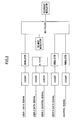
- There is a problem that a specific low rate control increases a control delay. For example, as shown in FIG. 1, an upper-layer control signal (e.g., a signal indicating an authentication in a case of a call setup and a report on a reception status in case of a handover) and a data signal are respectively input to corresponding channel encoders, then encoded data are fed into to a multiplexer. CRC addition, Rate Matching and channel coding are performed at the channel encoder.
- The multiplexer multiplexes the encoded upper-layer control signal and encoded data signal. Then, multiplexed signals are fed into a control-channel specific physical or dedicated channel. In W-CDMA, since the transmission rate of specific control channel is approximately 3.4 kbps, large transmission delay occurs and a call set up, e.g., an authentication, or a call connection, takes time.
- In circuit-switching, numerous low-rate channels are used for transmitting voice and control signals. When there are signals destined for multiple users, a base station, as shown in FIG. 2, multiplexes (code-multiplexes) to control-specific channels signals destined for multiple users as shown for a
user 1 data signal, a user N data signal, and a control signal, or multiplexes (code-multiplexes) with other signals after pre-multiplexing data and control signals as shown foruser 2 data and control signals. - When packet switching is introduced, there is a requirement to satisfy the demand for transmitting when data are available, and connecting when desired with short latency.
- It is a general object of the present invention to provide a base station, a mobile station, a mobile communication system, and a method of controlling control information transmission that makes it possible to reduce control signal transmission time.
- In order to solve at least one of the above-described problems, a base station in an embodiment of the present invention includes a transmission-rate determining unit for determining a transmission rate of a control channel for transmitting an upper-layer control signal, and a transmitter for allocating a predetermined bandwidth (e.g. number of sub-carriers (or resource blocks)) to the control channel for transmitting the upper-layer control signal according to the determined transmission rate.
- The base station according to an embodiment of the present invention makes it possible to control the transmission rate for transmitting a control signal according to a traffic condition, or urgency (priority) of the control signal, for example.
- A base station in another embodiment of the present invention includes an upper-layer control signal determining unit for determining whether a control signal transmitted from a mobile station indicates transmitting an upper-layer control signal, a channel-allocating unit for allocating a UL-SCH (Uplink Shared Channel) to the mobile station, and a reporting unit for transmitting an allocation-reporting packet for reporting that the UL-SCH has been allocated to the mobile station.
- The base station according to another embodiment of the present invention makes it possible to allocate an UL-SCH to an upper-layer control signal transmitted by a mobile station.
- Moreover, a base station in a further embodiment of the present invention includes an upper-layer control signal transmitter for multiplexing to a UL-SCH, upper-layer control signals to transmit a multiplexed signal.
- The base station according to a further embodiment of the present invention makes it possible to transmit an upper-layer control signal using an UL-SCH normally used as a data CH.
- Furthermore, in an embodiment of the present invention, in a mobile communication system including a mobile station and a base station, the base station includes a upper-layer control signal determining unit for determining whether a control signal transmitted from a mobile station indicates transmitting an upper-layer control signal, a channel-allocating unit for allocating a UL-SCH to the mobile station, and a reporting unit for transmitting an allocation-reporting packet for reporting that the UL-SCH has been allocated to the mobile station, and the mobile station includes a transmitter for transmitting a control signal for indicating transmitting an upper-layer control signal, a lower-layer control signal determining unit for determining whether an allocation-reporting packet transmitted from the base station is destined for the mobile station itself, and an upper-layer control signal transmitter for multiplexing upper-layer control signals to the UL-SCH to transmit a multiplexed upper-layer control signal.
- The mobile station according to an embodiment of the present invention makes it possible to transmit an upper-layer control signal using a UL-SCH allocated to a base station.
- A method of controlling control signal transmission in an embodiment of the present invention includes steps of: determining a transmission rate of a control channel for transmitting an upper-layer control signal, allocating a predetermined bandwidth to a control channel for transmitting the upper-layer control signal according to the determined transmission rate, and transmitting the upper-layer control signal to which the predetermined bandwidth is allocated.
- The method of controlling control signal transmission according to an embodiment of the present invention makes it possible to control a transmission rate for transmitting a control signal according to a traffic condition, or urgency (priority) of a control signal, for example.
- Moreover, a method of controlling control signal transmission in another embodiment of the present invention includes the steps of: transmitting a control signal indicating transmitting an upper-layer control signal, determining whether the transmitted control signal indicates transmitting the upper-layer control signal, allocating a UL-SCH based on the determining, transmitting an allocation-reporting packet for reporting that the UL-SCH has been allocated, determining whether the allocation-reporting packet is destined for a station itself, and multiplexing to the UL-SCH, upper-layer control signals to transmit a multiplexed signal based on the determining of whether the allocation-reporting packet is destined for the station itself.
- The mobile station according to an embodiment of the present invention makes it possible to allocate a UL-SCH (Uplink Shared Channel) to an upper-layer control signal transmitted by a mobile station.
- According to at least one of the embodiments of the present invention, a base station, a mobile station, a mobile communication system, and a method of controlling control information transmission may be realized which make it possible to reduce transmission time of a control signal.
-
- FIG. 1 illustrates a partial block diagram showing a base station;
- FIG. 2 illustrates another partial block diagram showing a base station;
- FIG. 3 illustrates a partial block diagram showing a base station according to an embodiment of the present invention;
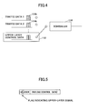
- FIG. 4 illustrates an explanatory diagram showing an operation of a base station according to an embodiment of the present invention;
- FIG. 5 illustrates an explanatory diagram showing an IP packet;
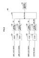
- FIG. 6 illustrates a partial block diagram showing a base station according to an embodiment of the present invention;
- FIG. 7 illustrates an explanatory diagram showing an operation of a base station according to an embodiment of the present invention;
- FIG. 8 illustrates another explanatory diagram showing an operation of a base station according to an embodiment of the present invention;
- FIG. 9 illustrates a further explanatory diagram showing an operation of a base station according to an embodiment of the present invention;
- FIG. 10 illustrates an explanatory diagram showing an operation of a base station according to an embodiment of the present invention;
- FIG. 11 illustrates a sequence diagram showing an operation of a mobile communication system;
- FIG. 12 illustrates a partial block diagram showing a base station according to an embodiment of the present invention;
- FIG. 13 illustrates a partial block diagram showing a mobile station according to an embodiment of the present invention;
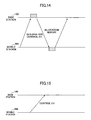
- FIG. 14 illustrates a sequence diagram showing an operation of a mobile communication system according to one embodiment of the present invention; and
- FIG. 15 illustrates another sequence diagram showing an operation of a mobile communication system according to one embodiment of the present invention.
-
- 100 Base station
- 200 Mobile station
- Preferred embodiments of the present invention are described with reference to the drawings.
- Throughout the drawings for explaining the embodiments, the same letters are used for those parts having the same functions, facilitating avoiding repetitive explanation.
- A mobile communication system according to an embodiment of the present invention includes a
base station 100, and amobile station 200 which can wirelessly communicate with thebase station 100. - A
base station 100 according to a first embodiment of the present invention is described with reference to FIG. 3. - In order to realize a network having a small delay, the
base station 100 according to the embodiment has a high-speed data channel (below called Data CH) to which control signals are multiplexed. Moreover, thebase station 100 uses this Data CH and provides absolute priorities in scheduling. This makes it possible to prevent a delay in scheduling. - The
base station 100 has adownlink scheduler 102 and atransmitter 104 connected to thedownlink scheduler 102, thetransmitter 104 being means for determining transmission rate and means for transmitting. Thedownlink scheduler 102 has abuffer 112 to which an upper-layer control signal (a signal indicating, e.g., an authentication at the time of call setup, or a report on the reception state at the time of handover), and one or multiple buffers 1141 to 114n (where n is an integer such that n≧1), to which data signals are input. Moreover, thedownlink scheduler 102 includes ascheduler 116 connected to thebuffer 112 and the buffers 1141 to 114n, and anencoder 118 connected to thescheduler 116. Theencoder 118 is connected to thetransmitter 104. - The
buffer 112 temporarily stores an upper-layer control signal input. The buffers 1141 to 114n temporarily store data signals input. The upper-layer control signal and the data signals are transmitted over the same physical cable. - The
scheduler 116 selects, from upper-layer control and data signals stored in thebuffer 112 and buffers 1141 to 114n, a signal to be transmitted with priority, and inputs the selected signal to theencoder 118. For example, thescheduler 116 sets a priority order (priority) per buffer as illustrated in FIG. 4. In this case, thescheduler 116 sets information stored in thebuffer 112 as a highest-priority queue such that any information incoming to this queue is transmitted unconditionally. In other words, thescheduler 116 preferentially inputs an upper-layer control signal in case of any upper-layer control signal being input to thebuffer 112. - For example, as illustrated in FIG. 5, it is determined as to whether an IP packet is an upper-layer control signal by referring to a flag appended to its header, which flag indicating whether it is an upper-layer control signal. For example, an IP packet is provided with a predetermined field such that, according to the value of the field, it is stored in
buffer 112 or buffers 1141 to 114n depending on whether it is determined as an upper-layer control signal or a data signal. In this case, the field is set such that the IP packet is an upper-layer control signal when the value of the field is 0 and a data signal when the value of the field is 1, which field is referred to in order to determine whether it is an upper-layer control signal. - This feature makes it possible to store, in an IP packet, control information in addition to data, QoS information, and information indicating whether it is data to be given priority, and to transmit the IP packet.
- The
encoder 118 encodes a signal input and outputs the coded signal to thetransmitter 104. Thetransmitter 104 modulates the coded signal, and transmits the modulated signal using a shared channel. For example, thetransmitter 104 high-speed transmits the coded signal at the transmission rate of 10 Mbps, for example. For example, the shared channel is shared by multiple users with one slot taken up by at least one user. This makes it possible to significantly reduce the time to transmit a control signal. - While the embodiment describes a case of providing one buffer for temporarily storing an upper-layer control signal, multiple buffers may be provided for temporarily storing upper-layer control signals to multiple users. In this case, the
scheduler 116 sets a priority for an upper-layer control signal, and outputs the upper-layer control signal to the encoder according to the priority set. - Moreover, in the embodiment, one buffer may be provided for temporarily storing an upper-layer control signal and a data signal. In this case, the
scheduler 116 refers to an IP packet header, determines whether the IP packet is an upper-layer control signal, and inputs to theencoder 118 the IP packet based on the result of the determination. - Now a
base station 100 according to a second embodiment of the present invention is described with reference to FIG. 6. - A
base station 100 in the embodiment provides for a high-speed slot dedicated to a control channel in order to realize a network with a small delay. Each user control channel set as code-multiplexed is variably set according to information required. - The
base station 100 includes encoders 1201-120N, users 1-N data signals input to the respective encoders; anencoder 122 to which a control signal is input; primary modulators 1241-124N and 126 connected to the respective encoders 1201-120N and 122; amultiplexer 128 connected to the primary modulators 1241-124N and 126, the primary modulators being means for determining transmission rate and means for transmitting; and asecondary modulator 130 connected to themultiplexer 128. - The encoders 1201-120N code the input data signals and outputs the respective coded data signals to the respective primary modulators 1241-124N. The primary modulators 1241-124N primary-modulate the coded signals input and output the primary-modulated signals to the
multiplexer 128. Moreover, theencoder 122 codes an input control signal and outputs the coded signal to theprimary modulator 126. Theprimary modulator 126 primary-modulates the coded signal input and outputs the primary-modulated signal to themultiplexer 128. - The
multiplexer 128 allocates bandwidths to the primary-modulated data signals and control signal input, multiplexes the input signals, and outputs a multiplexed signal to thesecondary multiplexer 130. For example, themultiplexer 128 allocates a 32 kHz bandwidth to each user data signal. Moreover, themultiplexer 128 variably allocates the bandwidth to be allocated to the control signal in the range of 32kHz -10MHz, for example. In this way, setting a Control CH for transmitting a control signal as a variable bandwidth signal makes it possible to control the transmission rate of a control channel for transmitting the control signal according to traffic conditions, or urgency (priority) of the control signal. In this case, themultiplexer 128, for example, controls the transmission rate to be approximately 500 kbps for an HO control signal, and approximately 1 Mbps for a call setup. - For example,
multiplexer 128 time-multiplexes the primary-multiplexed data signals and control signal. As illustrated in FIG.7, themultiplexer 128 allocates to multiple slots a control CH and data CHs. In this case, either code multiplexing or frequency multiplexing among users is performed within a slot to which a control CH is allocated (called a control CH slot). - Specifically, slots to which a control CH and data CHs are allocated are variably set. In this case, the
base station 100 reports to themobile station 200 the position of a slot to which a control CH is allocated. - Moreover, the
multiplexer 128 may allocate the control CH and data CHs to multiple slots in a fixed manner. This makes it possible for thebase station 100 to eliminate reporting to themobile station 200 of the position of the slot to which the control CH is allocated. - Furthermore, the
multiplexer 128 may allocate control CH and data CHs to multiple slots in a fixed manner, while variably allocating additional control CH and data CHs to slots. In this case, thebase station 100 needs to report the position of a control CH slot to themobile station 200. - Moreover, the
multiplexer 128 may, for example, frequency-multiplex the primary-multiplexed data signals and control signal. As illustrated in FIG. 8, themultiplexer 128 allocates to multiple sub-carriers control and data CHs. In this case, either code multiplexing or time multiplexing is performed among users within the sub-carrier to which a control CH is allocated. - Specifically, the
multiplexer 128 sets, for the multiple sub-carriers, the sub-carriers to which control CHs are allocated as variable. In this case, thebase station 100 reports the position of a control CH sub-carrier to themobile station 200. The control CH sub-carrier takes a comb-shaped pattern in an uplink. - Moreover, the
multiplexer 128 may make a fixed allocation of control CHs to sub-carriers. This makes it possible for thebase station 100 to eliminate reporting to themobile station 200 the position of a sub-carrier to which a control CH is allocated. - Furthermore, the
multiplexer 128 may make a fixed allocation of control CHs to sub-carriers while variably allocating additional control CHs to sub-carriers. In this case, thebase station 100 needs to report to themobile station 200 the position of a sub-carrier to which a control CH is allocated. - Moreover, the
multiplexer 128 may, for example, code-multiplex the primary-multiplexed data signals and control signal, Themultiplexer 128, as illustrated in FIG. 9, allocates spread codes to a control CH and a data CH. In this case, either code multiplexing or time multiplexing among users using control CHs of the same spread code is performed. - Specifically, the
multiplexer 128 variably sets spread code numbers and spreading rates for control CHs. In this case, thebase station 100 reports to the mobile station 200 a spread code number allocated to a control CH. - Furthermore, the
multiplexer 128 may fix the setting of some spread code numbers and spreading rates for control CHs while variably setting additional spread code numbers and spreading rates for control CHs. In this case, thebase station 100 needs to report to the mobile station 200 a spread code number allocated to a control CH. - The
secondary modulator 130 secondary-modulates the primary-modulated data and control signals multiplexed and transmits a secondary-modulated signal. - As described above, in the embodiment, the control CH itself is bandwidth-variable. For example, for 2 or 3 users, the users take up bandwidth for transmitting data signals with the remaining bandwidth allocated to control CHs. This makes it possible to control the transmission rate of the control signal.
- Now transmission control of lower-layer control information is described. A lower-layer control signal represents information such as channel allocation information, ACK, and NACK.
- In W-CDMA, for example, allocated channels and codes are designated by an upper-level station and not by a base station. However, in HSDPA, a base station does the designating. In HSDPA, a base station maps to a Physical CH a lower-level control signal, for example, channel allocation information, and transmits the mapped signal to the mobile station. In this case, not performing error detection would lead to the mobile station continuing to operate in error. Therefore, the base station appends to a lower-level control signal an error-detecting code according to its use.
- Specifically, as illustrated in FIG. 10, the
encoder 122 appends error-detecting codes to the control signal according to use such as demodulating, decoding, and retransmitting. For example, error-detecting codes are appended to groups of control signals classified according to use. In this case, a unit for appending the error-detecting code (eg., length) may be set variable, or the error-detecting codes may be set as the same or different. Appending one error-detecting signal to a group rather than an individual one of lower-level control signals results in a larger number of bits to be error-detected, causing a larger probability of a detection error. Appending an error-detecting code individually according to use in this way makes it possible to improve the error-detecting accuracy. - Moreover, a unit for error-correction coding is one or more error-detecting codes. Furthermore, the error-detecting codes may be varied according to control-signal group bit groups. It is also possible to allow at least one error-correction coding block in one wireless frame.
- Up to now, such control has not been done in a Physical CH. The feature of the embodiment as described above makes it possible to reduce negotiations from an upper-side or upper layer.
- Now a mobile communication system according to a third embodiment of the present invention is described.
- Methods of improving the transmission rate of the downlink for transmitting an upper-layer control signal have been described for the first and second embodiments.
- In the embodiment, a method of improving the transmission rate for an uplink for transmitting an upper-layer control signal is described.
- First, a procedure for a mobile station transmitting to a base station an upper-layer signal is described with reference to FIG. 11.
- A
mobile station 200 transmits with a RACH (Random Access CHannel) to a base station 100 a control signal indicating a data transmission request. Thebase station 100 allocates codes to themobile station 200 and transmits with a FACH a control signal indicating data communication permission. Themobile station 200 transmits with a DCCH (Dedicated Control CHannel) to thebase station 100 an upper-layer signal in codes allocated. - In this case, however, a low rate of the DCCH leads to a longer time for transmitting an upper-layer control signal from the
mobile station 200 to thebase station 100. Thus, in a mobile communication system according to the embodiment, themobile station 200 uses a UL-SCH (Uplink Shared Channel) to transmit to abase station 100 an upper-layer control signal. - A
base station 100 according to the embodiment of the present invention is described with reference to FIG. 12. - The
base station 100 according to the present invention includes an upper-layer controlsignal determining unit 152, a channel-allocatingunit 154 connected to the upper-layer controlsignal determining unit 152, and atransmitter 156 connected to the channel-allocatingunit 154, thetransmitter 156 being reporting means. - The upper-layer control
signal determining unit 152 determines whether a below-described control signal transmitted from themobile station 200 with a Reservation control CH is a signal indicating transmitting an upper-layer control signal. - For example, the upper-layer control
signal determining unit 152 refers to a predetermined flag in a transmitted IP packet to determine whether the flag indicates transmitting an upper-layer control signal. For example, a predetermined field is provided for in an IP packet that allows determining, according to the value of the field, whether transmitting an upper-layer control signal is indicated therein. - The channel-allocating
unit 154 allocates an upper UL-SCH when a control signal transmitted from themobile station 200 with the Reservation control CH indicates transmitting an upper-layer control signal. In this case, the channel-allocatingunit 154 allocates a UL-SCH according to the amount of information. - The
transmitter 156 makes a report (an allocation report) to themobile station 200 which has transmitted the Reservation control CH, indicating that a UL-SCH has been allocated. For example, a user ID and a MCS (Modulation & Coding scheme Set) are stored in a packet indicating an allocation report. Instruction information indicating which multiplexing scheme to transmit with is stored in the MCS. - Now a
mobile station 200 according to the embodiment of the present invention is described with reference to FIG. 13. - The
mobile station 200 according to the embodiment includes areceiver 252, a lower-layer controlsignal determining unit 254 connected to thereceiver 252, and a transmitdata generator 256 connected to the lower-layer controlsignal determining unit 254, the transmitdata generator 256 serving as means for generating a control signal and means for transmitting an upper-layer control signal. - The
receiver 252 receives an allocation report from thebase station 100, and inputs the received report to the lower-layer controlsignal determining unit 254. - The lower-layer control
signal determining unit 254 determines as to whether a user ID stored in the input allocation report matches an ID of themobile station 200 itself, and, if yes, instructs the transmitdata generator 256 to generate transmit data. - The transmit
data generator 256 generates a control signal indicating transmitting an upper-layer control signal and transmits the generated signal. For example, the transmitdata generator 256 transmits with a Reserved control CH an IP packet with a flag indicating transmitting an upper-layer control signal. Moreover, the transmitdata generator 256 refers to MCS information stored in the allocation report to transmit the upper-layer control signal. - Now a mobile communication system according to the embodiment of the present invention is described with reference to FIG. 14.
- First, the transmit
data generator 256 of themobile station 200 transmits with the Reservation control CH to the base station 100 a control signal indicating transmitting an upper-layer control signal. - The
base station 100 in the upper-layer controlsignal determining unit 152 determines whether the received control signal is a control signal indicating transmitting an upper-layer control signal. If yes, the channel-allocatingunit 154 preferentially allocates an uplink UL-SCH to themobile station 200. Then, thetransmitter 156 makes a report (allocation report) that the uplink UL-SCH has been allocated to themobile station 200. In this case, the channel-allocatingunit 154 allocates according to the amount of information. - Upon receiving the allocation report, the
receiver 252 in themobile station 200 inputs the allocation report to the lower-layer controlsignal determining unit 254. The lower-layer controlsignal determining unit 254 determines whether an ID stored in the allocation report input matches an ID of themobile station 200. If yes, the transmitdata generator 256 transmits with a UL-SCH an upper-layer control signal according to an MCS stored in the allocation report. - This makes it possible for the
mobile station 200 to use the UL-SCH to transmit an upper-layer control signal using approximately 1 MHz bandwidth. Moreover, setting thebase station 100 to allocate a bandwidth to an upper-layer control signal according to the amount of information makes it possible to reduce the transmission power expended by themobile station 200. - In circuit switching, a circuit is set up during a communication, while not being able to stop for other communications. In packet transmission, communications in voice, also in packets, can be stopped temporarily, eg., for approximately 20-50 ms. Thus, it is possible to transmit a control signal.
- In the present embodiment, a case has been described such that the
mobile station 200 transmits an upper-layer control channel after a Reservation control CH transmission and a UL-SCH allocation. However, as illustrated in FIG. 15, a traffic-state reporting unit for measuring the traffic state and reporting the result to themobile station 200 may be provided in thebase station 100 with an upper-layer control signal transmitted by themobile station 200 based on the reported traffic state. In this case, themobile station 200 directly transmits a high-speed control channel in a high-speed generator 256 without undergoing a reservation procedure. - In the above-described embodiments, control signal transmitting has been described in a manner such that it is divided into downlink and uplink. Specifically, downlink has been described for the downlink scheduler and
multiplexer 128 in the first and second embodiments, while uplink has been described for the upper-layer controlsignal determining unit 152 and the channel-allocatingunit 154 in the third embodiment. An actual base station may be provided with a downlink scheduler, amultiplexer 128, an upper-layer controlsignal determining unit 152, and a channel-allocatingunit 154. - The present application claims priority based on
Japanese Patent Application No. 2005-102872 - The base station, mobile station, mobile communication system, and a method of controlling control signal transmission according to the present invention is applicable to a mobile communication system.
Claims (14)
- A base station, comprising:a transmission-rate determining unit for determining a transmission rate of a control channel for transmitting an upper-layer control signal; anda transmitter for, based on a predetermined transmission rate, allocating a predetermined bandwidth to the control channel for transmitting the upper-layer control signal, and transmitting the signal.
- The base station as claimed in claim 1, further comprising:a scheduler for determining a transmission order of the upper-layer control signal and one or a plurality of data signals; whereinthe transmitter transmits the upper-layer control signal and the data signals according to the transmission order.
- The base station as claimed in claim 2, wherein
the scheduler provides a highest-priority transmission order to the upper-layer control signal. - The base station as claimed in claim 2, wherein
the scheduler uses a flag appended to an IP packet to determine whether the IP packet includes an upper-layer control signal. - The base station as claimed in claim 1, wherein
the transmitter allocates to the control channel transmitting the upper-layer control signal a bandwidth, the bandwidth being what remains after one or a plurality of bandwidths are taken up for transmitting one or a plurality of data signals. - A base station, comprising:an upper-layer control signal determining unit for determining whether a control signal transmitted from a mobile station indicates transmitting an upper-layer control signal;a channel-allocating unit for allocating a UL-SCH to the mobile station based on the determination; anda reporting unit for transmitting an allocation-reporting packet for reporting that the UL-SCH has been allocated to the mobile station.
- The base station as claimed in claim 6, wherein
the reporting unit stores a user ID and an MCS in the allocation-reporting packet. - A mobile station, comprising:an upper-layer control signal transmitter for multiplexing one or a plurality of upper-layer control signals so as to transmit a multiplexed signal.
- The mobile station as claimed in claim 8, further comprising:a control-signal generator for generating a control signal indicating transmitting the upper-layer control signal; anda lower-layer control signal determining unit for determining whether an allocation-reporting packet transmitted from the base station is destined for the mobile station, the packet indicating that a UL-SCH has been allocated to the mobile station; whereinthe upper-layer control signal transmitter, based on the determination, multiplexes the upper-layer control signals for a UL-SCH to transmit a multiplexed signal.
- The mobile station as claimed in claim 8, wherein
the upper-layer control signal transmitter, based on a signal indicating a state of traffic transmitted from the base station, multiplexes the upper-layer control signals for a UL-SCH to transmit a multiplexed signal. - A mobile communication system having a mobile station and a base station, wherein the base station includes:an upper-layer control signal determining unit for determining whether a control signal transmitted from a mobile station indicates transmitting an upper-layer control signal;a channel-allocating unit for allocating an UL-SCH to the mobile station based on the determination; anda reporting unit for transmitting an allocation-reporting packet for reporting that the UL-SCH has been allocated to the mobile station, and wherein the mobile station includes:a control-signal generator for generating a control signal indicating transmitting the upper-layer control signal;a lower-layer control signal determining unit for determining whether an allocation-reporting packet transmitted from the base station is destined for the mobile station; andan upper-layer control signal transmitter for multiplexing for the UL-SCH a plurality of upper-layer control signals so as to transmit a multiplexed signal.
- A method of controlling control signal transmission, comprising the steps of:determining a transmission rate of a control channel for transmitting an upper-layer control signal;according to the determined transmission rate, allocating a predetermined bandwidth to a control channel for transmitting the upper-layer control signal; andtransmitting the upper-layer control signal to which the determined bandwidth is allocated.
- The method as claimed in claim 12, further comprising the step of:determining a transmission order of the upper layer control signal and one or a plurality of data signals; whereinthe transmitting step includes transmitting the upper-layer control signal and the data signals according to the transmission order.
- A method of controlling control signal transmission, comprising the steps of:generating a control signal indicating transmitting an upper-layer control signal;determining whether a transmitted control signal indicates transmitting an upper-layer control signal;allocating a UL-SCH based on the determination;transmitting an allocation-reporting packet for reporting that the UL-SCH has been allocated;determining whether the allocation-reporting packet is destined for a mobile station itself; andbased on the determination whether the allocation-reporting packet is destined for the mobile station itself, multiplexing for the UL-SCH a plurality of upper-layer control signals so as to transmit a multiplexed signal.
Applications Claiming Priority (2)
| Application Number | Priority Date | Filing Date | Title |
|---|---|---|---|
| JP2005102872A JP4640786B2 (en) | 2005-03-31 | 2005-03-31 | Base station and transmission method |
| PCT/JP2006/305514 WO2006109438A1 (en) | 2005-03-31 | 2006-03-20 | Base station, mobile station, mobile communication system and control signal transmission control method |
Publications (2)
| Publication Number | Publication Date |
|---|---|
| EP1883261A1 true EP1883261A1 (en) | 2008-01-30 |
| EP1883261A4 EP1883261A4 (en) | 2012-07-25 |
Family
ID=37086729
Family Applications (1)
| Application Number | Title | Priority Date | Filing Date |
|---|---|---|---|
| EP06729482A Withdrawn EP1883261A4 (en) | 2005-03-31 | 2006-03-20 | BASE STATION, MOBILE STATION, MOBILE COMMUNICATION SYSTEM, AND CONTROL SIGNAL TRANSMISSION CONTROL METHOD |
Country Status (9)
| Country | Link |
|---|---|
| US (2) | US8391146B2 (en) |
| EP (1) | EP1883261A4 (en) |
| JP (1) | JP4640786B2 (en) |
| KR (2) | KR101205798B1 (en) |
| CN (1) | CN101171865A (en) |
| BR (1) | BRPI0609588A2 (en) |
| RU (1) | RU2405283C2 (en) |
| TW (1) | TW200644680A (en) |
| WO (1) | WO2006109438A1 (en) |
Families Citing this family (6)
| Publication number | Priority date | Publication date | Assignee | Title |
|---|---|---|---|---|
| KR101352980B1 (en) * | 2006-11-01 | 2014-01-22 | 삼성전자주식회사 | Method and apparatus for transmitting and receiving control information and packet data in Downlink |
| JP4818081B2 (en) * | 2006-11-30 | 2011-11-16 | 京セラ株式会社 | Allocation method and base station apparatus using the same |
| JP5057459B2 (en) * | 2006-12-19 | 2012-10-24 | イノヴァティヴ ソニック リミテッド | CPC improvement method, communication apparatus, and resource decoding instruction method |
| US8121218B2 (en) * | 2007-05-29 | 2012-02-21 | Samsung Electronics Co., Ltd | Apparatus and method for mapping symbols to resources in a mobile communication system |
| KR101447750B1 (en) * | 2008-01-04 | 2014-10-06 | 엘지전자 주식회사 | How to Perform a Random Access Procedure |
| US10135831B2 (en) * | 2011-01-28 | 2018-11-20 | F5 Networks, Inc. | System and method for combining an access control system with a traffic management system |
Family Cites Families (20)
| Publication number | Priority date | Publication date | Assignee | Title |
|---|---|---|---|---|
| JP3039903B2 (en) * | 1994-08-15 | 2000-05-08 | 日本電信電話株式会社 | Control signal transmission method of PHS system |
| JPH0955764A (en) * | 1995-08-14 | 1997-02-25 | Nippon Telegr & Teleph Corp <Ntt> | Wireless packet communication method |
| JPH09289684A (en) * | 1996-04-23 | 1997-11-04 | Matsushita Electric Ind Co Ltd | Wireless communication system |
| US7184426B2 (en) * | 2002-12-12 | 2007-02-27 | Qualcomm, Incorporated | Method and apparatus for burst pilot for a time division multiplex system |
| JP3881770B2 (en) | 1998-03-10 | 2007-02-14 | 松下電器産業株式会社 | Mobile station apparatus and communication method |
| DE69923898T2 (en) * | 1998-03-14 | 2006-04-27 | Samsung Electronics Co., Ltd., Suwon | Apparatus and method for exchanging frame messages of different lengths in a CDMA communication system |
| US7197017B1 (en) * | 2000-01-04 | 2007-03-27 | Qualcomm, Incorporated | Method and apparatus for channel optimization during point-to-point protocol (PPP) session requests |
| AU2001240443A1 (en) * | 2000-01-25 | 2001-08-07 | Siemens Aktiengesellschaft | Method for signaling a channel assignment in a radio communication system |
| DE10119449A1 (en) * | 2001-04-20 | 2002-10-24 | Siemens Ag | Transmitting data of subscriber-specific control channel in radio system by adaptive variation of frequency position for dedicated physical control channel |
| GB2377585B (en) | 2001-07-06 | 2005-08-24 | Ipwireless Inc | Communication resource access request |
| JP3479777B2 (en) * | 2001-08-27 | 2003-12-15 | 日本電信電話株式会社 | Radio transmitting station and radio receiving station for spread spectrum radio communication |
| US7433971B2 (en) * | 2001-11-16 | 2008-10-07 | Intel Corporation | Interface and related methods for dynamic channelization in an ethernet architecture |
| JP3967115B2 (en) | 2001-11-22 | 2007-08-29 | 株式会社エヌ・ティ・ティ・ドコモ | Base station, radio resource control apparatus, terminal apparatus, communication system, and communication method |
| JP3597516B2 (en) | 2002-05-30 | 2004-12-08 | 松下電器産業株式会社 | Scheduling device and communication method |
| TWI237459B (en) * | 2002-10-17 | 2005-08-01 | Interdigital Tech Corp | Power control for communications systems utilizing high speed shared channels |
| WO2004066661A1 (en) * | 2003-01-23 | 2004-08-05 | Fujitsu Limited | Communication resource management device |
| KR100630192B1 (en) * | 2003-03-19 | 2006-09-29 | 삼성전자주식회사 | A medium access control protocol layer module of a mobile terminal in a mobile ad hoc network and a frame transmission / reception method of a medium access control protocol layer module |
| US7406314B2 (en) | 2003-07-11 | 2008-07-29 | Interdigital Technology Corporation | Wireless transmit receive unit having a transition state for transitioning from monitoring to duplex connected states and method |
| CN100531433C (en) * | 2003-08-08 | 2009-08-19 | 三菱电机株式会社 | Communication terminal and communication system |
| US7646752B1 (en) | 2003-12-31 | 2010-01-12 | Nortel Networks Limited | Multi-hop wireless backhaul network and method |
-
2005
- 2005-03-31 JP JP2005102872A patent/JP4640786B2/en not_active Expired - Fee Related
-
2006
- 2006-03-20 KR KR1020127021394A patent/KR101205798B1/en not_active Expired - Fee Related
- 2006-03-20 EP EP06729482A patent/EP1883261A4/en not_active Withdrawn
- 2006-03-20 BR BRPI0609588-7A patent/BRPI0609588A2/en not_active IP Right Cessation
- 2006-03-20 CN CNA2006800148924A patent/CN101171865A/en active Pending
- 2006-03-20 WO PCT/JP2006/305514 patent/WO2006109438A1/en not_active Ceased
- 2006-03-20 RU RU2007136028A patent/RU2405283C2/en not_active IP Right Cessation
- 2006-03-20 KR KR20077023254A patent/KR101204392B1/en not_active Expired - Fee Related
- 2006-03-20 US US11/909,673 patent/US8391146B2/en not_active Expired - Fee Related
- 2006-03-23 TW TW095110082A patent/TW200644680A/en not_active IP Right Cessation
-
2010
- 2010-09-10 US US12/879,843 patent/US20110002235A1/en not_active Abandoned
Also Published As
| Publication number | Publication date |
|---|---|
| EP1883261A4 (en) | 2012-07-25 |
| WO2006109438A1 (en) | 2006-10-19 |
| TW200644680A (en) | 2006-12-16 |
| KR101204392B1 (en) | 2012-11-26 |
| RU2007136028A (en) | 2009-05-10 |
| JP4640786B2 (en) | 2011-03-02 |
| BRPI0609588A2 (en) | 2010-04-20 |
| KR20120109631A (en) | 2012-10-08 |
| TWI304704B (en) | 2008-12-21 |
| JP2006287462A (en) | 2006-10-19 |
| CN101171865A (en) | 2008-04-30 |
| KR101205798B1 (en) | 2012-11-29 |
| KR20080002820A (en) | 2008-01-04 |
| US20090207788A1 (en) | 2009-08-20 |
| RU2405283C2 (en) | 2010-11-27 |
| US20110002235A1 (en) | 2011-01-06 |
| US8391146B2 (en) | 2013-03-05 |
Similar Documents
| Publication | Publication Date | Title |
|---|---|---|
| KR101252575B1 (en) | Base station and mobile station | |
| KR100651548B1 (en) | Method and apparatus for scheduling uplink data transmission in mobile telecommunication system using ue-id | |
| ES2473590T3 (en) | Method and apparatus for transmitting and receiving downlink control information in a mobile communication system that supports a data service in uplink packets. | |
| CA2462135C (en) | Method for transferring and /or receiving data in communication system and apparatus thereof | |
| AU2005229670B2 (en) | Method and apparatus for scheduling uplink data transmission for mobile station in soft handover region in a mobile communication system | |
| AU2002362426A1 (en) | Method for transferring and/or receiving data in communication system and apparatus thereof | |
| KR20090031177A (en) | Channel information transmission method and mobile communication terminal by terminal | |
| CN101411240A (en) | Uplink resource allocation in a mobile communication system | |
| JP2003143108A (en) | Method for transmitting / receiving orthogonal code information assigned to user data in a high-speed data packet access communication system | |
| MX2008016058A (en) | Base station, user device and method for utilizing a plurality of resource block sizes. | |
| JP2008035526A (en) | Indicating special transmitting content in radio communication systems | |
| AU2006229511A1 (en) | Method of managing radio resources and Node B apparatus implementing the same | |
| US20110002235A1 (en) | Base station, mobile station, mobile communication system, and method of controlling control signal transmission | |
| KR20060080836A (en) | Gain Factor Setting Method for Uplink Packet Data Service System | |
| EP1389885A1 (en) | Method for transmitting control information in a shared control channel of a wireless communication system | |
| US8085661B2 (en) | Control channel allocation apparatus, mobile communications system, and control channel allocation method | |
| US20090262655A1 (en) | Mobile communication system, mobile station, base station, and control channel allocation method | |
| EP2076084A1 (en) | Method and user equipment unit for wireless data transmission | |
| KR20060087244A (en) | Reliable data transmission / reception method and apparatus in mobile communication system supporting packet data transmission | |
| KR20050089264A (en) | Method and apparatus for efficient delivery of ack/nack information in hybrid-arq scheme for enhanced uplink packet transmission |
Legal Events
| Date | Code | Title | Description |
|---|---|---|---|
| PUAI | Public reference made under article 153(3) epc to a published international application that has entered the european phase |
Free format text: ORIGINAL CODE: 0009012 |
|
| 17P | Request for examination filed |
Effective date: 20070925 |
|
| AK | Designated contracting states |
Kind code of ref document: A1 Designated state(s): AT BE BG CH CY CZ DE DK EE ES FI FR GB GR HU IE IS IT LI LT LU LV MC NL PL PT RO SE SI SK TR |
|
| RIN1 | Information on inventor provided before grant (corrected) |
Inventor name: MIKI, NOBUHIKO,INT.PROP.DEPT. NTT DOCOMO, INC. Inventor name: SAWAHASHI, MAMORU,INT.PROP.DEPT., NTT DOCOMO, INC. Inventor name: TANNO, MOTOHIRO,INT.PROP.DEPT.NTT DOCOMO, INC Inventor name: ABETA, SADAYUKI,INT. PROP.DPT. NTT DOCOMO, INC |
|
| DAX | Request for extension of the european patent (deleted) | ||
| A4 | Supplementary search report drawn up and despatched |
Effective date: 20120627 |
|
| RIC1 | Information provided on ipc code assigned before grant |
Ipc: H04B 1/707 20110101AFI20120621BHEP Ipc: H04W 28/22 20090101ALI20120621BHEP |
|
| STAA | Information on the status of an ep patent application or granted ep patent |
Free format text: STATUS: THE APPLICATION HAS BEEN WITHDRAWN |
|
| 18W | Application withdrawn |
Effective date: 20140611 |
|
| REG | Reference to a national code |
Ref country code: DE Ref legal event code: R079 Free format text: PREVIOUS MAIN CLASS: H04Q0007380000 Ipc: H04W0004000000 |
|
| REG | Reference to a national code |
Ref country code: DE Ref legal event code: R079 Free format text: PREVIOUS MAIN CLASS: H04Q0007380000 Ipc: H04W0004000000 Effective date: 20140723 |