EP1883178A2 - Space time block code communications with co-operative relays - Google Patents
Space time block code communications with co-operative relays Download PDFInfo
- Publication number
- EP1883178A2 EP1883178A2 EP07252971A EP07252971A EP1883178A2 EP 1883178 A2 EP1883178 A2 EP 1883178A2 EP 07252971 A EP07252971 A EP 07252971A EP 07252971 A EP07252971 A EP 07252971A EP 1883178 A2 EP1883178 A2 EP 1883178A2
- Authority
- EP
- European Patent Office
- Prior art keywords
- data symbols
- signals representing
- wireless communications
- communications system
- channel
- Prior art date
- Legal status (The legal status is an assumption and is not a legal conclusion. Google has not performed a legal analysis and makes no representation as to the accuracy of the status listed.)
- Withdrawn
Links
- 230000005540 biological transmission Effects 0.000 abstract description 32
- 238000000034 method Methods 0.000 abstract description 11
- 230000008901 benefit Effects 0.000 description 7
- 230000001413 cellular effect Effects 0.000 description 4
- 238000005562 fading Methods 0.000 description 3
- 230000006870 function Effects 0.000 description 3
- 235000008694 Humulus lupulus Nutrition 0.000 description 2
- 230000008859 change Effects 0.000 description 1
- 238000006243 chemical reaction Methods 0.000 description 1
- 230000009365 direct transmission Effects 0.000 description 1
- 230000000694 effects Effects 0.000 description 1
- 230000007246 mechanism Effects 0.000 description 1
- 230000004048 modification Effects 0.000 description 1
- 238000012986 modification Methods 0.000 description 1
- 230000008569 process Effects 0.000 description 1
- 238000013442 quality metrics Methods 0.000 description 1
- 230000007480 spreading Effects 0.000 description 1
Images
Classifications
-
- H—ELECTRICITY
- H04—ELECTRIC COMMUNICATION TECHNIQUE
- H04L—TRANSMISSION OF DIGITAL INFORMATION, e.g. TELEGRAPHIC COMMUNICATION
- H04L47/00—Traffic control in data switching networks
- H04L47/70—Admission control; Resource allocation
- H04L47/82—Miscellaneous aspects
- H04L47/826—Involving periods of time
-
- H—ELECTRICITY
- H04—ELECTRIC COMMUNICATION TECHNIQUE
- H04B—TRANSMISSION
- H04B7/00—Radio transmission systems, i.e. using radiation field
- H04B7/14—Relay systems
- H04B7/15—Active relay systems
- H04B7/155—Ground-based stations
- H04B7/15592—Adapting at the relay station communication parameters for supporting cooperative relaying, i.e. transmission of the same data via direct - and relayed path
-
- H—ELECTRICITY
- H04—ELECTRIC COMMUNICATION TECHNIQUE
- H04L—TRANSMISSION OF DIGITAL INFORMATION, e.g. TELEGRAPHIC COMMUNICATION
- H04L1/00—Arrangements for detecting or preventing errors in the information received
- H04L1/02—Arrangements for detecting or preventing errors in the information received by diversity reception
- H04L1/06—Arrangements for detecting or preventing errors in the information received by diversity reception using space diversity
- H04L1/0618—Space-time coding
- H04L1/0625—Transmitter arrangements
-
- H—ELECTRICITY
- H04—ELECTRIC COMMUNICATION TECHNIQUE
- H04L—TRANSMISSION OF DIGITAL INFORMATION, e.g. TELEGRAPHIC COMMUNICATION
- H04L1/00—Arrangements for detecting or preventing errors in the information received
- H04L1/02—Arrangements for detecting or preventing errors in the information received by diversity reception
- H04L1/06—Arrangements for detecting or preventing errors in the information received by diversity reception using space diversity
- H04L1/0618—Space-time coding
- H04L1/0631—Receiver arrangements
-
- H—ELECTRICITY
- H04—ELECTRIC COMMUNICATION TECHNIQUE
- H04L—TRANSMISSION OF DIGITAL INFORMATION, e.g. TELEGRAPHIC COMMUNICATION
- H04L1/00—Arrangements for detecting or preventing errors in the information received
- H04L1/02—Arrangements for detecting or preventing errors in the information received by diversity reception
- H04L1/06—Arrangements for detecting or preventing errors in the information received by diversity reception using space diversity
- H04L1/0618—Space-time coding
- H04L1/0637—Properties of the code
- H04L1/0668—Orthogonal systems, e.g. using Alamouti codes
-
- H—ELECTRICITY
- H04—ELECTRIC COMMUNICATION TECHNIQUE
- H04L—TRANSMISSION OF DIGITAL INFORMATION, e.g. TELEGRAPHIC COMMUNICATION
- H04L5/00—Arrangements affording multiple use of the transmission path
- H04L5/003—Arrangements for allocating sub-channels of the transmission path
- H04L5/0037—Inter-user or inter-terminal allocation
- H04L5/0039—Frequency-contiguous, i.e. with no allocation of frequencies for one user or terminal between the frequencies allocated to another
-
- H—ELECTRICITY
- H04—ELECTRIC COMMUNICATION TECHNIQUE
- H04L—TRANSMISSION OF DIGITAL INFORMATION, e.g. TELEGRAPHIC COMMUNICATION
- H04L1/00—Arrangements for detecting or preventing errors in the information received
- H04L1/02—Arrangements for detecting or preventing errors in the information received by diversity reception
- H04L1/04—Arrangements for detecting or preventing errors in the information received by diversity reception using frequency diversity
-
- H—ELECTRICITY
- H04—ELECTRIC COMMUNICATION TECHNIQUE
- H04L—TRANSMISSION OF DIGITAL INFORMATION, e.g. TELEGRAPHIC COMMUNICATION
- H04L1/00—Arrangements for detecting or preventing errors in the information received
- H04L2001/0092—Error control systems characterised by the topology of the transmission link
- H04L2001/0097—Relays
Definitions
- the present invention relates to methods, systems and apparatuses for transmitting and receiving space-time block coded data in a wireless communications system with cooperative relays.
- a base station communicates directly with a user terminal. If two antennas are available at the base station, a space time block code (STBC), such as an Alamouti STBC, may be used to obtain diversity gain, thus improving the quality of the received signal.
- STBC space time block code
- a multihop network differs from a conventional cellular network in that one or more relays may be included in the path between a base station and a user terminal. Multihop diversity, sometimes known as cooperative relaying, combines the signals from the source (e.g., base station) and a relay at the destination (e.g., user terminal) to improve the quality of the received signal.
- the purpose of a multihop system is to enhance the signal quality at the destination (base station on the uplink and user terminal on the downlink) in comparison with a conventional cellular wireless system.
- a number of alternative cooperative relaying schemes have been proposed but these involve multiple relays acting in parallel in each path, which means more relays are required, resulting in a higher network cost.
- Space time coding has also been proposed for use with multihop systems but schemes known to the author involve multiple antennas at the base station and the relays, and sometimes at the user terminal as well. While the use of multiple antennas at the base station is practical, multiple antennas at the relay would mitigate against many deployment options which are attractive for other reasons (e.g., cost of deployment, access to sites, etc.). The use of multiple antennas at the user terminal is something that terminal manufacturers have resisted in their efforts to reduce cost and size of the terminal.
- This invention describes a method of employing STBCs, such as Alamouti STBCs, in combination with cooperative relaying in a multihop network to further improve the quality of the received signal.
- This invention provides for a further enhancement of the received signal quality in an efficient manner requiring minimum complexity in the respective nodes. This means that fewer relays are required for a given performance, thus reducing the overall cost of the network. Only one antenna is required at each node (i.e., base station, relay and user terminal) although extension to multiple antennas is possible.
- the invention also describes an efficient method of arranging the transmissions of the various nodes (base station, relay and user terminal) to avoid violating causality and to provide adequate time for each node to process the received signals in an efficient manner.
- a method of transmitting data using a space-time block code in a wireless communications system comprising a source node and a relay node, the method comprising:
- a wireless communications system using a space-time block code for transmissions comprising:
- a method of transmitting data using a space-time block code in a wireless communications system comprising a source node comprising:
- a source node for use in a wireless communications system for transmitting data using a space-time block code, the source node being arranged to transmit RF signals representing first and second sets of data symbols in respective first and second channels of the wireless communications system, the first and second sets of data symbols being for transmission from separate antennas respectively according to the space-time block code.
- a method of transmitting data using a space-time block code in a wireless communications system comprising a relay node comprising:
- a relay node for use in a wireless communications system for transmitting data using a space-time block code, the relay node being arranged to receive RF signals representing a first set of data symbols in a first channel of the wireless communications system and to transmit RF signals representing the first set of data symbols in a second channel of the wireless communications system, wherein the second channel of the wireless communications system is for transmission of a second set of data symbols, the first and second sets of data symbols being for transmission from separate antennas respectively according to the space-time block code.
- the invention to be described herein affords several advantages.
- the base station (BS) only needs to transmit on the “downlink” channel and receive on the "uplink” channel.
- the relay is only required to transmit on the "downlink” channel and to receive on the "uplink” channel, although it may need to do so simultaneously in some embodiments in an FDD system.
- the RN relay node
- the user terminal (UT) is only required to transmit on the "uplink” channel and to receive on the "downlink” channel, although it may need to do so simultaneously in some embodiments in an FDD system.
- the most significant modification in practical products is to enable the UT and BS to decode Alamouti STBCs and optionally to store and subsequently combine signals from the BS and UT respectively with those from the RN, providing additional diversity; however, this is optional and so UTs that do not have this capability are not excluded from the system.
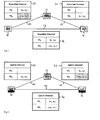
- FIG. 1 shows transmission on the downlink in accordance with the present invention.
- a base station BS 10 transmits a downlink signal which is received by a relay node RN 12 as downlink signal 20 and by a user terminal UT 14 as downlink signal 24.
- RN 12 also transmits a downlink signal 22 which is received by UT 14.
- Tables 30, 32, and 34 show the contents of downlink signals 20, 22 and 24 respectively.
- Each signal comprises two downlink channels - timeslot TS 1 and timeslot TS 2 .
- the contents of downlink signals 20 and 24 transmitted from BS 10 comprise two symbols (s 1 , s 2 ) in TS 1 and a function of the two symbols (-s 2 *, s 1 *) in TS 2 (where x* represents the complex conjugate of x). If these symbols (s 1 , s 2 ) and (-s 2 *, s 1 *) were transmitted in the same downlink channel (e.g., in TS 1 ) from two separate antennas of the base station for reception at a single antenna of a user terminal they would together form an Alamouti STBC as known in the art.
- RN 12 transmits using two separate downlink channels - timeslot TS 1 and timeslot TS 2 , and optionally from a single antenna of the base station.
- TS 2 are "greyed out" in table 30 to indicate that although the signal is transmitted from BS 10 it is not necessarily received by RN 12.
- the RN typically cannot receive in TS 2 because according to the present invention it is transmitting on the same channel.
- the contents of downlink signal 22 transmitted from RN 12 comprise (s 1 , s 2 ) in TS 2 - i.e. the same as the contents of TS 1 in downlink signal 20.
- RN 12 stores the signal (s 1 , s 2 ) received from BS 10 on TS 1 for one TS and transmits it to UT 14 in TS 2 .
- the BS and RN transmissions 22 and 24 received at UT 14 in TS 2 together form an Alamouti STBC which is decoded at the UT.
- the extra information contained in TS 1 from BS 10 enables 3-branch diversity at the UT.
- the UT stores it for one TS and combines it with the Alamouti code.
- the UT cannot decode Alamouti STBCs, then the BS will not transmit in TS 2 .
- Figure 2 shows transmission on the uplink in accordance with the present invention.
- UT 14 transmits an uplink signal which is received by RN 12 as uplink signal 42 and by BS 10 as uplink signal 44.
- RN 12 also transmits an uplink signal 40 which is received by UT 14.
- Tables 50, 52, and 54 show the contents of uplink signals 40, 42 and 44 respectively. Each signal comprises two uplink channels - timeslot TS 1 and timeslot TS 2 .
- uplink signals 42 and 44 transmitted from UT 14 comprise two symbols (s 1 , s 2 ) in TS 1 and a function of the two symbols (-s 2 *, s 1 *) in TS 2 (where x* represents the complex conjugate of x). If these symbols (s 1 , s 2 ) and (-s 2 *, s 1 *) were transmitted in the same uplink channel from two separate antennas of the user terminal for reception at a single antenna of a base station, they would together form an Alamouti STBC as known in the art. However, in the present invention, they are transmitted using two separate uplink channels - timeslot TS 1 and timeslot TS 2 , and optionally from a single antenna of the user terminal.
- TS 2 contents of TS 2 are "greyed out" in table 42 to indicate that although the signal is transmitted from UT 14 it is not necessarily received by RN 12.
- the RN typically cannot receive in TS 2 because according to the present invention it is transmitting on the same channel.
- the contents of uplink signal 40 transmitted from RN 12 comprise (s 1 , s 2 ) in TS 2 - i.e. the same as contents of TS 1 in uplink signal 42.
- RN 12 stores the signal (s 1 , s 2 ) received from UT 14 on TS 1 for one TS and transmits it to BS 10 on TS 2 .
- the UT and RN transmissions 44 and 40 received at BS 10 in TS 2 form an Alamouti STBC which is decoded at the UT.
- the extra information contained in TS 1 from UT 14 enables 3-branch diversity at the BS.
- the BS stores it for one TS and combines it with the Alamouti code.
- downlink is BS to UT
- uplink is UT to BS.
- Downlink and uplink channels may be different frequencies in a Frequency Division Duplex system (FDD) or time periods in a Time Division Duplex system (TDD). While embodiments described in this document have shown how uplink and downlink channels are provided using two timeslots or frequencies each having two symbols to provide space time block coding in a co-operative relaying scheme, it will be apparent to one skilled in the art that any orthogonal channels may be used for each set of symbols provided that the channel on which the relay node transmits a set of symbols is later in time than the channel on which it receives that set of symbols.
- channels may be orthogonal in time, frequency, spreading code or any combination of the same provided that the channel on which the relay node transmits a set of symbols is later in time than the channel on which it receives that set of symbols.
- the function of the RN can be as repeater - i.e. a node which receives an RF downlink or uplink signal and re-transmits it without demodulation, decoding or other processing - or as a regenerator - i.e. a node which receives an RF signal, performs demodulation, decoding and/or some other digital processing on the RF signal to determine the transmitted data (after conversion to digital) and then re-generates a new RF signal using the appropriate modulation and coding using the determined data.
- the RN transmits a downlink or uplink signal representing the same data as it has received.
- the BS is not significantly changed.
- the BS transmits on the downlink channel and receives on the uplink channel.
- the BS must store the signal received from the UT in TS 1 for one TS and combine it with the signal received from the RN in TS 2 as well as decoding the STBC in order to gain full advantage of the available diversity.
- the UT is relatively simple. According to the downlink and uplink transmission schemes above, the UT transmits on the uplink channel, as it would for a direct transmission to a BS. It receives on the downlink channel, as it would for direct reception from a BS.
- the UT must be able to decode Alamouti STBCs in order to obtain the additional diversity, but this is optional. It may also combine signals from both timeslots for extra diversity if memory is available.
- the RN is more complex. According to the downlink and uplink transmission scheme above, the RN must transmit on both the downlink and uplink channels. The RN must receive on both the downlink and uplink channels. It may need to transmit and receive simultaneously.
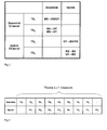
- FIG 3 shows timeslot usage in uplink and downlink in accordance with the present invention.
- Four timeslots are available: TS 1 and TS 2 on the downlink channel; TS 1 and TS 2 on the uplink channel.
- Two timeslots worth of data are received: one by the UT on the downlink (downlink channel TS 2 ); one by the BS on the uplink (uplink channel TS 2 ).
- the advantage is that both the UT and the BS are relatively unchanged from a conventional system.
- Only the RN needs to transmit and receive on both the uplink and the downlink channels.
- the RN is transmitting on the uplink and downlink channels in the same TS, namely TS2, (i.e., simultaneously in a FDD system. In a TDD system, TS 1 and TS2 of the downlink channel would be separated in time from TS 1 and TS2 of the uplink channel).
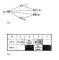
- Figure 5 shows a scenario for interleaving transmissions to two user terminals in accordance with the present invention
- Figure 6 shows downlink transmissions in the scenario for interleaving transmissions to two user terminals in accordance with the present invention.
- the RN is required to receive on TS 1 and transmit on TS 2 . This may be difficult to achieve in practice in a digital system as it leaves no time for processing the received signal.
- transmissions from BS 68 to two (or more) UTs 60, 62 using two (or more) RNs 64, 66 are interleaved so that there is a one TS gap of between reception and transmission at each RN (see figure 5 and figure 6).
- multihop diversity or cooperative relaying, combines the signals from a source (e.g., base station) and a relay at a destination (e.g., user terminal).
- a source e.g., base station
- a destination e.g., user terminal
- the source and destination may be a base station or user terminal, in three or more hop scenarios, the source and/or the destination may themselves be further relay nodes between a base station and user terminal.
- uplink and downlink transmission schemes utilizing STBC and multihop diversity applies generally to transmissions from any source (on the downlink a base station or a relay node, and on the uplink a relay node or user terminal) to any destination (correspondingly on the downlink a user terminal or relay node, and on the uplink a relay node or base station) using a relay node.
- Different STBCs may be used for uplink or downlink communications and for different two-hop stages of the uplink and downlink in three or more hop scenarios.
- the STBC used for downlink by the base station may be different to the STBC used for uplink by the user terminal.
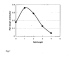
- Figure 7 shows a graph of an example of a distribution of path lengths for routing, path selection and scheduling in accordance with the present invention (0 represents UTs out of coverage; 1 is the direct path between the BS and the UT). Routing algorithms are generally too slow to react to Rayleigh fading and so path selection must be based on path loss due to distance and lognormal shadowing. Advantage may be taken of multiuser diversity by scheduling to each user depending on the total path loss, including Rayleigh fading, at any given time; however, the number of simultaneous users may be restricted at the high data rates for which use of multihop is proposed as a coverage enhancement mechanism, thus restricting the diversity benefit.
- Multihop paths should only be used if the existing direct path is incapable of providing sufficient signal quality; furthermore, longer multihop paths (>2 hops) should only be used if shorter paths are incapable of providing sufficient signal quality. What is deemed sufficient may be determined by the desire to maximise coverage or capacity or minimise delay, etc. We therefore propose that a quality metric is fed back from the destination into the path selection algorithm, whether this is centralised (source routed) or distributed and that this be used to optimise path selection. Our preferred metric is SINR at the destination, though other metrics can be envisaged.
- Multihop paths provide higher SINRs than direct paths in many instances and so a multihop network can provide better coverage than a conventional cellular network.
- longer multihop paths increase latency and multihop proposals often restrict path lengths to 2 hops.
- Figure 7 proposes a scheduler which is sensitive to path length such that it gives a higher priority to longer paths, thus reducing the combined scheduling delay on such paths and hence reducing the delay spread in a multihop network. Because the longer paths are only used occasionally (Figure 7), the overall increase in average delay is small and, consequently, so is the impact on the direct and shorter paths.
Landscapes
- Engineering & Computer Science (AREA)
- Signal Processing (AREA)
- Computer Networks & Wireless Communication (AREA)
- Mobile Radio Communication Systems (AREA)
- Radio Transmission System (AREA)
Abstract
Description
- The present invention relates to methods, systems and apparatuses for transmitting and receiving space-time block coded data in a wireless communications system with cooperative relays.
- In a conventional cellular wireless system, a base station communicates directly with a user terminal. If two antennas are available at the base station, a space time block code (STBC), such as an Alamouti STBC, may be used to obtain diversity gain, thus improving the quality of the received signal. A multihop network differs from a conventional cellular network in that one or more relays may be included in the path between a base station and a user terminal. Multihop diversity, sometimes known as cooperative relaying, combines the signals from the source (e.g., base station) and a relay at the destination (e.g., user terminal) to improve the quality of the received signal. The purpose of a multihop system is to enhance the signal quality at the destination (base station on the uplink and user terminal on the downlink) in comparison with a conventional cellular wireless system.
- A number of alternative cooperative relaying schemes have been proposed but these involve multiple relays acting in parallel in each path, which means more relays are required, resulting in a higher network cost. Space time coding has also been proposed for use with multihop systems but schemes known to the author involve multiple antennas at the base station and the relays, and sometimes at the user terminal as well. While the use of multiple antennas at the base station is practical, multiple antennas at the relay would mitigate against many deployment options which are attractive for other reasons (e.g., cost of deployment, access to sites, etc.). The use of multiple antennas at the user terminal is something that terminal manufacturers have resisted in their efforts to reduce cost and size of the terminal.
- This invention describes a method of employing STBCs, such as Alamouti STBCs, in combination with cooperative relaying in a multihop network to further improve the quality of the received signal. This invention provides for a further enhancement of the received signal quality in an efficient manner requiring minimum complexity in the respective nodes. This means that fewer relays are required for a given performance, thus reducing the overall cost of the network. Only one antenna is required at each node (i.e., base station, relay and user terminal) although extension to multiple antennas is possible. The invention also describes an efficient method of arranging the transmissions of the various nodes (base station, relay and user terminal) to avoid violating causality and to provide adequate time for each node to process the received signals in an efficient manner.
- According to a first aspect of the present invention there is provided a method of transmitting data using a space-time block code in a wireless communications system comprising a source node and a relay node, the method comprising:
- the source node transmitting RF signals representing first and second sets of data symbols in respective first and second channels of the wireless communications system, the first and second sets of data symbols being for transmission from separate antennas respectively according to the space-time block code; and
- the relay node receiving the RF signals representing the first set of data symbols in the first channel and transmitting RF signals representing the first set of data symbols in the second channel.
- According to a second aspect of the present invention there is provided a wireless communications system using a space-time block code for transmissions, the system comprising:
- a source node arranged to transmit RF signals representing first and second sets of data symbols in respective first and second channels of the wireless communications system, the first and second sets of data symbols being for transmission from separate antennas respectively according to the space-time block code; and
- a relay node arranged to receive the RF signals representing the first set of data symbols in the first channel and to transmit RF signals representing the first set of data symbols in the second channel.
- According to a third aspect of the present invention there is provided a method of transmitting data using a space-time block code in a wireless communications system comprising a source node, the method comprising:
- the source node transmitting RF signals representing first and second sets of data symbols in respective first and second channels of the wireless communications system, the first and second sets of data symbols being for transmission from separate antennas respectively according to the space-time block code.
- According to a fourth aspect of the present invention there is provided a source node for use in a wireless communications system for transmitting data using a space-time block code, the source node being arranged to transmit RF signals representing first and second sets of data symbols in respective first and second channels of the wireless communications system, the first and second sets of data symbols being for transmission from separate antennas respectively according to the space-time block code.
- According to a fifth aspect of the present invention there is provided a method of transmitting data using a space-time block code in a wireless communications system comprising a relay node, the method comprising:
- the relay node receiving RF signals representing a first set of data symbols in a first channel of the wireless communications system; and
- the relay node transmitting RF signals representing the first set of data symbols in a second channel of the wireless communications system;
- According to a sixth aspect of the present invention there is provided a relay node for use in a wireless communications system for transmitting data using a space-time block code, the relay node being arranged to receive RF signals representing a first set of data symbols in a first channel of the wireless communications system and to transmit RF signals representing the first set of data symbols in a second channel of the wireless communications system,
wherein the second channel of the wireless communications system is for transmission of a second set of data symbols, the first and second sets of data symbols being for transmission from separate antennas respectively according to the space-time block code. - The invention to be described herein affords several advantages. The base station (BS) only needs to transmit on the "downlink" channel and receive on the "uplink" channel. The relay is only required to transmit on the "downlink" channel and to receive on the "uplink" channel, although it may need to do so simultaneously in some embodiments in an FDD system. The RN (relay node) is therefore very simple and potentially inexpensive. The user terminal (UT) is only required to transmit on the "uplink" channel and to receive on the "downlink" channel, although it may need to do so simultaneously in some embodiments in an FDD system. The most significant modification in practical products is to enable the UT and BS to decode Alamouti STBCs and optionally to store and subsequently combine signals from the BS and UT respectively with those from the RN, providing additional diversity; however, this is optional and so UTs that do not have this capability are not excluded from the system.
- There now follows, by way of example only, a detailed description of preferred embodiments of the present invention in which:
-
- Figure 1 shows transmission on the downlink in accordance with the present invention;
- Figure 2 shows transmission on the uplink in accordance with the present invention;
- Figure 3 shows timeslot usage in uplink and downlink in accordance with the present invention;
- Figure 4 shows a frame structure for staggering uplink and downlink transmission in accordance with the present invention;
- Figure 5 shows a scenario for interleaving transmissions to two user terminals in accordance with the present invention;
- Figure 6 shows downlink transmissions in the scenario for interleaving transmissions to two user terminals in accordance with the present invention; and
- Figure 7 shows a graph of a distribution of path lengths for routing, path selection and scheduling in accordance with the present invention.
- The following is a description of the best mode of practicing the invention known to the inventor.
- Figure 1 shows transmission on the downlink in accordance with the present invention.
A base station BS 10 transmits a downlink signal which is received by arelay node RN 12 as downlink signal 20 and by auser terminal UT 14 asdownlink signal 24.RN 12 also transmits adownlink signal 22 which is received by UT 14. Tables 30, 32, and 34 show the contents ofdownlink signals - The contents of
downlink signals 20 and 24 transmitted fromBS 10 comprise two symbols (s1, s2) in TS1 and a function of the two symbols (-s2*, s1*) in TS2 (where x* represents the complex conjugate of x). If these symbols (s1, s2) and (-s2*, s1*) were transmitted in the same downlink channel (e.g., in TS1) from two separate antennas of the base station for reception at a single antenna of a user terminal they would together form an Alamouti STBC as known in the art. However, in the present invention, they are transmitted using two separate downlink channels - timeslot TS1 and timeslot TS2, and optionally from a single antenna of the base station. Note the contents of TS2 are "greyed out" in table 30 to indicate that although the signal is transmitted fromBS 10 it is not necessarily received byRN 12. The RN typically cannot receive in TS2 because according to the present invention it is transmitting on the same channel. The contents ofdownlink signal 22 transmitted fromRN 12 comprise (s1, s2) in TS2 - i.e. the same as the contents of TS1 in downlink signal 20. Thus,RN 12 stores the signal (s1, s2) received fromBS 10 on TS1 for one TS and transmits it toUT 14 in TS2. - The BS and
RN transmissions UT 14 in TS2 together form an Alamouti STBC which is decoded at the UT. The extra information contained in TS1 fromBS 10 enables 3-branch diversity at the UT. The UT stores it for one TS and combines it with the Alamouti code. This may be done through i) addition of the received RF signals at baseband, ii) apportionment of the received RF signals at baseband, iii) selection between the received RF signals at baseband according to a measure of signal quality; iv) demodulation of the received RF signals into demodulated RF signals followed by combination of the demodulated RF signals (by simple addition thereof, apportionment thereof or selection there between), or by demodulation and decoding of the received RF signals into data symbols followed by combination of the decoded data symbols. In case the UT cannot decode Alamouti STBCs, then the BS will not transmit in TS2. - Figure 2 shows transmission on the uplink in accordance with the present invention.
UT 14 transmits an uplink signal which is received byRN 12 asuplink signal 42 and byBS 10 asuplink signal 44.RN 12 also transmits anuplink signal 40 which is received byUT 14. Tables 50, 52, and 54 show the contents of uplink signals 40, 42 and 44 respectively. Each signal comprises two uplink channels - timeslot TS1 and timeslot TS2. - The contents of uplink signals 42 and 44 transmitted from
UT 14 comprise two symbols (s1, s2) in TS1 and a function of the two symbols (-s2*, s1*) in TS2 (where x* represents the complex conjugate of x). If these symbols (s1, s2) and (-s2*, s1*) were transmitted in the same uplink channel from two separate antennas of the user terminal for reception at a single antenna of a base station, they would together form an Alamouti STBC as known in the art. However, in the present invention, they are transmitted using two separate uplink channels - timeslot TS1 and timeslot TS2, and optionally from a single antenna of the user terminal. Note the contents of TS2 are "greyed out" in table 42 to indicate that although the signal is transmitted fromUT 14 it is not necessarily received byRN 12.
The RN typically cannot receive in TS2 because according to the present invention it is transmitting on the same channel. The contents ofuplink signal 40 transmitted fromRN 12 comprise (s1, s2) in TS2 - i.e. the same as contents of TS1 inuplink signal 42. Thus,RN 12 stores the signal (s1, s2) received fromUT 14 on TS1 for one TS and transmits it toBS 10 on TS2. - The UT and
RN transmissions BS 10 in TS2 form an Alamouti STBC which is decoded at the UT. The extra information contained in TS1 fromUT 14 enables 3-branch diversity at the BS. The BS stores it for one TS and combines it with the Alamouti code. This may be done through i) addition of the received RF signals at baseband, ii) apportionment of the received RF signals at baseband, iii) selection between the received RF signals at baseband according to a measure of signal quality; iv) demodulation of the received RF signals into demodulated RF signals followed by combination of the demodulated RF signals (by simple addition thereof, apportionment thereof or selection there between), or by demodulation and decoding of the received RF signals into data symbols followed by combination of the decoded data symbols. - Note in the above, downlink is BS to UT, uplink is UT to BS. Downlink and uplink channels may be different frequencies in a Frequency Division Duplex system (FDD) or time periods in a Time Division Duplex system (TDD). While embodiments described in this document have shown how uplink and downlink channels are provided using two timeslots or frequencies each having two symbols to provide space time block coding in a co-operative relaying scheme, it will be apparent to one skilled in the art that any orthogonal channels may be used for each set of symbols provided that the channel on which the relay node transmits a set of symbols is later in time than the channel on which it receives that set of symbols. For example, channels may be orthogonal in time, frequency, spreading code or any combination of the same provided that the channel on which the relay node transmits a set of symbols is later in time than the channel on which it receives that set of symbols.
- Also note in the above that the function of the RN can be as repeater - i.e. a node which receives an RF downlink or uplink signal and re-transmits it without demodulation, decoding or other processing - or as a regenerator - i.e. a node which receives an RF signal, performs demodulation, decoding and/or some other digital processing on the RF signal to determine the transmitted data (after conversion to digital) and then re-generates a new RF signal using the appropriate modulation and coding using the determined data. In either case, as described above, the RN transmits a downlink or uplink signal representing the same data as it has received.
- As can be seen from the description of downlink and uplink transmission schemes above, the BS is not significantly changed. The BS transmits on the downlink channel and receives on the uplink channel. However, the BS must store the signal received from the UT in TS1 for one TS and combine it with the signal received from the RN in TS2 as well as decoding the STBC in order to gain full advantage of the available diversity.
- The UT is relatively simple. According to the downlink and uplink transmission schemes above, the UT transmits on the uplink channel, as it would for a direct transmission to a BS. It receives on the downlink channel, as it would for direct reception from a BS. The UT must be able to decode Alamouti STBCs in order to obtain the additional diversity, but this is optional. It may also combine signals from both timeslots for extra diversity if memory is available.
- The RN is more complex. According to the downlink and uplink transmission scheme above, the RN must transmit on both the downlink and uplink channels. The RN must receive on both the downlink and uplink channels. It may need to transmit and receive simultaneously.
- Figure 3 shows timeslot usage in uplink and downlink in accordance with the present invention. Four timeslots are available: TS1 and TS2 on the downlink channel; TS1 and TS2 on the uplink channel. Two timeslots worth of data are received: one by the UT on the downlink (downlink channel TS2); one by the BS on the uplink (uplink channel TS2). Efficiency is therefore 2/4 = ½. The advantage is that both the UT and the BS are relatively unchanged from a conventional system. Only the RN needs to transmit and receive on both the uplink and the downlink channels. The RN is transmitting on the uplink and downlink channels in the same TS, namely TS2, (i.e., simultaneously in a FDD system. In a TDD system,
TS 1 and TS2 of the downlink channel would be separated in time fromTS 1 and TS2 of the uplink channel). - To avoid this problem, we optionally slip the uplink relative to the downlink by one TS, which has a limited effect on efficiency if the frame length is many TSs (as shown in Figure 4), or use different RNs for uplink and downlink. Staggering uplink and downlink timeslots means that a RN does not have to transmit on both uplink and downlink channels at the same time in an FDD system. The efficiency is degraded slightly by this slippage in the uplink TS:

- Figure 5 shows a scenario for interleaving transmissions to two user terminals in accordance with the present invention and Figure 6 shows downlink transmissions in the scenario for interleaving transmissions to two user terminals in accordance with the present invention. According to the downlink and uplink transmission scheme above, the RN is required to receive on TS1 and transmit on TS2. This may be difficult to achieve in practice in a digital system as it leaves no time for processing the received signal. To overcome this problem, transmissions from
BS 68 to two (or more) UTs 60, 62 using two (or more)RNs - As stated above, multihop diversity, or cooperative relaying, combines the signals from a source (e.g., base station) and a relay at a destination (e.g., user terminal). It will be apparent to one skilled in the art that while, in two hop scenarios, the source and destination may be a base station or user terminal, in three or more hop scenarios, the source and/or the destination may themselves be further relay nodes between a base station and user terminal. Thus, it will be appreciated that the above description of uplink and downlink transmission schemes utilizing STBC and multihop diversity according to the present invention applies generally to transmissions from any source (on the downlink a base station or a relay node, and on the uplink a relay node or user terminal) to any destination (correspondingly on the downlink a user terminal or relay node, and on the uplink a relay node or base station) using a relay node.
- Different STBCs may be used for uplink or downlink communications and for different two-hop stages of the uplink and downlink in three or more hop scenarios. For example, the STBC used for downlink by the base station may be different to the STBC used for uplink by the user terminal.
- Figure 7 shows a graph of an example of a distribution of path lengths for routing, path selection and scheduling in accordance with the present invention (0 represents UTs out of coverage; 1 is the direct path between the BS and the UT). Routing algorithms are generally too slow to react to Rayleigh fading and so path selection must be based on path loss due to distance and lognormal shadowing. Advantage may be taken of multiuser diversity by scheduling to each user depending on the total path loss, including Rayleigh fading, at any given time; however, the number of simultaneous users may be restricted at the high data rates for which use of multihop is proposed as a coverage enhancement mechanism, thus restricting the diversity benefit.
- It is proposed that greater diversity benefit can be obtained by combining multihop routing and scheduling as follows: For each UT, several multihop paths are found and stored (instead of just one) and these are updated on a timescale determined by the change in average path loss, which is predominantly due to changes in lognormal shadowing. Packets may be scheduled across any one of these paths to any one of the several users determined by the combination of the path loss due to distance, lognormal shadowing and Rayleigh fading on each path. Thus the degree of diversity is increased and advantage can be taken of the Rayleigh up fades to improve throughput.
- Multihop paths should only be used if the existing direct path is incapable of providing sufficient signal quality; furthermore, longer multihop paths (>2 hops) should only be used if shorter paths are incapable of providing sufficient signal quality. What is deemed sufficient may be determined by the desire to maximise coverage or capacity or minimise delay, etc. We therefore propose that a quality metric is fed back from the destination into the path selection algorithm, whether this is centralised (source routed) or distributed and that this be used to optimise path selection. Our preferred metric is SINR at the destination, though other metrics can be envisaged.
- Multihop paths provide higher SINRs than direct paths in many instances and so a multihop network can provide better coverage than a conventional cellular network. However, longer multihop paths increase latency and multihop proposals often restrict path lengths to 2 hops. We note, however, that where longer paths are allowed, they are only used a small percentage of the time (Figure 7) and that the higher SINR provided by them results in a higher bit rate to further reduce the time required. We therefore propose a scheduler which is sensitive to path length such that it gives a higher priority to longer paths, thus reducing the combined scheduling delay on such paths and hence reducing the delay spread in a multihop network. Because the longer paths are only used occasionally (Figure 7), the overall increase in average delay is small and, consequently, so is the impact on the direct and shorter paths.
Claims (40)
- A method of transmitting data using a space-time block code in a wireless communications system comprising a source node and a relay node, the method comprising:the source node transmitting RF signals representing first and second sets of data symbols in respective first and second channels of the wireless communications system, the first and second sets of data symbols being for transmission from separate antennas respectively according to the space-time block code; andthe relay node receiving the RF signals representing the first set of data symbols in the first channel and transmitting RF signals representing the first set of data symbols in the second channel.
- A method according to claim 1, wherein the wireless communications system comprises a destination node, the method comprising:the destination node receiving the RF signals representing the second set of data symbols from the source node and the RF signals representing the first set of data symbols from the relay node, thereby enabling decoding of the received RF signals representing the first and second sets of data symbols according to the space-time block code.
- A method according to claim 1, wherein the source node transmits RF signals representing the first and second sets of data symbols from a single antenna.
- A method according to claim 2, wherein the destination node receives the RF signals representing the first and second sets of data symbols at a single antenna.
- A method according to claim 1, wherein the first and second channels are ones selected from the group comprising: first and second timeslots of a frame structure of the wireless communications system; first and second frequencies of a frame structure of the wireless communications system and first and second spreading codes of a frame structure of the wireless communications system, provided in each case that the second channel is later in time than the first channel.
- A method according to claim 2 comprising:the destination node receiving RF signals representing the first set of data symbols from the source node; andcombining the RF signals representing first set of data symbols from the source node with RF signals representing the second set of data symbols from the source node and the RF signals representing the first set of data symbols from the relay node.
- A method according to claim 2, comprising
the destination node transmitting RF signals representing third and fourth sets of data symbols in respective third and fourth channels of the wireless communications system, the third and fourth sets of data symbols being for transmission from separate antennas respectively according to a space-time block code;
the relay node receiving the RF signals representing the third set of data symbols in the third channel and transmitting RF signals representing the third set of data symbols in the fourth channel;
the source node receiving RF signals representing the fourth sets of data symbols from the destination node and RF signals representing the third set of data symbols from the relay node, thereby enabling decoding of the received RF signals representing the third and fourth sets of data symbols according to the space-time block code. - A method according to claim 7, wherein the second and fourth channels are staggered in time such that the relay node does not transmit the first and third set of data symbols simultaneously.
- A method according to claim 1, wherein the wireless communications system comprises a second relay node, the method comprising:the source node transmitting RF signals representing fifth and sixth sets of data symbols in respective fifth and sixth channels of the wireless communications system, the fifth and sixth sets of data symbols being for transmission from separate antennas respectively according to the space-time block code; andthe second relay node receiving the RF signals representing the fifth set of data symbols in the fifth channel and transmitting RF signals representing the fifth set of data symbols in the sixth channel;wherein the first and second channels and fifth and sixth channels are interleaved in time such that the relay node has time to process the RF signals representing the first and fifth set of data symbols before transmitting RF signals representing the first and fifth set of data symbols in the second and sixth channel.
- A method according to claim 1, wherein the space-time block code is an Alamouti space-time block code.
- A method according to claim 1, wherein the source node is one selected from the group comprising: a base station, another relay node, and a user terminal.
- A method according to claim 2, wherein the destination node is one selected from the group comprising: a base station, another relay node, and a user terminal.
- A wireless communications system using a space-time block code for transmissions, the system comprising:a source node arranged to transmit RF signals representing first and second sets of data symbols in respective first and second channels of the wireless communications system, the first and second sets of data symbols being for transmission from separate antennas respectively according to the space-time block code; anda relay node arranged to receive the RF signals representing the first set of data symbols in the first channel and to transmit RF signals representing the first set of data symbols in the second channel.
- A wireless communications system according to claim 13, comprising:a destination node arranged to receive the RF signals representing the second set of data symbols from the source node and the RF signals representing the first set of data symbols from the relay node, thereby enabling decoding of the received RF signals representing the first and second sets of data symbols according to the space-time block code.
- A wireless communications system according to claim 13, wherein the source node is arranged to transmit RF signals representing the first and second sets of data symbols from a single antenna.
- A wireless communications system according to claim 14, wherein the destination node is arranged to receive the RF signals representing the first and second sets of data symbols at a single antenna.
- A wireless communications system according to claim 13 wherein the first and second channels are ones selected from the group comprising: first and second timeslots of a frame structure of the wireless communications system; first and second frequencies of a frame structure of the wireless communications system and first and second spreading codes of a frame structure of the wireless communications system, provided in each case that the second channel is later in time than the first channel.
- A wireless communications system according to claim 14 wherein the destination node is arranged to receive RF signals representing the first set of data symbols from the source node and to combine the RF signals representing first set of data symbols from the source node with RF signals representing the second set of data symbols from the source node and the RF signals representing the first set of data symbols from the relay node.
- A wireless communications system according to claim 14,
wherein the destination node is arranged to transmit RF signals representing third and fourth sets of data symbols in respective third and fourth channels of the wireless communications system, the third and fourth sets of data symbols being for transmission from separate antennas respectively according to a space-time block code;
wherein the relay node is arranged to receive the RF signals representing the third set of data symbols in the third channel and to transmit RF signals representing the third set of data symbols in the fourth channel; and
wherein the source node is arranged to receive RF signals representing the fourth sets of data symbols from the destination node and RF signals representing the third set of data symbols from the relay node, thereby enabling decoding of the received RF signals representing the third and fourth sets of data symbols according to the space-time block code. - A wireless communications system according to claim 19, wherein the second and fourth channels are staggered in time such that the relay node does not transmit the first and third set of data symbols simultaneously.
- A wireless communications system according to claim 13 comprising a second relay node,
wherein the source node is arranged to transmit RF signals representing fifth and sixth sets of data symbols in respective fifth and sixth channels of the wireless communications system, the fifth and sixth sets of data symbols being for transmission from separate antennas respectively according to the space-time block code;
wherein the second relay node is arranged to receive the RF signals representing the fifth set of data symbols in the fifth channel and to transmit RF signals representing the fifth set of data symbols in the sixth channel; and
wherein the first and second channels and fifth and sixth channels are interleaved in time such that the relay node has time to process the RF signals representing the first and fifth set of data symbols before transmitting RF signals representing the first and fifth set of data symbols in the second and sixth channel. - A wireless communications system according to claim 13, wherein the space-time block code is an Alamouti space-time block code.
- A wireless communications system according to claim 13, wherein the source node is one selected from the group comprising: a base station, another relay node, and a user terminal.
- A wireless communications system according to claim 14, wherein the destination node is one selected from the group comprising: a base station, another relay node, and a user terminal.
- A method of transmitting data using a space-time block code in a wireless communications system comprising a source node, the method comprising:the source node transmitting RF signals representing first and second sets of data symbols in respective first and second channels of the wireless communications system, the first and second sets of data symbols being for transmission from separate antennas respectively according to the space-time block code.
- A method according to claim 25, wherein the source node transmits RF signals representing the first and second sets of data symbols from a single antenna.
- A method according to claim 25, wherein the first and second channels are ones selected from the group comprising: first and second timeslots of a frame structure of the wireless communications system; first and second frequencies of a frame structure of the wireless communications system and first and second spreading codes of a frame structure of the wireless communications system, provided in each case that the second channel is later in time than the first channel.
- A method according to claim 25, wherein the space-time block code is an Alamouti space-time block code.
- A method according to claim 25, wherein the source node is one selected from the group comprising: a base station, a relay node, and a user terminal.
- A source node for use in a wireless communications system for transmitting data using a space-time block code, the source node being arranged to transmit RF signals representing first and second sets of data symbols in respective first and second channels of the wireless communications system, the first and second sets of data symbols being for transmission from separate antennas respectively according to the space-time block code.
- A source node according to claim 30, arranged to transmit the RF signals representing the first and second sets of data symbols from a single antenna.
- A source node according to claim 30, wherein the first and second channels are ones selected from the group comprising: first and second timeslots of a frame structure of the wireless communications system; first and second frequencies of a frame structure of the wireless communications system and first and second spreading codes of a frame structure of the wireless communications system, provided in each case that the second channel is later in time than the first channel.
- A source node according to claim 30, wherein the space-time block code is an Alamouti space-time block code.
- A source node according to claim 30, wherein the source node is one selected from the group comprising: a base station, another relay node, and a user terminal.
- A method of transmitting data using a space-time block code in a wireless communications system comprising a relay node, the method comprising:the relay node receiving RF signals representing a first set of data symbols in a first channel of the wireless communications system; andthe relay node transmitting RF signals representing the first set of data symbols in a second channel of the wireless communications system;wherein the second channel of the wireless communications system is for transmission of a second set of data symbols, the first and second sets of data symbols being for transmission from separate antennas respectively according to the space-time block code.
- A method according to claim 35, wherein the first and second channels are ones selected from the group comprising: first and second timeslots of a frame structure of the wireless communications system; first and second frequencies of a frame structure of the wireless communications system and first and second spreading codes of a frame structure of the wireless communications system, provided in each case that the second channel is later in time than the first channel.
- A method according to claim 35, wherein the space-time block code is an Alamouti space-time block code.
- A relay node for use in a wireless communications system for transmitting data using a space-time block code, the relay node being arranged to receive RF signals representing a first set of data symbols in a first channel of the wireless communications system and to transmit RF signals representing the first set of data symbols in a second channel of the wireless communications system,
wherein the second channel of the wireless communications system is for transmission of a second set of data symbols, the first and second sets of data symbols being for transmission from separate antennas respectively according to the space-time block code. - A relay node according to claim 38, wherein the first and second channels are ones selected from the group comprising: first and second timeslots of a frame structure of the wireless communications system; first and second frequencies of a frame structure of the wireless communications system and first and second spreading codes of a frame structure of the wireless communications system, provided in each case that the second channel is later in time than the first channel.
- A relay node according to claim 38, wherein the space-time block code is an Alamouti space-time block code.
Priority Applications (1)
| Application Number | Priority Date | Filing Date | Title |
|---|---|---|---|
| EP12188386.2A EP2547028A3 (en) | 2006-07-28 | 2007-07-27 | Space-time block code communications with co-operative relays |
Applications Claiming Priority (1)
| Application Number | Priority Date | Filing Date | Title |
|---|---|---|---|
| US83423106P | 2006-07-28 | 2006-07-28 |
Publications (2)
| Publication Number | Publication Date |
|---|---|
| EP1883178A2 true EP1883178A2 (en) | 2008-01-30 |
| EP1883178A3 EP1883178A3 (en) | 2011-11-30 |
Family
ID=38695504
Family Applications (2)
| Application Number | Title | Priority Date | Filing Date |
|---|---|---|---|
| EP12188386.2A Withdrawn EP2547028A3 (en) | 2006-07-28 | 2007-07-27 | Space-time block code communications with co-operative relays |
| EP07252971A Withdrawn EP1883178A3 (en) | 2006-07-28 | 2007-07-27 | Space time block code communications with co-operative relays |
Family Applications Before (1)
| Application Number | Title | Priority Date | Filing Date |
|---|---|---|---|
| EP12188386.2A Withdrawn EP2547028A3 (en) | 2006-07-28 | 2007-07-27 | Space-time block code communications with co-operative relays |
Country Status (2)
| Country | Link |
|---|---|
| US (3) | US8477677B2 (en) |
| EP (2) | EP2547028A3 (en) |
Cited By (13)
| Publication number | Priority date | Publication date | Assignee | Title |
|---|---|---|---|---|
| WO2010049427A1 (en) * | 2008-10-28 | 2010-05-06 | Nortel Networks Limited | Transferring data in a mobile telephony network |
| WO2010077421A1 (en) * | 2008-12-17 | 2010-07-08 | Research In Motion Limited | Apparatus and method for autonomous combining in a wireless relay network |
| WO2010078772A1 (en) * | 2009-01-07 | 2010-07-15 | 中兴通讯股份有限公司 | Space time coding method in orthogonal network and relay transmission system |
| WO2010124420A1 (en) * | 2009-04-28 | 2010-11-04 | 上海贝尔股份有限公司 | Method and network entity for enabling user terminals to demodulate data correctly |
| US20100296433A1 (en) * | 2009-05-20 | 2010-11-25 | Jong-Seon No | Source antenna switching scheme for non-orthogonal protocol |
| KR20110082523A (en) * | 2008-11-05 | 2011-07-19 | 엘지전자 주식회사 | Repeater frame structure to support transparent and bidirectional repeaters |
| US8265128B2 (en) | 2008-12-19 | 2012-09-11 | Research In Motion Limited | Multiple-input multiple-output (MIMO) with relay nodes |
| US8311061B2 (en) | 2008-12-17 | 2012-11-13 | Research In Motion Limited | System and method for multi-user multiplexing |
| US8335466B2 (en) | 2008-12-19 | 2012-12-18 | Research In Motion Limited | System and method for resource allocation |
| US8355388B2 (en) | 2008-12-17 | 2013-01-15 | Research In Motion Limited | System and method for initial access to relays |
| US8402334B2 (en) | 2008-12-17 | 2013-03-19 | Research In Motion Limited | System and method for hybrid automatic repeat request (HARQ) functionality in a relay node |
| US8446856B2 (en) | 2008-12-19 | 2013-05-21 | Research In Motion Limited | System and method for relay node selection |
| US8848594B2 (en) | 2008-12-10 | 2014-09-30 | Blackberry Limited | Method and apparatus for discovery of relay nodes |
Families Citing this family (19)
| Publication number | Priority date | Publication date | Assignee | Title |
|---|---|---|---|---|
| WO2007114049A1 (en) * | 2006-03-29 | 2007-10-11 | Matsushita Electric Industrial Co., Ltd. | Radio transmission system, and radio station and method used for same |
| US9699688B2 (en) * | 2007-08-02 | 2017-07-04 | Qualcomm Incorporated | Method for scheduling orthogonally over multiple hops |
| US8503374B2 (en) * | 2007-08-02 | 2013-08-06 | Qualcomm Incorporated | Method for scheduling orthogonally over multiple hops |
| KR101365565B1 (en) * | 2007-08-08 | 2014-02-21 | 포항공과대학교 산학협력단 | Space frequency block code signal processing system |
| KR101400240B1 (en) * | 2007-10-18 | 2014-06-30 | 포항공과대학교 산학협력단 | System for generating space frequency block code relay signal and method thereof |
| EP2255569B1 (en) * | 2008-02-25 | 2020-04-15 | Telefonaktiebolaget LM Ericsson (publ) | Method and base station with relays in multi-user mimo systems |
| US9356688B2 (en) * | 2008-05-29 | 2016-05-31 | Futurewei Technologies, Inc. | Method and system for full duplex relaying in a wireless communication network |
| WO2010021598A1 (en) * | 2008-08-18 | 2010-02-25 | Agency For Science, Technology And Research | Cyclic prefix schemes |
| KR101576911B1 (en) * | 2008-09-11 | 2015-12-11 | 삼성전자주식회사 | Cognitive radio communication system based on cooperation signal of secondary system |
| US20100150022A1 (en) * | 2008-12-17 | 2010-06-17 | Research In Motion Corporation | System and Method for a Relay Protocol Stack |
| CN101841861B (en) * | 2009-03-18 | 2014-03-12 | 中兴通讯股份有限公司 | Method and device for receiving downlink service in long-term evolution system |
| US8838020B2 (en) * | 2011-08-31 | 2014-09-16 | Alcatel Lucent | Method for relaying data in a communication network |
| EP2605465A1 (en) * | 2011-12-16 | 2013-06-19 | Mitsubishi Electric R&D Centre Europe B.V. | Method and a device for transmitting OFDM symbols representative of plural streams |
| GB2500648B (en) * | 2012-03-28 | 2014-06-25 | Toshiba Res Europ Ltd | Wireless communication methods and apparatus |
| KR102029208B1 (en) * | 2013-06-04 | 2019-11-08 | 삼성전자주식회사 | Relay apparatus and receiving apparatus and control method thereof |
| KR102223062B1 (en) * | 2013-07-05 | 2021-03-05 | 삼성전자주식회사 | Relay apparatus and receiving apparatus and control method thereof |
| CN103746780B (en) * | 2014-01-08 | 2016-11-23 | 西安电子科技大学 | Via node based on self-information transmission rotates retransmission method |
| CN107204833B (en) * | 2017-04-11 | 2020-07-14 | 西安电子科技大学 | Decoding method of Alamouti code of time-varying channel bidirectional relay system |
| CN108551688B (en) * | 2018-03-22 | 2020-11-06 | 上海交通大学 | Multi-user scheduling method for full-duplex relay system based on power adaptation |
Family Cites Families (17)
| Publication number | Priority date | Publication date | Assignee | Title |
|---|---|---|---|---|
| US6314535B1 (en) * | 1999-05-18 | 2001-11-06 | Xircom Wireless, Inc. | Dynamic forward error correction |
| US7113745B2 (en) * | 2001-02-21 | 2006-09-26 | Ericsson Inc. | Method to achieve diversity in a communication network |
| EP1400062A2 (en) * | 2001-06-28 | 2004-03-24 | King's College London | Electronic data communication system |
| US7394754B2 (en) * | 2002-08-01 | 2008-07-01 | Mediatek Inc. | System and method for transmitting data in a multiple-branch transmitter-diversity orthogonal frequency-division multiplexing (OFDM) system |
| US7346040B2 (en) * | 2003-02-24 | 2008-03-18 | Avalonrf, Inc. | Providing a high speed data modem based on MIMO technology using a cable or single antenna |
| ATE388561T1 (en) * | 2003-05-28 | 2008-03-15 | Ericsson Telefon Ab L M | METHOD AND SYSTEM FOR WIRELESS COMMUNICATIONS NETWORKS WITH FORWARDING |
| SE0303602D0 (en) * | 2003-12-30 | 2003-12-30 | Ericsson Telefon Ab L M | Method and arrangement in self-organizing cooperative network |
| WO2005094326A2 (en) * | 2004-03-29 | 2005-10-13 | Nokia Corporation | Method and apparatus to provide power control with finite rate feedback for cooperative relay networks |
| US7265714B2 (en) * | 2004-09-23 | 2007-09-04 | Interdigital Technology Corporation | Pattern diversity to support a MIMO communications system and associated methods |
| KR100594051B1 (en) * | 2004-11-26 | 2006-06-30 | 삼성전자주식회사 | Efficient Interference Signal Cancellation Apparatus and Method in Mobile Communication Systems Supporting Multiple Transceiver Antennas |
| US20060270363A1 (en) * | 2005-05-19 | 2006-11-30 | Intel Corporation | Method and apparatus for implementing cooperative diversity using partial channel knowledge |
| KR100790359B1 (en) * | 2005-06-08 | 2008-01-02 | 한국전자통신연구원 | Spatial / Code Block Coding Transmit Diversity Apparatus, Method thereof, CDM Diversity Transmitter Using the Same, and CDMA Mobile Station Receiver |
| KR20070004370A (en) * | 2005-07-04 | 2007-01-09 | 삼성전자주식회사 | Cooperative Relay Transmission Method for Wireless Communication System |
| WO2007037714A1 (en) * | 2005-09-30 | 2007-04-05 | Intel Corporation | Systems and techniques for space-time coded cochannel interference cancellation |
| US7912147B2 (en) * | 2006-03-15 | 2011-03-22 | The Texas A&M University System | Compress-forward coding with N-PSK modulation for the half-duplex Gaussian relay channel |
| KR100998367B1 (en) * | 2009-05-20 | 2010-12-03 | 서울대학교산학협력단 | Source Antenna Switching Method of Non-Orthogonal Decoding After Transfer Protocol |
| US20120300680A1 (en) * | 2011-05-27 | 2012-11-29 | Qualcomm Incorporated | Transmission schemes for relay |
-
2007
- 2007-07-27 EP EP12188386.2A patent/EP2547028A3/en not_active Withdrawn
- 2007-07-27 EP EP07252971A patent/EP1883178A3/en not_active Withdrawn
- 2007-07-27 US US11/829,609 patent/US8477677B2/en not_active Expired - Fee Related
-
2013
- 2013-06-27 US US13/928,517 patent/US8804604B2/en not_active Expired - Fee Related
-
2014
- 2014-07-24 US US14/339,542 patent/US9294417B2/en not_active Expired - Fee Related
Non-Patent Citations (1)
| Title |
|---|
| None * |
Cited By (30)
| Publication number | Priority date | Publication date | Assignee | Title |
|---|---|---|---|---|
| WO2010049427A1 (en) * | 2008-10-28 | 2010-05-06 | Nortel Networks Limited | Transferring data in a mobile telephony network |
| KR20110082523A (en) * | 2008-11-05 | 2011-07-19 | 엘지전자 주식회사 | Repeater frame structure to support transparent and bidirectional repeaters |
| EP2319195A4 (en) * | 2008-11-05 | 2015-05-06 | Lg Electronics Inc | Relay frame structure for supporting transparent and bidirectional relays |
| US8848594B2 (en) | 2008-12-10 | 2014-09-30 | Blackberry Limited | Method and apparatus for discovery of relay nodes |
| KR101276932B1 (en) | 2008-12-17 | 2013-06-19 | 리서치 인 모션 리미티드 | Apparatus and method for autonomous combining in a wireless relay network |
| US9379804B2 (en) | 2008-12-17 | 2016-06-28 | Blackberry Limited | System and method for hybrid automatic repeat request (HARQ) functionality in a relay node |
| US8040904B2 (en) | 2008-12-17 | 2011-10-18 | Research In Motion Limited | System and method for autonomous combining |
| CN106230488B (en) * | 2008-12-17 | 2019-12-20 | 黑莓有限公司 | System and method for spontaneous merging |
| US9571179B2 (en) | 2008-12-17 | 2017-02-14 | Blackberry Limited | System and method for multi-user multiplexing |
| US8311061B2 (en) | 2008-12-17 | 2012-11-13 | Research In Motion Limited | System and method for multi-user multiplexing |
| CN106230488A (en) * | 2008-12-17 | 2016-12-14 | 黑莓有限公司 | System and method for spontaneous merging |
| US8355388B2 (en) | 2008-12-17 | 2013-01-15 | Research In Motion Limited | System and method for initial access to relays |
| US8402334B2 (en) | 2008-12-17 | 2013-03-19 | Research In Motion Limited | System and method for hybrid automatic repeat request (HARQ) functionality in a relay node |
| US9484989B2 (en) | 2008-12-17 | 2016-11-01 | Blackberry Limited | System and method for autonomous combining |
| WO2010077421A1 (en) * | 2008-12-17 | 2010-07-08 | Research In Motion Limited | Apparatus and method for autonomous combining in a wireless relay network |
| US8856607B2 (en) | 2008-12-17 | 2014-10-07 | Blackberry Limited | System and method for hybrid automatic repeat request (HARQ) functionality in a relay node |
| US8837303B2 (en) | 2008-12-17 | 2014-09-16 | Blackberry Limited | System and method for multi-user multiplexing |
| US9923628B2 (en) | 2008-12-19 | 2018-03-20 | Blackberry Limited | System and method for relay node selection |
| US8699547B2 (en) | 2008-12-19 | 2014-04-15 | Blackberry Limited | Multiple-input Multiple-output (MIMO) with relay nodes |
| US8824359B2 (en) | 2008-12-19 | 2014-09-02 | Blackberry Limited | System and method for resource allocation |
| US9191878B2 (en) | 2008-12-19 | 2015-11-17 | Blackberry Limited | System and method for relay node selection |
| US8446856B2 (en) | 2008-12-19 | 2013-05-21 | Research In Motion Limited | System and method for relay node selection |
| US8335466B2 (en) | 2008-12-19 | 2012-12-18 | Research In Motion Limited | System and method for resource allocation |
| US8265128B2 (en) | 2008-12-19 | 2012-09-11 | Research In Motion Limited | Multiple-input multiple-output (MIMO) with relay nodes |
| WO2010078772A1 (en) * | 2009-01-07 | 2010-07-15 | 中兴通讯股份有限公司 | Space time coding method in orthogonal network and relay transmission system |
| WO2010124420A1 (en) * | 2009-04-28 | 2010-11-04 | 上海贝尔股份有限公司 | Method and network entity for enabling user terminals to demodulate data correctly |
| CN102318399A (en) * | 2009-04-28 | 2012-01-11 | 上海贝尔股份有限公司 | Method and network entity for enabling user terminals to demodulate data correctly |
| CN102318399B (en) * | 2009-04-28 | 2017-03-15 | 上海贝尔股份有限公司 | Enable the user terminal correctly method of demodulating data and network entity |
| US8699400B2 (en) * | 2009-05-20 | 2014-04-15 | Snu R&Db Foundation | Source antenna switching scheme for non-orthogonal protocol |
| US20100296433A1 (en) * | 2009-05-20 | 2010-11-25 | Jong-Seon No | Source antenna switching scheme for non-orthogonal protocol |
Also Published As
| Publication number | Publication date |
|---|---|
| US20140334461A1 (en) | 2014-11-13 |
| US20130294484A1 (en) | 2013-11-07 |
| US9294417B2 (en) | 2016-03-22 |
| US20080025248A1 (en) | 2008-01-31 |
| EP2547028A3 (en) | 2013-04-10 |
| US8477677B2 (en) | 2013-07-02 |
| EP2547028A2 (en) | 2013-01-16 |
| EP1883178A3 (en) | 2011-11-30 |
| US8804604B2 (en) | 2014-08-12 |
Similar Documents
| Publication | Publication Date | Title |
|---|---|---|
| US9294417B2 (en) | Source node and relay node that cooperatively transmit an alamouti code | |
| Nomikos et al. | Hybrid NOMA/OMA with buffer-aided relay selection in cooperative networks | |
| US8831043B2 (en) | Method and system for operating cooperative receiving diversity scheme and selective cooperative relaying | |
| Host-Madsen et al. | The multiplexing gain of wireless networks | |
| EP1958345B1 (en) | Scheduling in a wireless multi-hop relay network | |
| US9130648B2 (en) | Method of and radio network for transmitting layered data to multiple receiving stations | |
| US8750788B2 (en) | Multiple data stream transmission method and apparatus in relay system | |
| US7876840B2 (en) | Wireless communication methods, systems, and signal structures | |
| CN100553228C (en) | Method for relaying data packets for downlink in wireless communication system | |
| Hoang et al. | Optimizing duration of energy harvesting for downlink NOMA full-duplex over Nakagami-m fading channel | |
| EP2301293B1 (en) | System level architectures for relayed uplink communication | |
| US7929995B2 (en) | System and method to transmit/receive signal in a mobile communication system | |
| US20130301484A1 (en) | Distributed Collaborative Signaling in Full Duplex Wireless Transceivers | |
| US20100027458A1 (en) | Method and System for Full Duplex Relaying in a Wireless Communication Network | |
| Zhou et al. | Stable throughput regions of opportunistic NOMA and cooperative NOMA with full-duplex relaying | |
| AU2005225108A1 (en) | Apparatus and method for high-speed data communication in a mobile communication system with a plurality of transmitting and receiving antennas | |
| CN101167294A (en) | Method and apparatus for cooperative relaying | |
| Muñoz et al. | Non-regenerative MIMO relaying with channel state information [cellular example] | |
| Agubor et al. | A Review of Diversity Techniques for Wireless Communiation Systems | |
| Hong et al. | Overcoming half-duplex loss in multi-relay networks: multiple relay coded cooperation for optimal DMT | |
| Kim et al. | Optimal relaying strategy for UE relays | |
| Fan et al. | On the diversity-multiplexing tradeoff for multi-antenna multi-relay channels | |
| Geng et al. | An opportunistic network coding cooperative scheme for wireless uplink multi-relay cooperative networks | |
| El Cheikh et al. | Energy Efficient Relay Selection Algorithm for Virtual MIMO Cooperative Networks | |
| Tran et al. | MIMO network coding-based PHY/MAC protocol for replacement of CSMA/CA in efficient two-way multihop relay networks |
Legal Events
| Date | Code | Title | Description |
|---|---|---|---|
| PUAI | Public reference made under article 153(3) epc to a published international application that has entered the european phase |
Free format text: ORIGINAL CODE: 0009012 |
|
| AK | Designated contracting states |
Kind code of ref document: A2 Designated state(s): AT BE BG CH CY CZ DE DK EE ES FI FR GB GR HU IE IS IT LI LT LU LV MC MT NL PL PT RO SE SI SK TR |
|
| AX | Request for extension of the european patent |
Extension state: AL BA HR MK YU |
|
| PUAL | Search report despatched |
Free format text: ORIGINAL CODE: 0009013 |
|
| AK | Designated contracting states |
Kind code of ref document: A3 Designated state(s): AT BE BG CH CY CZ DE DK EE ES FI FR GB GR HU IE IS IT LI LT LU LV MC MT NL PL PT RO SE SI SK TR |
|
| AX | Request for extension of the european patent |
Extension state: AL BA HR MK RS |
|
| RIC1 | Information provided on ipc code assigned before grant |
Ipc: H04B 7/26 20060101ALN20111024BHEP Ipc: H04L 1/00 20060101ALN20111024BHEP Ipc: H04L 1/06 20060101AFI20111024BHEP |
|
| AKY | No designation fees paid | ||
| REG | Reference to a national code |
Ref country code: DE Ref legal event code: R108 |
|
| REG | Reference to a national code |
Ref country code: DE Ref legal event code: R108 Effective date: 20120808 |
|
| 17P | Request for examination filed |
Effective date: 20120920 |
|
| RBV | Designated contracting states (corrected) |
Designated state(s): AT BE BG CH CY CZ DE DK EE ES FI FR GB GR HU IE IS IT LI LT LU LV MC MT NL PL PT RO SE SI SK TR |
|
| RAP1 | Party data changed (applicant data changed or rights of an application transferred) |
Owner name: APPLE INC. |
|
| 17Q | First examination report despatched |
Effective date: 20170614 |
|
| STAA | Information on the status of an ep patent application or granted ep patent |
Free format text: STATUS: THE APPLICATION IS DEEMED TO BE WITHDRAWN |
|
| 18D | Application deemed to be withdrawn |
Effective date: 20180103 |