EP1883167A1 - A system and method for power control, and a remote radio unit - Google Patents
A system and method for power control, and a remote radio unit Download PDFInfo
- Publication number
- EP1883167A1 EP1883167A1 EP07113181A EP07113181A EP1883167A1 EP 1883167 A1 EP1883167 A1 EP 1883167A1 EP 07113181 A EP07113181 A EP 07113181A EP 07113181 A EP07113181 A EP 07113181A EP 1883167 A1 EP1883167 A1 EP 1883167A1
- Authority
- EP
- European Patent Office
- Prior art keywords
- remote radio
- unit
- radio unit
- power
- static power
- Prior art date
- Legal status (The legal status is an assumption and is not a legal conclusion. Google has not performed a legal analysis and makes no representation as to the accuracy of the status listed.)
- Granted
Links
Images


Classifications
-
- H—ELECTRICITY
- H04—ELECTRIC COMMUNICATION TECHNIQUE
- H04W—WIRELESS COMMUNICATION NETWORKS
- H04W52/00—Power management, e.g. Transmission Power Control [TPC] or power classes
- H04W52/04—Transmission power control [TPC]
- H04W52/52—Transmission power control [TPC] using AGC [Automatic Gain Control] circuits or amplifiers
Definitions
- the invention relates to radio power adjustment techniques, and in particular, to a system and method for adjusting power of a remote radio unit, as well as a remote radio unit.
- Cell coverage is an important concept in the field of wireless communications.
- the concepts related with cell coverage include the following.
- Sector is a spatial and physical area, and represents the geographical range covered by an antenna.
- Cell is a logic concept, and is divided in the view of capacity and service. In a cell, all the users share the radio resources (e.g., code resources, frequency resources, etc.) of the cell.
- radio resources e.g., code resources, frequency resources, etc.
- a cell In a common macro cell coverage system, a cell typically belongs to a certain sector from the view of geographical range. Different cells in a sector are differentiated by frequency. However, in a scenario with special coverage requirements, such as indoor coverage, village coverage along a highway, and the like, a plurality of sectors are required for coverage in order to improve the communication quality. The case that a plurality of sectors share one logic cell is referred to as sector split.
- Figure 1 shows a method of sector split, i.e., Baseband processing Unit (BBU) + Remote Radio Unit (RRU).
- BBU Baseband processing Unit
- RRU Remote Radio Unit
- the attenuation of a radio signal is associated with the transmission path of the radio signal.
- the ranges covered by the remote radio units are different, the transmission powers required by the remote radio units are accordingly different.
- different remote radio units in a cell may require different transmission powers. Accordingly, the power control should be performed in different manners for the different remote radio units.
- the power of a remote radio unit in a cell is controlled using a parameter referred to as static power level.
- the maximum transmission power required by a cell is determined by the environment of the cell.
- the power capability of each remote radio unit is fixed in the process of designing, and can not be changed arbitrarily.
- the types of power capability of the remote radio units are limited, and the differences among the power capabilities of the remote radio units are small. In fact, the power capabilities of the remote radio units are usually the same.
- FIG. 2 shows an implementation according to the prior art: a static power adjustment unit 202, adapted for adjusting baseband output power according to the static power level, is arranged on a baseband processing unit 201.
- the broken line block represents a remote radio unit 203. Each remote radio unit receives the same baseband power obtained from the adjustment of the static power adjustment unit 202.
- a remote radio unit 203 includes a digital intermediate-frequency unit adapted for shaping, filtering, and digitally up-converting a downlink spread spectrum signal, a digital/analog (D/A) conversion unit adapted for converting the digital signal to an analog signal, and a radio unit adapted for up-converting the analog signal to a transmission frequency band and for filtering the up-converted analog signal and amplifying the power of the up-converted analog signal, so that the remote radio unit 203 may transmit the signal according to received power.
- D/A digital/analog
- the unified power adjustment at only the baseband processing unit can not meet the different requirements for transmission power of the remote radio units. For instance, if there are 10 remote radio units in a cell, each of the remote radio units has a power capacity of 200mW (23dBm)and the maximum transmission power required by the cell is 100mW (20dBm), it can be derived from the above formula that the static power level of the cell is -3dB. In this case, if 5 remote radio units are required to have an output power of 100mW, and the rest 5 remote radio units are required to have an output power of 30mW, these requirements can not be satisfied by using only the static power level of cell level in the prior art.
- baseband output power is adjusted at only the baseband processing unit. Accordingly, all the remote radio units have to transmit signals at a same power level, the transmission powers of the remote radio units can not be adjusted differently. This has a limitation on the practical networking applications.
- Embodiments of the invention provide a system and a method for power control of a remote radio unit, as well as a remote radio unit, so that different remote radio units can have different output powers in a sector split environment.
- a system for power control which includes a baseband processing unit for processing a baseband signal; at least one remote radio unit coupleable to the baseband processing unit; at least one first static power adjustment unit adapted for controlling output power of the baseband processing unit according to static power level of the at least one remote radio unit.
- the power of remote radio units may be adjusted by the static power adjustment unit arranged at the side of the remote radio units. In this way, output powers of different remote radio units can be adjusted differently.
- a remote radio unit which includes:
- a remote radio unit may cooperate with a static power adjustment unit arranged at the side of the remote radio unit so as to adjust the output power of the remote radio unit. In this way, the output powers of different remote radio units can be adjusted differently.
- a method for power control which includes:
- remote radio units can adjust power by using the static power levels of the remote radio units. In this way, output powers of different remote radio units can be adjusted differently without any additional hardware cost. In addition, because the power adjustment is implemented on the remote radio units by using digital processing techniques, a wider dynamic range and an improved adjustment precision, as well as a wider application scenario, may be achieved.
- Figure 1 is a schematic diagram illustrating sector split
- Figure 2 is a schematic diagram illustrating a system in the prior art
- Figure 3 is a flow chart illustrating a method according to an embodiment of the invention.
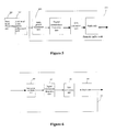
- Figure 4 is a schematic diagram illustrating a system according to an embodiment of the invention.
- Figure 5 is a schematic diagram illustrating a system according to another embodiment of the invention.
- Figure 6 is a schematic diagram illustrating another embodiment of the invention.
- transmission powers of different remote radio units are controlled by static power adjustment units inserted at the side of the remote radio units, instead of the conventional method of adjusting baseband output power by using static power level of cell level.
- An embodiment of the invention provides a method for power control.
- a static power adjustment unit is arranged at the side of remote radio unit, for example, the static power adjustment unit can be integrated in the remote radio unit, or can be arranged independently of the remote radio unit. The method will be discussed in detail as follows:
- a baseband processing unit processes a baseband signal and output the baseband signal to the remote radio units in a cell;
- the static power adjustment unit of the remote radio unit adjusts transmission power of the remote radio unit according to a static power level of the remote radio unit.
- the static power adjustment units of the remote radio units adjust the power of the baseband signal according to the static power levels of the remote radio units, before the remote radio units perform intermediate-frequency processing to the adjusted baseband signals and transmit the signals.
- the transmission powers of the remote radio units are adjusted.
- the static power level of each remote radio unit is the difference between transmission power required by the remote radio unit and power capability of the remote radio unit.
- the power capabilities of the remote radio units are not limited to be the same.
- Each remote radio unit can transmit signals according to its practical requirement through the adjustment performed by the static power adjustment unit of the remote radio unit.
- a cell level static power adjustment may be performed at the baseband processing unit.
- the method will be described as follows:
- Step 301 a baseband processing unit processes a baseband signal and output the baseband signal to the remote radio units in a cell.
- Step 302 a static power adjustment unit at the baseband processing unit adjusts the power of the baseband signal according to a static power level of the cell.
- the static power level of the cell may be the difference between the maximum transmission power required by the cell and the power capability of a remote radio unit with the highest capability.
- the power difference un-adjusted at the baseband processing unit may be adjusted on the remote radio units.
- Step 303 the static power adjustment unit of each remote radio unit adjusts the power of the received baseband signal according to static power level of the remote radio unit. Because a static power adjustment has been performed at the baseband processing unit in the last step, the static power level of each remote radio unit is the difference between the power of baseband signal resulted from the adjustment of step 302 and the power capability of the remote radio unit. Thus, the static power adjustment of common part of the remote radio units is implemented at the baseband processing unit, and the static power adjustment of differential parts of the remote radio units is implemented at the remote radio units.
- the remote radio units may further perform an intermediate-frequency process to the baseband signal and then transmit the signal with the powers adjusted by the static power adjustment units.
- this should not be considered as a limit to the invention.
- an embodiment of the invention provides a system for power control.
- the system includes a baseband processing unit 401, a remote radio unit 402, and a static power adjustment unit 403.
- the baseband processing unit 401 may output baseband signal to a plurality of multiple remote radio units at the same time.
- the baseband processing unit is adapted to process a baseband signal, for example physical layer processes to a baseband signal, etc. and output the baseband signal to the remote radio unit(s).
- the remote radio unit is adapted to receive the baseband signal adjusted by the static power adjustment unit, and perform intermediate-frequency processing to the baseband signal and transmit the signal.
- the static power adjustment unit is adapted to receive the baseband signal output by the baseband processing unit, and adjust the power of the baseband signal according to the static power level of the remote radio unit, so as to adjust the transmission power of the remote radio unit.
- the static power adjustment unit is not limited to being integrated in an RRU (in this case, the number of the static power adjustment unit is equal to the number of the remote radio units).
- the static power adjustment unit may be a separate processing module independent of the RRUs (in this case, a plurality of remote radio units may share one static power adjustment unit).
- the integration manner of the static power adjustment unit should not be considered as a limit of the invention.
- Figure 4 shows a scenario when a static power adjustment unit is integrated in an RRU.
- Figure 5 shows another preferred embodiment of the invention.
- a cell level static power adjustment unit 502 may also be inserted at the side of a baseband processing unit 501.
- the cell level static power adjustment unit 502 is adapted to adjust the power of baseband signal to be output to each remote radio unit, so that a common control may be performed to the output power before the precise adjustment to be performed by each remote radio unit, in order to improve the precision of the adjustment to be performed by each remote radio unit.
- the static power adjustment unit at the side of the remote radio unit may be referred to as the first static power adjustment unit
- the static power adjustment unit at the side of the baseband processing unit may be referred to as the second static power adjustment unit.
- an embodiment of the invention provides a remote radio unit as shown in Figure 6.
- the remote radio unit 605 includes the following units.
- a digital intermediate-frequency unit 602 adapted for shaping, filtering and digitally up-converting a downlink spread spectrum signal.
- a digital/analog (D/A) conversion unit adapted for converting the digital signal output by the digital intermediate-frequency unit to an analog signal.
- a radio unit adapted for up-converting the analog signal to a transmission frequency band and for filtering the up-converted analog signal and amplifying the power of the up-converted analog signal.
- a static power adjustment unit adapted for adjusting the power of the baseband signal according to the static power level of the remote radio unit, and for transmitting the adjusted baseband signal to the digital intermediate-frequency unit, so as to adjust the transmission power of the remote radio unit.
- the static power level of the remote radio unit is the difference between the transmission power required by the remote radio unit and the power capability of the remote radio unit.
- the static power level of the remote radio unit may be the difference between the power of the adjusted baseband signal and the power capability of the remote radio unit.
- the words “include” or “comprise” herein are to be construed in a logic sense. That is, the static power adjustment unit is arranged at the side of the remote radio unit, and is not necessarily integrated in the remote radio unit. In other words, the static power adjustment unit may be arranged independently of the remote radio unit.
- a remote radio unit is connected to the baseband processing unit, to process the baseband signal output by the baseband processing unit.
- the remote radio unit may be connected to the baseband processing unit via fibers or cables, etc. The connection manner should not be considered as a limit to the invention.
Landscapes
- Engineering & Computer Science (AREA)
- Computer Networks & Wireless Communication (AREA)
- Signal Processing (AREA)
- Mobile Radio Communication Systems (AREA)
- Transmitters (AREA)
- Remote Monitoring And Control Of Power-Distribution Networks (AREA)
- Selective Calling Equipment (AREA)
Abstract
Description
- The application claims the priority of
Chinese patent application No. 200610061839.1 - The invention relates to radio power adjustment techniques, and in particular, to a system and method for adjusting power of a remote radio unit, as well as a remote radio unit.
- Cell coverage is an important concept in the field of wireless communications. The concepts related with cell coverage include the following.
- Sector is a spatial and physical area, and represents the geographical range covered by an antenna.
- Cell is a logic concept, and is divided in the view of capacity and service. In a cell, all the users share the radio resources (e.g., code resources, frequency resources, etc.) of the cell.
- In a common macro cell coverage system, a cell typically belongs to a certain sector from the view of geographical range. Different cells in a sector are differentiated by frequency. However, in a scenario with special coverage requirements, such as indoor coverage, village coverage along a highway, and the like, a plurality of sectors are required for coverage in order to improve the communication quality. The case that a plurality of sectors share one logic cell is referred to as sector split. Figure 1 shows a method of sector split, i.e., Baseband processing Unit (BBU) + Remote Radio Unit (RRU). In Figure 1, "" represents a remote radio unit, "
 " represents a baseband processing unit, "○" represents the range covered by a certain remote radio unit, and "_____" represents a connection between the baseband processing unit and a remote radio unit.
- The attenuation of a radio signal is associated with the transmission path of the radio signal. In the same propagation environment, the ranges covered by the remote radio units are different, the transmission powers required by the remote radio units are accordingly different. In other words, different remote radio units in a cell may require different transmission powers. Accordingly, the power control should be performed in different manners for the different remote radio units. In the prior art, the power of a remote radio unit in a cell is controlled using a parameter referred to as static power level. The static power level of cell level is computed by a formula as follows:

- The maximum transmission power required by a cell is determined by the environment of the cell. The power capability of each remote radio unit is fixed in the process of designing, and can not be changed arbitrarily. The types of power capability of the remote radio units are limited, and the differences among the power capabilities of the remote radio units are small. In fact, the power capabilities of the remote radio units are usually the same.
- Figure 2 shows an implementation according to the prior art: a static
power adjustment unit 202, adapted for adjusting baseband output power according to the static power level, is arranged on abaseband processing unit 201. In Figure 2, the broken line block represents aremote radio unit 203. Each remote radio unit receives the same baseband power obtained from the adjustment of the staticpower adjustment unit 202. Aremote radio unit 203 includes a digital intermediate-frequency unit adapted for shaping, filtering, and digitally up-converting a downlink spread spectrum signal, a digital/analog (D/A) conversion unit adapted for converting the digital signal to an analog signal, and a radio unit adapted for up-converting the analog signal to a transmission frequency band and for filtering the up-converted analog signal and amplifying the power of the up-converted analog signal, so that theremote radio unit 203 may transmit the signal according to received power. - Thus, when there are a plurality of remote radio units in a cell, the unified power adjustment at only the baseband processing unit can not meet the different requirements for transmission power of the remote radio units. For instance, if there are 10 remote radio units in a cell, each of the remote radio units has a power capacity of 200mW (23dBm)and the maximum transmission power required by the cell is 100mW (20dBm), it can be derived from the above formula that the static power level of the cell is -3dB. In this case, if 5 remote radio units are required to have an output power of 100mW, and the rest 5 remote radio units are required to have an output power of 30mW, these requirements can not be satisfied by using only the static power level of cell level in the prior art.
- In summary, in the prior art, baseband output power is adjusted at only the baseband processing unit. Accordingly, all the remote radio units have to transmit signals at a same power level, the transmission powers of the remote radio units can not be adjusted differently. This has a limitation on the practical networking applications.
- Embodiments of the invention provide a system and a method for power control of a remote radio unit, as well as a remote radio unit, so that different remote radio units can have different output powers in a sector split environment.
- According to one aspect of the invention, a system for power control is provided, which includes
a baseband processing unit for processing a baseband signal;
at least one remote radio unit coupleable to the baseband processing unit;
at least one first static power adjustment unit adapted for controlling output power of the baseband processing unit according to static power level of the at least one remote radio unit. - In the system for power control, the power of remote radio units may be adjusted by the static power adjustment unit arranged at the side of the remote radio units. In this way, output powers of different remote radio units can be adjusted differently.
- According to another aspect of the invention, a remote radio unit is provided, which includes:
- a digital intermediate-frequency unit;
- a digital/analog conversion unit;
- a radio unit;
- the remote radio unit further includes a static power adjustment unit, adapted for power control according to a static power level of the remote radio unit, and for transmitting the adjusted baseband signal to the digital intermediate-frequency unit.
- As can be seen, a remote radio unit may cooperate with a static power adjustment unit arranged at the side of the remote radio unit so as to adjust the output power of the remote radio unit. In this way, the output powers of different remote radio units can be adjusted differently.
- According to another aspect of the invention, a method for power control is provided, which includes:
- obtaining a static power level of a remote radio unit;
- controlling output power of a baseband processing unit according to the static power level of the remote radio unit.
- As can be seen, remote radio units can adjust power by using the static power levels of the remote radio units. In this way, output powers of different remote radio units can be adjusted differently without any additional hardware cost. In addition, because the power adjustment is implemented on the remote radio units by using digital processing techniques, a wider dynamic range and an improved adjustment precision, as well as a wider application scenario, may be achieved.
- Figure 1 is a schematic diagram illustrating sector split;
- Figure 2 is a schematic diagram illustrating a system in the prior art;
- Figure 3 is a flow chart illustrating a method according to an embodiment of the invention;
- Figure 4 is a schematic diagram illustrating a system according to an embodiment of the invention;
- Figure 5 is a schematic diagram illustrating a system according to another embodiment of the invention;
- Figure 6 is a schematic diagram illustrating another embodiment of the invention.
- In embodiments of the invention, transmission powers of different remote radio units are controlled by static power adjustment units inserted at the side of the remote radio units, instead of the conventional method of adjusting baseband output power by using static power level of cell level.
- The detailed description of the present invention will be given below with reference to embodiments and the drawings, to make the object, the technical solutions and advantages of the invention better understood.
- An embodiment of the invention provides a method for power control. A static power adjustment unit is arranged at the side of remote radio unit, for example, the static power adjustment unit can be integrated in the remote radio unit, or can be arranged independently of the remote radio unit. The method will be discussed in detail as follows:
- S1: a baseband processing unit processes a baseband signal and output the baseband signal to the remote radio units in a cell;
- S2: after each remote radio unit receives the baseband signal, the static power adjustment unit of the remote radio unit adjusts transmission power of the remote radio unit according to a static power level of the remote radio unit. In other words, the static power adjustment units of the remote radio units adjust the power of the baseband signal according to the static power levels of the remote radio units, before the remote radio units perform intermediate-frequency processing to the adjusted baseband signals and transmit the signals. Thus, the transmission powers of the remote radio units are adjusted.
- The static power level of each remote radio unit is the difference between transmission power required by the remote radio unit and power capability of the remote radio unit. In the embodiment of the invention, the power capabilities of the remote radio units are not limited to be the same. Each remote radio unit can transmit signals according to its practical requirement through the adjustment performed by the static power adjustment unit of the remote radio unit.
- Before the static power adjustment units adjust the powers of the remote radio units, a cell level static power adjustment may be performed at the baseband processing unit. With reference to Figure 3, the method will be described as follows:
- Step 301: a baseband processing unit processes a baseband signal and output the baseband signal to the remote radio units in a cell.
- Step 302: a static power adjustment unit at the baseband processing unit adjusts the power of the baseband signal according to a static power level of the cell.
- Taking into consideration the possible differences between the power capabilities of the remote radio units, the static power level of the cell may be the difference between the maximum transmission power required by the cell and the power capability of a remote radio unit with the highest capability. The power difference un-adjusted at the baseband processing unit may be adjusted on the remote radio units.
- Step 303: the static power adjustment unit of each remote radio unit adjusts the power of the received baseband signal according to static power level of the remote radio unit. Because a static power adjustment has been performed at the baseband processing unit in the last step, the static power level of each remote radio unit is the difference between the power of baseband signal resulted from the adjustment of
step 302 and the power capability of the remote radio unit. Thus, the static power adjustment of common part of the remote radio units is implemented at the baseband processing unit, and the static power adjustment of differential parts of the remote radio units is implemented at the remote radio units. - In the implementation processes according to embodiments of the invention, after the adjustment performed by the static power adjustment units of the remote radio units, the remote radio units may further perform an intermediate-frequency process to the baseband signal and then transmit the signal with the powers adjusted by the static power adjustment units. However, this should not be considered as a limit to the invention.
- In addition, an embodiment of the invention provides a system for power control. As shown in Figure 4, the system includes a
baseband processing unit 401, aremote radio unit 402, and a staticpower adjustment unit 403. In this embodiment, for simplicity, only oneremote radio unit 402 is shown, it should be noted that thebaseband processing unit 401 may output baseband signal to a plurality of multiple remote radio units at the same time. - The baseband processing unit is adapted to process a baseband signal, for example physical layer processes to a baseband signal, etc. and output the baseband signal to the remote radio unit(s).
- The remote radio unit is adapted to receive the baseband signal adjusted by the static power adjustment unit, and perform intermediate-frequency processing to the baseband signal and transmit the signal.
- The static power adjustment unit is adapted to receive the baseband signal output by the baseband processing unit, and adjust the power of the baseband signal according to the static power level of the remote radio unit, so as to adjust the transmission power of the remote radio unit.
- It should be noted that, in the system according to the embodiment of the invention, the static power adjustment unit is not limited to being integrated in an RRU (in this case, the number of the static power adjustment unit is equal to the number of the remote radio units). Alternatively, the static power adjustment unit may be a separate processing module independent of the RRUs (in this case, a plurality of remote radio units may share one static power adjustment unit). The integration manner of the static power adjustment unit should not be considered as a limit of the invention. Figure 4 shows a scenario when a static power adjustment unit is integrated in an RRU.
- Figure 5 shows another preferred embodiment of the invention. In addition to a static
power adjustment unit 503 integrated at the side of aremote radio unit 504, a cell level staticpower adjustment unit 502 may also be inserted at the side of abaseband processing unit 501. The cell level staticpower adjustment unit 502 is adapted to adjust the power of baseband signal to be output to each remote radio unit, so that a common control may be performed to the output power before the precise adjustment to be performed by each remote radio unit, in order to improve the precision of the adjustment to be performed by each remote radio unit. - It should be appreciated that, the static power adjustment unit at the side of the remote radio unit may be referred to as the first static power adjustment unit, and the static power adjustment unit at the side of the baseband processing unit may be referred to as the second static power adjustment unit.
- In addition, an embodiment of the invention provides a remote radio unit as shown in Figure 6.
- In particular, the
remote radio unit 605 includes the following units. - A digital intermediate-
frequency unit 602, adapted for shaping, filtering and digitally up-converting a downlink spread spectrum signal. - A digital/analog (D/A) conversion unit, adapted for converting the digital signal output by the digital intermediate-frequency unit to an analog signal.
- A radio unit, adapted for up-converting the analog signal to a transmission frequency band and for filtering the up-converted analog signal and amplifying the power of the up-converted analog signal.
- A static power adjustment unit, adapted for adjusting the power of the baseband signal according to the static power level of the remote radio unit, and for transmitting the adjusted baseband signal to the digital intermediate-frequency unit, so as to adjust the transmission power of the remote radio unit. The static power level of the remote radio unit is the difference between the transmission power required by the remote radio unit and the power capability of the remote radio unit. Alternatively, the static power level of the remote radio unit may be the difference between the power of the adjusted baseband signal and the power capability of the remote radio unit.
- It shall be noted that the words "include" or "comprise" herein are to be construed in a logic sense. That is, the static power adjustment unit is arranged at the side of the remote radio unit, and is not necessarily integrated in the remote radio unit. In other words, the static power adjustment unit may be arranged independently of the remote radio unit.
- In an embodiment, a remote radio unit is connected to the baseband processing unit, to process the baseband signal output by the baseband processing unit. The remote radio unit may be connected to the baseband processing unit via fibers or cables, etc. The connection manner should not be considered as a limit to the invention.
- The above described embodiments are illustrative, and the invention shall not be limited thereto. Various modifications and variations made thereto without departing from the spirit and principle of the invention are intended to be covered within the scope of the invention as defined by the accompanying claims.
Claims (12)
- A system for power control, comprising:a baseband processing unit for processing a baseband signal;at least one remote radio unit coupleable to the baseband processing unit; characterized in that the system further comprisesat least one first static power adjustment unit adapted for controlling output power of the baseband processing unit according to static power level of the at least one remote radio unit.
- The system according to claim 1, characterized in that, the first static power adjustment unit is integrated in the at least one remote radio unit or arranged independent of the at least one remote radio unit.
- The system according to claim 1 or 2, characterized in that, a second static power adjustment unit is further included at side of the baseband processing unit, the second static power adjustment unit being adapted to adjust power of the baseband signal to be output according to static power level of a cell.
- The system according to claim 3, characterized in that, the static power level of the remote radio unit is a difference between transmission power required by the remote radio unit and power capability of the remote radio unit; or
a difference between output power adjusted by the second static power adjustment unit and power capability of the remote radio unit. - The system according to any one of claims 1-4, characterized in that, the remote radio unit is connected to the baseband processing unit via optical fiber or cable.
- A remote radio unit, comprising:a digital intermediate-frequency unit;a digital/analog conversion unit;a radio unit,;characterized in that, the remote radio unit further comprises a static power adjustment unit, adapted for power control according to static power level of the remote radio unit.
- The remote radio unit according to claim 6, characterized in that,
the static power level of the remote radio unit is a difference between transmission power required by the remote radio unit and power capability of the remote radio unit; or
a difference between output power of a baseband unit and power capability of the remote radio unit. - A method for power control, comprising:obtaining a static power level of a remote radio unit;controlling output power of a baseband processing unit according to the static power level of the remote radio unit.
- The method according to claim 8, characterized in that, the static power level of the remote radio unit is a difference between transmission power required by the remote radio unit and power capability of the remote radio unit.
- The method according to claim 8 or 9, characterized in that before controlling output power of a baseband processing unit according to the static power level of the remote radio unit, further comprising: controlling the output power according to static power level of a cell.
- The method according to claim 10, characterized in that, the static power level of the remote radio unit is a difference between power adjusted based on the static power level of a cell and power capability of the remote radio unit.
- The method according to claim 10, characterized in that, the static power level of the cell is a difference between maximum transmission power required by the cell and power capability of a remote radio unit with a highest power capability.
Applications Claiming Priority (1)
| Application Number | Priority Date | Filing Date | Title |
|---|---|---|---|
| CNA2006100618391A CN1901393A (en) | 2006-07-26 | 2006-07-26 | System and method for regulating far end radio frequency unit power and far end radio frequency unit |
Publications (2)
| Publication Number | Publication Date |
|---|---|
| EP1883167A1 true EP1883167A1 (en) | 2008-01-30 |
| EP1883167B1 EP1883167B1 (en) | 2011-03-09 |
Family
ID=37657162
Family Applications (1)
| Application Number | Title | Priority Date | Filing Date |
|---|---|---|---|
| EP07113181A Not-in-force EP1883167B1 (en) | 2006-07-26 | 2007-07-26 | A system and method for power control, and a remote radio unit |
Country Status (7)
| Country | Link |
|---|---|
| EP (1) | EP1883167B1 (en) |
| JP (1) | JP4713549B2 (en) |
| CN (2) | CN1901393A (en) |
| AT (1) | ATE501617T1 (en) |
| DE (1) | DE602007012965D1 (en) |
| PT (1) | PT1883167E (en) |
| WO (1) | WO2008014700A1 (en) |
Cited By (5)
| Publication number | Priority date | Publication date | Assignee | Title |
|---|---|---|---|---|
| CN101835185B (en) * | 2009-03-11 | 2013-03-20 | 中兴通讯股份有限公司 | Method for carrying out control or equipment information inquiry on base station equipment |
| CN103297986A (en) * | 2013-06-09 | 2013-09-11 | 北京邮电大学 | Networking method for intelligent adaption wireless communication networks |
| CN103401929A (en) * | 2013-08-05 | 2013-11-20 | 北京邮电大学 | Self-adaptive networking method based on baseband with large-scale processing ability and business |
| US11563492B2 (en) | 2013-12-23 | 2023-01-24 | Dali Wireless, Inc. | Virtual radio access network using software-defined network of remotes and digital multiplexing switches |
| US11564110B2 (en) | 2011-11-07 | 2023-01-24 | Dali Wireless, Inc. | Soft hand-off and routing data in a virtualized distributed antenna system |
Families Citing this family (13)
| Publication number | Priority date | Publication date | Assignee | Title |
|---|---|---|---|---|
| CN101232653B (en) * | 2007-01-22 | 2012-07-18 | 中兴通讯股份有限公司 | Radio frequency zoom out system based on number intermediate frequency transmission |
| CN101102606B (en) * | 2007-07-20 | 2010-07-14 | 中兴通讯股份有限公司 | An Indoor Distributed System and Implementation Method Supporting Real-time Network Optimization |
| CN101394658B (en) * | 2007-09-21 | 2013-12-18 | 中兴通讯股份有限公司 | Apparatus realizing distributed wireless cell and communication method |
| CN101146257B (en) * | 2007-10-16 | 2011-08-31 | 深圳国人通信有限公司 | Method and system for improving synchronization precision of data transmission |
| CN101567712B (en) * | 2008-04-23 | 2012-12-19 | 中兴通讯股份有限公司 | Subdistrict division power configuration method and system |
| CN102055502A (en) * | 2009-11-02 | 2011-05-11 | 中兴通讯股份有限公司 | Method and device for automatic scaling |
| CN102316558A (en) * | 2010-06-30 | 2012-01-11 | 中兴通讯股份有限公司 | Method and device for realizing wireless base station power supply management and control |
| CN102457882B (en) * | 2010-10-22 | 2015-05-13 | 中兴通讯股份有限公司 | Method and device for detecting radio frequency channel in worldwide interoperability system for microwave access |
| CN102843692A (en) * | 2011-06-22 | 2012-12-26 | 中兴通讯股份有限公司 | Method and device for sharing multi-carrier power of same RRU by operators |
| CN103686973B (en) * | 2013-12-30 | 2017-05-17 | 大唐移动通信设备有限公司 | Power adjustment method and device of remote radio unit |
| CN103781168B (en) * | 2014-02-18 | 2017-01-18 | 中国科学院声学研究所 | Power distribution method and system of cellular network |
| CN107801238B (en) * | 2016-09-05 | 2022-08-02 | 中兴通讯股份有限公司 | Method and device for inter-cell power cooperation in LTE scene |
| CN108347276B (en) * | 2018-02-08 | 2021-04-13 | Oppo广东移动通信有限公司 | Method, device, storage medium and electronic device for dynamically adjusting radio frequency path |
Citations (2)
| Publication number | Priority date | Publication date | Assignee | Title |
|---|---|---|---|---|
| WO2003075484A1 (en) * | 2002-03-07 | 2003-09-12 | Nokia Corporation | Power control device and method for controlling the transmission power of a transmitter in a mobile communication network |
| EP1361674A1 (en) * | 2002-05-08 | 2003-11-12 | Motorola, Inc. | Method and apparatus for controlling power associated with a transmitting unit |
Family Cites Families (7)
| Publication number | Priority date | Publication date | Assignee | Title |
|---|---|---|---|---|
| CN1163097C (en) * | 2001-05-25 | 2004-08-18 | 华为技术有限公司 | Open-loop power control device and method for broadband multi-carrier base station |
| US7151740B2 (en) * | 2001-02-28 | 2006-12-19 | Cingular Wireless Ii, Llc | Transmit power control for an OFDM-based wireless communication system |
| US6978151B2 (en) * | 2001-05-10 | 2005-12-20 | Koninklijke Philips Electronics N.V. | Updating path loss estimation for power control and link adaptation in IEEE 802.11h WLAN |
| JP2003299143A (en) * | 2002-04-03 | 2003-10-17 | Toshiba Corp | Mobile communication system |
| JP2004207840A (en) * | 2002-12-24 | 2004-07-22 | Nec Corp | Method of managing radio resource, managing apparatus used therefor, base station and terminal |
| US7885651B2 (en) * | 2004-06-18 | 2011-02-08 | Mitsubishi Electric Corporation | Autonomous cell shaping method |
| JP2006180266A (en) * | 2004-12-22 | 2006-07-06 | Sanyo Electric Co Ltd | Radio base station, transmission power control method, and transmission power control program |
-
2006
- 2006-07-26 CN CNA2006100618391A patent/CN1901393A/en active Pending
-
2007
- 2007-07-06 CN CN200780000173.1A patent/CN101548477B/en not_active Expired - Fee Related
- 2007-07-06 WO PCT/CN2007/070247 patent/WO2008014700A1/en not_active Ceased
- 2007-07-25 JP JP2007193378A patent/JP4713549B2/en active Active
- 2007-07-26 EP EP07113181A patent/EP1883167B1/en not_active Not-in-force
- 2007-07-26 PT PT07113181T patent/PT1883167E/en unknown
- 2007-07-26 DE DE602007012965T patent/DE602007012965D1/en active Active
- 2007-07-26 AT AT07113181T patent/ATE501617T1/en active
Patent Citations (2)
| Publication number | Priority date | Publication date | Assignee | Title |
|---|---|---|---|---|
| WO2003075484A1 (en) * | 2002-03-07 | 2003-09-12 | Nokia Corporation | Power control device and method for controlling the transmission power of a transmitter in a mobile communication network |
| EP1361674A1 (en) * | 2002-05-08 | 2003-11-12 | Motorola, Inc. | Method and apparatus for controlling power associated with a transmitting unit |
Cited By (7)
| Publication number | Priority date | Publication date | Assignee | Title |
|---|---|---|---|---|
| CN101835185B (en) * | 2009-03-11 | 2013-03-20 | 中兴通讯股份有限公司 | Method for carrying out control or equipment information inquiry on base station equipment |
| US11564110B2 (en) | 2011-11-07 | 2023-01-24 | Dali Wireless, Inc. | Soft hand-off and routing data in a virtualized distributed antenna system |
| CN103297986A (en) * | 2013-06-09 | 2013-09-11 | 北京邮电大学 | Networking method for intelligent adaption wireless communication networks |
| CN103297986B (en) * | 2013-06-09 | 2015-07-22 | 北京邮电大学 | Networking method for intelligent adaption wireless communication networks |
| CN103401929A (en) * | 2013-08-05 | 2013-11-20 | 北京邮电大学 | Self-adaptive networking method based on baseband with large-scale processing ability and business |
| CN103401929B (en) * | 2013-08-05 | 2016-08-10 | 北京邮电大学 | Based on massive processing power base band and the network-building method of service adaptation |
| US11563492B2 (en) | 2013-12-23 | 2023-01-24 | Dali Wireless, Inc. | Virtual radio access network using software-defined network of remotes and digital multiplexing switches |
Also Published As
| Publication number | Publication date |
|---|---|
| PT1883167E (en) | 2011-05-25 |
| DE602007012965D1 (en) | 2011-04-21 |
| EP1883167B1 (en) | 2011-03-09 |
| CN1901393A (en) | 2007-01-24 |
| JP4713549B2 (en) | 2011-06-29 |
| CN101548477B (en) | 2013-08-07 |
| WO2008014700A1 (en) | 2008-02-07 |
| JP2008035521A (en) | 2008-02-14 |
| ATE501617T1 (en) | 2011-03-15 |
| CN101548477A (en) | 2009-09-30 |
Similar Documents
| Publication | Publication Date | Title |
|---|---|---|
| EP1883167B1 (en) | A system and method for power control, and a remote radio unit | |
| US20220337705A1 (en) | Tdd time slot splitting | |
| EP1570546B1 (en) | Adaptive passive distributed antenna system | |
| EP4017144A1 (en) | Information transmission method and device, information reception method and device, communication node, and storage medium | |
| US10506527B2 (en) | Mechanism for enhancing power control in time division based communications | |
| EP3055980B1 (en) | Systems and methods for noise floor optimization in distributed antenna system with direct digital interface to base station | |
| US11310751B2 (en) | Maximum permissible exposure assisted uplink traffic grant allocation | |
| WO2022205373A1 (en) | Uplink power control method and user equipment | |
| CN113615280B (en) | Power control method and related device | |
| CN102740436B (en) | Power adjusting method and base station | |
| EP1936829A1 (en) | Suppression of interferences between cells | |
| EP4014597B1 (en) | Panel specific ul power control | |
| KR20110091502A (en) | Uplink transmission power control method, system and base station | |
| EP3804252B1 (en) | Device for hybrid transmitter | |
| EP2553985B1 (en) | Communication control method, communication system, and management server | |
| EP4164315B1 (en) | Power acquisition method and apparatus, and node device | |
| US20260046782A1 (en) | Uplink power control method, device, and storage medium | |
| CN115085788B (en) | Method and system for adjusting uplink gain of repeater | |
| KR101145204B1 (en) | Transmitting power control device and method of sector antenna system | |
| US11425788B2 (en) | Distributed capacity base station architecture for broadband access with enhanced in-band GPS co-existence | |
| EP2848052B1 (en) | Method for indication of reference symbol transmission power change in cellular network | |
| EP2428077B1 (en) | A method for controlling the power for broadcasting a cognitive pilot channel | |
| KR102238582B1 (en) | Method and Apparatus for Balancing Uplink Gain | |
| CN120166441A (en) | A communication method and related device | |
| US20130242877A1 (en) | Method and apparatus for notifying a node in a multi-node system |
Legal Events
| Date | Code | Title | Description |
|---|---|---|---|
| PUAI | Public reference made under article 153(3) epc to a published international application that has entered the european phase |
Free format text: ORIGINAL CODE: 0009012 |
|
| 17P | Request for examination filed |
Effective date: 20070726 |
|
| AK | Designated contracting states |
Kind code of ref document: A1 Designated state(s): AT BE BG CH CY CZ DE DK EE ES FI FR GB GR HU IE IS IT LI LT LU LV MC MT NL PL PT RO SE SI SK TR |
|
| AX | Request for extension of the european patent |
Extension state: AL BA HR MK YU |
|
| 17Q | First examination report despatched |
Effective date: 20080417 |
|
| AKX | Designation fees paid |
Designated state(s): AT BE BG CH CY CZ DE DK EE ES FI FR GB GR HU IE IS IT LI LT LU LV MC MT NL PL PT RO SE SI SK TR |
|
| GRAP | Despatch of communication of intention to grant a patent |
Free format text: ORIGINAL CODE: EPIDOSNIGR1 |
|
| RIC1 | Information provided on ipc code assigned before grant |
Ipc: H04W 52/04 20090101AFI20100831BHEP |
|
| GRAS | Grant fee paid |
Free format text: ORIGINAL CODE: EPIDOSNIGR3 |
|
| GRAA | (expected) grant |
Free format text: ORIGINAL CODE: 0009210 |
|
| AK | Designated contracting states |
Kind code of ref document: B1 Designated state(s): AT BE BG CH CY CZ DE DK EE ES FI FR GB GR HU IE IS IT LI LT LU LV MC MT NL PL PT RO SE SI SK TR |
|
| REG | Reference to a national code |
Ref country code: GB Ref legal event code: FG4D |
|
| REG | Reference to a national code |
Ref country code: CH Ref legal event code: EP |
|
| REG | Reference to a national code |
Ref country code: IE Ref legal event code: FG4D |
|
| REF | Corresponds to: |
Ref document number: 602007012965 Country of ref document: DE Date of ref document: 20110421 Kind code of ref document: P |
|
| REG | Reference to a national code |
Ref country code: DE Ref legal event code: R096 Ref document number: 602007012965 Country of ref document: DE Effective date: 20110421 |
|
| REG | Reference to a national code |
Ref country code: PT Ref legal event code: SC4A Free format text: AVAILABILITY OF NATIONAL TRANSLATION Effective date: 20110516 |
|
| REG | Reference to a national code |
Ref country code: NL Ref legal event code: VDEP Effective date: 20110309 |
|
| PG25 | Lapsed in a contracting state [announced via postgrant information from national office to epo] |
Ref country code: LV Free format text: LAPSE BECAUSE OF FAILURE TO SUBMIT A TRANSLATION OF THE DESCRIPTION OR TO PAY THE FEE WITHIN THE PRESCRIBED TIME-LIMIT Effective date: 20110309 Ref country code: ES Free format text: LAPSE BECAUSE OF FAILURE TO SUBMIT A TRANSLATION OF THE DESCRIPTION OR TO PAY THE FEE WITHIN THE PRESCRIBED TIME-LIMIT Effective date: 20110620 Ref country code: GR Free format text: LAPSE BECAUSE OF FAILURE TO SUBMIT A TRANSLATION OF THE DESCRIPTION OR TO PAY THE FEE WITHIN THE PRESCRIBED TIME-LIMIT Effective date: 20110610 Ref country code: SE Free format text: LAPSE BECAUSE OF FAILURE TO SUBMIT A TRANSLATION OF THE DESCRIPTION OR TO PAY THE FEE WITHIN THE PRESCRIBED TIME-LIMIT Effective date: 20110309 Ref country code: LT Free format text: LAPSE BECAUSE OF FAILURE TO SUBMIT A TRANSLATION OF THE DESCRIPTION OR TO PAY THE FEE WITHIN THE PRESCRIBED TIME-LIMIT Effective date: 20110309 |
|
| LTIE | Lt: invalidation of european patent or patent extension |
Effective date: 20110309 |
|
| PG25 | Lapsed in a contracting state [announced via postgrant information from national office to epo] |
Ref country code: CY Free format text: LAPSE BECAUSE OF FAILURE TO SUBMIT A TRANSLATION OF THE DESCRIPTION OR TO PAY THE FEE WITHIN THE PRESCRIBED TIME-LIMIT Effective date: 20110309 Ref country code: BG Free format text: LAPSE BECAUSE OF FAILURE TO SUBMIT A TRANSLATION OF THE DESCRIPTION OR TO PAY THE FEE WITHIN THE PRESCRIBED TIME-LIMIT Effective date: 20110609 Ref country code: FI Free format text: LAPSE BECAUSE OF FAILURE TO SUBMIT A TRANSLATION OF THE DESCRIPTION OR TO PAY THE FEE WITHIN THE PRESCRIBED TIME-LIMIT Effective date: 20110309 Ref country code: SI Free format text: LAPSE BECAUSE OF FAILURE TO SUBMIT A TRANSLATION OF THE DESCRIPTION OR TO PAY THE FEE WITHIN THE PRESCRIBED TIME-LIMIT Effective date: 20110309 Ref country code: NL Free format text: LAPSE BECAUSE OF FAILURE TO SUBMIT A TRANSLATION OF THE DESCRIPTION OR TO PAY THE FEE WITHIN THE PRESCRIBED TIME-LIMIT Effective date: 20110309 |
|
| PG25 | Lapsed in a contracting state [announced via postgrant information from national office to epo] |
Ref country code: BE Free format text: LAPSE BECAUSE OF FAILURE TO SUBMIT A TRANSLATION OF THE DESCRIPTION OR TO PAY THE FEE WITHIN THE PRESCRIBED TIME-LIMIT Effective date: 20110309 |
|
| PG25 | Lapsed in a contracting state [announced via postgrant information from national office to epo] |
Ref country code: EE Free format text: LAPSE BECAUSE OF FAILURE TO SUBMIT A TRANSLATION OF THE DESCRIPTION OR TO PAY THE FEE WITHIN THE PRESCRIBED TIME-LIMIT Effective date: 20110309 |
|
| PG25 | Lapsed in a contracting state [announced via postgrant information from national office to epo] |
Ref country code: RO Free format text: LAPSE BECAUSE OF FAILURE TO SUBMIT A TRANSLATION OF THE DESCRIPTION OR TO PAY THE FEE WITHIN THE PRESCRIBED TIME-LIMIT Effective date: 20110309 Ref country code: CZ Free format text: LAPSE BECAUSE OF FAILURE TO SUBMIT A TRANSLATION OF THE DESCRIPTION OR TO PAY THE FEE WITHIN THE PRESCRIBED TIME-LIMIT Effective date: 20110309 Ref country code: IS Free format text: LAPSE BECAUSE OF FAILURE TO SUBMIT A TRANSLATION OF THE DESCRIPTION OR TO PAY THE FEE WITHIN THE PRESCRIBED TIME-LIMIT Effective date: 20110709 Ref country code: SK Free format text: LAPSE BECAUSE OF FAILURE TO SUBMIT A TRANSLATION OF THE DESCRIPTION OR TO PAY THE FEE WITHIN THE PRESCRIBED TIME-LIMIT Effective date: 20110309 |
|
| PG25 | Lapsed in a contracting state [announced via postgrant information from national office to epo] |
Ref country code: MT Free format text: LAPSE BECAUSE OF FAILURE TO SUBMIT A TRANSLATION OF THE DESCRIPTION OR TO PAY THE FEE WITHIN THE PRESCRIBED TIME-LIMIT Effective date: 20110309 |
|
| PLBE | No opposition filed within time limit |
Free format text: ORIGINAL CODE: 0009261 |
|
| STAA | Information on the status of an ep patent application or granted ep patent |
Free format text: STATUS: NO OPPOSITION FILED WITHIN TIME LIMIT |
|
| 26N | No opposition filed |
Effective date: 20111212 |
|
| PG25 | Lapsed in a contracting state [announced via postgrant information from national office to epo] |
Ref country code: DK Free format text: LAPSE BECAUSE OF FAILURE TO SUBMIT A TRANSLATION OF THE DESCRIPTION OR TO PAY THE FEE WITHIN THE PRESCRIBED TIME-LIMIT Effective date: 20110309 Ref country code: PL Free format text: LAPSE BECAUSE OF FAILURE TO SUBMIT A TRANSLATION OF THE DESCRIPTION OR TO PAY THE FEE WITHIN THE PRESCRIBED TIME-LIMIT Effective date: 20110309 Ref country code: MC Free format text: LAPSE BECAUSE OF NON-PAYMENT OF DUE FEES Effective date: 20110731 |
|
| REG | Reference to a national code |
Ref country code: CH Ref legal event code: PL |
|
| REG | Reference to a national code |
Ref country code: DE Ref legal event code: R097 Ref document number: 602007012965 Country of ref document: DE Effective date: 20111212 |
|
| REG | Reference to a national code |
Ref country code: IE Ref legal event code: MM4A |
|
| PG25 | Lapsed in a contracting state [announced via postgrant information from national office to epo] |
Ref country code: CH Free format text: LAPSE BECAUSE OF NON-PAYMENT OF DUE FEES Effective date: 20110731 Ref country code: LI Free format text: LAPSE BECAUSE OF NON-PAYMENT OF DUE FEES Effective date: 20110731 |
|
| PG25 | Lapsed in a contracting state [announced via postgrant information from national office to epo] |
Ref country code: IE Free format text: LAPSE BECAUSE OF NON-PAYMENT OF DUE FEES Effective date: 20110726 |
|
| PG25 | Lapsed in a contracting state [announced via postgrant information from national office to epo] |
Ref country code: LU Free format text: LAPSE BECAUSE OF NON-PAYMENT OF DUE FEES Effective date: 20110726 |
|
| PG25 | Lapsed in a contracting state [announced via postgrant information from national office to epo] |
Ref country code: TR Free format text: LAPSE BECAUSE OF FAILURE TO SUBMIT A TRANSLATION OF THE DESCRIPTION OR TO PAY THE FEE WITHIN THE PRESCRIBED TIME-LIMIT Effective date: 20110309 |
|
| PG25 | Lapsed in a contracting state [announced via postgrant information from national office to epo] |
Ref country code: HU Free format text: LAPSE BECAUSE OF FAILURE TO SUBMIT A TRANSLATION OF THE DESCRIPTION OR TO PAY THE FEE WITHIN THE PRESCRIBED TIME-LIMIT Effective date: 20110309 |
|
| REG | Reference to a national code |
Ref country code: FR Ref legal event code: PLFP Year of fee payment: 10 |
|
| REG | Reference to a national code |
Ref country code: FR Ref legal event code: PLFP Year of fee payment: 11 |
|
| REG | Reference to a national code |
Ref country code: FR Ref legal event code: PLFP Year of fee payment: 12 |
|
| P01 | Opt-out of the competence of the unified patent court (upc) registered |
Effective date: 20230524 |
|
| PGFP | Annual fee paid to national office [announced via postgrant information from national office to epo] |
Ref country code: IT Payment date: 20230612 Year of fee payment: 17 Ref country code: FR Payment date: 20230620 Year of fee payment: 17 |
|
| PGFP | Annual fee paid to national office [announced via postgrant information from national office to epo] |
Ref country code: GB Payment date: 20230601 Year of fee payment: 17 Ref country code: AT Payment date: 20230626 Year of fee payment: 17 |
|
| PGFP | Annual fee paid to national office [announced via postgrant information from national office to epo] |
Ref country code: PT Payment date: 20230724 Year of fee payment: 17 Ref country code: DE Payment date: 20230531 Year of fee payment: 17 |
|
| REG | Reference to a national code |
Ref country code: DE Ref legal event code: R119 Ref document number: 602007012965 Country of ref document: DE |
|
| REG | Reference to a national code |
Ref country code: AT Ref legal event code: MM01 Ref document number: 501617 Country of ref document: AT Kind code of ref document: T Effective date: 20240726 |
|
| GBPC | Gb: european patent ceased through non-payment of renewal fee |
Effective date: 20240726 |
|
| PG25 | Lapsed in a contracting state [announced via postgrant information from national office to epo] |
Ref country code: DE Free format text: LAPSE BECAUSE OF NON-PAYMENT OF DUE FEES Effective date: 20250201 Ref country code: PT Free format text: LAPSE BECAUSE OF NON-PAYMENT OF DUE FEES Effective date: 20250127 |
|
| PG25 | Lapsed in a contracting state [announced via postgrant information from national office to epo] |
Ref country code: AT Free format text: LAPSE BECAUSE OF NON-PAYMENT OF DUE FEES Effective date: 20240726 |
|
| PG25 | Lapsed in a contracting state [announced via postgrant information from national office to epo] |
Ref country code: FR Free format text: LAPSE BECAUSE OF NON-PAYMENT OF DUE FEES Effective date: 20240731 |
|
| PG25 | Lapsed in a contracting state [announced via postgrant information from national office to epo] |
Ref country code: GB Free format text: LAPSE BECAUSE OF NON-PAYMENT OF DUE FEES Effective date: 20240726 |
|
| PG25 | Lapsed in a contracting state [announced via postgrant information from national office to epo] |
Ref country code: IT Free format text: LAPSE BECAUSE OF NON-PAYMENT OF DUE FEES Effective date: 20240726 |