EP1882822A2 - Cooled exhaust liner assembly for a gas turbine - Google Patents
Cooled exhaust liner assembly for a gas turbine Download PDFInfo
- Publication number
- EP1882822A2 EP1882822A2 EP07252042A EP07252042A EP1882822A2 EP 1882822 A2 EP1882822 A2 EP 1882822A2 EP 07252042 A EP07252042 A EP 07252042A EP 07252042 A EP07252042 A EP 07252042A EP 1882822 A2 EP1882822 A2 EP 1882822A2
- Authority
- EP
- European Patent Office
- Prior art keywords
- assembly
- interface
- recited
- liner
- seal land
- Prior art date
- Legal status (The legal status is an assumption and is not a legal conclusion. Google has not performed a legal analysis and makes no representation as to the accuracy of the status listed.)
- Granted
Links
Images


Classifications
-
- F—MECHANICAL ENGINEERING; LIGHTING; HEATING; WEAPONS; BLASTING
- F01—MACHINES OR ENGINES IN GENERAL; ENGINE PLANTS IN GENERAL; STEAM ENGINES
- F01D—NON-POSITIVE DISPLACEMENT MACHINES OR ENGINES, e.g. STEAM TURBINES
- F01D25/00—Component parts, details, or accessories, not provided for in, or of interest apart from, other groups
- F01D25/30—Exhaust heads, chambers, or the like
-
- F—MECHANICAL ENGINEERING; LIGHTING; HEATING; WEAPONS; BLASTING
- F01—MACHINES OR ENGINES IN GENERAL; ENGINE PLANTS IN GENERAL; STEAM ENGINES
- F01D—NON-POSITIVE DISPLACEMENT MACHINES OR ENGINES, e.g. STEAM TURBINES
- F01D11/00—Preventing or minimising internal leakage of working-fluid, e.g. between stages
- F01D11/005—Sealing means between non relatively rotating elements
-
- F—MECHANICAL ENGINEERING; LIGHTING; HEATING; WEAPONS; BLASTING
- F01—MACHINES OR ENGINES IN GENERAL; ENGINE PLANTS IN GENERAL; STEAM ENGINES
- F01D—NON-POSITIVE DISPLACEMENT MACHINES OR ENGINES, e.g. STEAM TURBINES
- F01D25/00—Component parts, details, or accessories, not provided for in, or of interest apart from, other groups
- F01D25/08—Cooling; Heating; Heat-insulation
- F01D25/12—Cooling
-
- F—MECHANICAL ENGINEERING; LIGHTING; HEATING; WEAPONS; BLASTING
- F02—COMBUSTION ENGINES; HOT-GAS OR COMBUSTION-PRODUCT ENGINE PLANTS
- F02K—JET-PROPULSION PLANTS
- F02K1/00—Plants characterised by the form or arrangement of the jet pipe or nozzle; Jet pipes or nozzles peculiar thereto
- F02K1/78—Other construction of jet pipes
- F02K1/82—Jet pipe walls, e.g. liners
- F02K1/822—Heat insulating structures or liners, cooling arrangements, e.g. post combustion liners; Infrared radiation suppressors
-
- Y—GENERAL TAGGING OF NEW TECHNOLOGICAL DEVELOPMENTS; GENERAL TAGGING OF CROSS-SECTIONAL TECHNOLOGIES SPANNING OVER SEVERAL SECTIONS OF THE IPC; TECHNICAL SUBJECTS COVERED BY FORMER USPC CROSS-REFERENCE ART COLLECTIONS [XRACs] AND DIGESTS
- Y02—TECHNOLOGIES OR APPLICATIONS FOR MITIGATION OR ADAPTATION AGAINST CLIMATE CHANGE
- Y02T—CLIMATE CHANGE MITIGATION TECHNOLOGIES RELATED TO TRANSPORTATION
- Y02T50/00—Aeronautics or air transport
- Y02T50/60—Efficient propulsion technologies, e.g. for aircraft
Definitions
- This invention generally relates to an interface between liner components. More particularly, this invention relates to a device for introducing air into an interface between liner components.
- An exhaust liner assembly for a gas turbine engine includes liner components that shield engine and other components from hot core exhaust gases.
- Liner assemblies include features to accommodate thermal growth, provide desired aerodynamic properties as well as address other desired performance parameters. These considerations and features can be counter to the main purpose of the liner of isolating the extreme temperatures of the hot core gases from other engine components. For this reason, conventional liner assemblies utilize by-pass air in specific areas of the liner particularly susceptible to impingement of hot core gases.
- some conventional liner assemblies can include cavities that are open to the hot core gases.
- the cavities result and are included to facilitate various desired features of the liner assembly such as relative movement between liner parts, thermal growth and to provide desired aerodynamic properties, for example.
- An example liner assembly disclosed herein includes an interface having a passage for cooling air.
- the passage for cooling air comprises slots of varying size that tailor airflow to provide a desired air pressure within an interface that substantially prevents intrusion of hot core gases.
- the example liner assembly includes an interface between moveable parts of an exhaust liner.
- the exhaust liner includes a first part that moves relative to a second part.
- Each moveable part of the exhaust liner includes a liner assembly that provides an inner surface that is in contact with hot core gases.
- the interface between the two moveable liner assemblies creates a cavity within which it is desired to prevent the flow of hot gasses. Cool bypass air is routed into this interface to substantially prevent the intrusion of hot gasses by creating a barrier that stops the penetration of hot core gases.
- the configuration of the interface requires that there be a radial step along the inner surface between the two moveable liner assemblies. This radial height of this step varies circumferentially around the exhaust liner.
- the pressure of cooling air required around the exhaust liner interface varies with the circumferential position of the radial step. As the radial step varies about the circumference of the exhaust liner so does the required air flow that is required to provide the desired pressure within the interface to prevent the infusion of hot gases.
- the different pressures required to provide the desired barrier to hot core cases are provided by metering airflow through slots that vary in size about the circumference of the exhaust liner. Varying airflow so that only the airflow required providing the desired pressures in the interface reduces the overall consumption of by-pass cooling air.
- cooling air can be conserved such that only that amount of cooling air required to provide the desired pressure differential and barrier to hot core gases is injected into the cavity at any given circumferential position.
- the example liner assembly includes a slot that varies in size relative to a circumferential position about the exhaust liner and corresponds with the radial distance between the two liner assemblies to accommodate localized deviations in air flow required to create the desired barrier to hot combustion gasses.
- an example engine assembly 10 includes an exhaust liner assembly 12.
- the exhaust liner assembly 12 includes an interface 30 to provide for movement of the exhaust liner 12.
- the engine assembly 10 is disposed within a housing 15 that includes an inner surface 26. Air enters the engine assembly 10 into a compression module 16. Compressed air from the compression module 16 is injected into a combustion module 14. In the combustion module 14, compressed air is mixed with gas and ignited to create hot core exhaust gases that are driven past a turbine module 18. Rotation of the turbine module 18 drives the compressor module 14.
- Hot core exhaust gas is exhausted through an exhaust duct assembly, schematically indicated at 12.
- the example exhaust duct assembly 12 includes a liner assembly 24 that defines an inner surface of the exhaust duct assembly.
- the example exhaust duct assembly 12 includes a first portion 50 and a second portion 52 that is movable relative to the first portion 50.
- An interface 30 between the first portion and the second portion 52 includes a cavity 32.
- the cavity 32 is injected with air that is by-passed around the compression module 16 to prevent the hot core exhaust gases from impinging into the interface 30.
- the engine assembly 10 illustrated is by way of example only and other engine assemblies or moveable duct assemblies requiring a liner will benefit from the disclosures of the invention.
- the interface 30 of the exhaust liner assembly 12 includes the first portion 50 and the second portion 52.
- the first portion 50 in the example exhaust liner assembly 12 is stationary.
- the second portion 52 is moveable relative to the first portion 50. Movement between the first portion 50 and the second portion 52 is facilitated by a gap between the two portions 50, 52 that is filled with the cooling air 36.
- the inner surface 28 of the first portion 50 is disposed at a different radial position relative to the inner surface 28 of the second portion 52. These different radial positions result in a radial distance 34 between the two inner surfaces 28. This radial distance 34 varies about the circumference of the exhaust duct assembly 12.
- the second portion 52 includes a U-seal 38 that is biased against a seal land 35 by a biasing member 40.
- the interface between the U-seal 38 and the seal land 35 is biased by the biasing member 40 to accommodate thermal growth and movement between the first portion 50 and the second portion 52. Movement between the first portion 50 and the second portion 52 is facilitated by a cavity 32 of the interface 30. Cooling air flow 36 is injected into the cavity 32 at a rate determined to provide a desired pressure within the cavity 32 that prevents the intrusion of hot core gases 22.
- the seal land 35 includes a slot 42 through which cooling air 36 flows.
- This slot 42 supplies cooling air 36 into a finger seal injection guide 62 that defines a flow path 64 for the cooling air 36.
- This flow path 64 is defined between a flow path inner liner 60 and the finger seal injection guide 62.
- the end portion of the finger seal injection guide 62 is held at a desired opening by a spacer 66.
- the slot 42 includes a width 44 that corresponds with the specific radial distance 34 between the inner surfaces 28.
- the variation of the radial distance about the circumference of the exhaust liner assembly 12 results in a varying flow out of the cavity 32.
- the differing air flow out of the cavity 32 in turn, results in differing pressures within the cavity 32.
- the example seal land 35 includes the slots 42 that vary in size about the circumference of the exhaust liner assembly 12 to tailor air flow 36 to accommodate the localized pressure within the cavity 32 to generate the barrier pressure to the hot core gasses 22.
- the seal land 35 is shown and includes a plurality of the slots 42 disposed circumferentially. Between the slots 42 are fastener lands 46. The fastener lands 46 provide a flange surface for attachment of the seal land 35 to the liner portion 50.
- the size of the seal slots 42 vary according to the specific circumferential location within the seal land 35.
- the slot width 44 varies every approximately 18 degrees as illustrated at 48.
- the angular variation is related to the variation in the radial distance 34 about the circumference of the exhaust liner assembly 12.
- the slots 42 vary in width 44 for each angular section 48 about the entire circumference of the seal land 35.
- the variation in slot size customizes and varies the cooling air flow 36 into the circumferential cavity 32 to accommodate and provide the desired pressure to prevent impingement of the hot core gases 22.
- another example seal land 35' includes a plurality of openings 42 that are the same size, but are grouped non-uniformly about the circumference of the seal land 35'. In this way a common size opening can be utilized in desired densities to provide the desired variation of airflow through the seal land 35' in a specific circumferential sector.
- a sector 49 includes a plurality of slots 42 that are spaced a circumferential length 51 apart. This spacing of slots provides a desired airflow for that specific circumferential area.
- another sector includes slots 42 spaced a circumferential distance 53 apart to provide a different airflow as is desired for that particular circumferential location.
- each flange member 54 is to provide for the attachment by way of a fastener to the fastener lands 46. Also disposed between the fastener lands 46 is a step flange 56 to accommodate and provide a bearing surface between the fastener lands 46 to provide a desired sealing and contact surface.
- step flanges 56 are of such a length and depth required to provide the desired cooling air flow through the slots 42 that in turn provides the desired pressurization of the cavity 32 of the interface 30.
- FIG. 6 a still greater enlarged view is shown of the slot 42 disposed between two step flanges 56 that provides support of the seal land at various circumferential locations.
- the size of the slot 42 includes a width 43 and a depth 45.
- a thickness 55 in the slot 42 varies dependent on a circumferential position on the seal land 35. Variation of the thickness provides a variation in the depth 45 from the top of the step flange 56 and a corresponding fastener land 46 that is utilized to tailor airflow into each circumferential location of the seal land 35. Further, the variation of the thickness 55 changes the depth 45, but does not change an overall thickness 57 of the seal land 35.
- the overall thickness of the seal land 35 is maintained about the circumference to provide a desired constant mounting surface and sealing surface for the U-seal 38.
- the example seal land 35 varies the thickness 55, other dimensions, such as the width 43 could be varied to provide the desired slot size required to provide the desired airflow into the interface 30.
- the exhaust liner assembly interface provides for the stable maintenance of cavity pressure that generates the desired results of providing a barrier to hot core gasses.
Landscapes
- Engineering & Computer Science (AREA)
- Mechanical Engineering (AREA)
- General Engineering & Computer Science (AREA)
- Chemical & Material Sciences (AREA)
- Combustion & Propulsion (AREA)
- Turbine Rotor Nozzle Sealing (AREA)
Abstract
Description
- This invention generally relates to an interface between liner components. More particularly, this invention relates to a device for introducing air into an interface between liner components.
- An exhaust liner assembly for a gas turbine engine includes liner components that shield engine and other components from hot core exhaust gases. Liner assemblies include features to accommodate thermal growth, provide desired aerodynamic properties as well as address other desired performance parameters. These considerations and features can be counter to the main purpose of the liner of isolating the extreme temperatures of the hot core gases from other engine components. For this reason, conventional liner assemblies utilize by-pass air in specific areas of the liner particularly susceptible to impingement of hot core gases.
- Further, some conventional liner assemblies can include cavities that are open to the hot core gases. The cavities result and are included to facilitate various desired features of the liner assembly such as relative movement between liner parts, thermal growth and to provide desired aerodynamic properties, for example. In such instances it is known to supply relatively cool by-pass air into these cavities to create a pressure of such a magnitude as to prevent intrusion of hot gases into that cavity.
- Disadvantageously, in many instances the magnitude of by-pass flow required to generate the desired pressure barrier incurs undesirable performance restrictions. The amount of by-pass flow required to generate the pressure barrier for the cavity has a direct negative impact on overall engine performance.
- Accordingly, it is desirable to develop a system for generating pressure barriers for cavities within the exhaust liner that reduces the overall impact to the gas turbine engine assembly.
- An example liner assembly disclosed herein includes an interface having a passage for cooling air. The passage for cooling air comprises slots of varying size that tailor airflow to provide a desired air pressure within an interface that substantially prevents intrusion of hot core gases.
- The example liner assembly includes an interface between moveable parts of an exhaust liner. The exhaust liner includes a first part that moves relative to a second part. Each moveable part of the exhaust liner includes a liner assembly that provides an inner surface that is in contact with hot core gases. The interface between the two moveable liner assemblies creates a cavity within which it is desired to prevent the flow of hot gasses. Cool bypass air is routed into this interface to substantially prevent the intrusion of hot gasses by creating a barrier that stops the penetration of hot core gases.
- The configuration of the interface requires that there be a radial step along the inner surface between the two moveable liner assemblies. This radial height of this step varies circumferentially around the exhaust liner. The pressure of cooling air required around the exhaust liner interface varies with the circumferential position of the radial step. As the radial step varies about the circumference of the exhaust liner so does the required air flow that is required to provide the desired pressure within the interface to prevent the infusion of hot gases. The different pressures required to provide the desired barrier to hot core cases are provided by metering airflow through slots that vary in size about the circumference of the exhaust liner. Varying airflow so that only the airflow required providing the desired pressures in the interface reduces the overall consumption of by-pass cooling air. As a radial step increases and decreases so does the airflow into that interface cavity at that radial location. In this way cooling air can be conserved such that only that amount of cooling air required to provide the desired pressure differential and barrier to hot core gases is injected into the cavity at any given circumferential position.
- Accordingly, the example liner assembly includes a slot that varies in size relative to a circumferential position about the exhaust liner and corresponds with the radial distance between the two liner assemblies to accommodate localized deviations in air flow required to create the desired barrier to hot combustion gasses.
- These and other features of the present invention can be best understood from the following specification and drawings, the following of which is a brief description.
-
- Figure 1 is a schematic illustration of an example aircraft engine assembly.
- Figure 2 is a cross-sectional view of an example liner assembly interface according to this invention.
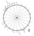
- Figure 3 is a rear view of the seal land assembly.
- Figure 3A is another rear view of another example seal land assembly.
- Figure 4 is a cross-sectional view with a portion of the example seal land assembly.
- Figure 5 is an enlarged view of a portion of the example seal land assembly.
- Figure 6 is another enlarged view of a slot disposed within the example seal land assembly.
- Referring to Figure 1, an example engine assembly 10 includes an
exhaust liner assembly 12. Theexhaust liner assembly 12 includes aninterface 30 to provide for movement of theexhaust liner 12. The engine assembly 10 is disposed within ahousing 15 that includes aninner surface 26. Air enters the engine assembly 10 into acompression module 16. Compressed air from thecompression module 16 is injected into acombustion module 14. In thecombustion module 14, compressed air is mixed with gas and ignited to create hot core exhaust gases that are driven past aturbine module 18. Rotation of theturbine module 18 drives thecompressor module 14. - Hot core exhaust gas is exhausted through an exhaust duct assembly, schematically indicated at 12. The example
exhaust duct assembly 12 includes aliner assembly 24 that defines an inner surface of the exhaust duct assembly. The exampleexhaust duct assembly 12 includes afirst portion 50 and asecond portion 52 that is movable relative to thefirst portion 50. Aninterface 30 between the first portion and thesecond portion 52 includes acavity 32. Thecavity 32 is injected with air that is by-passed around thecompression module 16 to prevent the hot core exhaust gases from impinging into theinterface 30. - As should be appreciated, the engine assembly 10 illustrated is by way of example only and other engine assemblies or moveable duct assemblies requiring a liner will benefit from the disclosures of the invention.
- Referring to Figure 2, the
interface 30 of theexhaust liner assembly 12 includes thefirst portion 50 and thesecond portion 52. Thefirst portion 50 in the exampleexhaust liner assembly 12 is stationary. Thesecond portion 52 is moveable relative to thefirst portion 50. Movement between thefirst portion 50 and thesecond portion 52 is facilitated by a gap between the twoportions cooling air 36. - The
inner surface 28 of thefirst portion 50 is disposed at a different radial position relative to theinner surface 28 of thesecond portion 52. These different radial positions result in a radial distance 34 between the twoinner surfaces 28. This radial distance 34 varies about the circumference of theexhaust duct assembly 12. - The
second portion 52 includes a U-seal 38 that is biased against aseal land 35 by abiasing member 40. The interface between the U-seal 38 and theseal land 35 is biased by thebiasing member 40 to accommodate thermal growth and movement between thefirst portion 50 and thesecond portion 52. Movement between thefirst portion 50 and thesecond portion 52 is facilitated by acavity 32 of theinterface 30.Cooling air flow 36 is injected into thecavity 32 at a rate determined to provide a desired pressure within thecavity 32 that prevents the intrusion ofhot core gases 22. - The
seal land 35 includes aslot 42 through which coolingair 36 flows. Thisslot 42supplies cooling air 36 into a fingerseal injection guide 62 that defines aflow path 64 for the coolingair 36. Thisflow path 64 is defined between a flow pathinner liner 60 and the fingerseal injection guide 62. The end portion of the fingerseal injection guide 62 is held at a desired opening by aspacer 66. - The
slot 42 includes awidth 44 that corresponds with the specific radial distance 34 between the inner surfaces 28. As appreciated, the variation of the radial distance about the circumference of theexhaust liner assembly 12 results in a varying flow out of thecavity 32. The differing air flow out of thecavity 32 in turn, results in differing pressures within thecavity 32. - Conventional accommodation of this variation includes merely injecting cooling air at a sufficient rate to accommodate the cavity and radial distance 34 of the greatest distance thereby providing excessive air flow for some circumferential locations and just enough at other locations. As appreciated, this solution results in the inefficient use of a majority of cooling bypass air.
- The
example seal land 35 includes theslots 42 that vary in size about the circumference of theexhaust liner assembly 12 to tailorair flow 36 to accommodate the localized pressure within thecavity 32 to generate the barrier pressure to thehot core gasses 22. - Referring to Figure 3 with continuing reference to Figure 2, the
seal land 35 is shown and includes a plurality of theslots 42 disposed circumferentially. Between theslots 42 are fastener lands 46. The fastener lands 46 provide a flange surface for attachment of theseal land 35 to theliner portion 50. - The size of the
seal slots 42 vary according to the specific circumferential location within theseal land 35. In theexample seal land 35 theslot width 44 varies every approximately 18 degrees as illustrated at 48. The angular variation is related to the variation in the radial distance 34 about the circumference of theexhaust liner assembly 12. Theslots 42 vary inwidth 44 for eachangular section 48 about the entire circumference of theseal land 35. The variation in slot size customizes and varies the coolingair flow 36 into thecircumferential cavity 32 to accommodate and provide the desired pressure to prevent impingement of thehot core gases 22. - Referring to Figure 3A, another example seal land 35' includes a plurality of
openings 42 that are the same size, but are grouped non-uniformly about the circumference of the seal land 35'. In this way a common size opening can be utilized in desired densities to provide the desired variation of airflow through the seal land 35' in a specific circumferential sector. In the example seal land 35' asector 49 includes a plurality ofslots 42 that are spaced acircumferential length 51 apart. This spacing of slots provides a desired airflow for that specific circumferential area. In contrast, another sector includesslots 42 spaced acircumferential distance 53 apart to provide a different airflow as is desired for that particular circumferential location. - Referring to Figure 4, an enlarged cross-sectional view of a portion of
several slots 42 disposed betweenflange members 54 is shown. Eachflange member 54 is to provide for the attachment by way of a fastener to the fastener lands 46. Also disposed between the fastener lands 46 is astep flange 56 to accommodate and provide a bearing surface between the fastener lands 46 to provide a desired sealing and contact surface. - Referring to Figure 5, an enlarged view of a section between the fastener lands 46 is illustrated with the
step flanges 56. The step flanges 56 are of such a length and depth required to provide the desired cooling air flow through theslots 42 that in turn provides the desired pressurization of thecavity 32 of theinterface 30. - Referring to Figure 6, a still greater enlarged view is shown of the
slot 42 disposed between twostep flanges 56 that provides support of the seal land at various circumferential locations. The size of theslot 42 includes awidth 43 and adepth 45. A thickness 55 in theslot 42 varies dependent on a circumferential position on theseal land 35. Variation of the thickness provides a variation in thedepth 45 from the top of thestep flange 56 and acorresponding fastener land 46 that is utilized to tailor airflow into each circumferential location of theseal land 35. Further, the variation of the thickness 55 changes thedepth 45, but does not change an overall thickness 57 of theseal land 35. The overall thickness of theseal land 35 is maintained about the circumference to provide a desired constant mounting surface and sealing surface for the U-seal 38. Although theexample seal land 35 varies the thickness 55, other dimensions, such as thewidth 43 could be varied to provide the desired slot size required to provide the desired airflow into theinterface 30. - Accordingly, the exhaust liner assembly interface according to this invention provides for the stable maintenance of cavity pressure that generates the desired results of providing a barrier to hot core gasses.
- Although a preferred embodiment of this invention has been disclosed, a worker of ordinary skill in this art would recognize that certain modifications would come within the scope of this invention. For that reason, the following claims should be studied to determine the true scope and content of this invention.
Claims (24)
- A liner assembly (24) comprising:an interface (30) between at least two portions (50, 52) of the liner assembly (24); anda plurality of inlets (42) that supply an airflow into the interface (30), wherein the plurality of inlets (42) provide an airflow that varies along the interface (30) to provide a varying flow field through the interface (30).
- The assembly as recited in claim 1, wherein the plurality of inlets (42) comprises at least one of inlet (42) of a different size than at least one other of the plurality of inlets (42).
- The assembly as recited in claim 1 or 2, wherein the interface (30) comprises a cavity (32) disposed between the at least two portions (50, 52) of the liner assembly (24).
- The assembly as recited in claim 1, 2 or 3, wherein the interface (30) is disposed about an inner periphery of the liner assembly (24), and the airflow varies with a position of the opening along the inner periphery.
- The assembly as recited in any preceding claim, wherein the interface (30) comprises a cavity (32) disposed circumferentially about the hot core gas flow.
- The assembly as recited in any preceding claim, wherein the at least two portions (50, 52) of the liner assembly (24) comprise an inner surface (28) of the liner assembly (24), wherein the at least two portions (50, 52) are spaced a radial distance (34) apart from each other.
- The assembly as recited in claim 6, wherein the radial distance (34) between the at least two portions (50, 52) varies along the interface (30), and the size of each of the plurality of inlets (42) varies selectively responsive to variation in the radial distance (34).
- The assembly as recited in claim 7, wherein the interface (30) is circumferential and the size of the plurality of inlets (42) varies over a circumferential length of the interface (30).
- The assembly as recited in claim 8, wherein the circumferential length comprise a length providing between 15 and 20 degrees of the circumference of the liner assembly (24).
- The assembly as recited in claim 7, wherein the interface (30) is circumferential and the number of the plurality of openings (42) varies about a circumferential length of the interface (30).
- An exhaust liner assembly (24) comprising:a least two liner components (50, 52) defining an inner duct surface (28) for directing a flow of core gases.an interface (30) between the at least two liner components (50, 52) disposed about the inner duct surface (28);a plurality of openings (42) disposed about the inner duct for supplying air flow into the interface (30) at a corresponding plurality of locations, wherein the plurality of openings (42) are provide an airflow varying about the interface.
- The assembly as recited in claim 11, wherein the plurality of openings (42) vary in size about the interface for controlling airflow into the interface (30).
- The assembly as recited in claim 11 or 12, wherein the plurality of openings (42) are grouped unequally about the interface (30) for controlling airflow into the interface (30).
- The assembly as recited in claim 12, wherein the at least two liner components (50, 52) are spaced apart a radial distance (34) along the inner duct surface, wherein the radial distance (34) varies about the inner duct surface, and the size of each of the plurality of openings (42) is related to the radial distance (34) between the at least two liner components (50, 52).
- The assembly as recited in any of claims 11 to 14, wherein the at least two liner components (50, 52) are movable relative to each other.
- The assembly as recited in any of claims 11 to 14, wherein the at least two liner components (50, 52) are fixed relative to each other.
- The assembly as recited in claim 12, wherein the interface (30) comprises a cavity (32), wherein the cavity (32) comprises the plurality of openings (42) for supplying air into the cavity (32), and an outlet in communication with the hot core gases.
- The assembly as recited in claim 14, wherein the size of the plurality of openings (42) varies to provide a desired pressure at the outlet.
- The assembly as recited in claim 17, wherein a pressure desired at the outlet varies in relation to spaced apart radial distance (34) between the at least two liner components (50, 52).
- The assembly as recited in claim 18 or 19, wherein the desired pressure is determined to prevent the flow of hot core gases into the interface (30).
- A seal land (35) comprising:a plurality of inlets (42) that supply an airflow through the seal land (35), wherein at least one portion of the seal land (35) provides a flow field different that another portion of the seal land.
- The seal land as recited in claim 21, wherein the seal land (35) comprises at least one inlet (42) of a different size than another of the plurality of inlets (42).
- The seal land as recited in claim 21 or 22, wherein the at least one portion of the seal land (35) comprises more of the plurality of inlets (42) than said another portion of the seal land (35).
- The seal land as recited in claim 21, 22 or 23 wherein the plurality of inlets (42) are disposed on an inner periphery of the seal land (35) and the airflow varies with a position of the inlet (42) along the inner periphery.
Applications Claiming Priority (1)
| Application Number | Priority Date | Filing Date | Title |
|---|---|---|---|
| US11/491,891 US8201413B2 (en) | 2006-07-24 | 2006-07-24 | Seal land with air injection for cavity purging |
Publications (3)
| Publication Number | Publication Date |
|---|---|
| EP1882822A2 true EP1882822A2 (en) | 2008-01-30 |
| EP1882822A3 EP1882822A3 (en) | 2011-02-23 |
| EP1882822B1 EP1882822B1 (en) | 2015-08-05 |
Family
ID=38198243
Family Applications (1)
| Application Number | Title | Priority Date | Filing Date |
|---|---|---|---|
| EP07252042.2A Active EP1882822B1 (en) | 2006-07-24 | 2007-05-18 | Cooled exhaust liner assembly for a gas turbine |
Country Status (3)
| Country | Link |
|---|---|
| US (2) | US8201413B2 (en) |
| EP (1) | EP1882822B1 (en) |
| JP (1) | JP2008025563A (en) |
Cited By (3)
| Publication number | Priority date | Publication date | Assignee | Title |
|---|---|---|---|---|
| FR2930324A1 (en) * | 2008-04-17 | 2009-10-23 | Snecma Sa | DEVICE FOR COOLING A WALL |
| WO2014126899A1 (en) | 2013-02-17 | 2014-08-21 | United Technologies Corporation | Exhaust liner flange cooling |
| EP2400221A3 (en) * | 2010-06-24 | 2017-12-13 | General Electric Company | Ejector purge of cavity adjacent exhaust flowpath |
Families Citing this family (6)
| Publication number | Priority date | Publication date | Assignee | Title |
|---|---|---|---|---|
| US9016695B2 (en) * | 2011-08-02 | 2015-04-28 | United Technologies Corporation | Gas turbine exhaust nozzle divergent flap seal |
| US9316315B2 (en) * | 2012-03-09 | 2016-04-19 | United Technologies Corporation | Seal assembly |
| US10436063B2 (en) | 2012-08-17 | 2019-10-08 | United Technologies Corporation | Assembly for mounting a turbine engine to an airframe |
| US9631517B2 (en) | 2012-12-29 | 2017-04-25 | United Technologies Corporation | Multi-piece fairing for monolithic turbine exhaust case |
| US10145256B2 (en) * | 2017-04-17 | 2018-12-04 | Rohr, Inc. | Aircraft propulsion system seal assembly with spring seal element and compliant seal element |
| CN116066857A (en) * | 2023-02-14 | 2023-05-05 | 上海慕帆动力科技有限公司 | Combustion nozzle structure and working method of a gas turbine |
Citations (2)
| Publication number | Priority date | Publication date | Assignee | Title |
|---|---|---|---|---|
| US4109864A (en) | 1976-12-23 | 1978-08-29 | General Electric Company | Coolant flow metering device |
| EP1156280A2 (en) | 2000-05-15 | 2001-11-21 | United Technologies Corporation | Gas turbine engine liner |
Family Cites Families (17)
| Publication number | Priority date | Publication date | Assignee | Title |
|---|---|---|---|---|
| US3972475A (en) * | 1975-07-31 | 1976-08-03 | United Technologies Corporation | Nozzle construction providing for thermal growth |
| US4271666A (en) * | 1979-08-20 | 1981-06-09 | Avco Corporation | Integral infrared radiation suppressor for a turbofan engine |
| FR2604750B1 (en) | 1986-10-01 | 1988-12-02 | Snecma | TURBOMACHINE PROVIDED WITH AN AUTOMATIC CONTROL DEVICE FOR TURBINE VENTILATION FLOWS |
| US4718230A (en) | 1986-11-10 | 1988-01-12 | United Technologies Corporation | Augmentor liner construction |
| US4864818A (en) * | 1988-04-07 | 1989-09-12 | United Technologies Corporation | Augmentor liner construction |
| GB9305012D0 (en) | 1993-03-11 | 1993-04-28 | Rolls Royce Plc | Sealing structures for gas turbine engines |
| US5435127A (en) * | 1993-11-15 | 1995-07-25 | General Electric Company | Method and apparatus for boosting ram airflow to an ejection nozzle |
| US5996936A (en) * | 1997-09-29 | 1999-12-07 | General Electric Company | Fluidic throat exhaust nozzle |
| US6295805B1 (en) * | 2000-09-14 | 2001-10-02 | Lockheed Martin Corporation | Exhaust induced ejector nozzle system and method |
| WO2002027148A1 (en) | 2000-09-28 | 2002-04-04 | Siemens Westinghouse Power Corporation | Flexible interlocking combustor transition seal |
| US6792763B2 (en) * | 2002-08-15 | 2004-09-21 | Power Systems Mfg., Llc | Coated seal article with multiple coatings |
| US7270175B2 (en) * | 2004-01-09 | 2007-09-18 | United Technologies Corporation | Extended impingement cooling device and method |
| US7032835B2 (en) * | 2004-01-28 | 2006-04-25 | United Technologies Corporation | Convergent/divergent nozzle with modulated cooling |
| EP1650503A1 (en) * | 2004-10-25 | 2006-04-26 | Siemens Aktiengesellschaft | Method for cooling a heat shield element and a heat shield element |
| US7739872B2 (en) * | 2005-02-14 | 2010-06-22 | United Technologies Corporation | Cooled dual wall liner closeout |
| US7377099B2 (en) * | 2005-05-27 | 2008-05-27 | United Technologies Corporation | System and method for cooling lateral edge regions of a divergent seal of an axisymmetric nozzle |
| US7631503B2 (en) * | 2006-09-12 | 2009-12-15 | Pratt & Whitney Canada Corp. | Combustor with enhanced cooling access |
-
2006
- 2006-07-24 US US11/491,891 patent/US8201413B2/en active Active
-
2007
- 2007-05-11 JP JP2007126252A patent/JP2008025563A/en active Pending
- 2007-05-18 EP EP07252042.2A patent/EP1882822B1/en active Active
-
2012
- 2012-04-04 US US13/438,871 patent/US9803503B2/en active Active
Patent Citations (2)
| Publication number | Priority date | Publication date | Assignee | Title |
|---|---|---|---|---|
| US4109864A (en) | 1976-12-23 | 1978-08-29 | General Electric Company | Coolant flow metering device |
| EP1156280A2 (en) | 2000-05-15 | 2001-11-21 | United Technologies Corporation | Gas turbine engine liner |
Cited By (7)
| Publication number | Priority date | Publication date | Assignee | Title |
|---|---|---|---|---|
| FR2930324A1 (en) * | 2008-04-17 | 2009-10-23 | Snecma Sa | DEVICE FOR COOLING A WALL |
| WO2009138613A1 (en) * | 2008-04-17 | 2009-11-19 | Snecma | Wall cooling device |
| US8561386B2 (en) | 2008-04-17 | 2013-10-22 | Snecma | Wall cooling device |
| EP2400221A3 (en) * | 2010-06-24 | 2017-12-13 | General Electric Company | Ejector purge of cavity adjacent exhaust flowpath |
| WO2014126899A1 (en) | 2013-02-17 | 2014-08-21 | United Technologies Corporation | Exhaust liner flange cooling |
| EP2956648A4 (en) * | 2013-02-17 | 2016-03-09 | United Technologies Corp | COOLING EXHAUST SHOULDER FLANGE |
| US9909532B2 (en) | 2013-02-17 | 2018-03-06 | United Technologies Corporation | Exhaust liner flange cooling |
Also Published As
| Publication number | Publication date |
|---|---|
| US9803503B2 (en) | 2017-10-31 |
| EP1882822A3 (en) | 2011-02-23 |
| US8201413B2 (en) | 2012-06-19 |
| US20080016871A1 (en) | 2008-01-24 |
| US20120207584A1 (en) | 2012-08-16 |
| EP1882822B1 (en) | 2015-08-05 |
| JP2008025563A (en) | 2008-02-07 |
Similar Documents
| Publication | Publication Date | Title |
|---|---|---|
| US9803503B2 (en) | Seal land with air injection for cavity purging | |
| CA2761998C (en) | Improved bearing chamber pressurization system | |
| US11788471B2 (en) | Systems and methods for preventing fuel leakage in a gas turbine engine | |
| CA2688099C (en) | Centrifugal compressor forward thrust and turbine cooling apparatus | |
| US8092146B2 (en) | Active tip clearance control arrangement for gas turbine engine | |
| EP2809909B1 (en) | Gas turbine engine buffer system providing zoned ventilation | |
| US8302407B2 (en) | Ejector controlled twin air source gas turbine pressurizing air system | |
| US20170268371A1 (en) | Boas segmented heat shield | |
| US10113486B2 (en) | Method and system for modulated turbine cooling | |
| EP2375005B1 (en) | Method for controlling turbine blade tip seal clearance | |
| EP2206902A2 (en) | Turbine cooling air from a centrifugal compressor | |
| US20040247429A1 (en) | Gas turbine stator | |
| EP3000967B1 (en) | Gas turbine rotor assembly and method of assembly | |
| US8137075B2 (en) | Compressor impellers, compressor sections including the compressor impellers, and methods of manufacturing | |
| EP3323991B1 (en) | Vane or blade with airfoil piece having radial seal | |
| EP2809910A1 (en) | Gas turbine engine buffer system | |
| EP2912290B1 (en) | High pressure compressor with cooled casing flanges | |
| CN102691532A (en) | System for regulating a cooling fluid within a turbomachine | |
| US10815814B2 (en) | Re-use and modulated cooling from tip clearance control system for gas turbine engine | |
| US8221061B2 (en) | Gas turbine engine with valve for establishing communication between two enclosures | |
| EP3323979B1 (en) | Airfoil with panel having perimeter seal | |
| EP2540984B1 (en) | Impingement Cooled Nozzle Liner | |
| EP3044516B1 (en) | Boss for combustor panel | |
| EP3067521B1 (en) | Turbine vane with baffles having tolerance resistance coverplates | |
| JPH0526944B2 (en) |
Legal Events
| Date | Code | Title | Description |
|---|---|---|---|
| PUAI | Public reference made under article 153(3) epc to a published international application that has entered the european phase |
Free format text: ORIGINAL CODE: 0009012 |
|
| AK | Designated contracting states |
Kind code of ref document: A2 Designated state(s): AT BE BG CH CY CZ DE DK EE ES FI FR GB GR HU IE IS IT LI LT LU LV MC MT NL PL PT RO SE SI SK TR |
|
| AX | Request for extension of the european patent |
Extension state: AL BA HR MK YU |
|
| PUAL | Search report despatched |
Free format text: ORIGINAL CODE: 0009013 |
|
| AK | Designated contracting states |
Kind code of ref document: A3 Designated state(s): AT BE BG CH CY CZ DE DK EE ES FI FR GB GR HU IE IS IT LI LT LU LV MC MT NL PL PT RO SE SI SK TR |
|
| AX | Request for extension of the european patent |
Extension state: AL BA HR MK RS |
|
| RIC1 | Information provided on ipc code assigned before grant |
Ipc: F01D 25/30 20060101ALI20110117BHEP Ipc: F01D 11/00 20060101AFI20070709BHEP Ipc: F02K 1/82 20060101ALI20110117BHEP Ipc: F23R 3/08 20060101ALI20110117BHEP Ipc: F01D 25/12 20060101ALI20110117BHEP |
|
| 17P | Request for examination filed |
Effective date: 20110823 |
|
| AKX | Designation fees paid |
Designated state(s): DE FR GB |
|
| 17Q | First examination report despatched |
Effective date: 20120823 |
|
| GRAP | Despatch of communication of intention to grant a patent |
Free format text: ORIGINAL CODE: EPIDOSNIGR1 |
|
| INTG | Intention to grant announced |
Effective date: 20150422 |
|
| GRAS | Grant fee paid |
Free format text: ORIGINAL CODE: EPIDOSNIGR3 |
|
| GRAA | (expected) grant |
Free format text: ORIGINAL CODE: 0009210 |
|
| AK | Designated contracting states |
Kind code of ref document: B1 Designated state(s): DE FR GB |
|
| REG | Reference to a national code |
Ref country code: GB Ref legal event code: FG4D |
|
| REG | Reference to a national code |
Ref country code: DE Ref legal event code: R096 Ref document number: 602007042423 Country of ref document: DE |
|
| REG | Reference to a national code |
Ref country code: FR Ref legal event code: PLFP Year of fee payment: 10 |
|
| REG | Reference to a national code |
Ref country code: DE Ref legal event code: R097 Ref document number: 602007042423 Country of ref document: DE |
|
| PLBE | No opposition filed within time limit |
Free format text: ORIGINAL CODE: 0009261 |
|
| STAA | Information on the status of an ep patent application or granted ep patent |
Free format text: STATUS: NO OPPOSITION FILED WITHIN TIME LIMIT |
|
| 26N | No opposition filed |
Effective date: 20160509 |
|
| REG | Reference to a national code |
Ref country code: FR Ref legal event code: PLFP Year of fee payment: 11 |
|
| REG | Reference to a national code |
Ref country code: FR Ref legal event code: CA Effective date: 20170324 |
|
| REG | Reference to a national code |
Ref country code: DE Ref legal event code: R082 Ref document number: 602007042423 Country of ref document: DE Representative=s name: SCHMITT-NILSON SCHRAUD WAIBEL WOHLFROM PATENTA, DE |
|
| REG | Reference to a national code |
Ref country code: DE Ref legal event code: R082 Ref document number: 602007042423 Country of ref document: DE Representative=s name: SCHMITT-NILSON SCHRAUD WAIBEL WOHLFROM PATENTA, DE Ref country code: DE Ref legal event code: R081 Ref document number: 602007042423 Country of ref document: DE Owner name: UNITED TECHNOLOGIES CORP. (N.D.GES.D. STAATES , US Free format text: FORMER OWNER: UNITED TECHNOLOGIES CORP., HARTFORD, CONN., US |
|
| REG | Reference to a national code |
Ref country code: FR Ref legal event code: PLFP Year of fee payment: 12 |
|
| REG | Reference to a national code |
Ref country code: DE Ref legal event code: R081 Ref document number: 602007042423 Country of ref document: DE Owner name: RAYTHEON TECHNOLOGIES CORPORATION (N.D.GES.D.S, US Free format text: FORMER OWNER: UNITED TECHNOLOGIES CORP. (N.D.GES.D. STAATES DELAWARE), FARMINGTON, CONN., US Ref country code: DE Ref legal event code: R081 Ref document number: 602007042423 Country of ref document: DE Owner name: RTX CORPORATION (N.D.GES.D. STAATES DELAWARE),, US Free format text: FORMER OWNER: UNITED TECHNOLOGIES CORP. (N.D.GES.D. STAATES DELAWARE), FARMINGTON, CONN., US |
|
| P01 | Opt-out of the competence of the unified patent court (upc) registered |
Effective date: 20230519 |
|
| PGFP | Annual fee paid to national office [announced via postgrant information from national office to epo] |
Ref country code: DE Payment date: 20250423 Year of fee payment: 19 |
|
| PGFP | Annual fee paid to national office [announced via postgrant information from national office to epo] |
Ref country code: GB Payment date: 20250423 Year of fee payment: 19 |
|
| PGFP | Annual fee paid to national office [announced via postgrant information from national office to epo] |
Ref country code: FR Payment date: 20250423 Year of fee payment: 19 |
|
| REG | Reference to a national code |
Ref country code: DE Ref legal event code: R081 Ref document number: 602007042423 Country of ref document: DE Owner name: RTX CORPORATION (N.D.GES.D. STAATES DELAWARE),, US Free format text: FORMER OWNER: RAYTHEON TECHNOLOGIES CORPORATION (N.D.GES.D.STAATES DELAWARE), ARLINGTON, VA, US |