EP1882630A1 - Unit and method of feeding containers arranged in a number of superimposed rows - Google Patents
Unit and method of feeding containers arranged in a number of superimposed rows Download PDFInfo
- Publication number
- EP1882630A1 EP1882630A1 EP07120935A EP07120935A EP1882630A1 EP 1882630 A1 EP1882630 A1 EP 1882630A1 EP 07120935 A EP07120935 A EP 07120935A EP 07120935 A EP07120935 A EP 07120935A EP 1882630 A1 EP1882630 A1 EP 1882630A1
- Authority
- EP
- European Patent Office
- Prior art keywords
- slide surface
- containers
- feed unit
- path
- packets
- Prior art date
- Legal status (The legal status is an assumption and is not a legal conclusion. Google has not performed a legal analysis and makes no representation as to the accuracy of the status listed.)
- Withdrawn
Links
- 238000000034 method Methods 0.000 title claims description 11
- 235000019504 cigarettes Nutrition 0.000 claims description 40
- 238000012856 packing Methods 0.000 claims description 10
- 239000000463 material Substances 0.000 claims description 6
- 238000005485 electric heating Methods 0.000 claims description 4
- 229920003023 plastic Polymers 0.000 claims description 4
- 125000004122 cyclic group Chemical group 0.000 claims description 3
- 238000010438 heat treatment Methods 0.000 description 3
- 238000004519 manufacturing process Methods 0.000 description 3
- 238000004806 packaging method and process Methods 0.000 description 3
- 230000005540 biological transmission Effects 0.000 description 2
- 239000000945 filler Substances 0.000 description 2
- 239000011888 foil Substances 0.000 description 2
- 238000011144 upstream manufacturing Methods 0.000 description 2
- 239000006096 absorbing agent Substances 0.000 description 1
- 230000009977 dual effect Effects 0.000 description 1
- 229920001971 elastomer Polymers 0.000 description 1
- 239000000806 elastomer Substances 0.000 description 1
- 235000013305 food Nutrition 0.000 description 1
- 230000005484 gravity Effects 0.000 description 1
- 230000000284 resting effect Effects 0.000 description 1
- 230000035939 shock Effects 0.000 description 1
Images



Classifications
-
- B—PERFORMING OPERATIONS; TRANSPORTING
- B65—CONVEYING; PACKING; STORING; HANDLING THIN OR FILAMENTARY MATERIAL
- B65B—MACHINES, APPARATUS OR DEVICES FOR, OR METHODS OF, PACKAGING ARTICLES OR MATERIALS; UNPACKING
- B65B53/00—Shrinking wrappers, containers, or container covers during or after packaging
- B65B53/02—Shrinking wrappers, containers, or container covers during or after packaging by heat
-
- B—PERFORMING OPERATIONS; TRANSPORTING
- B65—CONVEYING; PACKING; STORING; HANDLING THIN OR FILAMENTARY MATERIAL
- B65B—MACHINES, APPARATUS OR DEVICES FOR, OR METHODS OF, PACKAGING ARTICLES OR MATERIALS; UNPACKING
- B65B19/00—Packaging rod-shaped or tubular articles susceptible to damage by abrasion or pressure, e.g. cigarettes, cigars, macaroni, spaghetti, drinking straws or welding electrodes
- B65B19/28—Control devices for cigarette or cigar packaging machines
-
- B—PERFORMING OPERATIONS; TRANSPORTING
- B65—CONVEYING; PACKING; STORING; HANDLING THIN OR FILAMENTARY MATERIAL
- B65B—MACHINES, APPARATUS OR DEVICES FOR, OR METHODS OF, PACKAGING ARTICLES OR MATERIALS; UNPACKING
- B65B35/00—Supplying, feeding, arranging or orientating articles to be packaged
- B65B35/56—Orientating, i.e. changing the attitude of, articles, e.g. of non-uniform cross-section
- B65B35/58—Turning articles by positively-acting means, e.g. to present labelled portions in uppermost position
Definitions
- the present invention relates to a unit and method of feeding containers arranged in a number of superimposed rows.
- the present invention may be used to particular advantage on a cigarette packing line, to which the following description refers purely by way of example.
- a cigarette packing line normally comprises a manufacturing machine for producing the cigarettes; a filter assembly machine for applying filters to the cigarettes; a packing machine for producing soft or rigid packets of cigarettes; a cellophaning machine for applying an overwrapping of transparent plastic material to the packets of cigarettes; and a cartoning machine for producing cartons of packets of cigarettes.
- a feed unit is interposed between the cellophaning machine and the cartoning machine to receive a succession of packets of cigarettes from an output of the cellophaning machine and transfer the succession of packets of cigarettes to an input of the cartoning machine.
- the feed unit often has a reject station located along the path of the packets of cigarettes to remove from the path any faulty packets of cigarettes detected by control stations on the cellophaning machine. Location of the reject station at the feed unit is usually advantageous on account of the considerable size of the reject station, which must also collect the rejected packets of cigarettes and is difficult to accommodate on the cellophaning machine.
- Some known packing lines of the type described above are designed to transfer from the output of the cellophaning machine to the input of the cartoning machine a succession of packets of cigarettes arranged in two or more superimposed rows, so as to reduce the average travelling speed, and hence mechanical stress, of the packets of cigarettes.
- rejection of a faulty packet of cigarettes travelling through the reject station calls for also rejecting the good packet/s stacked with it. This is due to the way in which known reject stations are built and operate, which does not permit removal from the stream of a single packet stacked with another.
- the feed unit may also comprise a heat-shrink station for heat treating each packet of cigarettes.
- the heat-shrink station For each row of packets of cigarettes, the heat-shrink station comprises a respective channel, along which the row of packets of cigarettes travels in use, and which is bounded at the top and bottom by two slide surfaces equipped with electric heating elements.
- the major lateral walls of the packet of cigarettes inevitably slide along the heated slide surfaces, thus generating friction on the packet of cigarettes, which is a function of the pressure exerted on the packet by the slide surfaces.
- the slide surfaces are spaced far apart. Such a solution, however, reduces the effectiveness of the heat treatment and calls for using very long heat-shrink stations.
- EP1084954A1 discloses an apparatus for manufacturing hinged-lid boxes for cigarettes, in which a packaging carton is enclosed by foil sheet which is folded around its outside and folded flaps are welded together by application of heat, before subsequent heat treatment for shrinking foil to form tight fit; the packaging cartons are transported in two rows along a straight transport path, with indexed movement to heat the shrink station with heating plates for application of heat to the outer surfaces of each packaging carton.
- EP1103465 discloses an apparatus for manufacturing hinged-lid boxes for cigarettes, in which the cigarette box producing process produces packs from thin card with an outer cover of shrink wrap; the folding tabs of the outer cover are bonded to each other by full-surface thermal seals and the head of this process shrinks the wrap.
- Number 1 in Figure 1 indicates as a whole a feed unit for feeding containers or packets 2 of cigarettes arranged in two superimposed, respectively bottom and top, rows 3 and 4.
- Feed unit 1 forms part of a cigarette packing line comprising a cellophaning machine 5 for applying an overwrapping of transparent plastic material to packets 2 of cigarettes; and a cartoning machine 6 for producing cartons of packets 2 of cigarettes. More specifically, feed unit 1 is interposed between cellophaning machine 5 and cartoning machine 6, receives a succession of packets 2 of cigarettes from an output 7 of cellophaning machine 5, and transfers the succession of packets 2 of cigarettes to an input 8 of cartoning machine 6.
- Feed unit 1 comprises a conveying device 9 for feeding packets 2 along a horizontal U-shaped path P extending from output 7 of cellophaning machine 5 to input 8 of cartoning machine 6. More specifically, path P comprises a linear start portion P1; a linear intermediate portion P2 perpendicular to start portion P1; and a linear end portion P3 parallel to start portion P1.
- Conveying device 9 comprises a U-shaped slide surface 10 parallel to path P and for supporting packets 2 in sliding manner; and a push device 11 for pushing packets 2 along slide surface 10.
- Push device 11 comprises a pusher 12 having a number of push members 13 fitted to an endless belt 14 (shown only partly), and which pushes packets 2 along start portion P1; a pusher 15 having a 16 with a linear reciprocating movement, and which pushes packets 2 along intermediate portion P2; and a pusher 17 having a number of push members 18 fitted to an endless belt 19, and which pushes packets 2 along end portion P3.
- a heat-shrink station S1 for heat treating each packet 2, and a reject station S2, for expelling any faulty packets 2 from path P, are arranged in succession along intermediate portion P2 of path P.
- a stacking station S4 Immediately downstream from reject station S2, and therefore downstream from heat-shrink station S1, is located a stacking station S4 where two facing packets 2 are brought back into contact with each other by translation in a vertical direction D, so as to travel, superimposed, along the next portion of path P.
- rows 3 and 4 of packets 2 travel, superimposed, along path P with the exception of the portion of intermediate portion P2 of path P extending between parting station S3 and stacking station S4; along which portion, rows 3 and 4 of packets 2 are fed parted and facing each other by conveying device 9, and in particular pusher 15.
- Heat-shrink station S1 comprises a further two slide surfaces 20 and 21, which are parallel to and face slide surface 10 to define, with slide surface 10, two channels 22 and 23, along which respective rows 3 and 4 of packets 2 are fed. More specifically, the bottom row 3 of packets slides along slide surface 10 and inside channel 22 defined between slide surface 10 and slide surface 20, while the top row 4 of packets slides along slide surface 20 and inside channel 23 defined between slide surface 20 and slide surface 21.
- Slide surfaces 10, 20, 21 comprise electric heating elements (not shown), which are embedded inside slide surfaces 10, 20, 21 and controlled to heat channels 22, 23 to a given temperature, which normally depends on the travelling speed of packets 2 along path P, and on the type of plastic overwrapping material (not shown) applied to packets 2.
- slide surfaces 10 and 21 at heat-shrink station S1 are movable in a vertical direction D perpendicular to path P
- heat-shrink station S1 comprises two actuating devices 24 for moving slide surfaces 10 and 21 cyclically in vertical direction D perpendicular to path P, so as to move slide surfaces 10 and 21 cyclically towards and away from slide surface 20.
- both actuating devices 24 form part of the same mechanism, i.e. are powered by a common motor.
- the two actuating devices 24 are mechanically independent.
- conveying device 9 feeds packets 2 along path P with an intermittent movement comprising a cyclic succession of travelling steps and hold steps.
- actuating devices 24 are timed with conveying device 9 to keep slide surfaces 10 and 21 close to slide surface 20 during the hold steps, and away from slide surface 20 during the travelling steps in the intermittent movement. This has the dual effect of permitting unimpeded travel of packets 2 along path P, and increasing heat transmission to packets 2 by virtue of sliding surfaces 10, 20, 21 firmly contacting packets 2.
- an elastic member 24a is therefore preferably interposed to allow a certain amount of flexible self-adjustment of the position of slide surface 10, 21 in vertical direction D. This is particularly useful by enabling slide surfaces 10 and 21 to adapt automatically to the actual size of packets 2.
- each elastic member 24a interposed between each actuating device 24 and respective slide surface 10, 21 is defined by a spring, a pneumatic shock absorber, or an elastomer.
- Reject station S2 comprises a reject device 25 for only expelling one bottom packet 2, i.e. in bottom row 3 of packets 2, from path P; and a reject device 26 for only expelling one top packet 2, i.e. in top row 4 of packets 2, from path P.
- Each reject device 25, 26 preferably comprises a pneumatic push device (not shown in detail) for pushing a packet 2 off path P in a horizontal direction perpendicular to path P.
- Slide surface 20 ends at stacking station S4, so that the packets 2 in top row 4 travelling along slide surface 20 are eventually unsupported from underneath and drop by force of gravity onto packets 2 in bottom row 3.
- stacking station S4 comprises a supporting surface 27 movable, in a vertical direction D perpendicular to path P, between a withdrawn position, in which a top face of supporting surface 27 is aligned with a top face of slide surface 10, and a raised position, in which the top face of supporting surface 27 is raised with respect to the top face of slide surface 10.
- Parting station S3 comprises a supporting surface 28 movable, in a vertical direction D perpendicular to path P, between a withdrawn position, in which a top face of supporting surface 28 is aligned with a top face of slide surface 10, and a raised position, in which the top face of supporting surface 28 is raised with respect to the top face of slide surface 10 and aligned with a top face of slide surface 20.
- Parting station S3 also comprises a clamping device 29 aligned vertically with supporting surface 28 and for clamping a packet 2 in a given vertical position slightly above slide surface 20.
- clamping device 29 comprises a suction member (not shown).
- clamping device 29 comprises a gripper (not shown) having two jaws movable in a direction crosswise to path P and in opposition to elastic means.
- a known filler station S5 is located downstream from reject station S2 to transfer a number of packets 2 to conveying device 9 to replace any packets 2 expelled at reject station S2.
- Filler station S5 comprises a vertical hopper 30 containing a stack of superimposed packets 2 and having an outlet located over conveying device 9.
- conveying device 9 preferably comprises a rotation station S6 for rotating each packet 2 by 180° about a vertical axis 31 perpendicular to path P.
- Rotation station S6 comprises a horizontal turntable 32 having four vertical members 33 projecting upwards from turntable 32 and arranged to enclose packets 2.
- Reject station S2 as described above has numerous advantages by enabling, even in the case of packets of cigarettes arranged in two or more superimposed rows, rejection of either all or only one of the packets in a given stack, regardless of the location of the rejected packet.
- Heat-shrink station S1 as described above has numerous advantages by permitting unimpeded travel of packets 2 along path P, while at the same time increasing heat transmission to packets 2 by virtue of slide surfaces 10, 20, 21 firmly contacting packets 2.
- feed unit 1 as described above may also be used to advantage at other points along a cigarette packing line, or even on other automatic machines for packing other than cigarettes (e.g. food products).
Landscapes
- Engineering & Computer Science (AREA)
- Mechanical Engineering (AREA)
- Wrapping Of Specific Fragile Articles (AREA)
- Container Filling Or Packaging Operations (AREA)
- Auxiliary Devices For And Details Of Packaging Control (AREA)
- Supplying Of Containers To The Packaging Station (AREA)
- Stacking Of Articles And Auxiliary Devices (AREA)
Abstract
Description
- The present invention relates to a unit and method of feeding containers arranged in a number of superimposed rows.
- The present invention may be used to particular advantage on a cigarette packing line, to which the following description refers purely by way of example.
- A cigarette packing line normally comprises a manufacturing machine for producing the cigarettes; a filter assembly machine for applying filters to the cigarettes; a packing machine for producing soft or rigid packets of cigarettes; a cellophaning machine for applying an overwrapping of transparent plastic material to the packets of cigarettes; and a cartoning machine for producing cartons of packets of cigarettes.
- A feed unit is interposed between the cellophaning machine and the cartoning machine to receive a succession of packets of cigarettes from an output of the cellophaning machine and transfer the succession of packets of cigarettes to an input of the cartoning machine. The feed unit often has a reject station located along the path of the packets of cigarettes to remove from the path any faulty packets of cigarettes detected by control stations on the cellophaning machine. Location of the reject station at the feed unit is usually advantageous on account of the considerable size of the reject station, which must also collect the rejected packets of cigarettes and is difficult to accommodate on the cellophaning machine.
- Some known packing lines of the type described above are designed to transfer from the output of the cellophaning machine to the input of the cartoning machine a succession of packets of cigarettes arranged in two or more superimposed rows, so as to reduce the average travelling speed, and hence mechanical stress, of the packets of cigarettes.
- When feeding packets of cigarettes arranged in two or more superimposed rows, rejection of a faulty packet of cigarettes travelling through the reject station calls for also rejecting the good packet/s stacked with it. This is due to the way in which known reject stations are built and operate, which does not permit removal from the stream of a single packet stacked with another.
- The feed unit may also comprise a heat-shrink station for heat treating each packet of cigarettes. For each row of packets of cigarettes, the heat-shrink station comprises a respective channel, along which the row of packets of cigarettes travels in use, and which is bounded at the top and bottom by two slide surfaces equipped with electric heating elements. When a packet of cigarettes is pushed along the respective channel at the heat-shrink station, the major lateral walls of the packet of cigarettes inevitably slide along the heated slide surfaces, thus generating friction on the packet of cigarettes, which is a function of the pressure exerted on the packet by the slide surfaces. To avoid subjecting the packet of cigarettes to severe friction which might damage or even tear the sheet of overwrapping material, the slide surfaces are spaced far apart. Such a solution, however, reduces the effectiveness of the heat treatment and calls for using very long heat-shrink stations.
-
EP1084954A1 discloses an apparatus for manufacturing hinged-lid boxes for cigarettes, in which a packaging carton is enclosed by foil sheet which is folded around its outside and folded flaps are welded together by application of heat, before subsequent heat treatment for shrinking foil to form tight fit; the packaging cartons are transported in two rows along a straight transport path, with indexed movement to heat the shrink station with heating plates for application of heat to the outer surfaces of each packaging carton. -
EP1103465 discloses an apparatus for manufacturing hinged-lid boxes for cigarettes, in which the cigarette box producing process produces packs from thin card with an outer cover of shrink wrap; the folding tabs of the outer cover are bonded to each other by full-surface thermal seals and the head of this process shrinks the wrap. - It is an object of the present invention to provide a unit and method of feeding containers arranged in a number of superimposed rows, which unit and method are designed to eliminate the aforementioned drawbacks and, in particular, are cheap and easy to implement.
- According to the present invention, there are provided a unit and method of feeding containers arranged in a number of superimposed rows, as claimed in the accompanying Claims.
- A non-limiting embodiment of the present invention will be described by way of example with reference to the accompanying drawings, in which:
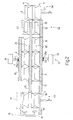
- Figure 1 shows a schematic plan view, with parts removed for clarity, of a feed unit in accordance with the present invention and located between an output of a cellophaning machine and the input of a cartoning machine;
- Figure 2 shows a schematic lateral section of part of the Figure 1 feed unit;
- Figures 3 to 5 show schematic lateral sections of three instants in the operation of a parting station of the Figure 1 feed unit;
- Figure 6 shows a schematic plan view of a rotation station of the Figure 1 feed unit.
-
Number 1 in Figure 1 indicates as a whole a feed unit for feeding containers orpackets 2 of cigarettes arranged in two superimposed, respectively bottom and top,rows unit 1 forms part of a cigarette packing line comprising a cellophaning machine 5 for applying an overwrapping of transparent plastic material topackets 2 of cigarettes; and acartoning machine 6 for producing cartons ofpackets 2 of cigarettes. More specifically,feed unit 1 is interposed between cellophaning machine 5 andcartoning machine 6, receives a succession ofpackets 2 of cigarettes from anoutput 7 of cellophaning machine 5, and transfers the succession ofpackets 2 of cigarettes to aninput 8 ofcartoning machine 6. -
Feed unit 1 comprises aconveying device 9 forfeeding packets 2 along a horizontal U-shaped path P extending fromoutput 7 of cellophaning machine 5 to input 8 ofcartoning machine 6. More specifically, path P comprises a linear start portion P1; a linear intermediate portion P2 perpendicular to start portion P1; and a linear end portion P3 parallel to start portion P1. -
Conveying device 9 comprises aU-shaped slide surface 10 parallel to path P and for supportingpackets 2 in sliding manner; and apush device 11 for pushingpackets 2 alongslide surface 10.Push device 11 comprises apusher 12 having a number ofpush members 13 fitted to an endless belt 14 (shown only partly), and which pushespackets 2 along start portion P1; apusher 15 having a 16 with a linear reciprocating movement, and which pushespackets 2 along intermediate portion P2; and apusher 17 having a number ofpush members 18 fitted to anendless belt 19, and which pushespackets 2 along end portion P3. - As shown in Figure 2, a heat-shrink station S1, for heat treating each
packet 2, and a reject station S2, for expelling anyfaulty packets 2 from path P, are arranged in succession along intermediate portion P2 of path P. - Upstream from heat-shrink station S1, and therefore upstream from reject station S2, is located a parting station S3 where two
superimposed packets 2 are parted by translation in a vertical direction D perpendicular to path P, so as to travel separately and facing each other along the next portion of path P. Immediately downstream from reject station S2, and therefore downstream from heat-shrink station S1, is located a stacking station S4 where two facingpackets 2 are brought back into contact with each other by translation in a vertical direction D, so as to travel, superimposed, along the next portion of path P. - In other words,
rows packets 2 travel, superimposed, along path P with the exception of the portion of intermediate portion P2 of path P extending between parting station S3 and stacking station S4; along which portion,rows packets 2 are fed parted and facing each other by conveyingdevice 9, and inparticular pusher 15. - Heat-shrink station S1 comprises a further two
slide surfaces face slide surface 10 to define, withslide surface 10, twochannels respective rows packets 2 are fed. More specifically, thebottom row 3 of packets slides alongslide surface 10 and insidechannel 22 defined betweenslide surface 10 andslide surface 20, while thetop row 4 of packets slides alongslide surface 20 and insidechannel 23 defined betweenslide surface 20 andslide surface 21. -
Slide surfaces slide surfaces heat channels packets 2 along path P, and on the type of plastic overwrapping material (not shown) applied topackets 2. - In a preferred embodiment,
slide surfaces actuating devices 24 for movingslide surfaces slide surfaces slide surface 20. In a preferred embodiment, both actuatingdevices 24 form part of the same mechanism, i.e. are powered by a common motor. In an alternative embodiment, the twoactuating devices 24 are mechanically independent. - More specifically, conveying
device 9feeds packets 2 along path P with an intermittent movement comprising a cyclic succession of travelling steps and hold steps. And actuatingdevices 24 are timed withconveying device 9 to keepslide surfaces slide surface 20 during the hold steps, and away fromslide surface 20 during the travelling steps in the intermittent movement. This has the dual effect of permitting unimpeded travel ofpackets 2 along path P, and increasing heat transmission topackets 2 by virtue ofsliding surfaces packets 2. - The actual size of
packets 2 varies fairly widely on account of inevitable tolerances as regards both materials and packing processes. Between eachactuating device 24 andrespective slide surface elastic member 24a is therefore preferably interposed to allow a certain amount of flexible self-adjustment of the position ofslide surface slide surfaces packets 2. - In other words, by means of
elastic members 24a, substantially constant pressure is applied on eachpacket 2 regardless of the actual size ofpacket 2. - By way of example, each
elastic member 24a interposed between each actuatingdevice 24 andrespective slide surface - Reject station S2 comprises a
reject device 25 for only expelling onebottom packet 2, i.e. inbottom row 3 ofpackets 2, from path P; and areject device 26 for only expelling onetop packet 2, i.e. intop row 4 ofpackets 2, from path P. Eachreject device packet 2 off path P in a horizontal direction perpendicular to path P. -
Slide surface 20 ends at stacking station S4, so that thepackets 2 intop row 4 travelling alongslide surface 20 are eventually unsupported from underneath and drop by force of gravity ontopackets 2 inbottom row 3. In the event apacket 2 inbottom row 3 is expelled at reject station S2, thecorresponding packet 2 intop row 4 would have too far to fall at stacking station S4 and may become misaligned, so stacking station S4 comprises a supportingsurface 27 movable, in a vertical direction D perpendicular to path P, between a withdrawn position, in which a top face of supportingsurface 27 is aligned with a top face ofslide surface 10, and a raised position, in which the top face of supportingsurface 27 is raised with respect to the top face ofslide surface 10. - When a
packet 2 inbottom row 3 and acorresponding packet 2 intop row 4 are both present, supportingsurface 27 is maintained in the withdrawn position, and, at the end ofslide surface 20,packet 2 intop row 4 drops a short distance vertically ontopacket 2 inbottom row 3. When only apacket 2 intop row 4 is present, with nocorresponding packet 2 inbottom row 3, supportingsurface 27 is moved into the raised position to break the free fall ofpacket 2 intop row 4 and guidepacket 2 down in controlled manner as supportingsurface 27 moves back down into the withdrawn position. - Parting station S3 comprises a supporting
surface 28 movable, in a vertical direction D perpendicular to path P, between a withdrawn position, in which a top face of supportingsurface 28 is aligned with a top face ofslide surface 10, and a raised position, in which the top face of supportingsurface 28 is raised with respect to the top face ofslide surface 10 and aligned with a top face ofslide surface 20. Parting station S3 also comprises aclamping device 29 aligned vertically with supportingsurface 28 and for clamping apacket 2 in a given vertical position slightly aboveslide surface 20. In one embodiment,clamping device 29 comprises a suction member (not shown). In an alternative embodiment,clamping device 29 comprises a gripper (not shown) having two jaws movable in a direction crosswise to path P and in opposition to elastic means. - In actual use, and as shown in Figures 3 to 5, when a
packet 2 inbottom row 3 and acorresponding packet 2 intop row 4 reach parting station S3, supportingsurface 28 is moved from the withdrawn to the raised position to lift bothpacket 2 inbottom row 3 andcorresponding packet 2 intop row 4 and bringpacket 2 intop row 4 into contact withclamping device 29. At this point,packet 2 intop row 4 remains in contact withclamping device 29, and, as supportingsurface 28 moves back down into the withdrawn position, is parted frompacket 2 in bottom row 3 (resting on supporting surface 28). - As shown in Figure 1, a known filler station S5 is located downstream from reject station S2 to transfer a number of
packets 2 to conveyingdevice 9 to replace anypackets 2 expelled at reject station S2. Filler station S5 comprises avertical hopper 30 containing a stack ofsuperimposed packets 2 and having an outlet located overconveying device 9. - As shown in Figure 6,
conveying device 9 preferably comprises a rotation station S6 for rotating eachpacket 2 by 180° about a vertical axis 31 perpendicular to path P. Rotation station S6 comprises ahorizontal turntable 32 having fourvertical members 33 projecting upwards fromturntable 32 and arranged to enclosepackets 2. - Reject station S2 as described above has numerous advantages by enabling, even in the case of packets of cigarettes arranged in two or more superimposed rows, rejection of either all or only one of the packets in a given stack, regardless of the location of the rejected packet.
- Heat-shrink station S1 as described above has numerous advantages by permitting unimpeded travel of
packets 2 along path P, while at the same time increasing heat transmission topackets 2 by virtue ofslide surfaces packets 2. - Given its numerous advantages,
feed unit 1 as described above may also be used to advantage at other points along a cigarette packing line, or even on other automatic machines for packing other than cigarettes (e.g. food products).
Claims (9)
- A feed unit for feeding containers arranged in a number of superimposed rows;
the feed unit (1) comprises conveying means (9) for feeding the containers (2), arranged in at least two superimposed rows (3, 4), along a horizontal path (P), and a heat-shrink station (S1) for heat treating each container (2);
the heat-shrink station (S1) comprises a first slide surface (10) parallel to the path (P) and for supporting in sliding manner the containers (2) in a bottom row (3), a second slide surface (20) parallel to and facing the first slide surface (10) and for supporting in sliding manner the containers (2) in a top row (4), and a third slide surface (21) parallel to and facing the second slide surface (20);
a first heated channel (22), along which the bottom row (3) of containers (2) travels, is defined between the first slide surface (10) and the second slide surface (20);
a second heated channel (23), along which the top row (4) of containers (2) travels, is defined between the second slide surface (20) and the third slide surface (21); and
the feed unit (1) is characterized by comprising actuating means (24) for moving the first and third slide surface (10, 21) cyclically in a vertical direction (D) perpendicular to the path (P), so as to move the first and third slide surface (10, 21) cyclically towards and away from the second slide surface (20). - A feed unit (1) as claimed in Claim 1, wherein the conveying means (9) feed the containers (2) along the path (P) with an intermittent movement comprising a cyclic succession of travelling steps and hold steps; and the actuating means (24) are timed with the conveying means (9) to keep the first and third slide surface (10, 21) close to the second slide surface (20) during the hold steps in the intermittent movement, and to keep the first and third slide surface (10, 21) away from the second slide surface (20) during the travelling steps in the intermittent movement.
- A feed unit (1) as claimed in Claim 1 or 2, wherein the slide surfaces comprise electric heating elements.
- A feed unit (1) as claimed in Claim 1, 2 or 3, wherein respective elastic members (24a) are interposed between the actuating means (24) and the first and third slide surface (10, 21) to permit elastic self-adjustment of the position of the first and third slide surface (10, 21) in the vertical direction (D).
- A cigarette packing line comprising a cellophaning machine (5) for applying respective overwrappings of transparent plastic material to packets (2) of cigarettes, a cartoning machine (6) for producing cartons of packets of cigarettes, and a feed unit (1) interposed between the cellophaning machine (5) and the cartoning machine (6) to receive a succession of packets of cigarettes from an output of the cellophaning machine (5) and transfer the succession of packets of cigarettes to an input of the cartoning machine (6); the packing line being characterized in that the feed unit (1) is of the type claimed in Claims 1, 2 or 3.
- A method of feeding containers arranged in a number of superimposed rows;
the method comprises the step of feeding the containers (2), arranged in at least two superimposed rows (3, 4), along a horizontal path (P) and through a heat-shrink station (S1) for heat treating each container (2);
the heat-shrink station (S1) comprises a first slide surface (10) parallel to the path (P) and for supporting in sliding manner the containers (2) in a bottom row (3), a second slide surface (20) parallel to and facing the first slide surface (10) and for supporting in sliding manner the containers (2) in a top row (4), and a third slide surface (21) parallel to and facing the second slide surface (20);
a first heated channel (22), along which the bottom row (3) of containers (2) travels, is defined between the first slide surface (10) and the second slide surface (20);
a second heated channel (23), along which the top row (4) of containers (2) travels, is defined between the second slide surface (20) and the third slide surface (21); and
the method is characterized by comprising the further step of moving the first and third slide surface (10, 21) cyclically in a vertical direction (D) perpendicular to the path (P), so as to move the first and third slide surface (10, 21) cyclically towards and away from the second slide surface (20). - A feed unit (1) as claimed in Claim 6 and comprising the further steps of:feeding the containers (2) along the path (P) by means of conveying means (9) and with an intermittent movement comprising a cyclic succession of travelling steps and hold steps; andtiming the actuating means (24) with the conveying means (9) to keep the first and third slide surface (10, 21) close to the second slide surface (20) during the hold steps in the intermittent movement, and to keep the first and third slide surface (10, 21) away from the second slide surface (20) during the travelling steps in the intermittent movement.
- A feed unit (1) as claimed in Claim 6 or 7, wherein the slide surfaces comprise electric heating elements.
- A feed unit (1) as claimed in Claim 6, 7 or 8, wherein respective elastic members (24a) are interposed between the actuating means (24) and the first and third slide surface (10, 21) to permit elastic self-adjustment of the position of the first and third slide surface (10, 21) in the vertical direction (D).
Applications Claiming Priority (2)
| Application Number | Priority Date | Filing Date | Title |
|---|---|---|---|
| IT000671A ITBO20040671A1 (en) | 2004-10-28 | 2004-10-28 | UNIT AND METHOD OF FEEDING CONTAINERS AVAILABLE ON MORE OVERLAPPED FILES |
| EP05103558A EP1652772B1 (en) | 2004-10-28 | 2005-04-29 | Unit and method of feeding containers arranged in a number of superimposed rows |
Related Parent Applications (1)
| Application Number | Title | Priority Date | Filing Date |
|---|---|---|---|
| EP05103558A Division EP1652772B1 (en) | 2004-10-28 | 2005-04-29 | Unit and method of feeding containers arranged in a number of superimposed rows |
Publications (1)
| Publication Number | Publication Date |
|---|---|
| EP1882630A1 true EP1882630A1 (en) | 2008-01-30 |
Family
ID=34979060
Family Applications (2)
| Application Number | Title | Priority Date | Filing Date |
|---|---|---|---|
| EP07120935A Withdrawn EP1882630A1 (en) | 2004-10-28 | 2005-04-29 | Unit and method of feeding containers arranged in a number of superimposed rows |
| EP05103558A Expired - Lifetime EP1652772B1 (en) | 2004-10-28 | 2005-04-29 | Unit and method of feeding containers arranged in a number of superimposed rows |
Family Applications After (1)
| Application Number | Title | Priority Date | Filing Date |
|---|---|---|---|
| EP05103558A Expired - Lifetime EP1652772B1 (en) | 2004-10-28 | 2005-04-29 | Unit and method of feeding containers arranged in a number of superimposed rows |
Country Status (7)
| Country | Link |
|---|---|
| US (2) | US7337597B2 (en) |
| EP (2) | EP1882630A1 (en) |
| JP (1) | JP2006124032A (en) |
| CN (2) | CN1768609A (en) |
| AT (1) | ATE386684T1 (en) |
| DE (1) | DE602005004862T2 (en) |
| IT (1) | ITBO20040671A1 (en) |
Families Citing this family (10)
| Publication number | Priority date | Publication date | Assignee | Title |
|---|---|---|---|---|
| ITBO20050188A1 (en) * | 2005-03-24 | 2005-06-23 | Gd Spa | METHOD AND DEVICE FOR FINISHING PACKAGES PROVIDED WITH RESPECTIVE THIRD PARTIES OF THERMORESTRINGENT MATERIAL |
| DE102005046304A1 (en) | 2005-09-27 | 2007-03-29 | Focke & Co.(Gmbh & Co. Kg) | Box-shaped package e.g. cigarette package, heat treatment method for use in packaging machine, involves subjecting box-shaped packages with heat in area of upwardly or downwardly directed front side or rear side of packages |
| DE102006024559A1 (en) | 2006-05-23 | 2007-11-29 | Focke & Co.(Gmbh & Co. Kg) | Method and device for producing cigarette packets |
| EP2457834B1 (en) | 2010-11-26 | 2016-04-06 | Swedish Match North Europe AB | Device for positioning of portion packets |
| DK2457833T3 (en) * | 2010-11-26 | 2013-05-27 | Swedish Match North Europe Ab | Device for positioning portion packages |
| CN103600881B (en) * | 2013-11-11 | 2015-07-15 | 南京新路机电设备有限责任公司 | Automatic cigarette bar supplementing system of GD cigarette bar transparent paper packager |
| CN104085555B (en) * | 2014-07-01 | 2017-01-18 | 北京天申正祥科技有限公司 | Automatic cigarette strip supplement method and device for CV strip box transparent paper packaging machine |
| CN108045621B (en) * | 2017-10-16 | 2020-07-14 | 天海欧康科技信息(厦门)有限公司 | A production device and method for automatic parallel packaging of cigarettes |
| CN109228519B (en) * | 2018-09-17 | 2020-04-17 | 成都纺织高等专科学校 | Multifunctional carton packaging device |
| CN110733696B (en) * | 2019-10-15 | 2024-01-02 | 上海烟草机械有限责任公司 | Tobacco bale packaging device and method |
Citations (2)
| Publication number | Priority date | Publication date | Assignee | Title |
|---|---|---|---|---|
| EP1084954A2 (en) * | 1999-09-15 | 2001-03-21 | Focke & Co. (GmbH & Co.) | Method and device for making cigarette packages |
| EP1103465A1 (en) * | 1999-11-29 | 2001-05-30 | Focke & Co. (GmbH & Co.) | Method and apparatus for manufacturing hinged-lid boxes for cigarettes |
Family Cites Families (19)
| Publication number | Priority date | Publication date | Assignee | Title |
|---|---|---|---|---|
| US3201912A (en) * | 1960-08-30 | 1965-08-24 | Mead Corp | Case packing machine |
| CH510556A (en) * | 1968-10-23 | 1971-07-31 | Grace W R & Co | Shrink wrap packaging of objects prior to welding |
| US3570209A (en) * | 1969-10-15 | 1971-03-16 | Melvin Salwasser | Casing apparatus and method |
| US3657862A (en) * | 1970-06-04 | 1972-04-25 | John S Milne | Apparatus for capping containers |
| US3964597A (en) * | 1974-07-29 | 1976-06-22 | Brown John J | Method and apparatus for arranging bricks into proper row size for stacking and packaging |
| JPS588978B2 (en) * | 1978-07-31 | 1983-02-18 | 本州製紙株式会社 | Manufacturing method for collective packaging boxes |
| DE3638627A1 (en) * | 1986-11-12 | 1988-05-26 | Focke & Co | METHOD AND DEVICE FOR SEALING FOLDING FLAPS OF A PACK |
| DE8709053U1 (en) * | 1987-07-01 | 1987-09-10 | Fripack AG, Baar | Device for grouping packages |
| EP0311830B1 (en) * | 1987-10-16 | 1992-11-25 | Körber Ag | Method and device for packaging groups of single packages |
| US5097653A (en) * | 1990-12-27 | 1992-03-24 | Pfizer Inc. | Verification system for detecting the presence and absence of an object |
| IT1252424B (en) * | 1991-07-16 | 1995-06-14 | Gd Spa | METHOD AND DEVICE FOR THE REALIZATION OF DIVIDED STICKS FOR CIGARETTE PACKAGES |
| IT1257810B (en) * | 1992-05-26 | 1996-02-13 | Gd Spa | METHOD FOR SEPARATING TWO ROWS OF CIGARETTE PACKAGES |
| US5383322A (en) * | 1993-07-19 | 1995-01-24 | R. J. Reynolds Tobacco Company | Single pack reject mechanism for cigarette packaging machine and method |
| JPH11263316A (en) * | 1998-03-13 | 1999-09-28 | Philip Morris Prod Inc | Visual inspection system for double-stacked pack |
| EP0941929B1 (en) * | 1996-11-08 | 2003-07-16 | Philip Morris Products Inc. | Vision inspection system for double stacked packs |
| IT1292882B1 (en) * | 1997-04-28 | 1999-02-11 | Gd Spa | METHOD FOR BALANCING THE PRODUCTION OF TWO LINES OF A PACKAGING PLANT. |
| EP0941775B1 (en) * | 1998-03-02 | 2005-10-26 | Focke & Co. (GmbH & Co. KG) | Method and device for optically inspecting packages |
| DE19909161A1 (en) * | 1999-03-03 | 2000-09-07 | Focke & Co | Method and device for handling (cigarette) packs |
| ITBO20030013A1 (en) * | 2003-01-14 | 2004-07-15 | Gd Spa | METHOD FOR THE MANAGEMENT OF A PACKAGING PLANT |
-
2004
- 2004-10-28 IT IT000671A patent/ITBO20040671A1/en unknown
-
2005
- 2005-04-29 EP EP07120935A patent/EP1882630A1/en not_active Withdrawn
- 2005-04-29 EP EP05103558A patent/EP1652772B1/en not_active Expired - Lifetime
- 2005-04-29 AT AT05103558T patent/ATE386684T1/en not_active IP Right Cessation
- 2005-04-29 DE DE602005004862T patent/DE602005004862T2/en not_active Expired - Fee Related
- 2005-05-05 US US11/122,306 patent/US7337597B2/en not_active Expired - Fee Related
- 2005-05-06 JP JP2005134823A patent/JP2006124032A/en active Pending
- 2005-05-08 CN CN200510069709.8A patent/CN1768609A/en active Pending
- 2005-05-08 CN CN200910151366A patent/CN101691147A/en active Pending
-
2007
- 2007-03-09 US US11/715,964 patent/US7389631B2/en not_active Expired - Fee Related
Patent Citations (2)
| Publication number | Priority date | Publication date | Assignee | Title |
|---|---|---|---|---|
| EP1084954A2 (en) * | 1999-09-15 | 2001-03-21 | Focke & Co. (GmbH & Co.) | Method and device for making cigarette packages |
| EP1103465A1 (en) * | 1999-11-29 | 2001-05-30 | Focke & Co. (GmbH & Co.) | Method and apparatus for manufacturing hinged-lid boxes for cigarettes |
Also Published As
| Publication number | Publication date |
|---|---|
| ITBO20040671A1 (en) | 2005-01-28 |
| DE602005004862D1 (en) | 2008-04-03 |
| US7337597B2 (en) | 2008-03-04 |
| CN101691147A (en) | 2010-04-07 |
| US20060090423A1 (en) | 2006-05-04 |
| EP1652772B1 (en) | 2008-02-20 |
| EP1652772A1 (en) | 2006-05-03 |
| US7389631B2 (en) | 2008-06-24 |
| ATE386684T1 (en) | 2008-03-15 |
| DE602005004862T2 (en) | 2009-02-19 |
| CN1768609A (en) | 2006-05-10 |
| JP2006124032A (en) | 2006-05-18 |
| US20070157580A1 (en) | 2007-07-12 |
Similar Documents
| Publication | Publication Date | Title |
|---|---|---|
| US7389631B2 (en) | Unit and method of feeding containers arranged in a number of superimposed rows | |
| EP1227040B1 (en) | Method and machine for packing reams of sheets | |
| CN108791978B (en) | Automatic packaging machine for filling bags made of heat-sealable material with a quantity of loose product | |
| EP1889785B1 (en) | Method and unit for heat-shrinking overwrappings of heat-shrink plastic material of a succession of products | |
| JP6261514B2 (en) | Method and apparatus for manufacturing a pack with shrink wrap film | |
| EP0149351B1 (en) | Packaging machine and method | |
| US7452179B2 (en) | Method and device for transferring and separating a stream of stacked packets | |
| EP0994026B1 (en) | Method and machine for packing a product | |
| MXPA02005728A (en) | Continuous apparatus in distribution equipment. | |
| US6904738B2 (en) | Method and unit for packing groups of products | |
| US7131247B2 (en) | Method and device for finishing cellophane-wrapped packets | |
| EP2036819A1 (en) | Method and unit for feeding products to a group-forming unit | |
| EP1919776A1 (en) | Method and machine for forming groups of products and an overwrapping about each group | |
| EP0761537B1 (en) | Method and unit for packing products | |
| CN101119894B (en) | Apparatus and method for shrink wrapping containers | |
| US6505458B1 (en) | Method and machine for packing a group of products | |
| CN101189161A (en) | Method and apparatus for finishing boxes with individual heat-shrinkable material overwraps |
Legal Events
| Date | Code | Title | Description |
|---|---|---|---|
| PUAI | Public reference made under article 153(3) epc to a published international application that has entered the european phase |
Free format text: ORIGINAL CODE: 0009012 |
|
| AC | Divisional application: reference to earlier application |
Ref document number: 1652772 Country of ref document: EP Kind code of ref document: P |
|
| AK | Designated contracting states |
Kind code of ref document: A1 Designated state(s): AT BE BG CH CY CZ DE DK EE ES FI FR GB GR HU IE IS IT LI LT LU MC NL PL PT RO SE SI SK TR |
|
| 17P | Request for examination filed |
Effective date: 20080729 |
|
| AKX | Designation fees paid |
Designated state(s): AT BE BG CH CY CZ DE DK EE ES FI FR GB GR HU IE IS IT LI LT LU MC NL PL PT RO SE SI SK TR |
|
| GRAP | Despatch of communication of intention to grant a patent |
Free format text: ORIGINAL CODE: EPIDOSNIGR1 |
|
| GRAS | Grant fee paid |
Free format text: ORIGINAL CODE: EPIDOSNIGR3 |
|
| STAA | Information on the status of an ep patent application or granted ep patent |
Free format text: STATUS: THE APPLICATION IS DEEMED TO BE WITHDRAWN |
|
| 18D | Application deemed to be withdrawn |
Effective date: 20101101 |