EP1882559A1 - Hand tool with decoupling arrangement - Google Patents
Hand tool with decoupling arrangement Download PDFInfo
- Publication number
- EP1882559A1 EP1882559A1 EP07112663A EP07112663A EP1882559A1 EP 1882559 A1 EP1882559 A1 EP 1882559A1 EP 07112663 A EP07112663 A EP 07112663A EP 07112663 A EP07112663 A EP 07112663A EP 1882559 A1 EP1882559 A1 EP 1882559A1
- Authority
- EP
- European Patent Office
- Prior art keywords
- spring
- bearing
- bearing element
- latch
- loaded
- Prior art date
- Legal status (The legal status is an assumption and is not a legal conclusion. Google has not performed a legal analysis and makes no representation as to the accuracy of the status listed.)
- Granted
Links
- 229920001971 elastomer Polymers 0.000 claims description 20
- 239000000806 elastomer Substances 0.000 claims description 20
- 230000005484 gravity Effects 0.000 description 6
- 235000015095 lager Nutrition 0.000 description 6
- 230000000694 effects Effects 0.000 description 4
- 230000005540 biological transmission Effects 0.000 description 3
- 238000013016 damping Methods 0.000 description 3
- 229920002635 polyurethane Polymers 0.000 description 3
- 239000004814 polyurethane Substances 0.000 description 3
- 230000002950 deficient Effects 0.000 description 2
- 239000000463 material Substances 0.000 description 2
- 238000009527 percussion Methods 0.000 description 2
- 239000000725 suspension Substances 0.000 description 2
- 239000008186 active pharmaceutical agent Substances 0.000 description 1
- 238000010276 construction Methods 0.000 description 1
- 230000009365 direct transmission Effects 0.000 description 1
- 230000002349 favourable effect Effects 0.000 description 1
- 239000012530 fluid Substances 0.000 description 1
- 238000002955 isolation Methods 0.000 description 1
- 230000035515 penetration Effects 0.000 description 1
- 229920003023 plastic Polymers 0.000 description 1
- 239000004033 plastic Substances 0.000 description 1
Images


Classifications
-
- B—PERFORMING OPERATIONS; TRANSPORTING
- B25—HAND TOOLS; PORTABLE POWER-DRIVEN TOOLS; MANIPULATORS
- B25D—PERCUSSIVE TOOLS
- B25D17/00—Details of, or accessories for, portable power-driven percussive tools
- B25D17/04—Handles; Handle mountings
- B25D17/043—Handles resiliently mounted relative to the hammer housing
-
- B—PERFORMING OPERATIONS; TRANSPORTING
- B25—HAND TOOLS; PORTABLE POWER-DRIVEN TOOLS; MANIPULATORS
- B25F—COMBINATION OR MULTI-PURPOSE TOOLS NOT OTHERWISE PROVIDED FOR; DETAILS OR COMPONENTS OF PORTABLE POWER-DRIVEN TOOLS NOT PARTICULARLY RELATED TO THE OPERATIONS PERFORMED AND NOT OTHERWISE PROVIDED FOR
- B25F5/00—Details or components of portable power-driven tools not particularly related to the operations performed and not otherwise provided for
- B25F5/006—Vibration damping means
-
- B—PERFORMING OPERATIONS; TRANSPORTING
- B25—HAND TOOLS; PORTABLE POWER-DRIVEN TOOLS; MANIPULATORS
- B25D—PERCUSSIVE TOOLS
- B25D2211/00—Details of portable percussive tools with electromotor or other motor drive
- B25D2211/003—Crossed drill and motor spindles
-
- B—PERFORMING OPERATIONS; TRANSPORTING
- B25—HAND TOOLS; PORTABLE POWER-DRIVEN TOOLS; MANIPULATORS
- B25D—PERCUSSIVE TOOLS
- B25D2222/00—Materials of the tool or the workpiece
- B25D2222/54—Plastics
- B25D2222/57—Elastomers, e.g. rubber
-
- B—PERFORMING OPERATIONS; TRANSPORTING
- B25—HAND TOOLS; PORTABLE POWER-DRIVEN TOOLS; MANIPULATORS
- B25D—PERCUSSIVE TOOLS
- B25D2222/00—Materials of the tool or the workpiece
- B25D2222/54—Plastics
- B25D2222/69—Foamed polymers, e.g. polyurethane foam
-
- B—PERFORMING OPERATIONS; TRANSPORTING
- B25—HAND TOOLS; PORTABLE POWER-DRIVEN TOOLS; MANIPULATORS
- B25D—PERCUSSIVE TOOLS
- B25D2250/00—General details of portable percussive tools; Components used in portable percussive tools
- B25D2250/245—Spatial arrangement of components of the tool relative to each other
-
- B—PERFORMING OPERATIONS; TRANSPORTING
- B25—HAND TOOLS; PORTABLE POWER-DRIVEN TOOLS; MANIPULATORS
- B25D—PERCUSSIVE TOOLS
- B25D2250/00—General details of portable percussive tools; Components used in portable percussive tools
- B25D2250/371—Use of springs
Definitions
- the invention relates to a hand tool, in particular in the form of an optionally usable as a drill or chisel hammer electro combi hammer.
- a hand tool in particular in the form of an optionally usable as a drill or chisel hammer electro combi hammer.
- This has a housing in which a working means is provided, which is reciprocated during operation along a spaced apart from a center of gravity of the power tool working axis and which is parallel to a first direction.
- the working fluid may be formed by a percussion piston of an electropneumatic striking mechanism.
- the hand tool has a handle which is held on the housing via a decoupling arrangement to reduce the transmission of vibrations from the housing to the handle.
- the decoupling arrangement comprises a first spring-loaded bearing and a second spring-loaded bearing in the form of a rotary bearing, which is spaced further apart from the working axis in a second direction transverse to the working axis than the first spring-loaded bearing.
- torsional vibrations are generated on the housing during operation by the distance between the working axis and the center of gravity.
- a sprung rotary bearing on which a certain rotational movement of the handle relative to the housing against a spring force is made possible, the transmission of vibrations arising from these torsional vibrations can be reduced to the handle. This achieves not only a reduction in vibration along the first direction but also a significant reduction in vibration along the second direction and thus a high level of comfort when holding the device.
- the vibration reduction is carried out essentially on the respective largely vibration-decoupled suspension, which virtually isolates a large part of the vibrations occurring during operation of the handle, depending on the spring means used also a more or less large damping effect is present. In the following, this is referred to as decoupling, irrespective of the proportion of the damping effect.
- a disadvantage of the known hand tool is that due to the all-round spring action on both Abfederungs Symposiumen no adequate decoupling of the handle of the torsional vibrations occurring on the housing is possible. Rather, the spring behavior of both Abfederungs Symposiume is superimposed with regard to the torsional vibrations. Due to the relatively stiff lower Abfederungs Schemees and the superposition with acting in the second direction spring action of the upper Abfederungs Symposiumes remains in operation, a relatively high vibration along the second direction.
- the present invention has for its object to avoid the disadvantages mentioned in a generic hand tool and to reduce the vibrations transmitted to the handle as a result of torsional vibrations.
- the object is achieved in that the first spring-loaded bearing along the second direction has a substantially lower spring stiffness than in the first direction.
- the decoupling of the handle from the vibrations generated by the torsional vibrations about the center of gravity on the housing takes place along the second direction substantially by the spring action on the second spring-loaded bearing.
- a disadvantageous influence on the decoupling of torsional vibrations by a spring action of the first spring-loaded bearing is largely avoided. This makes it possible to achieve a particularly effective decoupling of the handle from the torsional vibrations, which in turn allows a particularly comfortable handling of the power tool during operation.
- the first spring-loaded bearing has a first housing-side bearing device fixedly connected to the housing and a first grip-side bearing device fixedly connected to the handle. Between these two first bearing devices, a first spring device is provided, by means of which these are resiliently supportable from one another, specifically in the first direction. In contrast, in the second direction between the first storage facilities a permanent free space is provided to minimize a spring action in this direction. In this way, the handle can be particularly well decoupled from the torsional vibrations occurring in operation on the housing and the resulting vibrations along the second direction, wherein the high feed forces to be absorbed in the first direction can be absorbed by a high spring stiffness.
- one of the first bearing means comprises a first latch-shaped bearing member extending parallel to a third direction perpendicular to the first direction and the second direction.
- the other first bearing device has a first tubular bearing element radially enclosing the first tubular bearing element.
- the first bearing device is supported with the first latch-shaped bearing element in the first direction to a first side with the interposition of the first spring means permanently on the first tubular bearing element.
- the first bearing device with the first latch-shaped bearing element depending on a pressure applied to the handle contact pressure, can be applied to the first tubular bearing element or spaced from this.
- a good vibration isolation in the first direction can be achieved in a required for example for the operation of the hammer mechanism, applied to the handle contact pressure.
- a negative contact pressure that is, when applying a tensile force on the handle a particularly direct penetration of the handle on the rest of the device ensures, for example, when jammed tool to apply the most direct force on this can to solve it again.
- the first spring means comprises a first elastomeric device having on the first side of the first latch-shaped bearing element a biasing region which has a multiple greater extension with respect to the first direction than a stopper area on the second side of the latch-shaped bearing element and in the second direction both sides of the first latch-shaped bearing element has a permanent distance from the first tubular bearing element.
- the Elastomer device can be made for example of a foamed plastic, such as polyurethane in particular. In this way, a particularly favorable spring action on the biasing region can be achieved, which ensures a good decoupling and thereby a significantly reduced vibration transmission to the handle.
- the biasing region made of foamed elastomer a higher spring stiffness can be ensured with increasing contact pressure, which enables good guidance of the hand tool device even under heavy load.
- the permanent distance of the elastomeric device which is maintained with regard to the second direction on both sides relative to the first tubular bearing element, ensures that no essential spring action occurs in this second direction. Only by the biasing region extending along the first direction is a certain spring action along the second direction generated over the cross section thereof, which, however, is significantly smaller than the spring rigidity in the first direction.
- the first elastomeric device has a first support region which has a smaller extension along the first direction than the biasing region.
- a targeted progression of the spring stiffness of the first spring device can be achieved above a certain relative movement of the handle relative to the housing.
- a defective contact between the handle and the housing can be prevented, for example, even at very high contact pressures.
- the second spring-loaded bearing in the second direction a higher spring stiffness than the first spring-loaded bearing, that is.
- the second spring-loaded bearing advantageously has a second latch-shaped bearing element, which is radially enclosed by a second tubular bearing element with the interposition of a second elastomeric device, the second elastomeric body having a region with a star-shaped cross section.
- a second elastomeric device allows a particularly good setting of a predetermined spring stiffness, which acts evenly in the radial direction about the second locking element around the bar.
- a relatively soft spring action in the direction of rotation can be generated around the second latch-shaped bearing element. All in all This results in a particularly good decoupling of the handle against the vibrations generated due to torsional vibration achieved on the housing.
- the second elastomeric device between the second latch-shaped bearing element and the second tubular bearing element has a second support region which has a smaller radial extent circumferentially than the region with a star-shaped cross-section.
- a targeted progression of the spring stiffness of the second elastomer device can be achieved at the second spring-loaded bearing from a certain relative movement of the handle relative to the housing in the radial direction of the second latch-shaped bearing element.
- the additional increase of the spring characteristic by the second support region can be adjusted by its special training, such as by a certain cross-sectional shape, a variable density or specific length. In any case, this can be prevented at very high contact pressures or when releasing a jammed tool on the second spring-loaded bearing a defective contact between the handle and the housing.
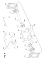
- Fig. 1 shows the basic structure of a hand tool 2 in the form of an optionally used as a drill or chisel hammer electro combi hammer.
- This has a housing 4, in which a drive motor 6 and driven by this electro-pneumatic impact mechanism 8 are housed.
- the impact mechanism 8 has a working means 10 in the form of a percussion piston, which is reciprocated during operation along a working axis A, by which a parallel first direction z is fixed.
- the working axis A in this case has a distance from a center of gravity S of the hand tool 2, which may be defined, for example, by the center of mass of the hand tool 2 in the middle position of the working means 10.
- a handle 14 is held, which extends substantially along a second direction y, which is perpendicular to the first direction z.
- This is connected to the housing 4 via a total of 16 designated Entkoppelungsan eleven.
- the decoupling arrangement 16 has a first spring-loaded bearing 18, which is arranged adjacent to the working axis A, and a second spring-loaded bearing 20 in the form of a rotary bearing, which is arranged at a distance from the working axis A and the first spring-loaded bearing 18 with respect to the second direction y ,
- the first spring-loaded bearing 18 has a first housing-side bearing device 22 with a first latch-shaped bearing element 24 which is enclosed by a first tubular bearing element 26 of a first grip-side bearing device 28.
- a first tubular bearing element 26 of a first grip-side bearing device 28 any other circumferential training can be selected.
- first latch-shaped bearing element 24 is supported along the first direction z toward a first side 30 via a first spring device 32, which is schematically represented here by a helical spring but can also be formed by other suitable spring means on the first tubular bearing element 26 , Towards a second side 34, which lies opposite the first side 30, the latch-shaped bearing element 24 rests against the tubular bearing element 26 via a stop 37 formed by a shaped part 36, in the unloaded state of the handheld power tool 2 shown here.
- first spring device 32 which is schematically represented here by a helical spring but can also be formed by other suitable spring means on the first tubular bearing element 26 .
- the second spring-loaded bearing 20 has a second housing-side bearing device 38 with a second latch-shaped bearing element 40 which is enclosed by a second tubular bearing element 42 of a second grip-side bearing device 44.
- the second latch-shaped bearing element 24 is supported in the radial direction circumferentially via a second spring device 46, which is shown schematically here by four coil springs but may also be formed by other suitable spring means, on the second tubular bearing element 42 from.
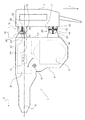
- Fig. 2 shows the hand tool 2 in operation.
- the handle 14 is acted upon by a contact pressure P1, P2, through which the hand tool 2 is pressed by a tool T against a material to be machined M.
- the handle 14 is in this case together with the two tubular bearing elements 26, 42 against a respective spring force F of the two spring means 32, 46 in the first direction z on the housing 4 moves.
- the abutment 37 of the molded part 36 held on the first latch-shaped bearing element 24 is spaced from the first tubular bearing element 26.
- the first latch-shaped bearing element 24 in the first direction z can oscillate freely with respect to the first tubular bearing element 26 under spring action of the first spring device 32.
- the latch-shaped bearing element 24, or the molded part 36 held thereon always has a distance in relation to the first tubular bearing element 26 on both sides for all forces acting in the intended operation.
- the spring action of the first spring device 32 in the second direction y is reduced to a minimum.
- the first spring-loaded bearing 18 has a lower spring stiffness along the second direction y than along the first direction z.
- the second latch-shaped bearing element 40 is still supported by the second spring device 46 to all sides radially relative to the second tubular bearing element 42.
- the spring constant or the spring constant of the second spring-loaded bearing 20 is higher than the spring constant of the first spring-loaded bearing 18.
- the construction as a pivot bearing also ensures a spring action in the direction of rotation D about the second latch-shaped bearing element 40 around.
- the second latch-shaped bearing element 40 in the first direction z, in the second direction y and also in the direction of rotation D freely under spring action of the second spring means 46 swing freely relative to the second tubular bearing element 42, wherein in the second direction y a disturbing interference by the Spring action of the first spring-loaded bearing 18 is omitted.
- the handle 14 can also be decoupled in all directions against torsional vibrations indicated by the arrow DS that arise on the housing 4 due to the distance of the center of gravity S from the working axis A.
- the first spring device 32 is essentially formed by an elastomer device made of foamed polyurethane.
- the spring device 32 is formed in several parts and has two substantially anvil-shaped elastomeric body 48 and two provided therebetween collar-shaped elastomer body 50, all of which are pushed onto the aligned parallel to a third direction x first locking element bearing 24, wherein the third direction x both against the the first direction z and with respect to the second direction y is perpendicular.
- the anvil-shaped elastomeric bodies 48 have in the first direction z on the first side 30 of the first latch-shaped bearing element 24 a biasing region 52 which extends further in the first direction z than a likewise respectively provided on the first side 30 support region 54 of the two collar-shaped Elastomer body 50.
- the two anvil-shaped elastomer body 48 each form a tapered stop region 49.
- This abutment region 49 has, in the first direction z, an extension which is only a fraction of the extent of the pretensioning region 52 in the first direction.
- two end-side elastomeric bodies 56 are provided, which are arranged in the installed state in each case between a side part 58 of the first housing-side bearing device 22 and a front-side flange 60 of the first tubular bearing element 26.
- a vibration reduction is also achieved in operation in the third direction x by at least partial decoupling of the first grip-side bearing device 28 from the first housing-side bearing device 22.
- the first spring-loaded bearing 18 by two fasteners 62, can be completely pre-assembled. These project through a respective receiving bore 64 of the side parts 58 and are fixed in a longitudinal bore 66 of the first latch-shaped bearing element 24, which are shown in FIG. 3.
- FIG. 5 shows the first spring-loaded bearing 18 in an unloaded starting position according to FIG. 1.
- the tapered stop 37 rests against a receiving groove 68 of the first tubular bearing element 26.
- the biasing region 52 is supported opposite to a bearing groove 70 of the first tubular bearing element 26.
- a certain fixation of the first latch-shaped bearing element 24 relative to the first tubular bearing element 26 is achieved in the unactuated state of the power tool 4 in the second direction y.
- the anvil-shaped elastomer body 48 together with the first tubular bearing element 26 in the second direction y, forms an intermediate space 47 on both sides.
- the stop 37 is removed from the receiving groove 68 in the first direction z.
- the gaps 47 remain, albeit recurring with reduced volume, permanently maintained during operation.
- a small spring effect can thus be generated only via the biasing region 52 pressed against the bearing groove 70.
- the biasing region 52 can also be compressed to such an extent that the first tubular bearing element 26 comes into contact with the support region 54 of the collar-shaped elastomer body 50 in the first direction z. In this case, we specifically increases the spring rigidity of the first spring device 32 in the first direction z.
- the second spring device 46 is essentially formed by an elastomer device made of foamed polyurethane.
- the second spring means 46 is formed in several parts and has two substantially star-shaped elastomer body 72 and two provided therebetween annular elastomer body 74, all of which are pushed onto the parallel to the third direction x aligned second latch-shaped bearing member 40.
- the star-shaped elastomer bodies 72 extend in the radial direction around the second latch-shaped bearing element 40 further than the two annular elastomer bodies 74.
- two end-face elastomeric bodies 76 are also provided here, which are each arranged in the installed state between a side part 78 of the second housing-side bearing means 38 and an end flange 80 of the second tubular bearing element 42.
- a vibration reduction is also achieved in operation in the third direction x by at least partial decoupling of the second grip-side bearing device 44 from the second housing-side bearing device 38.
- the second spring-loaded bearing 20 by two fasteners 82 can be completely pre-assembled. These project through a respective receiving bore 84 of the side parts 78 and are each fixed in a longitudinal bore 86 of the second latch-shaped bearing element 40, which are shown in FIG. 6.
- FIG. 8 shows the second spring-loaded bearing 20 in an unloaded starting position according to FIG. 1.
- the star-shaped elastomer bodies 72 have approximately the same spring stiffness in all radial directions around the second locking element 40, which is greater than the spring stiffness. which has the first spring-loaded bearing 18 with respect to the first tubular bearing element 26 spaced stop 37 in the second direction y.
- the star-shaped elastomer body 72 can also be compressed to the extent that the second tubular bearing element 42 comes into abutment in the relevant direction with the annular elastomer bodies 74, which act as a second support area. In this case, we selectively increases the spring stiffness of the second spring means 46 in this direction progressively.
- the second spring-loaded bearing 20 also in the direction of rotation D has a certain spring action, which decouples the handle 14 with respect to a rotational movement of the housing 4.
- each of the spring devices 32, 46 configured as an elastomer device
- a plurality of the elastomeric bodies 48, 50, 56; 72, 74, 76 also be formed in one piece.
- the second spring means 46 may alternatively be formed in addition to the illustrated embodiment by a leaf spring, but would have to allow the same degrees of freedom in all three directions x, y, z.
Abstract
Description
Die Erfindung betrifft ein Handwerkzeuggerät, insbesondere in Form eines wahlweise als Bohr- oder Meisselhammer verwendbaren Elektrokombihammers. Dieser weist ein Gehäuse auf, in dem ein Arbeitsmittel vorgesehen ist, das im Betrieb entlang einer zu einem Schwerpunkt des Handwerkzeuggerätes beabstandeten Arbeitsachse hin- und herbewegbar ist, die parallel zu einer ersten Richtung liegt. Beispielsweise kann das Arbeitsmittel durch einen Schlagkolben eines elektropneumatischen Schlagwerkes gebildet sein. Ferner weist das Handwerkzeuggerät einen Handgriff auf, der über eine Entkoppelungsanordnung an dem Gehäuse gehalten ist, um die Übertragung von Vibrationen vom Gehäuse zum Handgriff zu vermindern. Hierzu weist die Entkoppelungsanordnung ein erstes gefedertes Lager und ein zweites gefedertes Lager in Form eines Drehlagers auf, das in einer quer zur Arbeitsachse stehenden zweiten Richtung weiter von der Arbeitsachse beabstandet ist als das erste gefederte Lager.The invention relates to a hand tool, in particular in the form of an optionally usable as a drill or chisel hammer electro combi hammer. This has a housing in which a working means is provided, which is reciprocated during operation along a spaced apart from a center of gravity of the power tool working axis and which is parallel to a first direction. For example, the working fluid may be formed by a percussion piston of an electropneumatic striking mechanism. Further, the hand tool has a handle which is held on the housing via a decoupling arrangement to reduce the transmission of vibrations from the housing to the handle. For this purpose, the decoupling arrangement comprises a first spring-loaded bearing and a second spring-loaded bearing in the form of a rotary bearing, which is spaced further apart from the working axis in a second direction transverse to the working axis than the first spring-loaded bearing.
Bei derartigen Handwerkzeuggeräten werden im Betrieb durch den Abstand der Arbeitsachse zum Schwerpunkt Drehschwingungen am Gehäuse erzeugt. Durch die Verwendung eines gefederten Drehlagers, an dem eine gewisse Drehbewegung des Handgriffes gegenüber dem Gehäuse entgegen einer Federkraft ermöglicht wird, kann die Übertragung von Vibrationen, die aus diesen Drehschwingungen hervorgehen, auf den Handgriff vermindert werden. Hierdurch erreicht man neben einer Vibrationsminderung entlang der ersten Richtung auch eine deutliche Vibrationsminderung entlang der zweiten Richtung und dadurch einen hohen Komfort beim Halten des Gerätes.In such hand tool devices, torsional vibrations are generated on the housing during operation by the distance between the working axis and the center of gravity. By using a sprung rotary bearing, on which a certain rotational movement of the handle relative to the housing against a spring force is made possible, the transmission of vibrations arising from these torsional vibrations can be reduced to the handle. This achieves not only a reduction in vibration along the first direction but also a significant reduction in vibration along the second direction and thus a high level of comfort when holding the device.
Die Vibrationsminderung erfolgt dabei im Wesentlichen über die jeweilige weitgehend schwingungsentkoppelte Aufhängung, die einen grossen Teil der im Betrieb auftretenden Schwingungen vom Handgriff quasi isoliert, wobei je nach verwendeten Federmitteln auch eine mehr oder weniger grosse Dämpfungswirkung vorhanden ist. Nachfolgend wird dies unabhängig vom Anteil der Dämpfungswirkung vereinfacht als Entkoppelung bezeichnet.The vibration reduction is carried out essentially on the respective largely vibration-decoupled suspension, which virtually isolates a large part of the vibrations occurring during operation of the handle, depending on the spring means used also a more or less large damping effect is present. In the following, this is referred to as decoupling, irrespective of the proportion of the damping effect.
Aus der
Durch diese bekannte Ausbildung einer Entkoppelungsanordnung soll eine stabile Führung über den unteren Abfederungsbereich bei gleichzeitig hoher Dämpfungswirkung in Schlagrichtung über den oberen Abfederungsbereich erzielt werden.By this known training a decoupling a stable guidance over the lower Abfederungsbereich is to be achieved with simultaneous high damping effect in the direction of impact on the upper Abfederungsbereich.
Nachteilig an dem bekannten Handwerkzeuggerät ist jedoch, dass wegen der allseitigen Federwirkung an beiden Abfederungsbereichen keine ausreichende Entkoppelung des Handgriffes von den am Gehäuse auftretenden Drehschwingungen möglich ist. Vielmehr wird hinsichtlich der Drehschwingungen das Federverhalten beider Abfederungsbereiche überlagert. Infolge des relativ steifen unteren Abfederungsbereiches und der Überlagerung mit der auch in die zweite Richtung wirkenden Federwirkung des oberen Abfederungsbereiches verbleibt im Betrieb eine relativ hohe Vibration entlang der zweiten Richtung.A disadvantage of the known hand tool, however, is that due to the all-round spring action on both Abfederungsbereichen no adequate decoupling of the handle of the torsional vibrations occurring on the housing is possible. Rather, the spring behavior of both Abfederungsbereiche is superimposed with regard to the torsional vibrations. Due to the relatively stiff lower Abfederungsbereiches and the superposition with acting in the second direction spring action of the upper Abfederungsbereiches remains in operation, a relatively high vibration along the second direction.
Der vorliegenden Erfindung liegt die Aufgabe zugrunde, bei einem gattungsgemässen Handwerkzeuggerät die genannten Nachteile zu vermeiden und die infolge von Drehschwingungen auf den Handgriff übertragenen Vibrationen zu vermindern.The present invention has for its object to avoid the disadvantages mentioned in a generic hand tool and to reduce the vibrations transmitted to the handle as a result of torsional vibrations.
Erfindungsgemäss wird die Aufgabe dadurch gelöst, dass das erste gefederte Lager entlang der zweiten Richtung eine wesentlich geringere Federsteifigkeit aufweist als in der ersten Richtung. Auf diese Weise erfolgt die Entkoppelung des Handgriffes von den durch die Drehschwingungen um den Schwerpunkt am Gehäuse erzeugten Vibrationen entlang der zweiten Richtung massgeblich durch die Federwirkung am zweiten gefederten Lager. Dabei wird eine nachteilige Beeinflussung auf die Entkopplung der Drehschwingungen durch eine Federwirkung des ersten gefederten Lagers weitgehend vermieden. Hierdurch lässt sich eine besonders wirksame Entkoppelung des Handgriffes von den Drehschwingungen erzielen, die wiederum eine besonders komfortable Handhabung des Handwerkzeuggerätes im Betrieb ermöglicht.According to the invention, the object is achieved in that the first spring-loaded bearing along the second direction has a substantially lower spring stiffness than in the first direction. In this way, the decoupling of the handle from the vibrations generated by the torsional vibrations about the center of gravity on the housing takes place along the second direction substantially by the spring action on the second spring-loaded bearing. In this case, a disadvantageous influence on the decoupling of torsional vibrations by a spring action of the first spring-loaded bearing is largely avoided. This makes it possible to achieve a particularly effective decoupling of the handle from the torsional vibrations, which in turn allows a particularly comfortable handling of the power tool during operation.
In einer besonders bevorzugten Ausführungsform weist das erste gefederte Lager eine mit dem Gehäuse fest verbundene erste gehäuseseitige Lagereinrichtung und eine mit dem Handgriff fest verbundene erste griffseitige Lagereinrichtung auf. Zwischen diesen beiden ersten Lagereinrichtungen ist eine erste Federeinrichtung vorgesehen, mittels der diese voneinander federelastisch abstützbar sind und zwar im Wesentlichen in der ersten Richtung. Dagegen ist in der zweiten Richtung zwischen den ersten Lagereinrichtungen ein permanenter freier Zwischenraum vorgesehen, um eine Federwirkung in dieser Richtung zu minimieren. Hierdurch kann der Handgriff gegenüber den im Betrieb auftretenden Drehschwingungen am Gehäuse und den daraus resultierenden Vibrationen entlang der zweiten Richtung besonders gut entkoppelt werden, wobei die in der ersten Richtung aufzunehmenden hohen Vorschubkräfte durch eine hohe Federsteifigkeit aufgenommen werden können.In a particularly preferred embodiment, the first spring-loaded bearing has a first housing-side bearing device fixedly connected to the housing and a first grip-side bearing device fixedly connected to the handle. Between these two first bearing devices, a first spring device is provided, by means of which these are resiliently supportable from one another, specifically in the first direction. In contrast, in the second direction between the first storage facilities a permanent free space is provided to minimize a spring action in this direction. In this way, the handle can be particularly well decoupled from the torsional vibrations occurring in operation on the housing and the resulting vibrations along the second direction, wherein the high feed forces to be absorbed in the first direction can be absorbed by a high spring stiffness.
Vorteilhafterweise weist eine der ersten Lagereinrichtungen ein erstes riegelförmiges Lagerelement auf, das sich parallel zu einer dritten Richtung erstreckt, die senkrecht zu der ersten Richtung und der zweiten Richtung steht. Ferner weist die andere erste Lagereinrichtung ein das erste riegelförmige Lagerelement radial umschliessendes erstes rohrförmiges Lagerelement auf. Dabei stützt sich die erste Lagereinrichtung mit dem ersten riegelförmigen Lagerelement in der ersten Richtung zu einer ersten Seite hin unter Zwischenlage der ersten Federeinrichtung permanent am ersten rohrförmigen Lagerelement ab. Zu einer von der ersten Seite abgewandten zweiten Seite hin ist die erste Lagereinrichtung mit dem ersten riegelförmigen Lagerelement, in Abhängigkeit von einem am Handgriff aufgebrachten Anpressdruck, an dem ersten rohrförmigen Lagerelement anlegbar beziehungsweise von diesem beabstandbar. Hierdurch kann bei einem beispielsweise für den Betrieb des Schlagwerkes erforderlichen, am Handgriff aufgebrachten Anpressdruck eine gute Vibrationsisolierung in der ersten Richtung erzielt werden. Andererseits ist bei Aufbringung eines negativen Anpressdruckes, das heisst bei Aufbringung einer Zugkraft, am Handgriff ein besonders direkter Durchgriff vom Handgriff auf das restliche Gerät gewährleistet, um beispielsweise bei verklemmtem Werkzeug eine möglichst direkte Kraft an diesem aufbringen zu können, um es wieder zu lösen.Advantageously, one of the first bearing means comprises a first latch-shaped bearing member extending parallel to a third direction perpendicular to the first direction and the second direction. Furthermore, the other first bearing device has a first tubular bearing element radially enclosing the first tubular bearing element. In this case, the first bearing device is supported with the first latch-shaped bearing element in the first direction to a first side with the interposition of the first spring means permanently on the first tubular bearing element. At a second side facing away from the first side, the first bearing device with the first latch-shaped bearing element, depending on a pressure applied to the handle contact pressure, can be applied to the first tubular bearing element or spaced from this. As a result, a good vibration isolation in the first direction can be achieved in a required for example for the operation of the hammer mechanism, applied to the handle contact pressure. On the other hand, when applying a negative contact pressure, that is, when applying a tensile force on the handle a particularly direct penetration of the handle on the rest of the device ensures, for example, when jammed tool to apply the most direct force on this can to solve it again.
Bevorzugterweise weist die erste Federeinrichtung eine erste Elastomereinrichtung auf, die an der ersten Seite des ersten riegelförmigen Lagerelementes einen Vorspannbereich aufweist, der bezüglich der ersten Richtung eine mehrfach grössere Erstreckung aufweist als ein Anschlagbereich an der zweiten Seite des riegelförmigen Lagerelementes und die in der zweiten Richtung zu beiden Seiten des ersten riegelförmigen Lagerelementes einen permanenten Abstand zum ersten rohrförmigen Lagerelement aufweist. Die Elastomereinrichtung kann dabei beispielsweise aus einem geschäumten Kunststoff, wie insbesondere Polyurethan hergestellt sein. Hierdurch kann eine besonders günstige Federwirkung an dem Vorspannbereich erzielt werden, die eine gute Entkopplung und dadurch eine deutlich verminderte Vibrationsübertragung auf den Handgriff gewährleistet. Hierbei kann an dem aus geschäumtem Elastomer hergestellten Vorspannbereich eine mit zunehmendem Anpressdruck höhere Federsteifigkeit gewährleistet werden, die auch bei starker Beanspruchung eine gute Führung des Handwerkzeuggerätes ermöglicht. Der permanente Abstand der Elastomereinrichtung, der dabei hinsichtlich der zweiten Richtung zu beiden Seiten gegenüber dem ersten rohrförmigen Lagerelement eingehalten wird, gewährleistet dass in diese zweite Richtung keine Wesentliche Federwirkung auftritt. Lediglich durch den sich entlang der ersten Richtung erstreckenden Vorspannbereich wird dabei über dessen Querschnitt eine gewisse Federwirkung entlang der zweiten Richtung erzeugt, die jedoch gegenüber der Federsteifigkeit in der ersten Richtung deutlich kleiner ist.Preferably, the first spring means comprises a first elastomeric device having on the first side of the first latch-shaped bearing element a biasing region which has a multiple greater extension with respect to the first direction than a stopper area on the second side of the latch-shaped bearing element and in the second direction both sides of the first latch-shaped bearing element has a permanent distance from the first tubular bearing element. The Elastomer device can be made for example of a foamed plastic, such as polyurethane in particular. In this way, a particularly favorable spring action on the biasing region can be achieved, which ensures a good decoupling and thereby a significantly reduced vibration transmission to the handle. Here, on the biasing region made of foamed elastomer a higher spring stiffness can be ensured with increasing contact pressure, which enables good guidance of the hand tool device even under heavy load. The permanent distance of the elastomeric device, which is maintained with regard to the second direction on both sides relative to the first tubular bearing element, ensures that no essential spring action occurs in this second direction. Only by the biasing region extending along the first direction is a certain spring action along the second direction generated over the cross section thereof, which, however, is significantly smaller than the spring rigidity in the first direction.
Vorteilhafterweise weist die erste Elastomereinrichtung einen ersten Stützbereich auf, der entlang der ersten Richtung eine geringere Erstreckung als der Vorspannbereich aufweist. Hierdurch kann ab einer bestimmten Relativbewegung des Handgriffes gegenüber dem Gehäuse eine gezielte Progression der Federsteifigkeit der ersten Federeinrichtung erzielt werden. Durch diese kann, beispielsweise auch bei sehr hohen Anpressdrücken, ein schadhafter Kontakt zwischen dem Handgriff und dem Gehäuse verhindert werden.Advantageously, the first elastomeric device has a first support region which has a smaller extension along the first direction than the biasing region. In this way, a targeted progression of the spring stiffness of the first spring device can be achieved above a certain relative movement of the handle relative to the housing. By this, a defective contact between the handle and the housing can be prevented, for example, even at very high contact pressures.
Ferner weist das zweite gefederte Lager in der zweiten Richtung eine höhere Federsteifigkeit auf als das erste gefederte Lager, das heisst. Hierdurch erfolgt die Entkoppelung des Handgriffes von den durch die Drehschwingungen um den Schwerpunkt am Gehäuse erzeugten Vibrationen entlang der zweiten Richtung fast ausschliesslich durch die Federwirkung am zweiten gefederten Lager und ohne wesentliche Überlagerung durch Federwirkung des ersten gefederten Lagers.Furthermore, the second spring-loaded bearing in the second direction, a higher spring stiffness than the first spring-loaded bearing, that is. As a result, the decoupling of the handle of the vibrations generated by the torsional vibrations about the center of gravity on the housing along the second direction almost exclusively by the spring action on the second spring-loaded bearing and without substantial interference by spring action of the first spring-loaded bearing.
Dabei weist das zweite gefederte Lager vorteilhafterweise ein zweites riegelförmiges Lagerelement auf, das unter Zwischenlage einer zweiten Elastomereinrichtung von einem zweiten rohrförmigen Lagerelement radial umschlossen ist, wobei der zweite Elastomerkörper einen Bereich mit sternförmigem Querschnitt aufweist. Eine derartige Elastomereinrichtung ermöglicht eine besonders gute Einstellung einer vorbestimmten Federsteifigkeit, die gleichmässig in radialer Richtung um das zweite riegelförmige Lagerelement herum wirkt. Zudem kann auf diese Weise eine relativ weiche Federwirkung in Drehrichtung um das zweite riegelförmige Lagerelement herum erzeugt werden. Insgesamt wird hierdurch eine besonders gute Entkoppelung des Handgriffes gegenüber den infolge von Drehschwingungen erzeugten Vibrationen am Gehäuse erzielt.In this case, the second spring-loaded bearing advantageously has a second latch-shaped bearing element, which is radially enclosed by a second tubular bearing element with the interposition of a second elastomeric device, the second elastomeric body having a region with a star-shaped cross section. Such an elastomer device allows a particularly good setting of a predetermined spring stiffness, which acts evenly in the radial direction about the second locking element around the bar. In addition, in this way a relatively soft spring action in the direction of rotation can be generated around the second latch-shaped bearing element. All in all This results in a particularly good decoupling of the handle against the vibrations generated due to torsional vibration achieved on the housing.
Dabei ist es besonders günstig, wenn die zweite Elastomereinrichtung zwischen dem zweiten riegelförmigen Lagerelement und dem zweiten rohrförmigen Lagerelement einen zweiten Stützbereich aufweist, der umfänglich eine geringere radiale Erstreckung aufweist als der Bereich mit sternförmigem Querschnitt. Hierdurch kann an dem zweiten gefederten Lager ab einer bestimmten Relativbewegung des Handgriffes gegenüber dem Gehäuse in radialer Richtung des zweiten riegelförmigen Lagerelementes eine gezielte Progression der Federsteifigkeit der zweiten Elastomereinrichtung erzielt werden. Die zusätzliche Erhöhung der Federkennlinie durch den zweiten Stützbereich kann dabei durch dessen spezielle Ausbildung eingestellt werden, wie beispielsweise durch eine bestimmte Querschnittsform, eine veränderliche Dichte oder bestimmte Länge. In jedem Fall kann hierdurch bei sehr hohen Anpressdrücken oder beim Lösen eines verklemmten Werkzeuges auch am zweiten gefederten Lager ein schadhafter Kontakt zwischen dem Handgriff und dem Gehäuse verhindert werden.It is particularly advantageous if the second elastomeric device between the second latch-shaped bearing element and the second tubular bearing element has a second support region which has a smaller radial extent circumferentially than the region with a star-shaped cross-section. In this way, a targeted progression of the spring stiffness of the second elastomer device can be achieved at the second spring-loaded bearing from a certain relative movement of the handle relative to the housing in the radial direction of the second latch-shaped bearing element. The additional increase of the spring characteristic by the second support region can be adjusted by its special training, such as by a certain cross-sectional shape, a variable density or specific length. In any case, this can be prevented at very high contact pressures or when releasing a jammed tool on the second spring-loaded bearing a defective contact between the handle and the housing.
Die Erfindung wird nachstehend anhand eines Ausführungsbeispieles näher erläutert. Es zeigen:
- Fig. 1
- einen prinzipiellen Aufbau eines erfindungsgemässen Handwerkzeuggerätes,
- Fig. 2
- eine Ansicht des Handwerkzeuggerätes nach Fig. 1 bei Beaufschlagung durch einen Anpressdruck,
- Fig. 3
- eine perspektivische Explosionsansicht einer bevorzugten Ausführungsform eines ersten gefederten Lagers des Handwerkzeuggerätes,
- Fig. 4
- eine Ansicht des ersten gefederten Lagers nach Fig. 3 im vormontierten Zustand in einer ersten Richtung z,
- Fig. 5
- einen Schnitt durch das erste gefederte Lager in der Ebene V-V aus Fig. 4,
- Fig. 6
- eine perspektivische Explosionsansicht einer bevorzugten Ausführungsform eines zweiten gefederten Lagers des Handwerkzeuggerätes,
- Fig. 7
- eine Ansicht des zweiten gefederten Lagers nach Fig. 6 im vormontierten Zustand in einer ersten Richtung z und
- Fig. 8
- einen Schnitt durch das zweite gefederte Lager in der Ebene VIII-VIII aus Fig. 7
- Fig. 1
- a basic structure of a hand tool according to the invention,
- Fig. 2
- 1 is a view of the hand tool according to FIG. 1 when subjected to a contact pressure, FIG.
- Fig. 3
- an exploded perspective view of a preferred embodiment of a first spring-loaded bearing of the power tool,
- Fig. 4
- 3 a view of the first spring-loaded bearing in the preassembled state in a first direction z,
- Fig. 5
- a section through the first spring-loaded bearing in the plane VV of Fig. 4,
- Fig. 6
- an exploded perspective view of a preferred embodiment of a second spring-loaded bearing of the power tool,
- Fig. 7
- a view of the second spring-loaded bearing of FIG. 6 in the preassembled state in a first direction z and
- Fig. 8
- a section through the second spring-loaded bearing in the plane VIII-VIII of Fig. 7
Fig. 1 zeigt den prinzipiellen Aufbau eines Handwerkzeuggerätes 2 in Form eines wahlweise als Bohr- oder Meisselhammer verwendbaren Elektrokombihammers. Dieses weist ein Gehäuse 4 auf, in dem ein Antriebsmotor 6 und ein von diesem angetriebenes elektropneumatisches Schlagwerk 8 untergebracht sind. Das Schlagwerk 8 weist ein Arbeitsmittel 10 in Form eines Schlagkolbens auf, das im Betrieb entlang einer Arbeitsachse A hin- und herbewegt wird, durch die eine parallele erste Richtung z festgelegt ist. Die Arbeitsachse A weist dabei einen Abstand gegenüber einem Schwerpunkt S des Handwerkzeuggerätes 2 auf, der beispielsweise durch den Masseschwerpunkt des Handwerkzeuggerätes 2 bei Mittelstellung des Arbeitsmittels 10 definiert sein kann.Fig. 1 shows the basic structure of a
An einer Rückseite 12 des Gehäuses 4 ist ein Handgriff 14 gehalten, der sich im Wesentlichen entlang einer zweiten Richtung y erstreckt, die senkrecht zur ersten Richtung z steht. Dieser ist über eine insgesamt mit 16 bezeichnete Entkoppelungsanordnung mit dem Gehäuse 4 verbunden. Die Entkoppelungsanordnung 16 weist hierzu ein erstes gefedertes Lager 18, das benachbart zur Arbeitsachse A angeordnet ist, und ein zweites gefedertes Lager 20 in Form eines Drehlagers auf, das bezogen auf die zweite Richtung y beabstandet zur Arbeitsachse A und zum ersten gefederten Lager 18 angeordnet ist.On a
Das erste gefederte Lager 18 weist eine erste gehäuseseitige Lagereinrichtung 22 mit einem ersten riegelförmigen Lagerelement 24 auf, das von einem ersten rohrförmigen Lagerelement 26 einer ersten griffseitigen Lagereinrichtung 28 umschlossen ist. Alternativ kann statt der rohrförmigen Ausbildung der Lagereinrichtung 28 auch jede andere umlaufende Ausbildung gewählt werden. Dabei stützt sich das erste riegelförmige Lagerelement 24 entlang der ersten Richtung z zu einer ersten Seite 30 hin über eine erste Federeinrichtung 32, die hier schematisch durch eine Schraubenfeder dargestellt ist aber auch durch andere geeignete Federmittel gebildet sein kann, an dem ersten rohrförmigen Lagerelement 26 ab. Zu einer zweiten Seite 34 hin, die der ersten Seite 30 gegenüber liegt, liegt das riegelförmige Lagerelement 24, im hier dargestellten unbelasteten Zustand des Handwerkzeuggerätes 2, über einen durch ein Formteil 36 gebildeten Anschlag 37 an dem rohrförmigen Lagerelement 26 an.The first spring-loaded
Das zweite gefederte Lager 20 weist eine zweite gehäuseseitige Lagereinrichtung 38 mit einem zweiten riegelförmigen Lagerelement 40 auf, das von einem zweiten rohrförmigen Lagerelement 42 einer zweiten griffseitigen Lagereinrichtung 44 umschlossen ist. Dabei stützt sich das zweite riegelförmige Lagerelement 24 in radialer Richtung umlaufend über eine zweite Federeinrichtung 46, die hier schematisch durch vier Schraubenfedern dargestellt ist aber auch durch andere geeignete Federmittel gebildet sein kann, an dem zweiten rohrförmigen Lagerelement 42 ab.The second spring-loaded
Fig. 2 zeigt das Handwerkzeuggerät 2 im Betrieb. Dabei wird der Handgriff 14 mit einem Anpressdruck P1, P2 beaufschlagt, durch den das Handwerkzeuggerät 2 über ein Werkzeug T gegen ein zu bearbeitendes Material M gepresst wird. Der Handgriff 14 wird hierbei zusammen mit den beiden rohrförmigen Lagerelementen 26, 42 entgegen jeweils einer Federkraft F der beiden Federeinrichtungen 32, 46 in der ersten Richtung z auf das Gehäuse 4 zu bewegt.Fig. 2 shows the
Als Folge hiervon wird der Anschlag 37 des am ersten riegelförmigen Lagerelement 24 gehaltenen Formteils 36 von dem ersten rohrförmigen Lagerelement 26 beabstandet. Somit kann das erste riegelförmige Lagerelement 24 in der ersten Richtung z unter Federwirkung der ersten Federeinrichtung 32 frei gegenüber dem ersten rohrförmigen Lagerelement 26 schwingen.As a result, the
Entlang der zweiten Richtung y weist das riegelförmige Lagerelement 24, beziehungsweise das daran gehaltene Formteil 36, bei allen im vorgesehenen Betrieb auftretenden Krafteinflüssen zu beiden Seiten jeweils permanent einen Abstand gegenüber dem ersten rohrförmigen Lagerelement 26 auf. Durch die hierbei bezügliche der zweiten Richtung y auf beiden Seiten des ersten riegelförmigen Lagerelementes 24 entstehenden permanenten Zwischenräume 47 wird die Federwirkung der ersten Federeinrichtung 32 in der zweiten Richtung y auf ein Minimum reduziert. Dadurch weist das erste gefederte Lager 18 entlang der zweiten Richtung y eine geringere Federsteifigkeit auf als entlang der ersten Richtung z.Along the second direction y, the latch-shaped
Am zweiten gefederten Lager 20 ist das zweite riegelförmige Lagerelement 40 durch die zweite Federeinrichtung 46 nach wie vor zu allen Seiten radial gegenüber dem zweiten rohrförmigen Lagerelement 42 abgestützt. Somit ist in der zweiten Richtung y die Federkonstante beziehungsweise die Federkonstante des zweiten gefederten Lagers 20 höher als die Federkonstante des ersten gefederten Lagers 18.At the second spring-loaded
Zudem gewährleistet der Aufbau als Drehlager auch eine Federwirkung in Drehrichtung D um das zweite riegelförmige Lagerelement 40 herum. Somit kann das zweite riegelförmige Lagerelement 40 in der ersten Richtung z, in der zweiten Richtung y und auch in Drehrichtung D frei unter Federwirkung der zweiten Federeinrichtung 46 frei gegenüber dem zweiten rohrförmigen Lagerelement 42 schwingen, wobei in der zweiten Richtung y eine störende Überlagerung durch die Federwirkung des ersten gefederten Lagers 18 unterbleibt.In addition, the construction as a pivot bearing also ensures a spring action in the direction of rotation D about the second latch-shaped
Durch diesen prinzipiellen Aufbau der Entkopplungsanordnung 16 kann der Handgriff 14 auch gegenüber durch den Pfeil DS angedeuteten Drehschwingungen, die am Gehäuse 4 aufgrund des Abstandes des Schwerpunktes S von der Arbeitsachse A entstehen, wirksam in alle Richtungen entkoppelt werden.Due to this basic structure of the
Die Fig. 3 bis 5 zeigen eine besonders bevorzugte Ausführungsform des ersten gefederten Lagers 18. Dabei ist die erste Federeinrichtung 32 im Wesentlichen durch eine Elastomereinrichtung aus geschäumtem Polyurethan gebildet. Die Federeinrichtung 32 ist dabei mehrteilig ausgebildet und weist zwei im wesentlichen ambossförmige Elastomerkörper 48 und zwei dazwischen vorgesehene kragenförmige Elastomerkörper 50 auf, die allesamt auf das parallel zu einer dritten Richtung x ausgerichtete erste riegelförmige Lagerelement 24 aufgeschoben werden, wobei die dritte Richtung x sowohl gegenüber der ersten Richtung z als auch gegenüber der zweiten Richtung y senkrecht steht.3 to 5 show a particularly preferred embodiment of the first spring-loaded
Die ambossförmigen Elastomerkörper 48 weisen in der ersten Richtung z auf der ersten Seite 30 des ersten riegelförmigen Lagerelementes 24 einen Vorspannbereich 52 auf, der sich jeweils weiter in der ersten Richtung z erstreckt als ein ebenfalls jeweils auf der ersten Seite 30 vorgesehener Stützbereich 54 der beiden kragenförmigen Elastomerkörper 50. An der zweiten Seite 34 des ersten riegelförmigen Lagerelementes 24 bilden die beiden ambossförmigen Elastomerkörper 48 dagegen jeweils einen spitz zulaufenden Anschlagbereich 49 aus. Dieser Anschlagbereich 49 weist in der ersten Richtung z eine Erstreckung auf, die lediglich einen Bruchteil der Erstreckung des Vorspannbereiches 52 in der ersten Richtung beträgt. Auf diese Weise erhält man in Arbeitsrichtung des Handwerkzeuggerätes 2 eine relativ weiche Federung über den Vorspannbereich 52 während in entgegen gesetzter Richtung ein relativ harter Kontakt zwischen dem ersten riegelförmigen Lagerelement 24 und dem rohrförmigen Lagerelement 26 über den Anschlagbereich 49 herstellbar ist. Hierdurch erfolgt beim Ziehen am Handgriff 14 eine relativ direkte Kraftübertragung auf das Gehäuse 4 die vorteilhaft ist, um beispielsweise im Falle eines Verklemmens das Werkzeug T von dem zu bearbeitenden Material M trennen zu können.The anvil-shaped
Ferner sind zwei stirnseitige Elastomerkörper 56 vorgesehen, die im eingebauten Zustand jeweils zwischen einem Seitenteil 58 der ersten gehäuseseitigen Lagereinrichtung 22 und einem stirnseitigen Flansch 60 der ersten rohrförmigen Lagerelementes 26 angeordnet sind. Über diese stirnseitigen Elastomerkörper 56 wird im Betrieb auch in der dritten Richtung x eine Vibrationsminderung durch zumindest teilweise Entkoppelung der ersten griffseitigen Lagereinrichtung 28 von der ersten gehäuseseitigen Lagereinrichtung 22 erzielt.Furthermore, two end-side
Wie aus Fig. 4 zu entnehmen ist, kann das erste gefederte Lager 18 durch zwei Befestigungsmittel 62, komplett vormontiert werden. Diese durchragen jeweils eine Aufnahmebohrung 64 der Seitenteile 58 und sind in einer Längsbohrung 66 des ersten riegelförmigen Lagerelementes 24 festgelegt, die aus Fig. 3 zu entnehmen sind.As can be seen from Fig. 4, the first spring-loaded
Fig. 5 zeigt das erste gefederte Lager 18 in einer unbelasteten Ausgangsposition entsprechend Fig. 1. Hierbei liegt der spitz zulaufende Anschlag 37 an einer Aufnahmenut 68 des ersten rohrförmigen Lagerelementes 26 an. Zudem stützt sich der Vorspannbereich 52 gegenüber liegend an einer Lagernut 70 des ersten rohrförmigen Lagerelementes 26 ab. Hierdurch wird im unbetätigten Zustand des Handwerkzeuggerätes 4 auch in der zweiten Richtung y eine gewisse Fixierung des ersten riegelförmigen Lagerelementes 24 gegenüber dem ersten rohrförmigen Lagerelementes 26 erzielt. Im Übrigen bildet der ambossförmige Elastomerkörper 48 zusammen mit dem ersten rohrförmigen Lagerelement 26 in der zweiten Richtung y beidseitig jeweils einen Zwischenraum 47 aus.FIG. 5 shows the first spring-loaded
Durch Aufbringung des Anpressdruckes P1, P2 im Betrieb, entsprechend Fig. 2, am Handgriff 14 und damit an der ersten griffseitigen Lagereinrichtung 28 wird der Anschlag 37 in der ersten Richtung z von der Aufnahmenut 68 entfernt. Gleichzeitig bleiben die Zwischenräume 47, wenn auch wiederkehrend mit verkleinertem Volumen, während dem Betrieb permanent erhalten. Entlang der zweiten Richtung y kann somit lediglich noch über den gegen die Lagernut 70 gedrückten Vorspannbereich 52 eine geringe Federwirkung erzeugt werden.By applying the contact pressure P1, P2 during operation, according to FIG. 2, on the
Bei Aufbringung eines besonders hohen Anpressdruckes P1, P2 kann der Vorspannbereich 52 zudem soweit komprimiert werden, dass das erste rohrförmige Lagerelement 26 in der ersten Richtung z mit dem Stützbereich 54 des kragenförmigen Elastomerkörpers 50 in Anlage kommt. Dabei wir die Federsteifigkeit der ersten Federeinrichtung 32 in der ersten Richtung z gezielt erhöht.When applying a particularly high contact pressure P1, P2, the biasing
Die Fig. 6 bis 8 zeigen eine besonders bevorzugte Ausführungsform des zweiten gefederten Lagers 20, das als Drehlager ausgebildet ist. Dabei ist auch die zweite Federeinrichtung 46 im Wesentlichen durch eine Elastomereinrichtung aus geschäumtem Polyurethan gebildet. Die zweite Federeinrichtung 46 ist dabei mehrteilig ausgebildet und weist zwei im wesentlichen sternförmige Elastomerkörper 72 und zwei dazwischen vorgesehene ringförmige Elastomerkörper 74 auf, die allesamt auf das parallel zur dritten Richtung x ausgerichtete zweite riegelförmige Lagerelement 40 aufgeschoben werden.6 to 8 show a particularly preferred embodiment of the second spring-loaded
Die sternförmigen Elastomerkörper 72 erstrecken sich in radialer Richtung um das zweite riegelförmige Lagerelement 40 herum weiter als die beiden ringförmigen Elastomerkörper 74.The star-shaped
Ferner sind auch hier zwei stirnseitige Elastomerkörper 76 vorgesehen, die im eingebauten Zustand jeweils zwischen einem Seitenteil 78 der zweiten gehäuseseitigen Lagereinrichtung 38 und einem stirnseitigen Flansch 80 des zweiten rohrförmigen Lagerelementes 42 angeordnet sind. Über diese stirnseitigen Elastomerkörper 76 wird im Betrieb auch in der dritten Richtung x eine Vibrationsminderung durch zumindest teilweise Entkoppelung der zweiten griffseitigen Lagereinrichtung 44 von der zweiten gehäuseseitigen Lagereinrichtung 38 erzielt.Furthermore, two end-face
Wie aus Fig. 7 zu entnehmen ist, kann das zweite gefederte Lager 20 durch zwei Befestigungsmittel 82, komplett vormontiert werden. Diese durchragen jeweils eine Aufnahmebohrung 84 der Seitenteile 78 und sind jeweils in einer Längsbohrung 86 des zweiten riegelförmigen Lagerelementes 40 festgelegt, die aus Fig. 6 zu entnehmen sind.As can be seen from Fig. 7, the second spring-loaded
Fig. 8 zeigt das zweite gefederte Lager 20 in einer unbelasteten Ausgangsposition entsprechend Fig. 1. Im Betrieb weisen die sternförmigen Elastomerkörper 72 in alle radialen Richtungen um das zweite riegelförmige Lagerelement 40 herum in etwa eine gleiche Federsteifigkeit auf, die grösser ist als die Federsteifigkeit, die das erste gefederte Lager 18 bei gegenüber dem ersten rohrförmigen Lagerelement 26 beanstandetem Anschlag 37 in der zweiten Richtung y aufweist.8 shows the second spring-loaded
Bei Aufbringung einer besonders hohen Belastung in einer radialen Richtung kann der sternförmige Elastomerkörper 72 zudem soweit komprimiert werden, dass das zweite rohrförmige Lagerelement 42 in der betreffenden Richtung mit den ringförmigen Elastomerkörpern 74 in Anlage kommt, die als zweiter Stützbereich fungieren. Dabei wir die Federsteifigkeit der zweiten Federeinrichtung 46 in dieser Richtung gezielt progressiv erhöht.Upon application of a particularly high load in a radial direction, the star-shaped
Darüber hinaus weist das zweite gefederte Lager 20 auch in Drehrichtung D eine gewisse Federwirkung auf, die den Handgriff 14 hinsichtlich einer Drehbewegung des Gehäuses 4 entkoppelt.In addition, the second spring-loaded
Neben der jeweils dargestellten mehrteiligen Ausbildung der jeweils als Elastomereinrichtung ausgebildeten Federeinrichtungen 32, 46 können mehrere der Elastomerkörper 48, 50, 56; 72, 74, 76 auch einteilig ausgebildet sein. Darüber hinaus kann die zweite Federeinrichtung 46 neben der dargestellten Ausführungsform alternativ auch durch eine Blattfeder gebildet sein, die jedoch die gleichen Freiheitsgrade in alle drei Richtungen x, y, z ermöglichen müsste.In addition to the multi-part design of each of the
Claims (8)
mit einem Gehäuse (4), in dem ein Arbeitsmittel (10) vorgesehen ist, das im Betrieb entlang einer Arbeitsachse (A) hin- und herbewegbar ist, die parallel zu einer ersten Richtung (z) liegt,
und einem Handgriff (14), der über eine Entkoppeiungsanordnung (16) an dem Gehäuse (4) gehalten ist, die ein erstes gefedertes Lager (18) und ein zweites gefedertes Lager (20) aufweist, wobei das zweite gefederte Lager (20) bezüglich einer quer zur Arbeitsachse (A) stehenden zweiten Richtung (y) von der Arbeitsachse (A) weiter beabstandet ist als das erste gefederte Lager (18),
dadurch gekennzeichnet, dass das erste gefederte Lager (18) entlang der zweiten Richtung (y) eine geringere Federsteifigkeit aufweist als entlang der ersten Richtung (z).Hand tool (2)
a housing (4) in which a working means (10) is provided, which is reciprocable in operation along a working axis (A) which is parallel to a first direction (z),
and a handle (14) supported by a decoupling assembly (16) on the housing (4) having a first spring loaded bearing (18) and a second spring loaded bearing (20), the second spring loaded bearing (20) a transverse to the working axis (A) stationary second direction (y) of the working axis (A) is further spaced than the first spring-loaded bearing (18),
characterized in that the first spring-loaded bearing (18) along the second direction (y) has a lower spring stiffness than along the first direction (z).
Applications Claiming Priority (1)
| Application Number | Priority Date | Filing Date | Title |
|---|---|---|---|
| DE102006000375A DE102006000375A1 (en) | 2006-07-27 | 2006-07-27 | Hand tool with decoupling arrangement |
Publications (2)
| Publication Number | Publication Date |
|---|---|
| EP1882559A1 true EP1882559A1 (en) | 2008-01-30 |
| EP1882559B1 EP1882559B1 (en) | 2014-06-04 |
Family
ID=38662695
Family Applications (1)
| Application Number | Title | Priority Date | Filing Date |
|---|---|---|---|
| EP07112663.5A Active EP1882559B1 (en) | 2006-07-27 | 2007-07-18 | Hand tool with decoupling arrangement |
Country Status (4)
| Country | Link |
|---|---|
| US (1) | US7610967B2 (en) |
| EP (1) | EP1882559B1 (en) |
| JP (1) | JP5124195B2 (en) |
| DE (1) | DE102006000375A1 (en) |
Cited By (4)
| Publication number | Priority date | Publication date | Assignee | Title |
|---|---|---|---|---|
| EP2082845A2 (en) | 2008-01-24 | 2009-07-29 | Black & Decker, Inc. | Mounting assembly for handle for power tool |
| EP2103392A1 (en) * | 2008-03-18 | 2009-09-23 | Black & Decker, Inc. | Hammer |
| EP3626399A1 (en) | 2018-09-20 | 2020-03-25 | Hilti Aktiengesellschaft | Handheld machine tool and method for operating the same |
| EP3943251A1 (en) * | 2020-07-22 | 2022-01-26 | Hilti Aktiengesellschaft | Shock absorber device for a battery |
Families Citing this family (29)
| Publication number | Priority date | Publication date | Assignee | Title |
|---|---|---|---|---|
| DE102006029630A1 (en) * | 2006-06-28 | 2008-01-03 | Robert Bosch Gmbh | Hand tool |
| DE102006051924A1 (en) * | 2006-11-03 | 2008-05-15 | Robert Bosch Gmbh | Hand tool with a vibration-damped, provided with a switch handle |
| DE102006052807A1 (en) * | 2006-11-09 | 2008-05-15 | Robert Bosch Gmbh | Hand tool with a vibration-damped strap handle |
| DE102007012312A1 (en) * | 2007-03-14 | 2008-09-18 | Robert Bosch Gmbh | handle |
| US8100745B2 (en) * | 2007-03-16 | 2012-01-24 | Black & Decker Inc. | Low vibration sander with a flexible top handle |
| DE102007055843A1 (en) * | 2007-12-17 | 2009-06-25 | Hilti Aktiengesellschaft | Hand tool with vibration compensator |
| GB0804963D0 (en) * | 2008-03-18 | 2008-04-16 | Black & Decker Inc | Hammer |
| US7938196B2 (en) * | 2009-04-17 | 2011-05-10 | Hilti Aktiengesellschaft | Hand-held power tool with vibration-compensating mass |
| DE102009002589A1 (en) * | 2009-04-23 | 2010-10-28 | Hilti Aktiengesellschaft | Hand tool |
| JP5436071B2 (en) * | 2009-07-02 | 2014-03-05 | 株式会社マキタ | Work tools |
| JP5502458B2 (en) | 2009-12-25 | 2014-05-28 | 株式会社マキタ | Impact tool |
| JP5496812B2 (en) * | 2010-08-03 | 2014-05-21 | 株式会社マキタ | Work tools |
| US20120048580A1 (en) * | 2010-09-01 | 2012-03-01 | Hilti Aktiengesellschaft | Power tool |
| DE102010040173A1 (en) * | 2010-09-02 | 2012-03-08 | Hilti Aktiengesellschaft | Hand tool |
| US8966773B2 (en) | 2012-07-06 | 2015-03-03 | Techtronic Power Tools Technology Limited | Power tool including an anti-vibration handle |
| KR101389960B1 (en) * | 2012-09-12 | 2014-04-29 | 한양대학교 에리카산학협력단 | Vibration suppression device for machine tool |
| JP6096593B2 (en) * | 2013-05-29 | 2017-03-15 | 株式会社マキタ | Reciprocating work tool |
| EP2898993B1 (en) | 2014-01-23 | 2019-01-30 | Black & Decker Inc. | Power tool |
| EP2898992B1 (en) * | 2014-01-23 | 2016-05-04 | Black & Decker Inc. | Power tool with rear handle, method of manufacturing a part of a handle assembly for a power tool and method of disassembling a part of a handle assembly for a power tool |
| EP2898991B1 (en) * | 2014-01-23 | 2018-12-26 | Black & Decker Inc. | Rear handle |
| EP2898994A1 (en) | 2014-01-23 | 2015-07-29 | Black & Decker Inc. | Power tool with rear handle |
| JP6620434B2 (en) * | 2015-06-12 | 2019-12-18 | マックス株式会社 | Impact tool |
| EP3501750A1 (en) * | 2017-12-19 | 2019-06-26 | Hilti Aktiengesellschaft | Vibration-dampened hand-held machine tool |
| CN110549303A (en) * | 2018-05-31 | 2019-12-10 | 苏州宝时得电动工具有限公司 | Impact tool |
| CN108747937B (en) * | 2018-06-12 | 2020-02-28 | 国网山东省电力公司烟台供电公司 | Insulated electric wrench |
| JP2022119301A (en) * | 2021-02-04 | 2022-08-17 | 株式会社マキタ | impact tool |
| JP2022128006A (en) * | 2021-02-22 | 2022-09-01 | 株式会社マキタ | impact tool |
| US11919138B2 (en) * | 2021-10-19 | 2024-03-05 | Makita Corporation | Impact tool |
| DE102022118307A1 (en) | 2022-07-21 | 2024-02-01 | Andreas Stihl Ag & Co. Kg | Hand-held work tool |
Citations (4)
| Publication number | Priority date | Publication date | Assignee | Title |
|---|---|---|---|---|
| DE3312195A1 (en) | 1983-04-02 | 1984-10-11 | Wacker-Werke Gmbh & Co Kg, 8077 Reichertshofen | HANDMADE HAMMER AND DRILL |
| EP0165341B1 (en) * | 1984-03-23 | 1988-05-25 | Metabowerke GmbH & Co. | Single space damper and its use in a hand tool |
| DE10335720A1 (en) * | 2003-08-05 | 2005-02-24 | Andreas Stihl Ag & Co. Kg | Anti-vibration element |
| EP1800805A2 (en) | 2005-12-23 | 2007-06-27 | HILTI Aktiengesellschaft | Handle of a hand held tool |
Family Cites Families (14)
| Publication number | Priority date | Publication date | Assignee | Title |
|---|---|---|---|---|
| US3972119A (en) * | 1975-08-25 | 1976-08-03 | Mcculloch Corporation | Chain saw with a bifurcated diaphragm means providing a coaxial vibration-isolating unit |
| JPS5834271B2 (en) * | 1980-07-18 | 1983-07-26 | 日立工機株式会社 | Vibrating tool handle vibration isolator |
| JP2931025B2 (en) * | 1989-03-18 | 1999-08-09 | アンドレアス シュティール | Motor-driven hand-held power tool with grips joined by anti-vibration elements |
| JPH08126975A (en) * | 1994-10-28 | 1996-05-21 | Hitachi Koki Co Ltd | Vibration control handle of electric hammer |
| US5697456A (en) * | 1995-04-10 | 1997-12-16 | Milwaukee Electric Tool Corp. | Power tool with vibration isolated handle |
| DE19530712B4 (en) * | 1995-08-21 | 2006-12-28 | Fa. Andreas Stihl | Anti-vibration element for arrangement between a motor unit and a handle unit in a hand-held implement |
| DE19646622B4 (en) * | 1996-11-12 | 2004-07-01 | Wacker Construction Equipment Ag | Tool that can be carried in one movement |
| US6648535B2 (en) * | 2001-02-27 | 2003-11-18 | Daniel A. Ferrara, Jr. | Cushioning element |
| DE10136015A1 (en) * | 2001-07-24 | 2003-02-13 | Bosch Gmbh Robert | Hand-held machine tool has vibration-dampened hand grip of two legs with levers hinged top hand grip legs and machine housing |
| DE10145464C2 (en) * | 2001-09-14 | 2003-08-28 | Wacker Construction Equipment | Drill and / or impact hammer with idle control depending on the contact pressure |
| GB2407791A (en) * | 2003-11-04 | 2005-05-11 | Black & Decker Inc | Vibration reduction apparatus for a power tool |
| DE102004019776A1 (en) * | 2004-04-23 | 2005-11-17 | Robert Bosch Gmbh | Hand tool, in particular drill and / or percussion hammer |
| US7252156B2 (en) * | 2005-03-31 | 2007-08-07 | Makita Corporation | Vibration isolation handle |
| DE102005038088A1 (en) * | 2005-08-11 | 2007-02-15 | Hilti Ag | Connecting arrangement between main housing and handle housing |
-
2006
- 2006-07-27 DE DE102006000375A patent/DE102006000375A1/en not_active Withdrawn
-
2007
- 2007-07-18 EP EP07112663.5A patent/EP1882559B1/en active Active
- 2007-07-25 US US11/881,257 patent/US7610967B2/en active Active
- 2007-07-26 JP JP2007195115A patent/JP5124195B2/en not_active Expired - Fee Related
Patent Citations (4)
| Publication number | Priority date | Publication date | Assignee | Title |
|---|---|---|---|---|
| DE3312195A1 (en) | 1983-04-02 | 1984-10-11 | Wacker-Werke Gmbh & Co Kg, 8077 Reichertshofen | HANDMADE HAMMER AND DRILL |
| EP0165341B1 (en) * | 1984-03-23 | 1988-05-25 | Metabowerke GmbH & Co. | Single space damper and its use in a hand tool |
| DE10335720A1 (en) * | 2003-08-05 | 2005-02-24 | Andreas Stihl Ag & Co. Kg | Anti-vibration element |
| EP1800805A2 (en) | 2005-12-23 | 2007-06-27 | HILTI Aktiengesellschaft | Handle of a hand held tool |
Cited By (9)
| Publication number | Priority date | Publication date | Assignee | Title |
|---|---|---|---|---|
| EP2082845A2 (en) | 2008-01-24 | 2009-07-29 | Black & Decker, Inc. | Mounting assembly for handle for power tool |
| EP2082845A3 (en) * | 2008-01-24 | 2011-09-14 | Black & Decker, Inc. | Mounting assembly for handle for power tool |
| US8708059B2 (en) | 2008-01-24 | 2014-04-29 | Black & Decker Inc. | Mounting assembly for handle for power tool |
| EP2103392A1 (en) * | 2008-03-18 | 2009-09-23 | Black & Decker, Inc. | Hammer |
| US7886838B2 (en) | 2008-03-18 | 2011-02-15 | Black & Decker Inc. | Hammer |
| EP3626399A1 (en) | 2018-09-20 | 2020-03-25 | Hilti Aktiengesellschaft | Handheld machine tool and method for operating the same |
| WO2020058031A1 (en) | 2018-09-20 | 2020-03-26 | Hilti Aktiengesellschaft | Portable power tool and method for operating a portable power tool |
| EP3943251A1 (en) * | 2020-07-22 | 2022-01-26 | Hilti Aktiengesellschaft | Shock absorber device for a battery |
| WO2022017846A1 (en) * | 2020-07-22 | 2022-01-27 | Hilti Aktiengesellschaft | Impact damping unit for an accumulator |
Also Published As
| Publication number | Publication date |
|---|---|
| US20080047724A1 (en) | 2008-02-28 |
| US7610967B2 (en) | 2009-11-03 |
| EP1882559B1 (en) | 2014-06-04 |
| JP2008030192A (en) | 2008-02-14 |
| JP5124195B2 (en) | 2013-01-23 |
| DE102006000375A1 (en) | 2008-01-31 |
Similar Documents
| Publication | Publication Date | Title |
|---|---|---|
| EP1882559B1 (en) | Hand tool with decoupling arrangement | |
| EP1882558B1 (en) | Hand tool with decoupling arrangement | |
| EP0949988B1 (en) | Percussion drill and/or jack hammer with handle spring-buffered against the hammer housing | |
| EP2425937B1 (en) | Hand-held machine tool | |
| EP1817139B1 (en) | Manual machine tool handle device comprising a vibration-shielding unit | |
| EP2119537A1 (en) | Electric hand tool | |
| EP2253430B1 (en) | Electric tool machine, in particular handheld hammer drill | |
| EP2512750B1 (en) | Hand-power tool with an oscillation-damping device | |
| EP2906375A1 (en) | Vibrating hammer having rebound damping | |
| DE102007012312A1 (en) | handle | |
| EP1691954B1 (en) | Percussion hammer and/or drill hammer comprising a handle which can be guided in a linear manner | |
| EP1674210B1 (en) | Tool with main handle mechanically decoupled | |
| EP1221359B1 (en) | Vibration isolating device | |
| WO2021094213A1 (en) | Striking mechanism assembly | |
| DE10215237A1 (en) | Hand-held motor-driven work tool | |
| DE10236135A1 (en) | Portable electric hand tool e.g. drill and chisel hammer, provided with handgrip which is spring-loaded for movement relative to tool housing for providing vibration damping | |
| DE10361294B4 (en) | Anti-vibration element | |
| DE102009029626B4 (en) | Hand tool | |
| WO2013131677A1 (en) | Hand-machine tool device | |
| DE102008000937A1 (en) | Electric hand tool with flatwave shaft spring | |
| EP3274132B1 (en) | Hand-held power tool | |
| EP0312831B1 (en) | Vibration isolator for a pneumatic chiselling hammer | |
| EP1950450A1 (en) | Dampening element | |
| DE102022112966A1 (en) | Vibration absorber with double mass | |
| WO2012045504A1 (en) | Multidimensional vibration damper |
Legal Events
| Date | Code | Title | Description |
|---|---|---|---|
| PUAI | Public reference made under article 153(3) epc to a published international application that has entered the european phase |
Free format text: ORIGINAL CODE: 0009012 |
|
| AK | Designated contracting states |
Kind code of ref document: A1 Designated state(s): AT BE BG CH CY CZ DE DK EE ES FI FR GB GR HU IE IS IT LI LT LU LV MC MT NL PL PT RO SE SI SK TR |
|
| AX | Request for extension of the european patent |
Extension state: AL BA HR MK YU |
|
| 17P | Request for examination filed |
Effective date: 20080730 |
|
| AKX | Designation fees paid |
Designated state(s): CH DE FR GB LI SE |
|
| 17Q | First examination report despatched |
Effective date: 20081020 |
|
| RIC1 | Information provided on ipc code assigned before grant |
Ipc: B25D 17/04 20060101AFI20140130BHEP Ipc: B25F 5/00 20060101ALI20140130BHEP |
|
| GRAP | Despatch of communication of intention to grant a patent |
Free format text: ORIGINAL CODE: EPIDOSNIGR1 |
|
| INTG | Intention to grant announced |
Effective date: 20140320 |
|
| GRAS | Grant fee paid |
Free format text: ORIGINAL CODE: EPIDOSNIGR3 |
|
| GRAA | (expected) grant |
Free format text: ORIGINAL CODE: 0009210 |
|
| AK | Designated contracting states |
Kind code of ref document: B1 Designated state(s): CH DE FR GB LI SE |
|
| REG | Reference to a national code |
Ref country code: GB Ref legal event code: FG4D Free format text: NOT ENGLISH |
|
| REG | Reference to a national code |
Ref country code: CH Ref legal event code: EP |
|
| REG | Reference to a national code |
Ref country code: DE Ref legal event code: R096 Ref document number: 502007013162 Country of ref document: DE Effective date: 20140710 |
|
| REG | Reference to a national code |
Ref country code: SE Ref legal event code: TRGR |
|
| REG | Reference to a national code |
Ref country code: DE Ref legal event code: R097 Ref document number: 502007013162 Country of ref document: DE |
|
| PLBE | No opposition filed within time limit |
Free format text: ORIGINAL CODE: 0009261 |
|
| STAA | Information on the status of an ep patent application or granted ep patent |
Free format text: STATUS: NO OPPOSITION FILED WITHIN TIME LIMIT |
|
| 26N | No opposition filed |
Effective date: 20150305 |
|
| REG | Reference to a national code |
Ref country code: DE Ref legal event code: R097 Ref document number: 502007013162 Country of ref document: DE Effective date: 20150305 |
|
| REG | Reference to a national code |
Ref country code: FR Ref legal event code: PLFP Year of fee payment: 10 |
|
| REG | Reference to a national code |
Ref country code: FR Ref legal event code: PLFP Year of fee payment: 11 |
|
| REG | Reference to a national code |
Ref country code: FR Ref legal event code: PLFP Year of fee payment: 12 |
|
| PGFP | Annual fee paid to national office [announced via postgrant information from national office to epo] |
Ref country code: FR Payment date: 20190719 Year of fee payment: 13 |
|
| PGFP | Annual fee paid to national office [announced via postgrant information from national office to epo] |
Ref country code: CH Payment date: 20190719 Year of fee payment: 13 |
|
| REG | Reference to a national code |
Ref country code: CH Ref legal event code: PL |
|
| PG25 | Lapsed in a contracting state [announced via postgrant information from national office to epo] |
Ref country code: CH Free format text: LAPSE BECAUSE OF NON-PAYMENT OF DUE FEES Effective date: 20200731 Ref country code: LI Free format text: LAPSE BECAUSE OF NON-PAYMENT OF DUE FEES Effective date: 20200731 Ref country code: FR Free format text: LAPSE BECAUSE OF NON-PAYMENT OF DUE FEES Effective date: 20200731 |
|
| P01 | Opt-out of the competence of the unified patent court (upc) registered |
Effective date: 20230830 |
|
| PGFP | Annual fee paid to national office [announced via postgrant information from national office to epo] |
Ref country code: GB Payment date: 20230720 Year of fee payment: 17 |
|
| PGFP | Annual fee paid to national office [announced via postgrant information from national office to epo] |
Ref country code: SE Payment date: 20230719 Year of fee payment: 17 Ref country code: DE Payment date: 20230719 Year of fee payment: 17 |