EP1882513B1 - Manifold adaptor plate for filtration apparatus - Google Patents
Manifold adaptor plate for filtration apparatus Download PDFInfo
- Publication number
- EP1882513B1 EP1882513B1 EP07112936A EP07112936A EP1882513B1 EP 1882513 B1 EP1882513 B1 EP 1882513B1 EP 07112936 A EP07112936 A EP 07112936A EP 07112936 A EP07112936 A EP 07112936A EP 1882513 B1 EP1882513 B1 EP 1882513B1
- Authority
- EP
- European Patent Office
- Prior art keywords
- plate
- holes
- manifold
- elastomeric
- rigid plate
- Prior art date
- Legal status (The legal status is an assumption and is not a legal conclusion. Google has not performed a legal analysis and makes no representation as to the accuracy of the status listed.)
- Active
Links
Images





Classifications
-
- B—PERFORMING OPERATIONS; TRANSPORTING
- B01—PHYSICAL OR CHEMICAL PROCESSES OR APPARATUS IN GENERAL
- B01D—SEPARATION
- B01D63/00—Apparatus in general for separation processes using semi-permeable membranes
- B01D63/08—Flat membrane modules
- B01D63/082—Flat membrane modules comprising a stack of flat membranes
- B01D63/0822—Plate-and-frame devices
-
- B—PERFORMING OPERATIONS; TRANSPORTING
- B01—PHYSICAL OR CHEMICAL PROCESSES OR APPARATUS IN GENERAL
- B01D—SEPARATION
- B01D65/00—Accessories or auxiliary operations, in general, for separation processes or apparatus using semi-permeable membranes
- B01D65/003—Membrane bonding or sealing
-
- B—PERFORMING OPERATIONS; TRANSPORTING
- B01—PHYSICAL OR CHEMICAL PROCESSES OR APPARATUS IN GENERAL
- B01D—SEPARATION
- B01D2313/00—Details relating to membrane modules or apparatus
- B01D2313/04—Specific sealing means
- B01D2313/041—Gaskets or O-rings
Definitions
- the present invention relates to a manifold adaptor plate that functions as a gasket utilized to separate filtrate from feed and retentate in a tangential flow filtration apparatus. More particularly, this invention relates to such a manifold adaptor plate of unitary construction having a plurality of layers including one or two sealing layers and an intermediate rigid support layer.
- liquids Prior to the present invention, liquids, primarily aqueous liquids, have been filtered by tangential flow modules wherein a plurality of filters are stacked between two manifolds, one at the bottom of the stack and one at the top of the stack.
- the filtration module stack comprises a collection of one or more filtration modules and associated intermodule gaskets.
- the filters are separated by appropriate screens and liquid-impervious layers to permit liquid flow as well as filtrate and retentate flow into and from the stack.
- flow holes are provided through the layers within the stack. The holes are sealed appropriately with a separate sheet of gasketing material to prevent admixture of filtrate with incoming liquid feed or retentate.
- the manifolds in each segment are designed so that filtrate is removed from the second manifold.
- This manifold arrangement necessitates fittings to both manifolds in order to supply and remove liquid to and from manifolds in order to supply and remove liquid to and from the stack. This can be undesirable since additional manipulative steps for removing and connecting the fittings are required when it is desirable to replace the filtration elements forming the stack.
- a separate sheet of gasket material is positioned between the one or two manifolds and the stack of filters to assure the desired liquid flow.
- the gasket sheet is used with manifold adaptor plate consists of a metal plate.
- the elastomeric gasket sheet such as silicone, can be placed against each surface of the metal plate to provide desired sealing.
- the metal plate and elastomeric gasket sheets are provided with liquid flow paths to assure the desired liquid flow to, within and from the tangential flow module.
- a manifold adaptor plate having a separate elastomeric sheet layer is undesirable, since, due to its flexibility, it is difficult to properly align the liquid flow paths through the elastomeric layer with the liquid inlets and liquid outlets of the manifold. In some instances it is possible to deform the gasket sheet during application in such a manner to allow for the improper mixing of fluids. In addition, the elastomeric layer tends to stick to the manifold causing wrinkling that adversely affects uniform and complete contact with the manifold surface. This condition can lead to external leaks as well as imperfect alignment of liquid flow paths that can cause cross contamination of flowing liquids.
- the separate sheet is generally formed of silicone which has relatively high extractables that can be adding to the fluid that passes through it. These extractables need to either be removed from the fluid before use or to be tested to ensure they don't contaminate or otherwise cause an adverse reaction in the final product, particularly when it is a drug or therapeutic protein.
- the gasket sheet being a relatively weak and unsupported structure formed of relatively low durometer silicone or rubber, it can tear during handling and storage rendering it useless and they can distort enough to cause an external leak as well.
- US2003/192783A1 discloses an end plate of an electro-deionization apparatus which is formed from a rigid end plate formed of structural material such as metal and polymeric materials, which is completely or partially overmolded with resilient material to form a combination end plate.
- a rigid end plate formed of structural material such as metal and polymeric materials, which is completely or partially overmolded with resilient material to form a combination end plate.
- the interior peripheral wall of a passageway extending from the end plate through an integral connector fitting is covered by the resilient material which further extends beyond an end of the connector fitting and outwardly against an end face forming a lip that acts like a gasket when the fitting is mated with an exterior connection.
- the present invention provides a manifold adaptor plate as defined in claim 1 or in claim 2. Preferred embodiments are defined in the dependent claims.
- the present invention provides a manifold adaptor plate comprising a rigid plate layer, a polymeric sheet layer and one or two elastomeric layers. Each layer is provided with holes which permit passage therethrough of liquid feed, filtrate and retentate without mixing of filtrate with either retentate or feed.
- a manifold adaptor plate comprising a rigid plate layer, a polymeric sheet layer and one or two elastomeric layers.
- Each layer is provided with holes which permit passage therethrough of liquid feed, filtrate and retentate without mixing of filtrate with either retentate or feed.
- it is molded onto a first surface of the rigid plate layer and through all of the holes of each layer so that it is bound to a portion of the area on the polymeric sheet surrounding the holes through the polymeric sheet that is contact with the opposite or second surface of the rigid plate.
- the elastomeric layer By effecting binding of the polymeric sheet to the elastomeric layer, the elastomeric layer is provided with a rigid support by the rigid plate layer and the elastomeric layer does not move relative to the rigid plate layer. By providing rigid support to the elastomeric layer, it can be properly and easily positioned in contact with a manifold to effect desired sealing.
- two elastomeric layers are utilized, one in contact with a first surface of the rigid plate layer and the second in contact with the polymeric sheet which is in contact with the second opposite surface of the rigid plate.
- the elastomeric layers are bound to each other through holes formed in the rigid plate layer and the polymeric sheet.
- This embodiment provides two sealing layers which can be utilized to seal a manifold or a filtration module to prevent admixture of filtrate with either feed or retentate.
- the plate can be used between two devices.
- the elastomeric sheets are sufficiently flexible that they can effect sealing of a manifold or filtration module in contact with the elastomeric sheet to prevent admixture of filtrate with feed or retentate flowing within the manifold of filtration module.
- they are made of thermoplastic elastomers which have low levels of extractables.
- a manifold apparatus 1 within which the manifold adaptor plate of this invention can be incorporated includes a first set of manifold segments 2 and 4, connected together; a feed manifold segment 6 and a second set of manifold segments 8 and 10 connected together and mounted on manifold frame 12.
- the first set of manifold segments 2 and 4 is provided with a filtrate outlet 14 and a retentate vent 16.
- the second set of manifold segments 8 and 10 is provided with a filtrate outlet 18 and a retentate drain 20.
- the retentate drain 20 and retentate vent 16 are capped during filtration.
- the retentate vent 16 permits filling the retentate flow path with liquid and the retentate drain permits draining the apparatus of retentate upon completion of the filtration.
- the feed segment 6 is provided with a feed inlet 22 and a retentate outlet 25.
- the feed inlet can have a diameter larger than that of internal feed conduits within the manifold segments since the incoming feed is split into the first set of manifold segments 2 and 4 and the second set of segments 8 and 10.
- a plurality of filtration modules 24 are secured to manifold segments 2, 4, 8 and 10 by means of plates 26 and a plurality of compression assemblies 28 such as bolts. Alternatively, threaded rods having nuts on their ends can be utilized rather than bolts.
- the manifold adaptor plate 11 ( Fig. 6 ) of this invention is positioned between the filtration modules 24 and the manifold segments 2, 4, 8 and 10.
- manifold adaptor plate 11 of this invention consists of polymeric sheet 13, a rigid plate 19 that is formed of a thermosetting resin, reinforced composites such as graphite or carbon composites or a metal such as stainless steel, Hastelloy metal or aluminum and an elastomeric layer 17.
- the rigid plate 19 has two major surfaces, 7A and 7B, respectively.
- the polymeric sheet is arranged to be in contact with one major surface of the rigid plate, in the instance of Figs 2 and 3 with the first major surface 7A while the elastomeric layer 17 is arranged to be in contact with the other major surface that is opposite the first surface, in the instance of Figs 2 and 3 with the second major surface 7B.
- Each layer 13, 17 and 19 is provided with holes to effect desired liquid flow through the plate 11.
- the holes of each layer 13, 17, 19 are in line and in register with each other to ensure proper flow and sealing in the fluid pathway and to ensure proper bonding of the elastomeric layer to the polymeric layer.
- Each layer 13, 17 and 19 have one edge with alternating holes 50 for filtrate with holes 56 for retentate. The opposing edge is provided with holes 48 for feed which alternate with holes 50 for filtrate.
- Fig. 3 which is a close up of the assembled plate 11 shown through one hole, in this case hole 50, the elastomeric layer 17 extends through each hole 48, 50 and 56 to form protrusions 15 that extend over and bind to polymeric sheet 13.
- the manifold adaptor plate 11 is provided with four indentations 21 which permit the plate 11 to be hung on bolts 28 ( Fig. 1 ), however this is not required and other means can used instead.
- Tabs 23 can also be provided to facilitate assembly of plate 11 onto bolts 28 and removed of the plate 11 from bolts 28.
- the elastomeric layer 17 and polymeric sheet 13 are of different material but are matched so that the two layers are bound to each other when the elastomeric layer 17 is molded.
- the elastomeric layer can be bonded to the surface of the rigid plate against which it is applied.
- the polymeric sheet instead of being a separate layer can be cast or otherwise formed on the surface of the rigid plate against which it is applied.
- the seal is formed of any elastomeric material.
- the elastomeric material does not need to be very elastic but it should have some ability to maintain the seal with the adjacent layers during flexion or compression. It has a durometer of from about 60 to about 100 Shore A.
- Suitable materials include but are not limited to thermoplastics, such as polyethylene, polypropylene, EVA copolymers, alpha olefins and metallocene copolymers, PFA, MFA, polycarbonate, vinyl copolymers such as PVC, polyamides such as nylon, polyesters, acrylonitrile-butadienestyrene (ABS), polysulphone, polyethersulphone, polyarylsulphone, polyphenylsulphone, polyacrylonitrile, polyvinylidene fluoride (PVDF), and blends thereof, thermoplastic elastomers which can be formed of styrenic block copolymers, blends of EPDM and polypropylene and the like and which are sold under brand names such as Santoprene® polymer, Kraton® thermoplastic elastomer and Dynaflex® elastomer, EPDM rubber, thermosets such as closed cell foamed urethanes, and rubbers, either natural or synthetic.
- the material be a thermoplastic or thermoplastic elastomer so as to allow for its use in the preferred method of this invention, injection molding. Additional, thermoplastics and thermoplastic elastomers have lower levels of extractables making the filtered product cleaner.
- Exemplary preferred material include SANTOPRENE® polymer with a durometer of about 80 available from Advanced Elastomer Systems of Akron, Ohio or the thermoplastic elastomer Kraton® elastomer G27052 with a Shore A hardness of 56, available from Advanced Elastomer Systems located at Akron Ohio.
- Preferred thermoplastics include low density, linear low density, medium density and high density polyethylene, polypropylene and EVA copolymers.
- suitable polymeric sheets include polypropylene, polyethelyne, polyester, polysulfone, polyamide, acetal (i.e. polyacetal), acrylic (i.e. polyacrylic), polystyrene, PTFE, silicone , vinyl (i.e. polyvinyl) or the like
- representative suitable rigid layers include stainless steel, steel, aluminum, phenol-formaldehyde, urea-formaldehyde, carbon/epoxy composites, graphite/epoxy composites, rigid molded plastic, glass or fiber filled plastic or the like.
- the alternative manifold adaptor plate 9 of this invention includes two elastomeric layers 17 and 41, polymeric sheet 13 and rigid plate 19.
- the elastomeric layers 17 and 41 bind to each other through the holes 48, 50 and 56.
- the optional polymeric sheet can be positioned on both surfaces 7A and 7B of rigid plate 19 as well as on only one surface 7A of plate 19 as shown in Fig. 4 .
- Like reference numbers in Figs. 4 and 5 refer to like elements of Figs. 2 and 3 .
- elastomeric layer 41 coats polymeric sheet 13 and elastomeric layer 17 coats polymeric sheet 13.
- elastomeric layers 17 and 41 are bound to each other within holes 50 as well as within holes 48 and 56.
- This embodiment of this invention provides two gasket sealing surfaces.
- the sealing surfaces on the elastomeric surfaces can be flat (layer 41, Fig. 4 ) or can comprise protrusions (protrusions 15, Figs. 2 and 3 ).
- a filtration element 70 is positioned between manifold segment 51 and plate 55.
- Manifold segment 51 is provided with liquid inlet 73, filtrate outlets 77 and 79 and retentate outlet 81.
- the manifold segment 51 includes a plurality of feed inlet means 33 and a plurality of retentate outlet means 26.
- One set of filtrate outlet means 28 is provided on one end of the manifold segment 51 while a second set of filtrate outlet means 28 is provided on the opposite end of manifold segment 51.
- the filtrate outlet means 28 are connected to filtrate outlets 77 and 79 by filtrate conduit paths (grooves) 46 and filtrate outlet means 29.
- the paths 46 are of a size which permits filtrate to flow therethrough while avoiding sagging of a filtrate screen (not shown) into the paths 46, typically about 0.15 to 0.3 cm (0.06 to 0.12 inch) wide.
- the filtration module 70 includes holes 48 which communicate with feed inlet means 33 and holes 50 which communicate with filtrate outlet means 28.
- the manifold adaptor plate 11 ( Fig. 2 ) is positioned so that the elastomeric layer 17 contacts manifold segment 51 so that proper sealing is effected which prevents admixture of filtrate with either feed or retentate.
- the filtrate side 52 of the filter layer 53 having mesh spacer 54 in contact therewith is exposed.
- the filtration segment 70 is also provided with holes 56 which communicate with retentate outlet means 26.
- the plate 55 serves as a seal for the top surface of the filtration module 70.
- the filtration module 70 includes a filtrate spacer 54, a filter layer 52, a retentate spacer 60 and a filter layer 62 with a second filtrate spacer 54 (not shown) and which can contact paths 46.
- the liquid feed represented by arrow 58 passes through holes 48 in layer 62 into spacer 60.
- a portion of the liquid passes through spacer 60, as represented by arrow 64 and through filter 52 as represented by arrow 66.
- the remaining portion of the incoming liquid passes upwardly as represented by arrow 68, through holes 48 in filtrate spacer 54 and into the next adjacent filtration module (not shown) wherein it proceeds as described above with reference to filtration module 70.
- the filtrate passes into holes 50 and passes in a direction as shown by arrows 71 and 72 toward filtrate outlet means 28 ( Fig. 6 ).
- the retentate passes across retentate spacer 60 as shown by arrows 64 and 65 through holes 56 and to retentate outlet means 26 ( Fig. 6 ) in a direction as shown by arrow 78.
- the filtrate passes into holes 28, grooves 46, outlet means 29 ( Fig. 6 ) toward filtrate outlets 77 and 79.
- the retentate passes through holes 26 and to retentate outlet 81.
- the adaptor plate 9 ( Fig. 4 ) is positioned between two filtration modules ( Fig. 6 ) so that elastomeric layer 41 and elastomeric layer 17 provide the sealing function.
- the manifold apparatus 1 which utilizes the manifold adaptor plate 11 of this invention is utilized as follows:
- the liquid feed to be filtered passes into feed inlet 22( Fig. 1 ), into liquid inlet 73 ( Fig. 6 ), through feed inlet means 33, through feed inlets 48 and through filtration module 70 to separate feed into filtrate and retentate.
- Retentate is removed from filtration modules 70, through holes 56, through holes 26 and through outlet 81.
- Filtrate is removed from filtration modules 70 through holes 50, along paths 46 and through outlets 77 and 79.
- all the holes of at least one type (feed, retentate or permeate) or all holes (feed, permeate and retentate if used) are blocked. More preferably, the hole(s) are blocked by filling them with a volume of elastomeric material sufficient to prevent liquid flow through it.
- one uses a polymeric sheet 112 on a first major surface 111 of a rigid plate 110 and the elastomeric material 114 on the other major surface 113 and extending through the hole(s) 116 to overlay a portion 118 of the sheet 112 adjacent the hole(s) 116.
- the amount of elastomeric material used is sufficient to fill the hole(s) 116 and render it incapable of passing fluid from one major surface 111 to the other 113.
- FIG 9A is shown another embodiment in which the plate 120 is simply designed as a flow diverter and has no holes at least at those locations where the flow is to be diverted.
- the polymeric sheet 122 does have holes 124 and is attached to the diverter plate 120 by the use of the elastomeric material 126 in and around the holes 124 in the sheet 122.
- a sealing layer 128 is formed on the opposite face of the plate 120 as has been described above.
Landscapes
- Chemical & Material Sciences (AREA)
- Chemical Kinetics & Catalysis (AREA)
- Separation Using Semi-Permeable Membranes (AREA)
- Laminated Bodies (AREA)
Description
- The present invention relates to a manifold adaptor plate that functions as a gasket utilized to separate filtrate from feed and retentate in a tangential flow filtration apparatus. More particularly, this invention relates to such a manifold adaptor plate of unitary construction having a plurality of layers including one or two sealing layers and an intermediate rigid support layer.
- Prior to the present invention, liquids, primarily aqueous liquids, have been filtered by tangential flow modules wherein a plurality of filters are stacked between two manifolds, one at the bottom of the stack and one at the top of the stack. The filtration module stack comprises a collection of one or more filtration modules and associated intermodule gaskets. The filters are separated by appropriate screens and liquid-impervious layers to permit liquid flow as well as filtrate and retentate flow into and from the stack. In addition, flow holes are provided through the layers within the stack. The holes are sealed appropriately with a separate sheet of gasketing material to prevent admixture of filtrate with incoming liquid feed or retentate. The manifolds in each segment are designed so that filtrate is removed from the second manifold. This manifold arrangement necessitates fittings to both manifolds in order to supply and remove liquid to and from manifolds in order to supply and remove liquid to and from the stack. This can be undesirable since additional manipulative steps for removing and connecting the fittings are required when it is desirable to replace the filtration elements forming the stack.
- Alternative tangential flow modules are disclosed in
U.S. Patents 5,176,828 and5,597,447 wherein a single manifold is utilized at one end of each stack of filters and a plate is positioned at the opposite end of each stack of filters. Liquid flow paths are provided to assure that filtrate is not contaminated with either retentate or feed. - In the tangential flow modules described above, a separate sheet of gasket material is positioned between the one or two manifolds and the stack of filters to assure the desired liquid flow. The gasket sheet, is used with manifold adaptor plate consists of a metal plate. The elastomeric gasket sheet, such as silicone, can be placed against each surface of the metal plate to provide desired sealing. The metal plate and elastomeric gasket sheets are provided with liquid flow paths to assure the desired liquid flow to, within and from the tangential flow module.
- The use of a manifold adaptor plate having a separate elastomeric sheet layer is undesirable, since, due to its flexibility, it is difficult to properly align the liquid flow paths through the elastomeric layer with the liquid inlets and liquid outlets of the manifold. In some instances it is possible to deform the gasket sheet during application in such a manner to allow for the improper mixing of fluids. In addition, the elastomeric layer tends to stick to the manifold causing wrinkling that adversely affects uniform and complete contact with the manifold surface. This condition can lead to external leaks as well as imperfect alignment of liquid flow paths that can cause cross contamination of flowing liquids. In addition, when the elastomeric gaskets are compressed during use of the module, they tend to move which can cause significant liquid inlet and liquid outlet distortion. The separate sheet is generally formed of silicone which has relatively high extractables that can be adding to the fluid that passes through it. These extractables need to either be removed from the fluid before use or to be tested to ensure they don't contaminate or otherwise cause an adverse reaction in the final product, particularly when it is a drug or therapeutic protein. Lastly, the gasket sheet being a relatively weak and unsupported structure formed of relatively low durometer silicone or rubber, it can tear during handling and storage rendering it useless and they can distort enough to cause an external leak as well.
-
US2003/192783A1 discloses an end plate of an electro-deionization apparatus which is formed from a rigid end plate formed of structural material such as metal and polymeric materials, which is completely or partially overmolded with resilient material to form a combination end plate. In one embodiment the interior peripheral wall of a passageway extending from the end plate through an integral connector fitting is covered by the resilient material which further extends beyond an end of the connector fitting and outwardly against an end face forming a lip that acts like a gasket when the fitting is mated with an exterior connection. - It would be desirable to provide a manifold adaptor plate which provides satisfactory sealing without the liquid flow path alignment or handling problems of the prior art mentioned above.
- The present invention provides a manifold adaptor plate as defined in
claim 1 or inclaim 2. Preferred embodiments are defined in the dependent claims. - The present invention provides a manifold adaptor plate comprising a rigid plate layer, a polymeric sheet layer and one or two elastomeric layers. Each layer is provided with holes which permit passage therethrough of liquid feed, filtrate and retentate without mixing of filtrate with either retentate or feed. When utilizing one elastomeric layer, it is molded onto a first surface of the rigid plate layer and through all of the holes of each layer so that it is bound to a portion of the area on the polymeric sheet surrounding the holes through the polymeric sheet that is contact with the opposite or second surface of the rigid plate. By effecting binding of the polymeric sheet to the elastomeric layer, the elastomeric layer is provided with a rigid support by the rigid plate layer and the elastomeric layer does not move relative to the rigid plate layer. By providing rigid support to the elastomeric layer, it can be properly and easily positioned in contact with a manifold to effect desired sealing. In an alternative embodiment of this invention, two elastomeric layers are utilized, one in contact with a first surface of the rigid plate layer and the second in contact with the polymeric sheet which is in contact with the second opposite surface of the rigid plate. The elastomeric layers are bound to each other through holes formed in the rigid plate layer and the polymeric sheet. This embodiment provides two sealing layers which can be utilized to seal a manifold or a filtration module to prevent admixture of filtrate with either feed or retentate. The plate can be used between two devices.
- The elastomeric sheets are sufficiently flexible that they can effect sealing of a manifold or filtration module in contact with the elastomeric sheet to prevent admixture of filtrate with feed or retentate flowing within the manifold of filtration module. Preferably, they are made of thermoplastic elastomers which have low levels of extractables.
-
-
Fig. 1 is an isometric view of the manifold apparatus of this invention in use. -
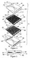
Fig. 2 is an exploded view of the manifold adaptor plate of this invention. -
Fig. 3 is a cross sectional view of a portion of the manifold adaptor plate ofFig. 2 . -
Fig. 4 is an exploded view of an alternative manifold adaptor plate of this invention. -
Fig. 5 is a partial cross sectional view of the manifold adaptor ofFig. 4 . -
Fig. 6 is an exploded view of a filtration module manifold and the manifold adaptor plate with this invention. -
Fig. 7 illustrates the function of a filtration module suitable for use with this invention. -
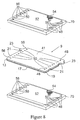
Fig. 8 is an exploded view of the manifold adaptor plate of the present invention and two filtration modules. -
Fig 9 and 9A is a partial cross sectional view of an alternative embodiment of the manifold adaptor plate of the present invention. - Referring to
Fig. 1 , amanifold apparatus 1 within which the manifold adaptor plate of this invention can be incorporated includes a first set ofmanifold segments feed manifold segment 6 and a second set ofmanifold segments manifold frame 12. The first set ofmanifold segments filtrate outlet 14 and aretentate vent 16. The second set ofmanifold segments filtrate outlet 18 and aretentate drain 20. Theretentate drain 20 and retentatevent 16 are capped during filtration. Theretentate vent 16 permits filling the retentate flow path with liquid and the retentate drain permits draining the apparatus of retentate upon completion of the filtration. Thefeed segment 6 is provided with afeed inlet 22 and aretentate outlet 25. The feed inlet can have a diameter larger than that of internal feed conduits within the manifold segments since the incoming feed is split into the first set ofmanifold segments segments filtration modules 24 are secured to manifoldsegments plates 26 and a plurality ofcompression assemblies 28 such as bolts. Alternatively, threaded rods having nuts on their ends can be utilized rather than bolts. The manifold adaptor plate 11 (Fig. 6 ) of this invention is positioned between thefiltration modules 24 and themanifold segments - Referring to
Figs. 2 and 3 manifold adaptor plate 11 of this invention consists ofpolymeric sheet 13, arigid plate 19 that is formed of a thermosetting resin, reinforced composites such as graphite or carbon composites or a metal such as stainless steel, Hastelloy metal or aluminum and anelastomeric layer 17. Therigid plate 19 has two major surfaces, 7A and 7B, respectively. The polymeric sheet is arranged to be in contact with one major surface of the rigid plate, in the instance ofFigs 2 and 3 with the firstmajor surface 7A while theelastomeric layer 17 is arranged to be in contact with the other major surface that is opposite the first surface, in the instance ofFigs 2 and 3 with the secondmajor surface 7B. Eachlayer plate 11. The holes of eachlayer layer holes 50 for filtrate withholes 56 for retentate. The opposing edge is provided withholes 48 for feed which alternate withholes 50 for filtrate. As shown inFig. 3 which is a close up of the assembledplate 11 shown through one hole, in thiscase hole 50, theelastomeric layer 17 extends through eachhole protrusions 15 that extend over and bind topolymeric sheet 13. Preferably, themanifold adaptor plate 11 is provided with fourindentations 21 which permit theplate 11 to be hung on bolts 28 (Fig. 1 ), however this is not required and other means can used instead.Tabs 23 can also be provided to facilitate assembly ofplate 11 ontobolts 28 and removed of theplate 11 frombolts 28. - The
elastomeric layer 17 andpolymeric sheet 13 are of different material but are matched so that the two layers are bound to each other when theelastomeric layer 17 is molded. Optionally, the elastomeric layer can be bonded to the surface of the rigid plate against which it is applied. As optionally, the polymeric sheet instead of being a separate layer can be cast or otherwise formed on the surface of the rigid plate against which it is applied. The seal is formed of any elastomeric material. The elastomeric material does not need to be very elastic but it should have some ability to maintain the seal with the adjacent layers during flexion or compression. It has a durometer of from about 60 to about 100 Shore A. - Suitable materials include but are not limited to thermoplastics, such as polyethylene, polypropylene, EVA copolymers, alpha olefins and metallocene copolymers, PFA, MFA, polycarbonate, vinyl copolymers such as PVC, polyamides such as nylon, polyesters, acrylonitrile-butadienestyrene (ABS), polysulphone, polyethersulphone, polyarylsulphone, polyphenylsulphone, polyacrylonitrile, polyvinylidene fluoride (PVDF), and blends thereof, thermoplastic elastomers which can be formed of styrenic block copolymers, blends of EPDM and polypropylene and the like and which are sold under brand names such as Santoprene® polymer, Kraton® thermoplastic elastomer and Dynaflex® elastomer, EPDM rubber, thermosets such as closed cell foamed urethanes, and rubbers, either natural or synthetic.
- It is preferred that the material be a thermoplastic or thermoplastic elastomer so as to allow for its use in the preferred method of this invention, injection molding. Additional, thermoplastics and thermoplastic elastomers have lower levels of extractables making the filtered product cleaner. Exemplary preferred material include SANTOPRENE® polymer with a durometer of about 80 available from Advanced Elastomer Systems of Akron, Ohio or the thermoplastic elastomer Kraton® elastomer G27052 with a Shore A hardness of 56, available from Advanced Elastomer Systems located at Akron Ohio. Preferred thermoplastics include low density, linear low density, medium density and high density polyethylene, polypropylene and EVA copolymers.
- Representative suitable polymeric sheets include polypropylene, polyethelyne, polyester, polysulfone, polyamide, acetal (i.e. polyacetal), acrylic (i.e. polyacrylic), polystyrene, PTFE, silicone , vinyl (i.e. polyvinyl) or the like, representative suitable rigid layers include stainless steel, steel, aluminum, phenol-formaldehyde, urea-formaldehyde, carbon/epoxy composites, graphite/epoxy composites, rigid molded plastic, glass or fiber filled plastic or the like.
- Referring to
Figs. 4 and 5 , the alternativemanifold adaptor plate 9 of this invention includes twoelastomeric layers polymeric sheet 13 andrigid plate 19. Theelastomeric layers holes surfaces rigid plate 19 as well as on only onesurface 7A ofplate 19 as shown inFig. 4 . Like reference numbers inFigs. 4 and 5 refer to like elements ofFigs. 2 and 3 . As shown inFig. 5 ,elastomeric layer 41 coatspolymeric sheet 13 andelastomeric layer 17 coatspolymeric sheet 13. In addition,elastomeric layers holes 50 as well as withinholes layer 41,Fig. 4 ) or can comprise protrusions (protrusions 15,Figs. 2 and 3 ). - Referring to
Fig. 6 , a filtration module useful with the manifold adaptor plate of this invention is described. Afiltration element 70 is positioned betweenmanifold segment 51 andplate 55.Manifold segment 51 is provided withliquid inlet 73,filtrate outlets retentate outlet 81. Themanifold segment 51 includes a plurality of feed inlet means 33 and a plurality of retentate outlet means 26. One set of filtrate outlet means 28 is provided on one end of themanifold segment 51 while a second set of filtrate outlet means 28 is provided on the opposite end ofmanifold segment 51. The filtrate outlet means 28 are connected to filtrateoutlets paths 46 are of a size which permits filtrate to flow therethrough while avoiding sagging of a filtrate screen (not shown) into thepaths 46, typically about 0.15 to 0.3 cm (0.06 to 0.12 inch) wide. Thefiltration module 70 includesholes 48 which communicate with feed inlet means 33 and holes 50 which communicate with filtrate outlet means 28. The manifold adaptor plate 11 (Fig. 2 ) is positioned so that theelastomeric layer 17 contactsmanifold segment 51 so that proper sealing is effected which prevents admixture of filtrate with either feed or retentate. As seen inFig. 7 , thefiltrate side 52 of thefilter layer 53 havingmesh spacer 54 in contact therewith is exposed. Thefiltration segment 70 is also provided withholes 56 which communicate with retentate outlet means 26. Theplate 55 serves as a seal for the top surface of thefiltration module 70. - Referring to
Fig. 7 , thefiltration module 70 includes afiltrate spacer 54, afilter layer 52, aretentate spacer 60 and afilter layer 62 with a second filtrate spacer 54 (not shown) and which can contactpaths 46. The liquid feed represented byarrow 58 passes throughholes 48 inlayer 62 intospacer 60. A portion of the liquid passes throughspacer 60, as represented byarrow 64 and throughfilter 52 as represented byarrow 66. The remaining portion of the incoming liquid passes upwardly as represented byarrow 68, throughholes 48 infiltrate spacer 54 and into the next adjacent filtration module (not shown) wherein it proceeds as described above with reference tofiltration module 70. The filtrate passes intoholes 50 and passes in a direction as shown byarrows Fig. 6 ). The retentate passes acrossretentate spacer 60 as shown byarrows holes 56 and to retentate outlet means 26 (Fig. 6 ) in a direction as shown byarrow 78. The filtrate passes intoholes 28,grooves 46, outlet means 29 (Fig. 6 ) towardfiltrate outlets holes 26 and toretentate outlet 81. - As shown in
Fig. 8 , the adaptor plate 9 (Fig. 4 ) is positioned between two filtration modules (Fig. 6 ) so thatelastomeric layer 41 andelastomeric layer 17 provide the sealing function. - Referring to
Figs 1 ,6 and7 , themanifold apparatus 1 which utilizes themanifold adaptor plate 11 of this invention is utilized as follows: The liquid feed to be filtered passes into feed inlet 22(Fig. 1 ), into liquid inlet 73 (Fig. 6 ), through feed inlet means 33, throughfeed inlets 48 and throughfiltration module 70 to separate feed into filtrate and retentate. Retentate is removed fromfiltration modules 70, throughholes 56, throughholes 26 and throughoutlet 81. Filtrate is removed fromfiltration modules 70 throughholes 50, alongpaths 46 and throughoutlets - In a further embodiment of any the embodiments mentioned above, one can block or close off one or more of the holes in the plate with the elastomeric material to form a flow diverter. Generally, all the holes of at least one type (feed, retentate or permeate) or all holes (feed, permeate and retentate if used) are blocked. More preferably, the hole(s) are blocked by filling them with a volume of elastomeric material sufficient to prevent liquid flow through it.
- In one embodiment of this design, as shown in
Figure 9 , one uses apolymeric sheet 112 on a firstmajor surface 111 of arigid plate 110 and theelastomeric material 114 on the othermajor surface 113 and extending through the hole(s) 116 to overlay aportion 118 of thesheet 112 adjacent the hole(s) 116. The amount of elastomeric material used is sufficient to fill the hole(s) 116 and render it incapable of passing fluid from onemajor surface 111 to the other 113. - In
Figure 9A , is shown another embodiment in which theplate 120 is simply designed as a flow diverter and has no holes at least at those locations where the flow is to be diverted. Thepolymeric sheet 122 does haveholes 124 and is attached to thediverter plate 120 by the use of theelastomeric material 126 in and around theholes 124 in thesheet 122. Asealing layer 128 is formed on the opposite face of theplate 120 as has been described above.
Claims (8)
- A manifold adaptor plate (11) comprising:an intermediate rigid plate (19) having two major surfaces (7A,7B),a separate polymeric sheet (13) arranged in contact with one of the major surfaces (7A,7B) of said rigid plate (19), andan elastomeric layer (17) arranged on the side of the other one of the major surfaces (7A, 7B) of said rigid plate (19),wherein the elastomeric material of said elastomeric layer (17) has a hardness of from about 60 to about 100 Shore A,wherein said intermediate rigid plate (19) is formed of a thermosetting resin, reinforced composites or a metal,wherein each of said rigid plate (19), said polymeric sheet (13) and said elastomeric layer (17) is provided with holes (48,50,56) and wherein the holes (48,50,56) are in register with each other to define liquid pathways through the plate (11), andwherein said elastomeric layer (17) extends through each of the holes (48,50,56) and forms protrusions (15) that extend over and bind to said polymeric sheet (13) at the periphery of said holes (48,50,56).
- A manifold adaptor plate (9) comprising:an intermediate rigid plate (19) having two major surfaces (7A, 7B),a separate polymeric sheet (13) arranged in contact with one of the major surfaces (7A, 7B) of said rigid plate (19), and
- The manifold adaptor plate (9) according to claim 2, comprising a further separate polymeric sheet arranged in contact with the other one of the major surfaces (7A, 7B) of said rigid plate (19).
- The manifold adaptor plate of any one of claims 1 to 3, wherein the elastomeric layer(s) (17,41) is/are of a volume sufficient to close off one or more of the liquid pathways.
- The manifold adaptor plate of any one of claims 1 to 4, wherein the elastomeric layer(s) is/are formed of a thermoplastic elastomer.
- The manifold adaptor plate of any one of claims 1 to 5, wherein the polymeric sheet(s) (13) is/are formed from polypropylene.
- The manifold adaptor plate of any one of claims 1 to 6, wherein the intermediate rigid plate (19) is formed of a graphite or carbon composite or of stainless steel, steel or aluminum.
- A manifold apparatus (1) within which one or plural adaptor plate(s) (9;11) as defined in any one of claims 1 to 7 is/are incorporated.
a first elastomeric layer (17) arranged on the side of the other one of the major surfaces (7A,7B) of said rigid plate (19), and
a second elastomeric layer (41) arranged on the side of the one of the major surfaces (7A,7B) of said rigid plate (19),
wherein the elastomeric material of said elastomeric layers (17;41) has a hardness of from about 60 to about 100 Shore A,
wherein said intermediate rigid plate (19) is formed of a thermosetting resin, reinforced composites or a metal,
wherein each of said rigid plate (19), said polymeric sheet (13) and said elastomeric layers (17,41) are provided with holes (48,50,56) and wherein the holes (48,50,56) are in register with each other to define liquid pathways through the plate (9), and
wherein said first elastomeric layer (17) extends through each of the holes (48,50,56), is bound to said polymeric sheet (13), and is bound to said second elastomeric layer (17,41) within said holes (48,50,56).
Priority Applications (1)
| Application Number | Priority Date | Filing Date | Title |
|---|---|---|---|
| EP10178438.7A EP2269715B1 (en) | 2006-07-28 | 2007-07-23 | Manifold adaptor plate for filtration apparatus |
Applications Claiming Priority (2)
| Application Number | Priority Date | Filing Date | Title |
|---|---|---|---|
| US83389106P | 2006-07-28 | 2006-07-28 | |
| US92705807P | 2007-05-01 | 2007-05-01 |
Related Child Applications (2)
| Application Number | Title | Priority Date | Filing Date |
|---|---|---|---|
| EP10178438.7A Division EP2269715B1 (en) | 2006-07-28 | 2007-07-23 | Manifold adaptor plate for filtration apparatus |
| EP10178438.7 Division-Into | 2010-09-22 |
Publications (2)
| Publication Number | Publication Date |
|---|---|
| EP1882513A1 EP1882513A1 (en) | 2008-01-30 |
| EP1882513B1 true EP1882513B1 (en) | 2011-06-01 |
Family
ID=39206140
Family Applications (2)
| Application Number | Title | Priority Date | Filing Date |
|---|---|---|---|
| EP10178438.7A Active EP2269715B1 (en) | 2006-07-28 | 2007-07-23 | Manifold adaptor plate for filtration apparatus |
| EP07112936A Active EP1882513B1 (en) | 2006-07-28 | 2007-07-23 | Manifold adaptor plate for filtration apparatus |
Family Applications Before (1)
| Application Number | Title | Priority Date | Filing Date |
|---|---|---|---|
| EP10178438.7A Active EP2269715B1 (en) | 2006-07-28 | 2007-07-23 | Manifold adaptor plate for filtration apparatus |
Country Status (6)
| Country | Link |
|---|---|
| US (2) | US7959805B2 (en) |
| EP (2) | EP2269715B1 (en) |
| JP (1) | JP4368914B2 (en) |
| CN (1) | CN101143302B (en) |
| ES (1) | ES2367394T3 (en) |
| SG (1) | SG139658A1 (en) |
Families Citing this family (20)
| Publication number | Priority date | Publication date | Assignee | Title |
|---|---|---|---|---|
| KR100954102B1 (en) * | 2008-09-25 | 2010-04-23 | 메타워터 가부시키가이샤 | Filtering and condensing apparatus of suction type |
| WO2010035362A1 (en) * | 2008-09-25 | 2010-04-01 | メタウォーター株式会社 | Suction type filtering-condensing apparatus |
| JP5377452B2 (en) * | 2009-10-16 | 2013-12-25 | 日東電工株式会社 | Manufacturing method of composite semipermeable membrane |
| US9101883B2 (en) | 2009-11-28 | 2015-08-11 | Smartflow Technologies, Inc. | Portable filtration unit |
| US8980088B2 (en) | 2011-04-19 | 2015-03-17 | Pall Corporation | Fluid treatment arrangements and methods of making fluid treatment arrangements |
| DE102012213442A1 (en) * | 2012-07-31 | 2014-02-27 | Zf Friedrichshafen Ag | base element |
| US20140042072A1 (en) * | 2012-08-10 | 2014-02-13 | Pall Corporation | Fluid treatment assemblies, fluid treatment segments, and methods of making fluid treatment systems |
| CN103752056B (en) * | 2013-12-28 | 2016-08-17 | 杭州兴源过滤科技股份有限公司 | Arogel filtering board, arogel pressure filter and filtration discharge method |
| US10550148B2 (en) | 2014-06-16 | 2020-02-04 | Emd Millipore Corporation | Methods for increasing the capacity of flow-through processes |
| WO2015195452A2 (en) | 2014-06-16 | 2015-12-23 | Emd Millipore Corporation | Single-pass filtration systems and processes |
| CN115463546A (en) | 2014-06-25 | 2022-12-13 | Emd 密理博公司 | Filter element, tangential flow filtration system, method of producing a feed screen |
| ES2935333T3 (en) | 2014-08-29 | 2023-03-06 | Emd Millipore Corp | Processes for filtering liquids using single pass tangential flow filtration systems and tangential flow filtration systems with recirculation of retentate |
| CN105745009B (en) | 2014-08-29 | 2018-09-28 | Emd 密理博公司 | Single-pass tangential flow filtration systems and tangential flow filtration systems with recirculation of retentate |
| USD762811S1 (en) | 2014-12-18 | 2016-08-02 | Emd Millipore Corporation | Diverter plate |
| USD761381S1 (en) | 2014-12-18 | 2016-07-12 | Emd Millipore Corporation | Retentate plate |
| EP3285901B1 (en) * | 2015-04-24 | 2024-08-14 | Evoqua Water Technologies LLC | Structures for normalizing multi-planar flow distribution within an electrochemical separation system |
| CA3023486C (en) | 2016-06-09 | 2022-03-29 | Emd Millipore Corporation | Radial-path filter elements, systems and methods of using same |
| US10632461B2 (en) * | 2016-09-30 | 2020-04-28 | Canon Medical Systems Corporation | Chemical container |
| CN116407952A (en) * | 2023-04-11 | 2023-07-11 | 杭州科百特过滤器材有限公司 | Filtering membrane bag |
| USD1123181S1 (en) * | 2024-11-15 | 2026-04-21 | Cytiva Us Llc | Tangential flow filtration cassette |
Family Cites Families (18)
| Publication number | Priority date | Publication date | Assignee | Title |
|---|---|---|---|---|
| JPS4916189B1 (en) | 1970-12-23 | 1974-04-20 | ||
| US3661721A (en) * | 1971-02-05 | 1972-05-09 | Pactide Corp | Compact multistage distillation apparatus having stacked microporous membranes and impermeable films |
| BE794634A (en) | 1972-01-28 | 1973-07-26 | Rhone Poulenc Sa | DIAPHRAGM SEPARATOR |
| JPS53103983A (en) | 1977-02-23 | 1978-09-09 | Kanegafuchi Chem Ind Co Ltd | Separating apparatus for liquid |
| GB2093369B (en) * | 1980-09-03 | 1984-07-18 | Nemtec Lab Pty Ltd | Fluid treatment apparatus |
| DE4002295A1 (en) | 1990-01-26 | 1991-08-01 | Geesthacht Gkss Forschung | SEALING FRAME FOR MEMBRANE STACK |
| US5147542A (en) | 1991-02-04 | 1992-09-15 | Millipore Corporation | Manifold and manifold segment for tangential flow filtration apparatus |
| US5176828A (en) * | 1991-02-04 | 1993-01-05 | Millipore Corporation | Manifold segment stack with intermediate feed manifold |
| NZ247276A (en) * | 1992-04-06 | 1994-12-22 | Westvaco Corp | Production of papermaking fibre of low lignin content from recycled high lignin waste paper; mixtures with fresh pulp and products produced therefrom |
| DE4330840C1 (en) | 1993-09-11 | 1995-02-16 | Hengst Walter Gmbh & Co Kg | Filter for cleaning liquids |
| US5599447A (en) * | 1995-06-06 | 1997-02-04 | Millipore Investment Holdings Limited | Manifold apparatus for tangential flow filtration apparatus |
| DE19827473C1 (en) | 1998-06-19 | 1999-08-26 | Sartorius Gmbh | Cross flow filter cartridge suiting diverse range of medical, industrial and laboratory applications |
| JP3881548B2 (en) | 1999-06-22 | 2007-02-14 | ミリポア・コーポレイション | Sealing device for filtration equipment |
| US20020139741A1 (en) * | 2001-03-27 | 2002-10-03 | Henry Kopf | Integral gasketed filtration cassette article and method of making the same |
| KR20040021619A (en) | 2001-06-28 | 2004-03-10 | 마이크롤리스 코포레이션 | Filtration module including unitary filter cartridge-bowl construction |
| ATE553835T1 (en) * | 2001-09-20 | 2012-05-15 | Emd Millipore Corp | FILTER MODULE |
| US6758954B2 (en) * | 2002-04-11 | 2004-07-06 | U.S. Filter Corporation | Electrodeionization apparatus with resilient endblock |
| US6830683B2 (en) * | 2002-04-23 | 2004-12-14 | Culligan International Company | Filter cartridge assembly with brine seal and retaining ring |
-
2007
- 2007-07-09 US US11/825,746 patent/US7959805B2/en active Active
- 2007-07-12 SG SG200705176-6A patent/SG139658A1/en unknown
- 2007-07-19 JP JP2007188348A patent/JP4368914B2/en active Active
- 2007-07-23 ES ES07112936T patent/ES2367394T3/en active Active
- 2007-07-23 EP EP10178438.7A patent/EP2269715B1/en active Active
- 2007-07-23 EP EP07112936A patent/EP1882513B1/en active Active
- 2007-07-26 CN CN2007101369884A patent/CN101143302B/en active Active
-
2011
- 2011-06-03 US US13/152,866 patent/US20110266204A1/en not_active Abandoned
Also Published As
| Publication number | Publication date |
|---|---|
| CN101143302A (en) | 2008-03-19 |
| EP2269715B1 (en) | 2018-05-30 |
| EP2269715A1 (en) | 2011-01-05 |
| JP4368914B2 (en) | 2009-11-18 |
| US7959805B2 (en) | 2011-06-14 |
| CN101143302B (en) | 2011-08-31 |
| SG139658A1 (en) | 2008-02-29 |
| ES2367394T3 (en) | 2011-11-03 |
| EP1882513A1 (en) | 2008-01-30 |
| JP2008030032A (en) | 2008-02-14 |
| US20110266204A1 (en) | 2011-11-03 |
| US20080029451A1 (en) | 2008-02-07 |
Similar Documents
| Publication | Publication Date | Title |
|---|---|---|
| EP2269715B1 (en) | Manifold adaptor plate for filtration apparatus | |
| US8007670B2 (en) | Laminated cassette device and methods for making same | |
| EP0238737B1 (en) | Membrane assembly for fluid separation-disk | |
| CN101820967B (en) | filter | |
| US9669333B2 (en) | Filter module and modular filter system | |
| AU2019390413B2 (en) | Single use aseptic tangential flow filtration systems and methods | |
| JP2014036953A (en) | Fluid treatment assembly, fluid treatment segment and method for manufacturing fluid treatment system | |
| EP1196229B1 (en) | Filtration devices comprising a sealing gasket | |
| WO2014066035A2 (en) | Filtration element with end cap and face seal | |
| US20050126981A1 (en) | Plastic encapsulated tangential flow filter device and methods for making same | |
| US20060125187A1 (en) | Sealing device for filtration devices | |
| US6251271B1 (en) | Device for purifying a fluid | |
| JP7311092B2 (en) | Tangential flow filtration system and tangential flow filtration cassette | |
| US20050056966A1 (en) | Filtration devices comprising a sealing gasket | |
| ES2684143T3 (en) | Adapter plate for filter device manifold | |
| CN120112742A (en) | Rotary valve | |
| WO2026104514A1 (en) | Filtration device and components thereof | |
| USH2168H1 (en) | Arrangement and construction of an element bundling module | |
| WO2026104512A1 (en) | Filtration apparatus, system and method |
Legal Events
| Date | Code | Title | Description |
|---|---|---|---|
| PUAI | Public reference made under article 153(3) epc to a published international application that has entered the european phase |
Free format text: ORIGINAL CODE: 0009012 |
|
| AK | Designated contracting states |
Kind code of ref document: A1 Designated state(s): AT BE BG CH CY CZ DE DK EE ES FI FR GB GR HU IE IS IT LI LT LU LV MC MT NL PL PT RO SE SI SK TR |
|
| AX | Request for extension of the european patent |
Extension state: AL BA HR MK YU |
|
| 17P | Request for examination filed |
Effective date: 20080704 |
|
| 17Q | First examination report despatched |
Effective date: 20080804 |
|
| AKX | Designation fees paid |
Designated state(s): AT BE BG CH CY CZ DE DK EE ES FI FR GB GR HU IE IS IT LI LT LU LV MC MT NL PL PT RO SE SI SK TR |
|
| GRAP | Despatch of communication of intention to grant a patent |
Free format text: ORIGINAL CODE: EPIDOSNIGR1 |
|
| GRAS | Grant fee paid |
Free format text: ORIGINAL CODE: EPIDOSNIGR3 |
|
| GRAA | (expected) grant |
Free format text: ORIGINAL CODE: 0009210 |
|
| AK | Designated contracting states |
Kind code of ref document: B1 Designated state(s): AT BE BG CH CY CZ DE DK EE ES FI FR GB GR HU IE IS IT LI LT LU LV MC MT NL PL PT RO SE SI SK TR |
|
| REG | Reference to a national code |
Ref country code: GB Ref legal event code: FG4D |
|
| REG | Reference to a national code |
Ref country code: CH Ref legal event code: EP |
|
| REG | Reference to a national code |
Ref country code: IE Ref legal event code: FG4D |
|
| REG | Reference to a national code |
Ref country code: CH Ref legal event code: NV Representative=s name: E. BLUM & CO. AG PATENT- UND MARKENANWAELTE VSP |
|
| REG | Reference to a national code |
Ref country code: DE Ref legal event code: R096 Ref document number: 602007014932 Country of ref document: DE Effective date: 20110714 |
|
| REG | Reference to a national code |
Ref country code: NL Ref legal event code: T3 |
|
| PG25 | Lapsed in a contracting state [announced via postgrant information from national office to epo] |
Ref country code: SE Free format text: LAPSE BECAUSE OF FAILURE TO SUBMIT A TRANSLATION OF THE DESCRIPTION OR TO PAY THE FEE WITHIN THE PRESCRIBED TIME-LIMIT Effective date: 20110601 Ref country code: LT Free format text: LAPSE BECAUSE OF FAILURE TO SUBMIT A TRANSLATION OF THE DESCRIPTION OR TO PAY THE FEE WITHIN THE PRESCRIBED TIME-LIMIT Effective date: 20110601 |
|
| REG | Reference to a national code |
Ref country code: ES Ref legal event code: FG2A Ref document number: 2367394 Country of ref document: ES Kind code of ref document: T3 Effective date: 20111103 |
|
| PG25 | Lapsed in a contracting state [announced via postgrant information from national office to epo] |
Ref country code: SI Free format text: LAPSE BECAUSE OF FAILURE TO SUBMIT A TRANSLATION OF THE DESCRIPTION OR TO PAY THE FEE WITHIN THE PRESCRIBED TIME-LIMIT Effective date: 20110601 Ref country code: CY Free format text: LAPSE BECAUSE OF FAILURE TO SUBMIT A TRANSLATION OF THE DESCRIPTION OR TO PAY THE FEE WITHIN THE PRESCRIBED TIME-LIMIT Effective date: 20110601 Ref country code: GR Free format text: LAPSE BECAUSE OF FAILURE TO SUBMIT A TRANSLATION OF THE DESCRIPTION OR TO PAY THE FEE WITHIN THE PRESCRIBED TIME-LIMIT Effective date: 20110902 Ref country code: FI Free format text: LAPSE BECAUSE OF FAILURE TO SUBMIT A TRANSLATION OF THE DESCRIPTION OR TO PAY THE FEE WITHIN THE PRESCRIBED TIME-LIMIT Effective date: 20110601 Ref country code: LV Free format text: LAPSE BECAUSE OF FAILURE TO SUBMIT A TRANSLATION OF THE DESCRIPTION OR TO PAY THE FEE WITHIN THE PRESCRIBED TIME-LIMIT Effective date: 20110601 Ref country code: AT Free format text: LAPSE BECAUSE OF FAILURE TO SUBMIT A TRANSLATION OF THE DESCRIPTION OR TO PAY THE FEE WITHIN THE PRESCRIBED TIME-LIMIT Effective date: 20110601 |
|
| PG25 | Lapsed in a contracting state [announced via postgrant information from national office to epo] |
Ref country code: MT Free format text: LAPSE BECAUSE OF FAILURE TO SUBMIT A TRANSLATION OF THE DESCRIPTION OR TO PAY THE FEE WITHIN THE PRESCRIBED TIME-LIMIT Effective date: 20110601 |
|
| PG25 | Lapsed in a contracting state [announced via postgrant information from national office to epo] |
Ref country code: EE Free format text: LAPSE BECAUSE OF FAILURE TO SUBMIT A TRANSLATION OF THE DESCRIPTION OR TO PAY THE FEE WITHIN THE PRESCRIBED TIME-LIMIT Effective date: 20110601 Ref country code: PT Free format text: LAPSE BECAUSE OF FAILURE TO SUBMIT A TRANSLATION OF THE DESCRIPTION OR TO PAY THE FEE WITHIN THE PRESCRIBED TIME-LIMIT Effective date: 20111003 Ref country code: IS Free format text: LAPSE BECAUSE OF FAILURE TO SUBMIT A TRANSLATION OF THE DESCRIPTION OR TO PAY THE FEE WITHIN THE PRESCRIBED TIME-LIMIT Effective date: 20111001 Ref country code: CZ Free format text: LAPSE BECAUSE OF FAILURE TO SUBMIT A TRANSLATION OF THE DESCRIPTION OR TO PAY THE FEE WITHIN THE PRESCRIBED TIME-LIMIT Effective date: 20110601 |
|
| PG25 | Lapsed in a contracting state [announced via postgrant information from national office to epo] |
Ref country code: PL Free format text: LAPSE BECAUSE OF FAILURE TO SUBMIT A TRANSLATION OF THE DESCRIPTION OR TO PAY THE FEE WITHIN THE PRESCRIBED TIME-LIMIT Effective date: 20110601 Ref country code: MC Free format text: LAPSE BECAUSE OF NON-PAYMENT OF DUE FEES Effective date: 20110731 Ref country code: RO Free format text: LAPSE BECAUSE OF FAILURE TO SUBMIT A TRANSLATION OF THE DESCRIPTION OR TO PAY THE FEE WITHIN THE PRESCRIBED TIME-LIMIT Effective date: 20110601 Ref country code: SK Free format text: LAPSE BECAUSE OF FAILURE TO SUBMIT A TRANSLATION OF THE DESCRIPTION OR TO PAY THE FEE WITHIN THE PRESCRIBED TIME-LIMIT Effective date: 20110601 |
|
| REG | Reference to a national code |
Ref country code: CH Ref legal event code: PFA Owner name: EMD MILLIPORE CORPORATION Free format text: MILLIPORE CORPORATION#290 CONCORD ROAD#BILLERICA MASSACHUSETTS 01821 (US) -TRANSFER TO- EMD MILLIPORE CORPORATION#290 CONCORD ROAD#BILLERICA, MA 01821 (US) |
|
| REG | Reference to a national code |
Ref country code: NL Ref legal event code: TD Effective date: 20120227 |
|
| PLBE | No opposition filed within time limit |
Free format text: ORIGINAL CODE: 0009261 |
|
| STAA | Information on the status of an ep patent application or granted ep patent |
Free format text: STATUS: NO OPPOSITION FILED WITHIN TIME LIMIT |
|
| REG | Reference to a national code |
Ref country code: IE Ref legal event code: MM4A |
|
| REG | Reference to a national code |
Ref country code: ES Ref legal event code: PC2A Owner name: EMD MILLIPORE CORPORATION Effective date: 20120416 |
|
| REG | Reference to a national code |
Ref country code: FR Ref legal event code: CD Owner name: EMD MILLIPORE CORPORATION Effective date: 20120327 |
|
| 26N | No opposition filed |
Effective date: 20120302 |
|
| REG | Reference to a national code |
Ref country code: DE Ref legal event code: R082 Ref document number: 602007014932 Country of ref document: DE Representative=s name: HENKEL, BREUER & PARTNER, DE |
|
| REG | Reference to a national code |
Ref country code: DE Ref legal event code: R097 Ref document number: 602007014932 Country of ref document: DE Effective date: 20120302 |
|
| PG25 | Lapsed in a contracting state [announced via postgrant information from national office to epo] |
Ref country code: DK Free format text: LAPSE BECAUSE OF FAILURE TO SUBMIT A TRANSLATION OF THE DESCRIPTION OR TO PAY THE FEE WITHIN THE PRESCRIBED TIME-LIMIT Effective date: 20110601 |
|
| PG25 | Lapsed in a contracting state [announced via postgrant information from national office to epo] |
Ref country code: IE Free format text: LAPSE BECAUSE OF NON-PAYMENT OF DUE FEES Effective date: 20110723 |
|
| REG | Reference to a national code |
Ref country code: DE Ref legal event code: R082 Ref document number: 602007014932 Country of ref document: DE Representative=s name: PATENTANWAELTE HENKEL, BREUER & PARTNER, DE Effective date: 20120613 Ref country code: DE Ref legal event code: R081 Ref document number: 602007014932 Country of ref document: DE Owner name: EMD MILLIPORE CORPORATION, BILLERICA, US Free format text: FORMER OWNER: MILLIPORE CORP., BILLERICA, MASS., US Effective date: 20120613 Ref country code: DE Ref legal event code: R082 Ref document number: 602007014932 Country of ref document: DE Representative=s name: PATENTANWAELTE HENKEL, BREUER & PARTNER MBB, DE Effective date: 20120613 |
|
| PG25 | Lapsed in a contracting state [announced via postgrant information from national office to epo] |
Ref country code: LU Free format text: LAPSE BECAUSE OF NON-PAYMENT OF DUE FEES Effective date: 20110723 |
|
| PG25 | Lapsed in a contracting state [announced via postgrant information from national office to epo] |
Ref country code: BG Free format text: LAPSE BECAUSE OF FAILURE TO SUBMIT A TRANSLATION OF THE DESCRIPTION OR TO PAY THE FEE WITHIN THE PRESCRIBED TIME-LIMIT Effective date: 20110901 |
|
| PG25 | Lapsed in a contracting state [announced via postgrant information from national office to epo] |
Ref country code: TR Free format text: LAPSE BECAUSE OF FAILURE TO SUBMIT A TRANSLATION OF THE DESCRIPTION OR TO PAY THE FEE WITHIN THE PRESCRIBED TIME-LIMIT Effective date: 20110601 |
|
| PG25 | Lapsed in a contracting state [announced via postgrant information from national office to epo] |
Ref country code: HU Free format text: LAPSE BECAUSE OF FAILURE TO SUBMIT A TRANSLATION OF THE DESCRIPTION OR TO PAY THE FEE WITHIN THE PRESCRIBED TIME-LIMIT Effective date: 20110601 |
|
| REG | Reference to a national code |
Ref country code: FR Ref legal event code: PLFP Year of fee payment: 10 |
|
| REG | Reference to a national code |
Ref country code: FR Ref legal event code: PLFP Year of fee payment: 11 |
|
| REG | Reference to a national code |
Ref country code: FR Ref legal event code: PLFP Year of fee payment: 12 |
|
| P01 | Opt-out of the competence of the unified patent court (upc) registered |
Effective date: 20230602 |
|
| PGFP | Annual fee paid to national office [announced via postgrant information from national office to epo] |
Ref country code: GB Payment date: 20250619 Year of fee payment: 19 |
|
| PGFP | Annual fee paid to national office [announced via postgrant information from national office to epo] |
Ref country code: NL Payment date: 20250620 Year of fee payment: 19 Ref country code: BE Payment date: 20250619 Year of fee payment: 19 |
|
| PGFP | Annual fee paid to national office [announced via postgrant information from national office to epo] |
Ref country code: FR Payment date: 20250620 Year of fee payment: 19 |
|
| PGFP | Annual fee paid to national office [announced via postgrant information from national office to epo] |
Ref country code: ES Payment date: 20250801 Year of fee payment: 19 |
|
| PGFP | Annual fee paid to national office [announced via postgrant information from national office to epo] |
Ref country code: DE Payment date: 20250620 Year of fee payment: 19 |
|
| PGFP | Annual fee paid to national office [announced via postgrant information from national office to epo] |
Ref country code: IT Payment date: 20250619 Year of fee payment: 19 |
|
| PGFP | Annual fee paid to national office [announced via postgrant information from national office to epo] |
Ref country code: CH Payment date: 20250801 Year of fee payment: 19 |