EP1881745A1 - Process for recognizing the supply power discharge lamps and related device - Google Patents
Process for recognizing the supply power discharge lamps and related device Download PDFInfo
- Publication number
- EP1881745A1 EP1881745A1 EP06425504A EP06425504A EP1881745A1 EP 1881745 A1 EP1881745 A1 EP 1881745A1 EP 06425504 A EP06425504 A EP 06425504A EP 06425504 A EP06425504 A EP 06425504A EP 1881745 A1 EP1881745 A1 EP 1881745A1
- Authority
- EP
- European Patent Office
- Prior art keywords
- lamp
- conduction time
- correction
- ton
- power
- Prior art date
- Legal status (The legal status is an assumption and is not a legal conclusion. Google has not performed a legal analysis and makes no representation as to the accuracy of the status listed.)
- Granted
Links
Images



Classifications
-
- H—ELECTRICITY
- H05—ELECTRIC TECHNIQUES NOT OTHERWISE PROVIDED FOR
- H05B—ELECTRIC HEATING; ELECTRIC LIGHT SOURCES NOT OTHERWISE PROVIDED FOR; CIRCUIT ARRANGEMENTS FOR ELECTRIC LIGHT SOURCES, IN GENERAL
- H05B41/00—Circuit arrangements or apparatus for igniting or operating discharge lamps
- H05B41/14—Circuit arrangements
- H05B41/36—Controlling
Definitions
- the present invention relates to techniques that enable recognition of the power of discharge lamps and has been developed with particular attention paid to its possible use in electronic devices designed to supply such lamps.
- Discharge lamps such as fluorescent lamps and high-intensity discharge lamps (HIDs) are among the most popular in view of their luminous efficiency, their good chromatic yield and their long life as compared to incandescent lamps.
- lamps are not able to operate if connected directly to the power supply network.
- said lamps require the use of intermediate devices, such as, for example, electronic power supplies, which are able to perform the following functions:
- the devices for the power supplying of discharge lamps are divided into two types: electromagnetic and electronic.
- the electronic devices offer, as compared to magnetic ones, the following advantages:
- these devices are designed for driving one and the same type of lamp or at the most a set of lamps with a fixed and defined power.
- the a.c. voltage 5, supplied by the supply network, is sent at input to the power supply device 100.
- Said device comprises a rectifier block 10, and the voltage 15, at output from the aforesaid rectifier block 10, is sent to a power-factor correction (PFC) block 20, which performs re-phasing of the current absorbed by the load 40 and regulates the voltage at the output block 30 (high-frequency inverter).
- the power-factor correction block 20 is controlled by a driving block 50, whilst the output block 30 is controlled by a driving block 55.
- the load 40 is represented precisely by the discharge lamp.
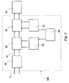
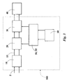
- the devices of Figures 2 and 3 are distinguished with respect to the basic architecture of Figure 1 in so far as they use a microcontroller 60 for controlling the driving blocks 50 and 55 of the power-factor correction stage 20 and of the output stage 30, respectively.
- the diagram of Figure 3 highlights the possibility of merging the blocks 50 and 55 into a single block.
- document US-B-6 501 235 illustrates a device for recognition of lamps based upon information obtained from the filaments of the lamps.
- This device presents limits in recognizing lamps that are different but have similar characteristics in the filaments: the device can thus be adopted only for the recognition of lamps that have filaments with marked differences, given also the variability of these characteristics with temperature.
- the object of the present invention is thus to provide a fully satisfactory response to those needs.
- the solution described herein relates to a process for recognizing the supply power of discharge lamps, in which the lamps are supplied by making a correction of the power factor on the basis of a given conduction time.
- the process moreover comprises the steps of:
- the present invention relates to devices for the power supplying of discharge lamps, which, thanks to the use of a microcontroller, are able to automatically recognize the lamp that is connected thereto, correctly establishing and setting the operating parameters for the aforesaid lamp.
- Each lamp is characterized by different operating parameters that uniquely distinguish it from the other lamps. It is possible to correctly drive lamps of different types and powers with a single power-supply device by measuring the operating parameters of a lamp and sizing the output of the power-supply device on the basis of the values assumed by these parameters.
- the calculation of the lamp power is not made, as generally occurs in the known art, by multiplying the lamp voltage by the lamp current.
- Figure 4 refers specifically to the block 20.
- the microcontroller is set in conditions of directly deriving the lamp power by reading the conduction time Ton of an electronic switch Q1 comprised in the power-factor correction block 20.
- the block 20 comprises a network substantially resembling a low-pass filter LC comprising an inductor L and a capacitor C, with an interposed diode D.
- the electronic switch Q1 by closing itself, short-circuits the point of connection between the inductor L and the diode D to ground.
- the power-factor correction block 20 basically comprises a boost converter that works in transition mode at a variable frequency, with the conduction time of the electronic switch Q1 fixed and designated by Ton. Meanwhile the output block 30 transforms the d.c. voltage into high-frequency a.c. voltage and comprises two electronic switches in half-bridge configuration that work in zero-voltage switching mode.
- the conduction time Ton in the operating mode of the power-factor correction block 20, i.e. in the transition mode, is constant and is directly proportional to the lamp power.
- the power-factor correction block 20 is in fact controlled by the block 50 (in a way known per se) so as to maintain the voltage at output on the load 40, i.e. on the lamp, constant. For this purpose it adapts the conduction time Ton proportionally to the power absorbed, as emerges from the relation given below.
- Ton 2 ⁇ L ⁇ P 0 V inrms 2
- the time Ton is directly proportional to the power of the load 40, which in this case is represented by the lamp itself.
- the advantage of using this solution consists in recognizing the lamp power without making measurements of voltage on the lamp and without resorting to complex multiplications on the microcontroller 60.
- a.c. input voltage is recognized in order to be able to identify the factor V inrms in the preceding relation, and in a step 202 the power supply is initialized.
- the microcontroller 60 carries out a check on the input voltage as soon as the power supply is supplied.
- a step 204 it is verified whether the lamp has already been recognized previously or not.
- an identification code is stored on the EEPROM of the microcontroller 60, said code enabling the microcontroller itself to set the correct parameters of the lamp each time the lamp 40 is turned back on.
- the microcontroller 60 fixes the initial parameters (current/voltage and time for pre-heating of the cathodes, striking sequence, etc.), and makes a first selection on the type of lamp. This selection implies a measurement of resistance of the filaments in the lamps.
- step 206 in which all the subsequent steps of power supply of the lamp are carried out with the values of the parameters already previously set.
- step 208 in which the family to which the lamp to be supplied belongs is recognized.
- the lamp is turned on, monitoring the voltage at striking. Once this datum is acquired, the microcontroller 60 recognizes the lamp that is connected and fixes a current therefor. In this way, the lamp will absorb a clearly determined power.
- the reference number 210 designates the step in which the power-factor correction block 20 is activated, whilst in a step 212 the lamp is pre-heated (according to criteria known per se). In a subsequent step 214, the lamp is started, and in a step 216 the striking voltage of the lamp is monitored by the microcontroller 60, which is able to make a first detailed recognition of the lamp.
- the microcontroller fixes the current of the lamp and the conduction time Ton for the power-factor correction block 20, setting them at the values corresponding to the recognized lamp.
- a step 220 the microcontroller verifies whether the conduction time Ton measured on the switch Q1 is consistent with the conduction time Ton estimated for the type of recognized lamp.
- the microcontroller 60 carries out a check on the conduction time of the switch Q1 of the block 20, verifying, in effect, the power absorbed by the load 40 (i.e. the lamp). This verification is necessary to confirm whether, with the current set, the lamp has been recognized correctly.
- step 226 in which the operating parameters are confirmed.
- the process proceeds with a step 222, in which a new recognition of the lamp is made in accordance with the value of the conduction time Ton actually measured.
- the microcontroller fixes the new parameters associated to the recognized lamp. Also in this case, the process proceeds with a step 226, in which the operating parameters are confirmed.
- the recognition of the lamp is then made by associating a reading of the striking voltage of the lamp, with a verification of the conduction time Ton of the switch Q1 in the block 20.
- the microcontroller establishes the parameters for properly driving the lamp in all its operating conditions, adapting also all the protection thresholds.
- the initial conditions will be the ones for the lamp previously recognized, but the microcontroller will always verify that the parameters set correspond to those of the actually connected lamp.
Landscapes
- Circuit Arrangements For Discharge Lamps (AREA)
Abstract
- i) if the estimated conduction time and the measured conduction time are consistent with one another, the control circuit recognizes the power supply as the one corresponding to the first recognition; and
- ii) if the estimated conduction time and the measured conduction time are not consistent with one another, the control circuit recognizes the power supply as the one corresponding to the conduction time measured.
Description
- The present invention relates to techniques that enable recognition of the power of discharge lamps and has been developed with particular attention paid to its possible use in electronic devices designed to supply such lamps.
- Discharge lamps, such as fluorescent lamps and high-intensity discharge lamps (HIDs), are among the most popular in view of their luminous efficiency, their good chromatic yield and their long life as compared to incandescent lamps.
- The above types of lamps are not able to operate if connected directly to the power supply network. For proper operation, said lamps require the use of intermediate devices, such as, for example, electronic power supplies, which are able to perform the following functions:
- supplying the voltage for initial starting;
- stabilizing the current of the lamp; and
- correcting the operating parameters of the lamp (voltage and current).
- The devices for the power supplying of discharge lamps are divided into two types: electromagnetic and electronic. The electronic devices offer, as compared to magnetic ones, the following advantages:
- high efficiency;
- long life of the tubes;
- better control of the power; and
- smaller dimensions.
- With the advent of microcontrollers in electronic circuits, the devices for the power supplying of said lamps have improved further their performance in terms of precision of the control circuits and of flexibility of design.
- In general, these devices are designed for driving one and the same type of lamp or at the most a set of lamps with a fixed and defined power.
- Some examples of known devices for the power supplying of discharge lamps will now be described with reference to Figures 1, 2, and 3.
- The a.c.
voltage 5, supplied by the supply network, is sent at input to thepower supply device 100. Said device comprises arectifier block 10, and thevoltage 15, at output from theaforesaid rectifier block 10, is sent to a power-factor correction (PFC)block 20, which performs re-phasing of the current absorbed by theload 40 and regulates the voltage at the output block 30 (high-frequency inverter). The power-factor correction block 20 is controlled by adriving block 50, whilst theoutput block 30 is controlled by adriving block 55. In the case illustrated, theload 40 is represented precisely by the discharge lamp. - The devices of Figures 2 and 3 are distinguished with respect to the basic architecture of Figure 1 in so far as they use a
microcontroller 60 for controlling thedriving blocks factor correction stage 20 and of theoutput stage 30, respectively. In particular, the diagram of Figure 3 highlights the possibility of merging theblocks - Individual power-
supply devices 100, or "ballasts", which supply lamps with different powers are today present on the market and are able to drive lamps traversed by one and the same discharge current. In this case, it is sufficient to size the output block 30 (high-frequency inverter) so as to guarantee the current of the lamp designed to ensure the correct power of the lamp during operation in steady-state conditions. - A very different question is the one regarding lamps traversed by different currents. In this case, the
output block 30 will have to "understand" what type of lamp is now connected and adapt its working frequency so as to supply the right current intensity to the lamp. - There exist patents on power-supply devices compatible with different types of lamps.
- For example, document
US-B-6 501 235 , filed in the name of the present Applicant, illustrates a device for recognition of lamps based upon information obtained from the filaments of the lamps. This device presents limits in recognizing lamps that are different but have similar characteristics in the filaments: the device can thus be adopted only for the recognition of lamps that have filaments with marked differences, given also the variability of these characteristics with temperature. - From the foregoing description of the current situation, it may be evinced that there exists the need to define solutions that are able to carry out, in a more satisfactory way, recognition of the discharge lamps in order to correctly supply power to said lamps.
- The object of the present invention is thus to provide a fully satisfactory response to those needs.
- According to the present invention, that object is achieved by means of a process having the features set forth in the claims that follow. The present invention relates also to a corresponding device.
- The claims are an integral part of the disclosure of the invention provided herein.
- In the currently preferred embodiment, the solution described herein relates to a process for recognizing the supply power of discharge lamps, in which the lamps are supplied by making a correction of the power factor on the basis of a given conduction time. The process moreover comprises the steps of:
- starting the lamp, making a first recognition of the power supply of the lamp as a function of the striking voltage,
- estimating the conduction time for the correction of the power factor as a function of the power supply corresponding to the first recognition,
- measuring the conduction time for the correction of the power factor effectively applied to the lamp,
- comparing the estimated conduction time for the correction of the power factor with the measured one, and
- ,i) if the estimated conduction time for the correction of the power factor and the measured conduction time for the correction of the power factor are consistent with one another, recognizing the power supply as corresponding to the first recognition;
- ,ii) if the estimated conduction time for the correction of the power factor and the measured conduction time for the correction of the power factor are not consistent with one another, recognizing the power supply as corresponding to the conduction time measured.
- The invention will now be described, by way of non-limiting example, with reference to the figures of the annexed drawings, in which:
- Figures 1, 2, and 3 have already been described previously;
- Figure 4 illustrates an example of embodiment of a block that may be inserted in the architectures of Figures 1-3 to achieve the solution described herein; and
- Figure 5 is a flowchart of the solution described herein.
- The present invention relates to devices for the power supplying of discharge lamps, which, thanks to the use of a microcontroller, are able to automatically recognize the lamp that is connected thereto, correctly establishing and setting the operating parameters for the aforesaid lamp.
- By "operating parameters" of a discharge lamp are meant, in general:
- current and/or voltage for pre-heating the cathodes;
- time for pre-heating the cathodes;
- striking voltage of the lamp; and
- current and/or voltage of the lamp in steady-state conditions.
- The use of the phrase "in general" is intended to take into account the fact that not necessarily all discharge lamps, to correctly operate, need to detect and control all the aforesaid parameters.
- Each lamp is characterized by different operating parameters that uniquely distinguish it from the other lamps. It is possible to correctly drive lamps of different types and powers with a single power-supply device by measuring the operating parameters of a lamp and sizing the output of the power-supply device on the basis of the values assumed by these parameters.
- The solution described herein enables the recognition and the proper power supply of lamps that are of different powers and that are traversed by different currents.
- The calculation of the lamp power is not made, as generally occurs in the known art, by multiplying the lamp voltage by the lamp current.
- The solution described herein may be used in the field of known per se architectures, such as the ones represented in Figures 2 and 3, which envisage the use of a
microcontroller 60. - The sequel of the present description will consequently make reference to the architecture represented in Figure 3, comprising at input the
rectifier block 10, the power-factor correction block 20 and theoutput block 30. These blocks are managed by themicrocontroller 60, which drives the drivingblock 50 so as to manage the blocks present in the power-supply device 100. - Figure 4 refers specifically to the
block 20. Here it may be seen that, via aline 16, the microcontroller is set in conditions of directly deriving the lamp power by reading the conduction time Ton of an electronic switch Q1 comprised in the power-factor correction block 20. Specifically theblock 20 comprises a network substantially resembling a low-pass filter LC comprising an inductor L and a capacitor C, with an interposed diode D. The electronic switch Q1, by closing itself, short-circuits the point of connection between the inductor L and the diode D to ground. - The power-
factor correction block 20 basically comprises a boost converter that works in transition mode at a variable frequency, with the conduction time of the electronic switch Q1 fixed and designated by Ton. Meanwhile theoutput block 30 transforms the d.c. voltage into high-frequency a.c. voltage and comprises two electronic switches in half-bridge configuration that work in zero-voltage switching mode. - The conduction time Ton, in the operating mode of the power-
factor correction block 20, i.e. in the transition mode, is constant and is directly proportional to the lamp power. The power-factor correction block 20 is in fact controlled by the block 50 (in a way known per se) so as to maintain the voltage at output on theload 40, i.e. on the lamp, constant. For this purpose it adapts the conduction time Ton proportionally to the power absorbed, as emerges from the relation given below. - The relation, which links the power absorbed by the
load 40 to the conduction time Ton of the electronic switch Q1 of the power-factor correction block 20, is:
where: - Ton is the conduction time of the electronic switch Q1;
- L is the inductance of the power-
factor correction block 20; - Vinrms is the r.m.s. value of the a.c.
voltage 15 at input to theblock 20; and - P0 is the power applied to the
load 40. - From the foregoing relation it may be noted that the time Ton is directly proportional to the power of the
load 40, which in this case is represented by the lamp itself. - The advantage of using this solution consists in recognizing the lamp power without making measurements of voltage on the lamp and without resorting to complex multiplications on the
microcontroller 60. - The principle of operation will now be described with reference to the flowchart of Figure 5.
- In a
step 200 the a.c. input voltage is recognized in order to be able to identify the factor Vinrms in the preceding relation, and in a step 202 the power supply is initialized. Themicrocontroller 60 carries out a check on the input voltage as soon as the power supply is supplied. In astep 204 it is verified whether the lamp has already been recognized previously or not. - Once the
lamp 40 has been recognized, an identification code is stored on the EEPROM of themicrocontroller 60, said code enabling the microcontroller itself to set the correct parameters of the lamp each time thelamp 40 is turned back on. - Having made this check, the
microcontroller 60 fixes the initial parameters (current/voltage and time for pre-heating of the cathodes, striking sequence, etc.), and makes a first selection on the type of lamp. This selection implies a measurement of resistance of the filaments in the lamps. - If the lamp has already been recognized (output YES from step 204), the process proceeds with a
step 206, in which all the subsequent steps of power supply of the lamp are carried out with the values of the parameters already previously set. - If the lamp has not yet been recognized (output NO from step 204), the process proceeds with a
step 208, in which the family to which the lamp to be supplied belongs is recognized. - In particular, there exist families of lamps with high-resistance cathodes and families of lamps with low-resistance cathodes. By measuring the resistance of the cathodes it is possible to distinguish to which of the two families a given lamp belongs. This distinction is necessary in so far as lamps belonging to different families work with totally different parameters also in the initial step.
- With these initial conditions, the lamp is turned on, monitoring the voltage at striking. Once this datum is acquired, the
microcontroller 60 recognizes the lamp that is connected and fixes a current therefor. In this way, the lamp will absorb a clearly determined power. - In particular, in the flowchart of Figure 5, the
reference number 210 designates the step in which the power-factor correction block 20 is activated, whilst in astep 212 the lamp is pre-heated (according to criteria known per se). In asubsequent step 214, the lamp is started, and in astep 216 the striking voltage of the lamp is monitored by themicrocontroller 60, which is able to make a first detailed recognition of the lamp. - Next, in a
step 218, the microcontroller fixes the current of the lamp and the conduction time Ton for the power-factor correction block 20, setting them at the values corresponding to the recognized lamp. - In a
step 220 the microcontroller verifies whether the conduction time Ton measured on the switch Q1 is consistent with the conduction time Ton estimated for the type of recognized lamp. Basically, themicrocontroller 60 carries out a check on the conduction time of the switch Q1 of theblock 20, verifying, in effect, the power absorbed by the load 40 (i.e. the lamp). This verification is necessary to confirm whether, with the current set, the lamp has been recognized correctly. - If it has, the process proceeds with a
step 226, in which the operating parameters are confirmed. - Otherwise, the process proceeds with a
step 222, in which a new recognition of the lamp is made in accordance with the value of the conduction time Ton actually measured. Next, in astep 224, the microcontroller fixes the new parameters associated to the recognized lamp. Also in this case, the process proceeds with astep 226, in which the operating parameters are confirmed. - The recognition of the lamp is then made by associating a reading of the striking voltage of the lamp, with a verification of the conduction time Ton of the switch Q1 in the
block 20. - Once the lamp has been uniquely identified, the microcontroller establishes the parameters for properly driving the lamp in all its operating conditions, adapting also all the protection thresholds.
- The next time the lamp is turned on, the initial conditions will be the ones for the lamp previously recognized, but the microcontroller will always verify that the parameters set correspond to those of the actually connected lamp.
- Consequently, without prejudice to the principle of the invention, the details of construction and the embodiments may vary, even significantly, with respect to what is described and illustrated herein purely by way of non-limiting example, without thereby departing from the scope of the invention, as defined by the annexed claims.
Claims (8)
- A process for recognizing the power supply of discharge lamps (40), in which said lamps (40) are supplied (30) by making a correction of the power factor (20) on the basis of a given conduction time (Ton), the process comprising the steps of:- starting (214) the lamp (40), making (216) a first recognition of the power supply of the lamp (40) as a function of the striking potential;- estimating (60) the conduction time (Ton) for said correction of the power factor (20) as a function of the power supply corresponding to said first recognition;- measuring (Q1) the conduction time (Ton) for said correction of the power factor (20) effectively applied to said lamp (40);- comparing (220) the estimated (60) conduction time (Ton) for said correction of the power factor (20) with the measured (Q1) one; and- i) if said estimated (60) conduction time (Ton) for said correction of the power factor (20) and said measured (Q1) one are consistent with one another, recognizing (226) said power supply as corresponding to said first recognition;- ii) if said estimated (60) conduction time (Ton) for said correction of the power factor (20) and said measured (Q1) one are not consistent with one another, recognizing (226) said power supply as corresponding to said conduction time measured (Q1).
- The process according to Claim 1, characterized in that said step of estimating (60) the conduction time (Ton) involves application of the relation:

where:- P0 is said power supply corresponding to said first recognition;- Ton is said conduction time;- L is a value of inductance associated to the correction (20) of the power factor; and- Vinrms is the r.m.s. value of the a.c. voltage at input to said correction (20) of the power factor. - The process according to Claim 1 or Claim 2, characterized in that it also includes the step of regulating at least one of the following parameters of the lamp (40):- current and/or voltage for pre-heating of the cathodes;- time for pre-heating the cathodes;- striking voltage; and- current and/or voltage of the lamp in steady-state conditions.
- A device for recognizing the power supply of discharge lamps (40), comprising:- an output block for the power supplying of the lamp (40);- a power-factor correction block (20) for correcting the power factor on the basis of a given conduction time (Ton); and- a control circuit (60), which is sensitive to the supply voltage of the lamp (40) for detecting, at starting of the lamp (40), the striking voltage and making (216) a first recognition of the power supply of the lamp (40) as a function of the striking voltage, likewise estimating the conduction time (Ton) for said correction of the power factor as a function of the power supply corresponding to said first recognition;said control circuit (60) being configured for measuring (Q1) the conduction time (Ton) for said correction of the power factor effectively applied (20) to said lamp (40) and comparing (220) the estimated (60) conduction time (Ton) for said correction of the power factor with the measured (Q1) one so that- i) if said estimated (60) conduction time (Ton) for said correction of the power factor (20) and said measured (Q1) one are consistent with one another, said control circuit (60) recognizes (226) said power supply as corresponding to said first recognition;- ii) if said estimated (60) conduction time (Ton) for said correction of the power factor (20) and said measured (Q1) one are not consistent with one another, said control circuit (60) recognizes (226) said power supply as corresponding to said conduction time measured (Q1).
- The device according to Claim 4, characterized in that said control circuit (60) is configured for estimating (60) said conduction time (Ton) with the relation:

where:- P0 is said power supply corresponding to said first recognition;- Ton is said conduction time;- L is a value of inductance associated to the correction (20) of the power factor; and- Vinrms is the r.m.s. value of the a.c. voltage at input to said correction (20) of the power factor. - The device according to Claim 4 or Claim 5, characterized in that said control circuit (60) is configured for regulating at least one of the following parameters of the lamp (40):- current and/or voltage for pre-heating of the cathodes;- time for pre-heating the cathodes;- striking voltage; and- current and/or voltage of the lamp in steady-state conditions.
- The device according to Claim 6, characterized in that said control circuit is a microcontroller (60).
- The device according to any one of Claims 4 to 7, characterized in that said correction block (20) for correcting the power factor comprises a boost converter that works in transition mode at a variable frequency.
Priority Applications (2)
| Application Number | Priority Date | Filing Date | Title |
|---|---|---|---|
| DE602006013616T DE602006013616D1 (en) | 2006-07-20 | 2006-07-20 | Device and method for detecting the supply power of a discharge lamp |
| EP06425504A EP1881745B1 (en) | 2006-07-20 | 2006-07-20 | Process for recognizing the supply power of discharge lamps and related device |
Applications Claiming Priority (1)
| Application Number | Priority Date | Filing Date | Title |
|---|---|---|---|
| EP06425504A EP1881745B1 (en) | 2006-07-20 | 2006-07-20 | Process for recognizing the supply power of discharge lamps and related device |
Publications (2)
| Publication Number | Publication Date |
|---|---|
| EP1881745A1 true EP1881745A1 (en) | 2008-01-23 |
| EP1881745B1 EP1881745B1 (en) | 2010-04-14 |
Family
ID=37492621
Family Applications (1)
| Application Number | Title | Priority Date | Filing Date |
|---|---|---|---|
| EP06425504A Not-in-force EP1881745B1 (en) | 2006-07-20 | 2006-07-20 | Process for recognizing the supply power of discharge lamps and related device |
Country Status (2)
| Country | Link |
|---|---|
| EP (1) | EP1881745B1 (en) |
| DE (1) | DE602006013616D1 (en) |
Cited By (4)
| Publication number | Priority date | Publication date | Assignee | Title |
|---|---|---|---|---|
| DE102008027029A1 (en) | 2008-06-06 | 2009-12-10 | Tridonicatco Gmbh & Co. Kg | Lamp type detection by power factor correction circuit |
| DE102008047440A1 (en) * | 2008-09-16 | 2010-03-25 | Tridonicatco Gmbh & Co. Kg | Determination of the type of bulb or the topology of several bulbs |
| WO2012042412A3 (en) * | 2010-09-28 | 2012-06-14 | Koninklijke Philips Electronics N.V. | Device and method for automatically detecting installed lamp type |
| DE102012014308A1 (en) | 2012-04-13 | 2013-10-17 | Tridonic Gmbh & Co. Kg | Operating device for a lamp and method for operating a control gear |
Citations (5)
| Publication number | Priority date | Publication date | Assignee | Title |
|---|---|---|---|---|
| EP0413991A1 (en) * | 1989-07-28 | 1991-02-27 | Toshiba Lighting & Technology Corporation | Discharge lamp lighting apparatus for driving discharge lamp according to rating thereof |
| US6501235B2 (en) | 2001-02-27 | 2002-12-31 | Stmicroelectronics Inc. | Microcontrolled ballast compatible with different types of gas discharge lamps and associated methods |
| EP1317052A2 (en) * | 2001-11-29 | 2003-06-04 | Sanken Electric Co., Ltd. | Switching power supply |
| US20030160578A1 (en) | 2002-02-22 | 2003-08-28 | Mitsubishi Denki Kabushiki Kaisha | Apparatus for lighting a discharge lamp at electric characteristics appropriate to a type of the discharge lamp |
| EP1580639A1 (en) * | 2004-03-22 | 2005-09-28 | STMicroelectronics S.r.l. | Transition mode power factor correction device in switching power supplies |
-
2006
- 2006-07-20 DE DE602006013616T patent/DE602006013616D1/en active Active
- 2006-07-20 EP EP06425504A patent/EP1881745B1/en not_active Not-in-force
Patent Citations (5)
| Publication number | Priority date | Publication date | Assignee | Title |
|---|---|---|---|---|
| EP0413991A1 (en) * | 1989-07-28 | 1991-02-27 | Toshiba Lighting & Technology Corporation | Discharge lamp lighting apparatus for driving discharge lamp according to rating thereof |
| US6501235B2 (en) | 2001-02-27 | 2002-12-31 | Stmicroelectronics Inc. | Microcontrolled ballast compatible with different types of gas discharge lamps and associated methods |
| EP1317052A2 (en) * | 2001-11-29 | 2003-06-04 | Sanken Electric Co., Ltd. | Switching power supply |
| US20030160578A1 (en) | 2002-02-22 | 2003-08-28 | Mitsubishi Denki Kabushiki Kaisha | Apparatus for lighting a discharge lamp at electric characteristics appropriate to a type of the discharge lamp |
| EP1580639A1 (en) * | 2004-03-22 | 2005-09-28 | STMicroelectronics S.r.l. | Transition mode power factor correction device in switching power supplies |
Non-Patent Citations (2)
| Title |
|---|
| SPANGLER J J ET AL: "A comparison between hysteretic and fixed frequency boost converters used for power factor correction", PROCEEDINGS OF THE ANNUAL APPLIED POWER ELECTRONICS CONFERENCE AND EXPOSITION (APEC). SAN DIEGO, MAR. 7 - 11, 1993, NEW YORK, IEEE, US, vol. CONF. 8, 7 March 1993 (1993-03-07), pages 281 - 286, XP010111212, ISBN: 0-7803-0983-9 * |
| SPANGLER JJ ET AL.: "A comparison between hysteretic end fixed frequency boost converters used for power factor correction", PROCEEDINGS OF THE ANNUAL APPLIED POWER ELECTRONICS CONFERENCE AND EXPOSITION (APEC, 7 March 1993 (1993-03-07) |
Cited By (10)
| Publication number | Priority date | Publication date | Assignee | Title |
|---|---|---|---|---|
| DE102008027029A1 (en) | 2008-06-06 | 2009-12-10 | Tridonicatco Gmbh & Co. Kg | Lamp type detection by power factor correction circuit |
| WO2009146934A3 (en) * | 2008-06-06 | 2010-03-04 | Tridonicatco Gmbh & Co. Kg | Lamp type detection by means of power factor correction circuit |
| CN102067734A (en) * | 2008-06-06 | 2011-05-18 | 赤多尼科两合股份有限公司 | Lamp type identification by means of power factor correction circuit |
| CN102067734B (en) * | 2008-06-06 | 2014-08-13 | 赤多尼科两合股份有限公司 | Lamp type identification by means of power factor correction circuit |
| AT518059A5 (en) * | 2008-06-06 | 2017-07-15 | Tridonic Gmbh & Co Kg | LAMP TYPE IDENTIFICATION BY POWER FACTOR CORRECTION |
| AT518059B1 (en) * | 2008-06-06 | 2017-07-15 | Tridonic Gmbh & Co Kg | LAMP TYPE IDENTIFICATION BY POWER FACTOR CORRECTION |
| DE102008047440A1 (en) * | 2008-09-16 | 2010-03-25 | Tridonicatco Gmbh & Co. Kg | Determination of the type of bulb or the topology of several bulbs |
| WO2012042412A3 (en) * | 2010-09-28 | 2012-06-14 | Koninklijke Philips Electronics N.V. | Device and method for automatically detecting installed lamp type |
| DE102012014308A1 (en) | 2012-04-13 | 2013-10-17 | Tridonic Gmbh & Co. Kg | Operating device for a lamp and method for operating a control gear |
| WO2013152373A1 (en) | 2012-04-13 | 2013-10-17 | Tridonic Gmbh & Co. Kg | Operating device for an illuminant and method for operating an operating device |
Also Published As
| Publication number | Publication date |
|---|---|
| DE602006013616D1 (en) | 2010-05-27 |
| EP1881745B1 (en) | 2010-04-14 |
Similar Documents
| Publication | Publication Date | Title |
|---|---|---|
| EP2838321B1 (en) | Led lamp and lighting device including led lamp | |
| AU761194B2 (en) | Electronic ballast for at least one low-pressure discharge lamp | |
| JP5576638B2 (en) | Lighting device and headlight lighting device, headlight, vehicle using the same | |
| JP5266594B1 (en) | LED lamp, lighting device including the LED lamp, and LED lamp current control method | |
| CN102396295B (en) | LED power regulation by means of LED current average value and bidirectional counter | |
| JP2005534277A (en) | Ballast control circuit with power factor correction on a single chip | |
| TW200529704A (en) | Full digital dimming ballast for a fluorescent lamp | |
| CN102291870A (en) | Lighting device, lamp, lighting circuit, and lighting apparatus | |
| WO2009154180A1 (en) | Illumination lighting device, illuminating device, and illuminating system | |
| CN101652012A (en) | High pressure discharge lamp lighting device and luminaire | |
| CN102067734B (en) | Lamp type identification by means of power factor correction circuit | |
| EP2452544B1 (en) | Fluorescent ballast with inherent end-of-life protection | |
| CN102084725B (en) | Method for detecting the type of a gas discharge lamp connected to an operational device | |
| EP1881745B1 (en) | Process for recognizing the supply power of discharge lamps and related device | |
| US20130162143A1 (en) | Lamp control system, lamp power-saving system and method therefor | |
| JP5122882B2 (en) | Lighting device | |
| CN101982021A (en) | Detection of the type of an HID lamp by a multi-lamp operating device and lighting system | |
| CN101682966B (en) | Error detection in an operating device of a lighting device | |
| CN102017809B (en) | Method and device for operating at least one discharge lamp | |
| JP2018508104A (en) | LED tube lamp | |
| CN1750731B (en) | Electronic ballast having a pump circuit for a discharge lamp having preheatable electrodes | |
| JP2009289664A (en) | Lighting device for discharge lamp, and illumination apparatus | |
| JP4441108B2 (en) | Discharge lamp lighting device | |
| JP4948496B2 (en) | Discharge lamp lighting device and lighting device | |
| CN202857113U (en) | Electronic ballast and method for driving at least one discharge lamp |
Legal Events
| Date | Code | Title | Description |
|---|---|---|---|
| PUAI | Public reference made under article 153(3) epc to a published international application that has entered the european phase |
Free format text: ORIGINAL CODE: 0009012 |
|
| AK | Designated contracting states |
Kind code of ref document: A1 Designated state(s): AT BE BG CH CY CZ DE DK EE ES FI FR GB GR HU IE IS IT LI LT LU LV MC NL PL PT RO SE SI SK TR |
|
| AX | Request for extension of the european patent |
Extension state: AL BA HR MK YU |
|
| 17P | Request for examination filed |
Effective date: 20080317 |
|
| 17Q | First examination report despatched |
Effective date: 20080422 |
|
| AKX | Designation fees paid |
Designated state(s): DE FR GB IT |
|
| GRAP | Despatch of communication of intention to grant a patent |
Free format text: ORIGINAL CODE: EPIDOSNIGR1 |
|
| RTI1 | Title (correction) |
Free format text: PROCESS FOR RECOGNIZING THE SUPPLY POWER OF DISCHARGE LAMPS AND RELATED DEVICE |
|
| GRAS | Grant fee paid |
Free format text: ORIGINAL CODE: EPIDOSNIGR3 |
|
| GRAA | (expected) grant |
Free format text: ORIGINAL CODE: 0009210 |
|
| RAP1 | Party data changed (applicant data changed or rights of an application transferred) |
Owner name: STMICROELECTRONICS SRL |
|
| AK | Designated contracting states |
Kind code of ref document: B1 Designated state(s): DE FR GB IT |
|
| REG | Reference to a national code |
Ref country code: GB Ref legal event code: FG4D |
|
| REF | Corresponds to: |
Ref document number: 602006013616 Country of ref document: DE Date of ref document: 20100527 Kind code of ref document: P |
|
| PLBE | No opposition filed within time limit |
Free format text: ORIGINAL CODE: 0009261 |
|
| STAA | Information on the status of an ep patent application or granted ep patent |
Free format text: STATUS: NO OPPOSITION FILED WITHIN TIME LIMIT |
|
| 26N | No opposition filed |
Effective date: 20110117 |
|
| GBPC | Gb: european patent ceased through non-payment of renewal fee |
Effective date: 20100720 |
|
| REG | Reference to a national code |
Ref country code: FR Ref legal event code: ST Effective date: 20110331 |
|
| PG25 | Lapsed in a contracting state [announced via postgrant information from national office to epo] |
Ref country code: FR Free format text: LAPSE BECAUSE OF NON-PAYMENT OF DUE FEES Effective date: 20100802 |
|
| PG25 | Lapsed in a contracting state [announced via postgrant information from national office to epo] |
Ref country code: GB Free format text: LAPSE BECAUSE OF NON-PAYMENT OF DUE FEES Effective date: 20100720 |
|
| PGFP | Annual fee paid to national office [announced via postgrant information from national office to epo] |
Ref country code: IT Payment date: 20120625 Year of fee payment: 7 |
|
| PGFP | Annual fee paid to national office [announced via postgrant information from national office to epo] |
Ref country code: DE Payment date: 20130621 Year of fee payment: 8 |
|
| PG25 | Lapsed in a contracting state [announced via postgrant information from national office to epo] |
Ref country code: IT Free format text: LAPSE BECAUSE OF NON-PAYMENT OF DUE FEES Effective date: 20130720 |
|
| REG | Reference to a national code |
Ref country code: DE Ref legal event code: R119 Ref document number: 602006013616 Country of ref document: DE |
|
| REG | Reference to a national code |
Ref country code: DE Ref legal event code: R119 Ref document number: 602006013616 Country of ref document: DE Effective date: 20150203 |
|
| PG25 | Lapsed in a contracting state [announced via postgrant information from national office to epo] |
Ref country code: DE Free format text: LAPSE BECAUSE OF NON-PAYMENT OF DUE FEES Effective date: 20150203 |