EP1881730A1 - Electronic apparatus - Google Patents
Electronic apparatus Download PDFInfo
- Publication number
- EP1881730A1 EP1881730A1 EP06732385A EP06732385A EP1881730A1 EP 1881730 A1 EP1881730 A1 EP 1881730A1 EP 06732385 A EP06732385 A EP 06732385A EP 06732385 A EP06732385 A EP 06732385A EP 1881730 A1 EP1881730 A1 EP 1881730A1
- Authority
- EP
- European Patent Office
- Prior art keywords
- casing
- display part
- electronic device
- sound guide
- speaker
- Prior art date
- Legal status (The legal status is an assumption and is not a legal conclusion. Google has not performed a legal analysis and makes no representation as to the accuracy of the status listed.)
- Withdrawn
Links
Images


Classifications
-
- H—ELECTRICITY
- H04—ELECTRIC COMMUNICATION TECHNIQUE
- H04R—LOUDSPEAKERS, MICROPHONES, GRAMOPHONE PICK-UPS OR LIKE ACOUSTIC ELECTROMECHANICAL TRANSDUCERS; ELECTRIC HEARING AIDS; PUBLIC ADDRESS SYSTEMS
- H04R1/00—Details of transducers, loudspeakers or microphones
- H04R1/20—Arrangements for obtaining desired frequency or directional characteristics
- H04R1/32—Arrangements for obtaining desired frequency or directional characteristics for obtaining desired directional characteristic only
- H04R1/34—Arrangements for obtaining desired frequency or directional characteristics for obtaining desired directional characteristic only by using a single transducer with sound reflecting, diffracting, directing or guiding means
- H04R1/345—Arrangements for obtaining desired frequency or directional characteristics for obtaining desired directional characteristic only by using a single transducer with sound reflecting, diffracting, directing or guiding means for loudspeakers
-
- H—ELECTRICITY
- H04—ELECTRIC COMMUNICATION TECHNIQUE
- H04N—PICTORIAL COMMUNICATION, e.g. TELEVISION
- H04N5/00—Details of television systems
- H04N5/64—Constructional details of receivers, e.g. cabinets or dust covers
-
- H—ELECTRICITY
- H04—ELECTRIC COMMUNICATION TECHNIQUE
- H04N—PICTORIAL COMMUNICATION, e.g. TELEVISION
- H04N5/00—Details of television systems
- H04N5/64—Constructional details of receivers, e.g. cabinets or dust covers
- H04N5/642—Disposition of sound reproducers
-
- H—ELECTRICITY
- H04—ELECTRIC COMMUNICATION TECHNIQUE
- H04R—LOUDSPEAKERS, MICROPHONES, GRAMOPHONE PICK-UPS OR LIKE ACOUSTIC ELECTROMECHANICAL TRANSDUCERS; ELECTRIC HEARING AIDS; PUBLIC ADDRESS SYSTEMS
- H04R31/00—Apparatus or processes specially adapted for the manufacture of transducers or diaphragms therefor
- H04R31/006—Interconnection of transducer parts
-
- H—ELECTRICITY
- H04—ELECTRIC COMMUNICATION TECHNIQUE
- H04R—LOUDSPEAKERS, MICROPHONES, GRAMOPHONE PICK-UPS OR LIKE ACOUSTIC ELECTROMECHANICAL TRANSDUCERS; ELECTRIC HEARING AIDS; PUBLIC ADDRESS SYSTEMS
- H04R2499/00—Aspects covered by H04R or H04S not otherwise provided for in their subgroups
- H04R2499/10—General applications
- H04R2499/13—Acoustic transducers and sound field adaptation in vehicles
-
- H—ELECTRICITY
- H04—ELECTRIC COMMUNICATION TECHNIQUE
- H04R—LOUDSPEAKERS, MICROPHONES, GRAMOPHONE PICK-UPS OR LIKE ACOUSTIC ELECTROMECHANICAL TRANSDUCERS; ELECTRIC HEARING AIDS; PUBLIC ADDRESS SYSTEMS
- H04R2499/00—Aspects covered by H04R or H04S not otherwise provided for in their subgroups
- H04R2499/10—General applications
- H04R2499/15—Transducers incorporated in visual displaying devices, e.g. televisions, computer displays, laptops
Definitions
- a speaker such as, for example, a liquid crystal television set and a car navigation system
- the speaker is positioned on an outer side of a liquid crystal display part in a front view, but positioning the speaker on the outer side of the liquid crystal display part causes a problem of an increase in size of the electronic devices.
- the electronic device with an increased size is difficult to dispose in a limited space such as, for example, the interior of an automobile, which makes the electronic device not convenient to use.
- the sound guide channel guiding the sound generated from the speaker to the external part of the casing has to be formed separately and independently, which poses another problem of an increase in the number of assembly processes, manufacturing cost, and weight of the electronic device.
- the sound guide channel has to be bent so as to bypass the liquid crystal display part.
- An invention of claim 1 includes: a casing as an outer frame; a display part provided inside the casing to display predetermined information; a speaker provided on a rear side of the display part, inside the casing so as to partly protrude from the display part; and a sound guide part extending linearly from a front face side of the speaker to guide sound generated from the speaker to an external part of the casing.
- the speaker is provided on the rear side of the display part, inside the casing so as to partly protrude from the display part, and the sound guide part guiding the sound generated from the speaker to the external part of the casing extends linearly from the front face side of the speaker, and thus the sound guide part is not bent. Therefore, even high-frequency sound generated from the speaker can be outputted to the external part of the casing without any deterioration in sound quality.
- the speaker since the speaker is provided on the rear side of the display part, inside the casing so as to partly protrude from the display part, the speaker does not have to be disposed on the front face of the casing which is on the outer side of the display part, as in conventional electronic devices. This can make the electronic device compact, resulting in weight reduction of the electronic device. As a result, the electronic device can be easily disposed in a limited space such as, for example, the interior of an automobile.
- the sound guide part since the sound guide part also has the display part fixing function of fixing the display part, it is possible to form a sound guide channel by using an existing constituent member basically required for the electronic device. This can prevent an increase in the number of assembly processes and weight of the electronic device, as contrast to a case where the sound guide part is formed by using an independent member different from a fixing part fixing the display part. Further, by the output of sound from the speaker, not only the casing can be resonated but also the display part can be resonated via the sound guide channel, which can improve quality of sound outputted from the speaker.
- the sound guide part since the sound guide part also has the speaker fixing function of fixing the speaker, it is possible to form a sound guide channel by using an existing constituent member basically required for the electronic device. This can prevent an increase in the number of assembly processes and weight of the electronic device, as contrast to a case where the sound guide part is formed by using a different independent member fixing the speaker.
- the sound guide part is made of a material not transmitting light, light from the display part can be prevented from transmitting through the sound guide part and leaking to the external part of the casing, even in the structure where especially the sound guide part also has the display part fixing function of fixing the display part.
- the electronic device of the present invention is widely applicable to, for example, a liquid crystal television set, a car navigation system, and so on.
- an electronic device 10 includes a box-shaped casing 12 as an outer frame.
- the casing 12 is composed of a casing front portion 12A positioned on a forward (front face) side and a casing rear portion 12B positioned on a backward (rear face) side which are combined with each other.
- Support parts 14 are formed in front of (on a front face side of) the casing front portion 12A, and a touch panel part 16 is disposed behind (on rear face side of) the support parts 14.
- an operation part 18 is provided under the touch panel part 16.
- input buttons 18A and so on necessary for the operation are disposed.
- slit parts 18B forming entrances of later-described sound guide ducts (sound guide parts) 24 are provided respectively.
- a liquid crystal display part (display part) 20 displaying predetermined information is disposed behind (on a rear face side of) the touch panel part 16.
- the liquid crystal display part 20 together with the touch panel part 16 is positioned and fixed inside the casing front portion 12A by claw portions 22 formed on the casing front portion 12A, upper sound guide duct parts 24A constituting the later-described sound guide ducts 24, and the aforesaid support parts 14.
- the sound guide ducts (sound guide parts) 24 guiding sound generated from later-described speakers 28 to the front face of the casing front portion 12A are attached to left and right lower portions of the liquid crystal display part 20 by screws 26, respectively.
- Each of the sound guide ducts 24 is attached to the casing front portion 12A and is formed as a space closed by the upper sound guide duct part 24A positioning and fixing the liquid crystal display part 20 and a lower sound guide part 24B attached to the casing front portion 12A. Therefore, sound generated from the later-described speakers 28 is outputted from the slit parts 18B without leaking to an external part of the casing 12.
- the upper sound guide duct parts 24A and the lower sound guide duct parts 24B are made of a material not transmitting light, such as, for example, black plastic resin.
- each of the speakers 28 is attached by screws 30 to a rear end portion of the upper sound guide duct part 24A and a rear end portion of the lower sound guide duct part 24B.
- each of the sound guide ducts 24 extends linearly from the front face side of the speaker 28 toward the front face side of the casing front portion 12A.
- a front end portion of each of the upper sound guide duct parts 24A and a front end portion of each of the lower sound guide duct parts 24B are connected to the slit part 18B.
- the speakers 28 are provided on the rear side of the liquid crystal display part 20, inside the casing front portion 12A so as to partly protrude downward from the liquid crystal display part 20.
- the sound guide ducts 24 also have a display part fixing function of fixing the liquid crystal display part 20 and also has a speaker fixing function of fixing the speakers 28.
- the speakers 28 are provided on the rear side of the liquid crystal display part 20, inside the casing front portion 12A so as to partly protrude downward from the liquid crystal display part 20, and the sound guide ducts 24 extend linearly from the front face side of the speakers 28 toward the front face side of the casing front portion 12A.
- the sound guide ducts 24 are not bent. Therefore, even high-frequency sound generated from the speakers 28 can be outputted to the external part of the casing 12 without any sound quality deterioration.
- the speakers 28 do not have to be disposed on the front face of the casing 12 which is on the outer side of the liquid crystal display part 20, the electronic device 10 can be made compact, resulting in reduction in weight of the electronic device 10. As a result, the electronic device 10 can be easily disposed even in a limited space such as, for example, the interior of an automobile.
- the sound guide ducts 24 can be formed by using existing constituent members basically necessary for the electronic device 10 especially because the sound guide ducts 24 also have the display part fixing function of fixing the liquid crystal display part 20. This can prevent an increase in the number of assembly processes and weight of the electronic device 10, as contrast to a case where the sound guide ducts are formed by using independent members different from fixing parts fixing the liquid crystal display part 20. Further, since by the output of sound from the speakers 28, not only the casing 12 can be resonated but also the liquid crystal display part 20 can be resonated via the sound guide ducts 24, it is possible to improve quality of sound outputted from the speakers 28.
- the sound guide ducts 24 also have the speaker fixing function of fixing the speakers 28, the sound guide ducts 24 can be formed by using existing constituent members basically necessary for the electronic device 10. This can prevent an increase in the number of assembly processes and weight of the electronic device 10, as contrast to a case where the sound guide parts are formed by using different independent members fixing the speakers 28.
- the sound guide ducts 24 are made of a material not transmitting light (in this embodiment, black plastic resin), light from the liquid crystal display part 20 and the operation part 18 can be prevented from transmitting through the sound guide ducts 24 and leaking to the external part of the casing 12 via the slit parts 18B, even in the structure where especially the sound guide ducts 24 also have the display part fixing function of fixing the liquid crystal display part 20.
Landscapes
- Engineering & Computer Science (AREA)
- Signal Processing (AREA)
- Physics & Mathematics (AREA)
- Acoustics & Sound (AREA)
- Health & Medical Sciences (AREA)
- Otolaryngology (AREA)
- Multimedia (AREA)
- Manufacturing & Machinery (AREA)
- Fittings On The Vehicle Exterior For Carrying Loads, And Devices For Holding Or Mounting Articles (AREA)
- Details Of Audible-Bandwidth Transducers (AREA)
- Devices For Indicating Variable Information By Combining Individual Elements (AREA)
Abstract
Description
- The present invention relates to an electronic device including a speaker.
- Among conventional electronic devices, those including a speaker such as, for example, a liquid crystal television set and a car navigation system have been known. In most of electronic devices of this type, the speaker is positioned on an outer side of a liquid crystal display part in a front view, but positioning the speaker on the outer side of the liquid crystal display part causes a problem of an increase in size of the electronic devices. In particular, the electronic device with an increased size is difficult to dispose in a limited space such as, for example, the interior of an automobile, which makes the electronic device not convenient to use.
- To solve the above problem, there has been proposed an electronic device in which a speaker is disposed on a rear side of a liquid crystal display part (see, a patent document 1 below). In this electronic device, the speaker is disposed on the rear side of the liquid crystal display part, inside a casing, and a sound guide channel guiding sound generated from the speaker to an external part of the casing is separately and independently formed.
[Patent document 1]
Japanese Patent Application Laid-open No. Hei 8-168037 - However, in the above-described electronic device, the sound guide channel guiding the sound generated from the speaker to the external part of the casing has to be formed separately and independently, which poses another problem of an increase in the number of assembly processes, manufacturing cost, and weight of the electronic device. Further, if the speaker is disposed near a center portion of the liquid crystal display part as in conventional electronic devices, the sound guide channel has to be bent so as to bypass the liquid crystal display part. However, it is difficult to output especially high-frequency sound through the bent sound guide channel to the external part of the casing, which also poses another problem of sound quality deterioration.
- Therefore, considering the above-described circumstances, considering the above-described circumstances, it is an object of the present invention to provide an electronic device whose assembly processes, manufacturing cost, and weight can be reduced and whose sound quality can be prevented from deteriorating.
- An invention of claim 1 includes: a casing as an outer frame; a display part provided inside the casing to display predetermined information; a speaker provided on a rear side of the display part, inside the casing so as to partly protrude from the display part; and a sound guide part extending linearly from a front face side of the speaker to guide sound generated from the speaker to an external part of the casing.
- According to an invention of claim 2, in the electronic device of claim 1, the sound guide part also has a display part fixing function of fixing the display part.
- According to an invention of claim 3, in the electronic device of claim 1 or 2, the sound guide part also has a speaker fixing function of fixing the speaker.
- According to an invention of claim 4, in the electronic device of any one of claims 1 to 3, the sound guide part is made of a material not transmitting light.
- According to the invention of claim 1, the speaker is provided on the rear side of the display part, inside the casing so as to partly protrude from the display part, and the sound guide part guiding the sound generated from the speaker to the external part of the casing extends linearly from the front face side of the speaker, and thus the sound guide part is not bent. Therefore, even high-frequency sound generated from the speaker can be outputted to the external part of the casing without any deterioration in sound quality. Further, since the speaker is provided on the rear side of the display part, inside the casing so as to partly protrude from the display part, the speaker does not have to be disposed on the front face of the casing which is on the outer side of the display part, as in conventional electronic devices. This can make the electronic device compact, resulting in weight reduction of the electronic device. As a result, the electronic device can be easily disposed in a limited space such as, for example, the interior of an automobile.
- According to the invention of claim 2, since the sound guide part also has the display part fixing function of fixing the display part, it is possible to form a sound guide channel by using an existing constituent member basically required for the electronic device. This can prevent an increase in the number of assembly processes and weight of the electronic device, as contrast to a case where the sound guide part is formed by using an independent member different from a fixing part fixing the display part. Further, by the output of sound from the speaker, not only the casing can be resonated but also the display part can be resonated via the sound guide channel, which can improve quality of sound outputted from the speaker.
- According to the invention of claim 3, since the sound guide part also has the speaker fixing function of fixing the speaker, it is possible to form a sound guide channel by using an existing constituent member basically required for the electronic device. This can prevent an increase in the number of assembly processes and weight of the electronic device, as contrast to a case where the sound guide part is formed by using a different independent member fixing the speaker.
- According to the invention of claim 4, since the sound guide part is made of a material not transmitting light, light from the display part can be prevented from transmitting through the sound guide part and leaking to the external part of the casing, even in the structure where especially the sound guide part also has the display part fixing function of fixing the display part.
-
- [FIG. 1] A front view of an electronic device according to an embodiment of the present invention.
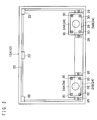
- [FIG. 2] A structural view of the electronic device according to the embodiment of the present invention seen from behind (a rear face side), with a casing rear portion of a casing included in the electronic device being detached.
- [FIG. 3] A vertical cross-sectional view of the electronic device according to the embodiment of the present invention.
-
- 10
- electronic device
- 12
- casing
- 20
- liquid crystal display part (display part)
- 24
- sound guide duct (sound guide part)
- 28
- speaker
- Next, an electronic device according to an embodiment of the present invention will be described with reference to the drawings. It should be noted that the electronic device of the present invention is widely applicable to, for example, a liquid crystal television set, a car navigation system, and so on.
- As shown in FIG. 1 to FIG. 3, an
electronic device 10 includes a box-shaped casing 12 as an outer frame. Thecasing 12 is composed of acasing front portion 12A positioned on a forward (front face) side and a casingrear portion 12B positioned on a backward (rear face) side which are combined with each other.Support parts 14 are formed in front of (on a front face side of) thecasing front portion 12A, and atouch panel part 16 is disposed behind (on rear face side of) thesupport parts 14. Further, in front of (on a front face side of) thecasing 12, anoperation part 18 is provided under thetouch panel part 16. In theoperation part 18,input buttons 18A and so on necessary for the operation are disposed. Further, in left and right portions of theoperation part 18,slit parts 18B forming entrances of later-described sound guide ducts (sound guide parts) 24 are provided respectively. - Further, inside the
casing front portion 12A, a liquid crystal display part (display part) 20 displaying predetermined information is disposed behind (on a rear face side of) thetouch panel part 16. The liquidcrystal display part 20 together with thetouch panel part 16 is positioned and fixed inside thecasing front portion 12A byclaw portions 22 formed on thecasing front portion 12A, upper soundguide duct parts 24A constituting the later-describedsound guide ducts 24, and theaforesaid support parts 14. - Further, as shown in FIG. 2, inside the
casing front portion 12A, the sound guide ducts (sound guide parts) 24 guiding sound generated from later-describedspeakers 28 to the front face of thecasing front portion 12A are attached to left and right lower portions of the liquidcrystal display part 20 byscrews 26, respectively. Each of thesound guide ducts 24 is attached to thecasing front portion 12A and is formed as a space closed by the upper soundguide duct part 24A positioning and fixing the liquidcrystal display part 20 and a lowersound guide part 24B attached to thecasing front portion 12A. Therefore, sound generated from the later-describedspeakers 28 is outputted from theslit parts 18B without leaking to an external part of thecasing 12. Further, the upper soundguide duct parts 24A and the lower soundguide duct parts 24B are made of a material not transmitting light, such as, for example, black plastic resin. - Further, as shown in FIG. 2, each of the
speakers 28 is attached byscrews 30 to a rear end portion of the upper soundguide duct part 24A and a rear end portion of the lower soundguide duct part 24B. In more detail, each of thesound guide ducts 24 extends linearly from the front face side of thespeaker 28 toward the front face side of thecasing front portion 12A. Incidentally, a front end portion of each of the upper sound guideduct parts 24A and a front end portion of each of the lower sound guideduct parts 24B are connected to theslit part 18B. Further, thespeakers 28 are provided on the rear side of the liquidcrystal display part 20, inside the casingfront portion 12A so as to partly protrude downward from the liquidcrystal display part 20. - As described above, in the
electronic device 10 of this embodiment, thesound guide ducts 24 also have a display part fixing function of fixing the liquidcrystal display part 20 and also has a speaker fixing function of fixing thespeakers 28. - Next, the operation of the
electronic device 10 of this embodiment will be described. - As shown in FIG. 1 to FIG. 3, the
speakers 28 are provided on the rear side of the liquidcrystal display part 20, inside the casingfront portion 12A so as to partly protrude downward from the liquidcrystal display part 20, and thesound guide ducts 24 extend linearly from the front face side of thespeakers 28 toward the front face side of thecasing front portion 12A. Thus, thesound guide ducts 24 are not bent. Therefore, even high-frequency sound generated from thespeakers 28 can be outputted to the external part of thecasing 12 without any sound quality deterioration. Further, since thespeakers 28 do not have to be disposed on the front face of thecasing 12 which is on the outer side of the liquidcrystal display part 20, theelectronic device 10 can be made compact, resulting in reduction in weight of theelectronic device 10. As a result, theelectronic device 10 can be easily disposed even in a limited space such as, for example, the interior of an automobile. - The
sound guide ducts 24 can be formed by using existing constituent members basically necessary for theelectronic device 10 especially because thesound guide ducts 24 also have the display part fixing function of fixing the liquidcrystal display part 20. This can prevent an increase in the number of assembly processes and weight of theelectronic device 10, as contrast to a case where the sound guide ducts are formed by using independent members different from fixing parts fixing the liquidcrystal display part 20. Further, since by the output of sound from thespeakers 28, not only thecasing 12 can be resonated but also the liquidcrystal display part 20 can be resonated via thesound guide ducts 24, it is possible to improve quality of sound outputted from thespeakers 28. - Likewise, since the
sound guide ducts 24 also have the speaker fixing function of fixing thespeakers 28, thesound guide ducts 24 can be formed by using existing constituent members basically necessary for theelectronic device 10. This can prevent an increase in the number of assembly processes and weight of theelectronic device 10, as contrast to a case where the sound guide parts are formed by using different independent members fixing thespeakers 28. - Further, since the
sound guide ducts 24 are made of a material not transmitting light (in this embodiment, black plastic resin), light from the liquidcrystal display part 20 and theoperation part 18 can be prevented from transmitting through thesound guide ducts 24 and leaking to the external part of thecasing 12 via theslit parts 18B, even in the structure where especially thesound guide ducts 24 also have the display part fixing function of fixing the liquidcrystal display part 20.
Claims (4)
- An electronic device comprising:a casing as an outer frame;a display part provided in said casing to display predetermined information;a speaker provided on a rear side of said display part, inside said casing so as to partly protrude from said display part; anda sound guide part extending linearly from a front face side of said speaker to guide sound generated from said speaker to an external part of said casing.
- The electronic device according to claim 1, wherein said sound guide part also has a display part fixing function of fixing said display part.
- The electronic device according to claim 1 or 2, wherein said sound guide part also has a speaker fixing function of fixing said speaker.
- The electronic device according to any one of claims 1 to 3, wherein said sound guide part is made of a material not transmitting light.
Applications Claiming Priority (2)
| Application Number | Priority Date | Filing Date | Title |
|---|---|---|---|
| JP2005140968A JP5010810B2 (en) | 2005-05-13 | 2005-05-13 | Electronics |
| PCT/JP2006/308779 WO2006120912A1 (en) | 2005-05-13 | 2006-04-26 | Electronic apparatus |
Publications (2)
| Publication Number | Publication Date |
|---|---|
| EP1881730A1 true EP1881730A1 (en) | 2008-01-23 |
| EP1881730A4 EP1881730A4 (en) | 2010-11-24 |
Family
ID=37396421
Family Applications (1)
| Application Number | Title | Priority Date | Filing Date |
|---|---|---|---|
| EP06732385A Withdrawn EP1881730A4 (en) | 2005-05-13 | 2006-04-26 | Electronic apparatus |
Country Status (7)
| Country | Link |
|---|---|
| US (1) | US8208669B2 (en) |
| EP (1) | EP1881730A4 (en) |
| JP (1) | JP5010810B2 (en) |
| KR (1) | KR20070096022A (en) |
| CN (1) | CN101142846A (en) |
| TW (1) | TW200704174A (en) |
| WO (1) | WO2006120912A1 (en) |
Cited By (2)
| Publication number | Priority date | Publication date | Assignee | Title |
|---|---|---|---|---|
| WO2020006735A1 (en) * | 2018-07-05 | 2020-01-09 | 海能达通信股份有限公司 | Cavity structure assembly, microphone assembly and electronic equipment |
| EP3905711A4 (en) * | 2018-12-26 | 2022-03-02 | Sony Group Corporation | DISPLAY DEVICE |
Families Citing this family (15)
| Publication number | Priority date | Publication date | Assignee | Title |
|---|---|---|---|---|
| KR20100019642A (en) * | 2008-08-11 | 2010-02-19 | 삼성전자주식회사 | Speaker device and video display apparatus having the same |
| JP2012004983A (en) * | 2010-06-18 | 2012-01-05 | Toshiba Corp | Electronic apparatus |
| SG2012072161A (en) * | 2012-09-27 | 2014-04-28 | Creative Tech Ltd | An electronic device |
| US9380378B2 (en) * | 2012-10-19 | 2016-06-28 | AFC Trident, Inc. | Sound channel formed in a case to redirect sound with respect to a speaker of an electronic device positioned in the case |
| JP6015497B2 (en) * | 2013-03-01 | 2016-10-26 | 船井電機株式会社 | Display device |
| CN104113797A (en) * | 2014-06-26 | 2014-10-22 | 小米科技有限责任公司 | Audio assembly and electronic equipment |
| CN105681937B (en) * | 2016-03-30 | 2019-01-18 | 合肥惠科金扬科技有限公司 | The fixing structure for horn and liquid crystal display of liquid crystal display |
| US10645241B2 (en) * | 2017-09-26 | 2020-05-05 | Fuji Xerox Co., Ltd. | Sound emitting device, image forming apparatus and electronic apparatus |
| KR102593275B1 (en) | 2018-11-15 | 2023-10-25 | 삼성전자주식회사 | Display apparatus |
| MY203968A (en) | 2018-12-31 | 2024-07-26 | Sony Corp | Display device and speaker |
| JP7552590B2 (en) | 2019-05-09 | 2024-09-18 | ソニーグループ株式会社 | Speaker device, speaker, and structure |
| CN115022758B (en) * | 2019-09-20 | 2025-06-20 | 广州视源电子科技股份有限公司 | Electronic devices |
| CN117121505A (en) * | 2021-04-14 | 2023-11-24 | 杜比实验室特许公司 | Narrow aperture waveguide amplifier for use with flat panel display devices |
| KR20230081204A (en) | 2021-11-30 | 2023-06-07 | 삼성전자주식회사 | Display device for emitting audio to front |
| US12707193B2 (en) * | 2022-07-21 | 2026-08-11 | Lg Electronics Inc. | Portable display device |
Family Cites Families (9)
| Publication number | Priority date | Publication date | Assignee | Title |
|---|---|---|---|---|
| JPH0386676A (en) * | 1989-08-29 | 1991-04-11 | Hino Motors Ltd | Drag preventing device for brake |
| JPH0386676U (en) * | 1989-12-20 | 1991-09-02 | ||
| JPH0416484A (en) * | 1990-05-08 | 1992-01-21 | Toshiba Corp | Elevator cage floor structure |
| JP3446014B2 (en) | 1994-12-15 | 2003-09-16 | カシオ計算機株式会社 | Small electronic equipment |
| JPH10262293A (en) * | 1997-03-19 | 1998-09-29 | Sony Corp | Equipment acoustic equipment |
| EP1478206B1 (en) * | 2003-05-13 | 2015-03-04 | Panasonic Corporation | Sound reproducing apparatus |
| JP3907616B2 (en) * | 2003-10-03 | 2007-04-18 | 太陽誘電株式会社 | Electronics |
| JP3966320B2 (en) * | 2004-09-28 | 2007-08-29 | セイコーエプソン株式会社 | Electro-optical device and electronic apparatus |
| JP4277811B2 (en) * | 2005-02-24 | 2009-06-10 | ソニー株式会社 | Electronics |
-
2005
- 2005-05-13 JP JP2005140968A patent/JP5010810B2/en not_active Expired - Fee Related
-
2006
- 2006-04-26 CN CNA2006800084570A patent/CN101142846A/en active Pending
- 2006-04-26 US US11/919,751 patent/US8208669B2/en not_active Expired - Fee Related
- 2006-04-26 EP EP06732385A patent/EP1881730A4/en not_active Withdrawn
- 2006-04-26 KR KR1020077018589A patent/KR20070096022A/en not_active Ceased
- 2006-04-26 WO PCT/JP2006/308779 patent/WO2006120912A1/en not_active Ceased
- 2006-05-12 TW TW095116832A patent/TW200704174A/en unknown
Cited By (3)
| Publication number | Priority date | Publication date | Assignee | Title |
|---|---|---|---|---|
| WO2020006735A1 (en) * | 2018-07-05 | 2020-01-09 | 海能达通信股份有限公司 | Cavity structure assembly, microphone assembly and electronic equipment |
| EP3905711A4 (en) * | 2018-12-26 | 2022-03-02 | Sony Group Corporation | DISPLAY DEVICE |
| US11457298B2 (en) | 2018-12-26 | 2022-09-27 | Sony Group Corporation | Display device |
Also Published As
| Publication number | Publication date |
|---|---|
| WO2006120912A1 (en) | 2006-11-16 |
| JP5010810B2 (en) | 2012-08-29 |
| CN101142846A (en) | 2008-03-12 |
| TW200704174A (en) | 2007-01-16 |
| US20090080681A1 (en) | 2009-03-26 |
| JP2006319723A (en) | 2006-11-24 |
| EP1881730A4 (en) | 2010-11-24 |
| KR20070096022A (en) | 2007-10-01 |
| US8208669B2 (en) | 2012-06-26 |
Similar Documents
| Publication | Publication Date | Title |
|---|---|---|
| US8208669B2 (en) | Combination speaker support, display support, and sound guide | |
| KR100617116B1 (en) | Video display device | |
| US20120063074A1 (en) | Mobile terminal device | |
| KR102853120B1 (en) | Vehicle display device | |
| US9195084B2 (en) | Display device and television | |
| JP2006106618A (en) | Display device | |
| WO2018047491A1 (en) | Electronic device, camera apparatus, and shield chassis | |
| US9161109B2 (en) | Loudspeaker, and electronic apparatus and mobile device using the loudspeaker | |
| US10827257B2 (en) | In-vehicle audio system | |
| CN206155182U (en) | Vehicle -mounted display and vehicle instrument desk | |
| CN109427246B (en) | display device | |
| JP4747628B2 (en) | Automotive antenna | |
| JP2004299511A (en) | Confirming device for rear or vehicle | |
| JP4437106B2 (en) | Flat speaker and speaker-integrated display device | |
| EP2233363A1 (en) | Apparatus with stowable display section, and information apparatus for mounting on vehicle | |
| US20210311347A1 (en) | Display device | |
| US20230247786A1 (en) | Display apparatus | |
| CN103625364B (en) | Read out instrument | |
| EP2693263A1 (en) | Display device | |
| JP7499118B2 (en) | control panel | |
| JP7469899B2 (en) | Display device | |
| EP1986077A1 (en) | Display device and electronic apparatus | |
| CN217544061U (en) | Display device | |
| JP3241170U (en) | Meter panel with in-vehicle sound system | |
| CN219246058U (en) | Infrared touch device |
Legal Events
| Date | Code | Title | Description |
|---|---|---|---|
| PUAI | Public reference made under article 153(3) epc to a published international application that has entered the european phase |
Free format text: ORIGINAL CODE: 0009012 |
|
| 17P | Request for examination filed |
Effective date: 20071112 |
|
| AK | Designated contracting states |
Kind code of ref document: A1 Designated state(s): DE FR GB |
|
| RBV | Designated contracting states (corrected) |
Designated state(s): DE FR GB |
|
| DAX | Request for extension of the european patent (deleted) | ||
| A4 | Supplementary search report drawn up and despatched |
Effective date: 20101026 |
|
| RIC1 | Information provided on ipc code assigned before grant |
Ipc: H04R 31/00 20060101ALI20120712BHEP Ipc: H04R 1/02 20060101AFI20120712BHEP Ipc: H04R 1/34 20060101ALI20120712BHEP Ipc: H04N 5/64 20060101ALI20120712BHEP |
|
| GRAP | Despatch of communication of intention to grant a patent |
Free format text: ORIGINAL CODE: EPIDOSNIGR1 |
|
| STAA | Information on the status of an ep patent application or granted ep patent |
Free format text: STATUS: THE APPLICATION IS DEEMED TO BE WITHDRAWN |
|
| 18D | Application deemed to be withdrawn |
Effective date: 20130108 |