EP1881566A2 - Backlight unit and liquid crystal display device having same - Google Patents
Backlight unit and liquid crystal display device having same Download PDFInfo
- Publication number
- EP1881566A2 EP1881566A2 EP07014235A EP07014235A EP1881566A2 EP 1881566 A2 EP1881566 A2 EP 1881566A2 EP 07014235 A EP07014235 A EP 07014235A EP 07014235 A EP07014235 A EP 07014235A EP 1881566 A2 EP1881566 A2 EP 1881566A2
- Authority
- EP
- European Patent Office
- Prior art keywords
- inverter
- lamp
- receiving member
- backlight unit
- lamp socket
- Prior art date
- Legal status (The legal status is an assumption and is not a legal conclusion. Google has not performed a legal analysis and makes no representation as to the accuracy of the status listed.)
- Granted
Links
Images


Classifications
-
- F—MECHANICAL ENGINEERING; LIGHTING; HEATING; WEAPONS; BLASTING
- F16—ENGINEERING ELEMENTS AND UNITS; GENERAL MEASURES FOR PRODUCING AND MAINTAINING EFFECTIVE FUNCTIONING OF MACHINES OR INSTALLATIONS; THERMAL INSULATION IN GENERAL
- F16D—COUPLINGS FOR TRANSMITTING ROTATION; CLUTCHES; BRAKES
- F16D65/00—Parts or details
- F16D65/14—Actuating mechanisms for brakes; Means for initiating operation at a predetermined position
- F16D65/16—Actuating mechanisms for brakes; Means for initiating operation at a predetermined position arranged in or on the brake
- F16D65/22—Actuating mechanisms for brakes; Means for initiating operation at a predetermined position arranged in or on the brake adapted for pressing members apart, e.g. for drum brakes
-
- H—ELECTRICITY
- H01—ELECTRIC ELEMENTS
- H01R—ELECTRICALLY-CONDUCTIVE CONNECTIONS; STRUCTURAL ASSOCIATIONS OF A PLURALITY OF MUTUALLY-INSULATED ELECTRICAL CONNECTING ELEMENTS; COUPLING DEVICES; CURRENT COLLECTORS
- H01R13/00—Details of coupling devices of the kinds covered by groups H01R12/70 or H01R24/00 - H01R33/00
- H01R13/02—Contact members
- H01R13/10—Sockets for co-operation with pins or blades
- H01R13/11—Resilient sockets
- H01R13/113—Resilient sockets co-operating with pins or blades having a rectangular transverse section
-
- B—PERFORMING OPERATIONS; TRANSPORTING
- B60—VEHICLES IN GENERAL
- B60T—VEHICLE BRAKE CONTROL SYSTEMS OR PARTS THEREOF; BRAKE CONTROL SYSTEMS OR PARTS THEREOF, IN GENERAL; ARRANGEMENT OF BRAKING ELEMENTS ON VEHICLES IN GENERAL; PORTABLE DEVICES FOR PREVENTING UNWANTED MOVEMENT OF VEHICLES; VEHICLE MODIFICATIONS TO FACILITATE COOLING OF BRAKES
- B60T1/00—Arrangements of braking elements, i.e. of those parts where braking effect occurs specially for vehicles
-
- F—MECHANICAL ENGINEERING; LIGHTING; HEATING; WEAPONS; BLASTING
- F16—ENGINEERING ELEMENTS AND UNITS; GENERAL MEASURES FOR PRODUCING AND MAINTAINING EFFECTIVE FUNCTIONING OF MACHINES OR INSTALLATIONS; THERMAL INSULATION IN GENERAL
- F16D—COUPLINGS FOR TRANSMITTING ROTATION; CLUTCHES; BRAKES
- F16D65/00—Parts or details
- F16D65/02—Braking members; Mounting thereof
-
- F—MECHANICAL ENGINEERING; LIGHTING; HEATING; WEAPONS; BLASTING
- F16—ENGINEERING ELEMENTS AND UNITS; GENERAL MEASURES FOR PRODUCING AND MAINTAINING EFFECTIVE FUNCTIONING OF MACHINES OR INSTALLATIONS; THERMAL INSULATION IN GENERAL
- F16D—COUPLINGS FOR TRANSMITTING ROTATION; CLUTCHES; BRAKES
- F16D65/00—Parts or details
- F16D65/38—Slack adjusters
- F16D65/40—Slack adjusters mechanical
- F16D65/52—Slack adjusters mechanical self-acting in one direction for adjusting excessive play
- F16D65/56—Slack adjusters mechanical self-acting in one direction for adjusting excessive play with screw-thread and nut
Definitions
- the present disclosure relates to a backlight unit and a liquid crystal display device having the same, and more particularly, to a backlight unit having a crack prevention structure and a liquid crystal display device having the same.
- an inverter In a liquid crystal display (LCD) device, an inverter is used to drive a backlight unit.
- the inverter is connected to a lamp by a variety of methods.
- the lamp and the inverter can be connected to each other using a wire and a connector.
- the inverter when the inverter is coupled to or detached from the lamp, the lamp must be disassembled to rework the inverter.
- an inverter electrode portion can be inserted in a connector using a sliding method.
- assembly and disassembly efficiency can be enhanced.
- a crack can be generated on the inverter electrode portion or the connector in which the inverter electrode portion is inserted. Since the inverter uses electric power of high voltage, if a crack is generated in a component of the inverter, a lamp may operate abnormally and the inverter can be burned.
- a backlight unit has a crack prevention structure for preventing a crack from being generated in an inverter unit coupled to a lamp socket.
- a backlight unit comprises a receiving member, a lamp socket disposed in the receiving member, a lamp coupled to the lamp socket, and an inverter unit coupled to the lamp socket to supply electric power to the lamp.
- the receiving member may further comprise a guide portion for guiding the inverter unit.
- the lamp socket may comprise a body, a first connector formed in a first end of the body, and a second connector formed in a second end of the body.
- the first connector of the lamp socket may be disposed on a first surface of the receiving member and the second connector is disposed on a second surface of the receiving member.
- a first portion of the lamp socket may be disposed on a first side of the receiving member and a second portion of the lamp socket may be disposed on a second side of the receiving member.
- the lamp may comprise a lamp tube having a discharge gas and a phosphor layer and electrode portions provided at both ends of the lamp tube.
- the electrode portion can be coupled to the first connector of the lamp socket.
- the inverter unit may comprise an inverter, an inverter printed circuit board having the inverter mounted thereon, and an inverter electrode portion formed in an end of the inverter printed circuit board.
- the inverter electrode portion is connected to the second connector of the lamp socket.
- the inverter electrode portion is formed at the end of the inverter printed circuit board to protrude the second connector of the receiving member.
- the inverter printed circuit board has protrusions formed at both top and bottom ends of the inverter printed circuit board to be received by a corresponding guide portion of the receiving member.
- the guide portion may comprise a first guide formed at a first side of the receiving member, and a second guide formed at a second side of the receiving member, the second guide being opposite to the first guide.
- Each of the first and second guides may be bent into a predetermined shape
- the predetermined shape has an L-shaped cross section.
- the guide portion and the receiving member may be integrally formed.
- the guide portion may comprise a plurality of first guides and a plurality of second guides, the plurality of first guides are spaced apart from each other by an interval and the plurality of second guides are spaced apart from each other by an interval.
- a liquid crystal display device comprises a liquid crystal display panel for displaying an image, and a backlight unit including a receiving member, a lamp socket disposed in the receiving member, a lamp coupled to a first portion of the lamp socket, and an inverter unit coupled to a second portion of the lamp socket to supply electric power to the lamp, wherein the first portion is positioned opposite the second portion.
- the receiving member may further comprise a guide portion for guiding the inverter unit,
- FIGS. 1A and 1B are schematic perspective and side views of a lamp socket, respectively, according to an embodiment of the present invention.
- a lamp socket 500 comprises a body 510, a first connector 520 and a second connector 530.
- the first connector 520 is formed at an end of the body 510, for example, an upper end of the body.
- the second connector 530 is formed near the other end of the body 510, for example, a lower end of the body.
- the first connector 520 is provided with a space for receiving an end of a lamp.
- An electrode portion of the lamp is inserted into the first connector 520, thereby being electrically and mechanically coupled to the first connector 520.
- An electrode portion of an inverter is inserted into and connected to the second connector 530 to supply electric power to the electrode portion of the lamp connected to the first connector.
- the first and second connectors 520 and 530 are electrically connected to each other in the body 510.
- the electrode portions of the lamp and inverter are connected to each other through the first and second connectors 520 and 530 of the lamp socket 500.
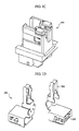
- FIGS. 1C, 1D, 1E and 1F are schematic views of a lamp socket element, respectively, according to an other embodiment of the present invention.
- the lamp socket 550 includes a contact terminal 560, a housing 570 and a cover 580.
- the lamp socket 550 fixes a lamp (not shown) and serves as a connector for supplying power to the lamp.
- the contact terminal 560 includes a first contact 563 to which the electrode of the lamp is fastened and fixed, and a second contact 565 to which an inverter electrode portion of the inverter unit (not shown) is fastened and fixed.
- the housing 570 includes a base portion 573 having a space 575 to receive the contact terminal 560, and the contact terminal 560 is coupled to the housing 570 and the cover 580.
- FIG 2A is a view showing the lamp socket 500 coupled to a lower receiving member according to an embodiment of the present invention
- FIGS. 2B and 2C are plan and perspective views showing a lamp coupled to the lamp socket 500 according to an embodiment of the present invention
- FIG 3 is a schematic sectional view of a lamp according to an embodiment of the present invention.
- FIG 2A shows the lamp socket 500, which is coupled to a lower receiving member 900.
- An upper end portion of the lamp socket 500 on which the first connector 520 is formed is disposed on a top surface of the lower receiving member 900.
- a lower end portion, on which the second connector 530 is formed, is disposed on a bottom surface of the lower receiving member 900.
- the top surface of the lower receiving member 900 is the surface over which a receiving space is provided.
- the bottom surface is the surface positioned opposite the top surface.
- the lower receiving member 900 is formed with a hole (not shown) having a shape corresponding to the lamp socket 500.
- the lamp socket 500 can be fixedly inserted into the hole.
- FIGS. 2B and 2C show that lamps 400 are coupled to the lamp sockets 500.
- Some of the lamp sockets 500 are disposed at a first side of the lower receiving member 900 to be spaced apart from each other by a predetermined interval.
- Some of the lamp sockets 500 are symmetrically disposed at a second side, which is opposite the first side of the lower receiving member 900.
- each lamp 400 comprises a lamp tube 410 and electrode portions 420.
- the lamp tube 410 comprises a tube body 411, a phosphor layer 412 and discharge gas 413.
- the electrode portions 420 are disposed at both ends of the lamp tube 410, When electric power is applied to the lamp 400 through the lead wires 422 from the outside, the electric power is supplied to the lamp electrodes 421. That is, the lead wire 422 is connected to the first connector 520 of the lamp socket 500, and the electric power supplied from the outside through the second connector 530 is applied to the lamp electrode 421 through the first connector 520 and the lead wire 422.
- the discharge gas 413 in the lamp tube 410 is changed a plasma state and emits non-visible rays. Then, the non-visible rays stimulate the phosphor layer 412 to radiate visible rays to the outside.
- the cold cathode fluorescent lamp can be employed.
- FIG 4A is a schematic perspective view of an inverter unit according to an embodiment of the present invention.
- FIG 4B is an enlarged view of a portion of FIG 4A.
- an inverter unit 600 comprises inverters 610, an inverter printed circuit board 620 and inverter electrode portions 630.
- the inverter 610 converts a direct voltage supplied from the outside into an alternating voltage and outputs the alternating voltage.
- the inverter printed circuit board 620 is formed with a circuit pattern and the inverter 610 is mounted on the inverter printed circuit board 620.
- the inverter printed circuit board 620 may be further mounted with a transformer (not shown) for converting a level of the output alternating voltage, a controller (not shown) for controlling an operation of the inverter 610 and other components.
- the inverter electrode portion 630 which is an output terminal through which the alternating voltage converted through the inverter 610 is output, is formed in an end of the inverter printed circuit board 620.
- the inverter electrode portion 630 is electrically connected to the inverter 610 through the circuit patterns (not shown).
- the inverter electrode portion 630 is inserted into and connected to the second connectors 530 of the lamp sockets 500 disposed on the bottom surface of the lower receiving member 900.
- FIG. 5A is a view for illustrating a process of coupling the inverter unit 600 in a backlight unit according to an embodiment of the present invention.
- FIGS. 5B and 5C are a bottom perspective view and a side view of the backlight unit, respectively, according to an embodiment of the present invention.
- a guide portion 910 is formed on the bottom surface of the lower receiving member 900 to guide a route along which the inverter unit 600 is coupled to or detached from the second connectors 530 of the lamp sockets 500.
- the guide portion 910 comprises first and second guides 911 a 912a respectively formed on upper and lower end portions of the bottom surface of the lower receiving member 900.
- the first and second guides 911a and 912a can be respectively formed on an upper left end portion and a lower left end portion of the bottom surface of the lower receiving member 900.
- the second connectors 530 of the lamp sockets 500 can be disposed in the left and right sides of the lower receiving member 900, respectively.
- the second connectors 530 disposed in the right side are omitted in these figures.
- Each of the first and second guides 911 a and 912a is formed to have, for example, an L-shaped cross section. That is, the first and second guides 911 a and 912a are formed to have vertical sections and horizontal sections. The vertical sections are vertically extended from the bottom surface of the lower receiving member 900. The horizontal sections are horizontally extended from the distal ends of the first sections toward each other to be parallel with the bottom surface of the lower receiving member 900.
- the guide portion 910 and the lower receiving member 900 can be integrally formed.
- a length of each vertical section of the first and second guides 911a and 912a (that is, a height of the first and second guides 911a and 912a) can be slightly larger than a thickness of the inverter printed circuit board 620, and each horizontal section of the first and second guides 911 a and 912a extends to partially cover each upper and lower end of the inverter printed circuit board 620.
- a distance between the vertical sections of the first and second guides 911a and 912a may correspond to a width of the inverter printed circuit board 620.
- the inverter unit 600 moves in a sliding manner in the left direction along the guide portion 910 toward the second connectors 530 disposed in the left side of the lower receiving member 900, so that the inverter electrode portion 630 is inserted into the second connectors 530 and electrically and mechanically connected to the second connectors 530.
- the inverter printed circuit board 620 of the inverter unit 600 is prevented from floating by the guide portion 910. Thus, a crack can be prevented from being generated on the inverter electrode portion 630 or the second connector 530.
- the guide portion 910 can be formed near the second connectors 530 disposed in the left or left end side of the lower receiving member 900. In an embodiment of the present invention, the guide portion 910 may be formed near the second connectors 530 disposed on the right side of the lower receiving member 900. In an embodiment, the guide portion 910 can be formed in both the right and left sides of the lower receiving member 900.
- the inverter unit 600 may be inserted into the second connectors 530 disposed on the left end side, on the right end side or on the left and right end sides of the lower receiving member 900.
- FIGS. 6 and 7 are views illustrating a method of coupling the inverter unit 600 to a backlight unit according to embodiments of the present invention.
- the configurations of the embodiments shown in FIGS. 6 and 7 are similar to those of the embodiment illustrated in connection with FIGS. 5A-5C, except for the guide portion 910.
- the guide portion 910 is formed on the bottom surface of the lower receiving member 900 to guide the inverter unit 600 so that the inverter unit 600 can be coupled to or detached from the second connectors 530 of the lamp sockets 500.
- the guide portion 910 may include three first guides 911b formed on an upper left side of the bottom surface of the lower receiving member 900 and three second guides 912b formed on a lower left side of the bottom surface of the lower receiving member 900 according to an embodiment of the present invention.
- the first guides 911b and the second guides 912b can be formed on an upper right side and a lower right side of the bottom surface of the lower receiving member 900.
- the first guides 911b are spaced apart from each other by an interval
- the second guides 912b are also spaced apart from each other by an interval.
- Each of the first and second guides 911b and 912b is formed to have, for example, an L-shaped cross section.
- the number of the first or second guides 911 b and 912b can vary.
- the guide portion 910 is formed on the bottom surface of the lower receiving member 900 to guide the inverter unit 600 so that the inverter unit 600 can be coupled to or detached from the second connectors 530 of the lamp sockets 500.
- the guide portion 910 includes a first guide 911c formed on an upper end side, for example, an upper left end side of the bottom surface of the lower receiving member 900 and a second guide 912c formed on a lower end side, for example, a lower left end side of the bottom surface of the lower receiving member 900 according to an embodiment of the present invention.
- Each of the first and second guides 911c and 912c is formed to have, for example, an L-shaped cross section.
- Protrusions 925a and 925b are respectively formed on both top and bottom ends of the inverter printed circuit board 620.
- the first and second guides 911c and 912c are configured such that the first and second guides 911c and 912c can receive the protrusions 925a and 925b when the inverter unit 600 is inserted into the second connectors 530,
- the inverter unit 600 moves along the first and second guides 911c and 911c and then the inverter unit 600 is inserted into the second connectors 530 of the lamp sockets 500, the protrusions 925a and 925b formed on both the top and bottom ends of the inverter printed circuit board 620 of the inverter unit 600 are prevented from floating by the guide portion 910, whereby the entire inverter printed circuit board 620 is also prevented from floating. As a result, a crack can be prevented from being generated on the inverter electrode portion 630 or the second connector 530.
- FIG 8A is an exploded perspective view of a liquid crystal display device having a backlight unit according to an embodiment of the present invention.
- FIG 8B is a bottom perspective view of a lower receiving member shown in FIG. 8A.
- the liquid crystal display device comprises an upper receiving member 300, a liquid crystal display (LCD) panel 100, driving circuit units 220 and 240, a mold frame 800, a plurality of optical sheets 710, a diffusion plate 720, lamps 400 and a lower receiving member 900.
- LCD liquid crystal display
- a first driving circuit unit 220 comprises a gate side printed circuit board 224 connected to the LCD panel 100 and having a control integrated circuit (IC) mounted on the gate side printed circuit board 224 to apply a gate signal to a gate line of a thin film transistor (TFT) substrate 120.
- a second driving circuit unit 240 includes a data side printed circuit board 244 connected to the LCD panel 100 and having a control IC mounted on the data side printed circuit board 244 to apply a data signal to a data line of the TFT substrate 120.
- the second driving circuit unit 220 includes a gate side flexible printed circuit board 222 for connecting the TFT substrate 120 and the gate side printed circuit board 224.
- the first driving circuit unit 240 includes a data side flexible printed circuit board 242 for connecting the TFT substrate 120 and the data side printed circuit board 244.
- the gate and data side printed circuit boards 224 and 244 are connected to the gate and data side flexible printed circuit boards 222 and 242, respectively, to apply gate driving signals and external image signals. According to an embodiment of the present invention, the gate and data side printed circuit boards 224 and 244 may be integrated to form a single printed circuit board.
- Driving ICs (not shown) can be mounted to the flexible printed circuit boards 222 and 242 to transmit, for example, red, green and blue (R, G, B) signals or power generated in the printed circuit boards 224 and 244 to the liquid crystal panel 100.
- the upper receiving member 300 can be formed, for example, in a rectangular frame shape having flat and side wall sections, which have a perpendicularly-bent shape, to prevent the liquid crystal display panel 100 and the driving circuit units 220 and 240 from being deviated.
- the upper receiving member 300 protects the liquid crystal panel 100 and the driving circuit units 220 and 240 against a shock applied from the outside.
- the plurality of optical sheets 710, the diffusion plate 720, one or more lamps 400 and the reflection plate 600 are stacked sequentially to be received by the mold frame 800.
- the lower receiving member 900 is provided to be coupled to the mold frame 800 and support other components.
- the lamp sockets 500 can be fixedly coupled to both opposite sides of the lower receiving member 900.
- the lamps 400 are connected to the first connectors 520 formed in the upper end portions of the lamp sockets 500 and the inverter unit 600 is connected to the second connectors 530 formed in the lower end portions.
- the guide portion 910 (911a and 912a, 911b and 912b, or 911c and 912c) is formed on the bottom surface of the lower receiving member 900 to guide the inverter unit 600 so that the inverter unit 600 can be coupled to or detached from the second connectors 530 of the lamp sockets 500.
- the guide portion is formed on the lower receiving member of the backlight unit to guide the inverter unit so that the inverter unit can be coupled to or detached from the lower receiving member.
- the inverter unit is prevented from floating when the inverter unit is coupled to or detached from the connector of the lamp socket in a sliding manner.
- a crack or damage can be prevented from being generated on the inverter.
Landscapes
- Engineering & Computer Science (AREA)
- General Engineering & Computer Science (AREA)
- Mechanical Engineering (AREA)
- Transportation (AREA)
- Planar Illumination Modules (AREA)
- Braking Arrangements (AREA)
Abstract
Description
- The present disclosure relates to a backlight unit and a liquid crystal display device having the same, and more particularly, to a backlight unit having a crack prevention structure and a liquid crystal display device having the same.
- In a liquid crystal display (LCD) device, an inverter is used to drive a backlight unit. The inverter is connected to a lamp by a variety of methods. The lamp and the inverter can be connected to each other using a wire and a connector. However, when the inverter is coupled to or detached from the lamp, the lamp must be disassembled to rework the inverter.
- Instead of using the wire and connector, an inverter electrode portion can be inserted in a connector using a sliding method. In the sliding method, assembly and disassembly efficiency can be enhanced. However, a crack can be generated on the inverter electrode portion or the connector in which the inverter electrode portion is inserted. Since the inverter uses electric power of high voltage, if a crack is generated in a component of the inverter, a lamp may operate abnormally and the inverter can be burned.
- According to an embodiment of the present invention, a backlight unit has a crack prevention structure for preventing a crack from being generated in an inverter unit coupled to a lamp socket.
- According to an embodiment of the present invention, a backlight unit comprises a receiving member, a lamp socket disposed in the receiving member, a lamp coupled to the lamp socket, and an inverter unit coupled to the lamp socket to supply electric power to the lamp.
- The receiving member may further comprise a guide portion for guiding the inverter unit.
- The lamp socket may comprise a body, a first connector formed in a first end of the body, and a second connector formed in a second end of the body.
- The first connector of the lamp socket may be disposed on a first surface of the receiving member and the second connector is disposed on a second surface of the receiving member.
- A first portion of the lamp socket may be disposed on a first side of the receiving member and a second portion of the lamp socket may be disposed on a second side of the receiving member.
- The lamp may comprise a lamp tube having a discharge gas and a phosphor layer and electrode portions provided at both ends of the lamp tube.
- The electrode portion can be coupled to the first connector of the lamp socket.
- The inverter unit may comprise an inverter, an inverter printed circuit board having the inverter mounted thereon, and an inverter electrode portion formed in an end of the inverter printed circuit board.
- The inverter electrode portion is connected to the second connector of the lamp socket.
- The inverter electrode portion is formed at the end of the inverter printed circuit board to protrude the second connector of the receiving member.
- The inverter printed circuit board has protrusions formed at both top and bottom ends of the inverter printed circuit board to be received by a corresponding guide portion of the receiving member.
- The guide portion may comprise a first guide formed at a first side of the receiving member, and a second guide formed at a second side of the receiving member, the second guide being opposite to the first guide.
- Each of the first and second guides may be bent into a predetermined shape,
- The predetermined shape has an L-shaped cross section.
- The guide portion and the receiving member may be integrally formed.
- The guide portion may comprise a plurality of first guides and a plurality of second guides, the plurality of first guides are spaced apart from each other by an interval and the plurality of second guides are spaced apart from each other by an interval.
- According to an embodiment of the present invention, a liquid crystal display device comprises a liquid crystal display panel for displaying an image, and a backlight unit including a receiving member, a lamp socket disposed in the receiving member, a lamp coupled to a first portion of the lamp socket, and an inverter unit coupled to a second portion of the lamp socket to supply electric power to the lamp, wherein the first portion is positioned opposite the second portion.
- The receiving member may further comprise a guide portion for guiding the inverter unit,
- Exemplary embodiments of the present invention can be understood in more detail from the following descriptions taken in conjunction with the accompanying drawings, in which:
- FIGS. 1A and 1B are schematic perspective and side views of a lamp socket, respectively, according to an embodiment of the present invention;
- FIGS. 1C, 1D, 1E and 1F are schematic views of a lamp socket element, respectively, according to an other embodiment of the present invention.
- FIG. 2A is a view showing a lamp socket coupled to a lower receiving member according to an embodiment of the present invention;
- FIGS. 2B and 2C are plan and perspective views, respectively, showing a lamp coupled to a lamp socket according to an embodiment of the present invention;
- FIG 3 is a schematic sectional view of a lamp according to an embodiment of the present invention;
- FIG 4A is a schematic perspective view of an inverter unit according to an embodiment of the present invention;
- FIG 4B is an enlarged view of a portion of FIG. 4A;
- FIG. 5A is a view for illustrating a process of coupling an inverter unit in a backlight unit according to an embodiment of the present invention;
- FIGS. 5B and 5C are a bottom perspective view and a side view of a backlight unit, respectively, according to an embodiment of the present invention;
- FIG 6 illustrates a method of coupling an inverter unit to a backlight unit according to an embodiment of the present invention;
- FIG. 7 illustrates a method of coupling an inverter unit to a backlight unit according to an embodiment of the present invention;
- FIG. 8A is an exploded perspective view of a liquid crystal display device having a backlight unit according to an embodiment of the present invention; and
- FIG. 8B is a bottom perspective view of a lower receiving member shown in FIG. 8A according to an embodiment of the present invention.
- Exemplary embodiments of the present invention will be described in more detail with references to the accompanying drawings. The present invention may be embodied in many different forms and should not be construed as limited to the embodiments set forth herein.
- FIGS. 1A and 1B are schematic perspective and side views of a lamp socket, respectively, according to an embodiment of the present invention.
- Referring to FIGS. 1A and 1B, a
lamp socket 500 comprises abody 510, afirst connector 520 and asecond connector 530. - The
first connector 520 is formed at an end of thebody 510, for example, an upper end of the body. Thesecond connector 530 is formed near the other end of thebody 510, for example, a lower end of the body. Thefirst connector 520 is provided with a space for receiving an end of a lamp. An electrode portion of the lamp is inserted into thefirst connector 520, thereby being electrically and mechanically coupled to thefirst connector 520. An electrode portion of an inverter is inserted into and connected to thesecond connector 530 to supply electric power to the electrode portion of the lamp connected to the first connector. The first andsecond connectors body 510. The electrode portions of the lamp and inverter are connected to each other through the first andsecond connectors lamp socket 500. - FIGS. 1C, 1D, 1E and 1F are schematic views of a lamp socket element, respectively, according to an other embodiment of the present invention.
- Referring to FIGS. 1A to 1F, the
lamp socket 550 includes acontact terminal 560, ahousing 570 and acover 580. Thelamp socket 550 fixes a lamp (not shown) and serves as a connector for supplying power to the lamp. Thecontact terminal 560 includes afirst contact 563 to which the electrode of the lamp is fastened and fixed, and asecond contact 565 to which an inverter electrode portion of the inverter unit (not shown) is fastened and fixed. Thehousing 570 includes abase portion 573 having aspace 575 to receive thecontact terminal 560, and thecontact terminal 560 is coupled to thehousing 570 and thecover 580. - FIG 2A is a view showing the
lamp socket 500 coupled to a lower receiving member according to an embodiment of the present invention, FIGS. 2B and 2C are plan and perspective views showing a lamp coupled to thelamp socket 500 according to an embodiment of the present invention. FIG 3 is a schematic sectional view of a lamp according to an embodiment of the present invention. - FIG 2A shows the
lamp socket 500, which is coupled to alower receiving member 900. An upper end portion of thelamp socket 500 on which thefirst connector 520 is formed is disposed on a top surface of thelower receiving member 900. A lower end portion, on which thesecond connector 530 is formed, is disposed on a bottom surface of thelower receiving member 900. The top surface of thelower receiving member 900 is the surface over which a receiving space is provided. The bottom surface is the surface positioned opposite the top surface. Thelower receiving member 900 is formed with a hole (not shown) having a shape corresponding to thelamp socket 500. Thelamp socket 500 can be fixedly inserted into the hole. - FIGS. 2B and 2C show that
lamps 400 are coupled to thelamp sockets 500. Some of thelamp sockets 500 are disposed at a first side of thelower receiving member 900 to be spaced apart from each other by a predetermined interval. Some of thelamp sockets 500 are symmetrically disposed at a second side, which is opposite the first side of thelower receiving member 900. - Referring to FIG 3, each
lamp 400 comprises alamp tube 410 andelectrode portions 420. Thelamp tube 410 comprises atube body 411, aphosphor layer 412 anddischarge gas 413. Theelectrode portions 420, each of which includes alamp electrode 421 and alead wire 422, are disposed at both ends of thelamp tube 410, When electric power is applied to thelamp 400 through thelead wires 422 from the outside, the electric power is supplied to thelamp electrodes 421. That is, thelead wire 422 is connected to thefirst connector 520 of thelamp socket 500, and the electric power supplied from the outside through thesecond connector 530 is applied to thelamp electrode 421 through thefirst connector 520 and thelead wire 422. When the electric power is applied to thelamp electrodes 421, thedischarge gas 413 in thelamp tube 410 is changed a plasma state and emits non-visible rays. Then, the non-visible rays stimulate thephosphor layer 412 to radiate visible rays to the outside. - In an embodiment of the present invention, the cold cathode fluorescent lamp can be employed.
- FIG 4A is a schematic perspective view of an inverter unit according to an embodiment of the present invention. FIG 4B is an enlarged view of a portion of FIG 4A.
- Referring to FIGS. 4A and 4B, an
inverter unit 600 comprisesinverters 610, an inverter printedcircuit board 620 andinverter electrode portions 630. - Since the cold cathode fluorescent lamp operates using an alternating voltage, to operate the cold cathode fluorescent lamp, the
inverter 610 converts a direct voltage supplied from the outside into an alternating voltage and outputs the alternating voltage. - The inverter printed
circuit board 620 is formed with a circuit pattern and theinverter 610 is mounted on the inverter printedcircuit board 620. The inverter printedcircuit board 620 may be further mounted with a transformer (not shown) for converting a level of the output alternating voltage, a controller (not shown) for controlling an operation of theinverter 610 and other components. - The
inverter electrode portion 630, which is an output terminal through which the alternating voltage converted through theinverter 610 is output, is formed in an end of the inverter printedcircuit board 620. Theinverter electrode portion 630 is electrically connected to theinverter 610 through the circuit patterns (not shown). Theinverter electrode portion 630 is inserted into and connected to thesecond connectors 530 of thelamp sockets 500 disposed on the bottom surface of thelower receiving member 900. - FIG. 5A is a view for illustrating a process of coupling the
inverter unit 600 in a backlight unit according to an embodiment of the present invention. FIGS. 5B and 5C are a bottom perspective view and a side view of the backlight unit, respectively, according to an embodiment of the present invention. - Referring to FIGS. 5A to 5C, a
guide portion 910 is formed on the bottom surface of thelower receiving member 900 to guide a route along which theinverter unit 600 is coupled to or detached from thesecond connectors 530 of thelamp sockets 500. - In an embodiment, the
guide portion 910 comprises first andsecond guides 911 a 912a respectively formed on upper and lower end portions of the bottom surface of thelower receiving member 900. In an embodiment, the first andsecond guides lower receiving member 900. Thesecond connectors 530 of thelamp sockets 500 can be disposed in the left and right sides of thelower receiving member 900, respectively. Thesecond connectors 530 disposed in the right side are omitted in these figures. - Each of the first and
second guides second guides lower receiving member 900. The horizontal sections are horizontally extended from the distal ends of the first sections toward each other to be parallel with the bottom surface of thelower receiving member 900. - In an embodiment of the present invention, the
guide portion 910 and thelower receiving member 900 can be integrally formed. In an embodiment of the present invention, a length of each vertical section of the first andsecond guides second guides circuit board 620, and each horizontal section of the first andsecond guides circuit board 620. In an embodiment of the present invention, a distance between the vertical sections of the first andsecond guides circuit board 620. - The
inverter unit 600 moves in a sliding manner in the left direction along theguide portion 910 toward thesecond connectors 530 disposed in the left side of thelower receiving member 900, so that theinverter electrode portion 630 is inserted into thesecond connectors 530 and electrically and mechanically connected to thesecond connectors 530. - If the
inverter unit 600 moves along theguide portion 910 and theinverter electrode portions 630 are inserted into thesecond connectors 530 of thelamp sockets 500, the inverter printedcircuit board 620 of theinverter unit 600 is prevented from floating by theguide portion 910. Thus, a crack can be prevented from being generated on theinverter electrode portion 630 or thesecond connector 530. - In an embodiment of the present invention, the
guide portion 910 can be formed near thesecond connectors 530 disposed in the left or left end side of thelower receiving member 900. In an embodiment of the present invention, theguide portion 910 may be formed near thesecond connectors 530 disposed on the right side of thelower receiving member 900. In an embodiment, theguide portion 910 can be formed in both the right and left sides of thelower receiving member 900. Theinverter unit 600 may be inserted into thesecond connectors 530 disposed on the left end side, on the right end side or on the left and right end sides of thelower receiving member 900. - FIGS. 6 and 7 are views illustrating a method of coupling the
inverter unit 600 to a backlight unit according to embodiments of the present invention. The configurations of the embodiments shown in FIGS. 6 and 7 are similar to those of the embodiment illustrated in connection with FIGS. 5A-5C, except for theguide portion 910. Referring to FIG 6, theguide portion 910 is formed on the bottom surface of thelower receiving member 900 to guide theinverter unit 600 so that theinverter unit 600 can be coupled to or detached from thesecond connectors 530 of thelamp sockets 500. Theguide portion 910 may include threefirst guides 911b formed on an upper left side of the bottom surface of thelower receiving member 900 and threesecond guides 912b formed on a lower left side of the bottom surface of thelower receiving member 900 according to an embodiment of the present invention. In an embodiment of the present invention, thefirst guides 911b and thesecond guides 912b can be formed on an upper right side and a lower right side of the bottom surface of thelower receiving member 900. Thefirst guides 911b are spaced apart from each other by an interval, and thesecond guides 912b are also spaced apart from each other by an interval. Each of the first andsecond guides second guides - Referring to FIG 7, the
guide portion 910 is formed on the bottom surface of thelower receiving member 900 to guide theinverter unit 600 so that theinverter unit 600 can be coupled to or detached from thesecond connectors 530 of thelamp sockets 500. Theguide portion 910 includes afirst guide 911c formed on an upper end side, for example, an upper left end side of the bottom surface of thelower receiving member 900 and asecond guide 912c formed on a lower end side, for example, a lower left end side of the bottom surface of thelower receiving member 900 according to an embodiment of the present invention. Each of the first andsecond guides -
Protrusions circuit board 620. The first andsecond guides second guides protrusions inverter unit 600 is inserted into thesecond connectors 530, - If the
inverter unit 600 moves along the first andsecond guides inverter unit 600 is inserted into thesecond connectors 530 of thelamp sockets 500, theprotrusions circuit board 620 of theinverter unit 600 are prevented from floating by theguide portion 910, whereby the entire inverter printedcircuit board 620 is also prevented from floating. As a result, a crack can be prevented from being generated on theinverter electrode portion 630 or thesecond connector 530. - FIG 8A is an exploded perspective view of a liquid crystal display device having a backlight unit according to an embodiment of the present invention. FIG 8B is a bottom perspective view of a lower receiving member shown in FIG. 8A.
- Referring to FIGS. 8A and 8B, the liquid crystal display device comprises an
upper receiving member 300, a liquid crystal display (LCD) panel 100, drivingcircuit units mold frame 800, a plurality ofoptical sheets 710, adiffusion plate 720,lamps 400 and alower receiving member 900. - A first
driving circuit unit 220 comprises a gate side printedcircuit board 224 connected to the LCD panel 100 and having a control integrated circuit (IC) mounted on the gate side printedcircuit board 224 to apply a gate signal to a gate line of a thin film transistor (TFT) substrate 120. A seconddriving circuit unit 240 includes a data side printedcircuit board 244 connected to the LCD panel 100 and having a control IC mounted on the data side printedcircuit board 244 to apply a data signal to a data line of the TFT substrate 120. The seconddriving circuit unit 220 includes a gate side flexible printedcircuit board 222 for connecting the TFT substrate 120 and the gate side printedcircuit board 224. The firstdriving circuit unit 240 includes a data side flexible printedcircuit board 242 for connecting the TFT substrate 120 and the data side printedcircuit board 244. - The gate and data side printed
circuit boards circuit boards circuit boards circuit boards circuit boards - The
upper receiving member 300 can be formed, for example, in a rectangular frame shape having flat and side wall sections, which have a perpendicularly-bent shape, to prevent the liquid crystal display panel 100 and the drivingcircuit units upper receiving member 300 protects the liquid crystal panel 100 and the drivingcircuit units - The plurality of
optical sheets 710, thediffusion plate 720, one ormore lamps 400 and thereflection plate 600 are stacked sequentially to be received by themold frame 800. Thelower receiving member 900 is provided to be coupled to themold frame 800 and support other components. - The
lamp sockets 500 can be fixedly coupled to both opposite sides of thelower receiving member 900. Thelamps 400 are connected to thefirst connectors 520 formed in the upper end portions of thelamp sockets 500 and theinverter unit 600 is connected to thesecond connectors 530 formed in the lower end portions. The guide portion 910 (911a and 912a, 911b and 912b, or 911c and 912c) is formed on the bottom surface of thelower receiving member 900 to guide theinverter unit 600 so that theinverter unit 600 can be coupled to or detached from thesecond connectors 530 of thelamp sockets 500. - According to an embodiment of the present invention, the guide portion is formed on the lower receiving member of the backlight unit to guide the inverter unit so that the inverter unit can be coupled to or detached from the lower receiving member. As a result, the inverter unit is prevented from floating when the inverter unit is coupled to or detached from the connector of the lamp socket in a sliding manner. Thus, a crack or damage can be prevented from being generated on the inverter.
- Although exemplary embodiments have been described herein with reference to the accompanying drawings, it is to be understood that the present invention is not limited to these precise embodiments but various changes and modifications can be made by one skilled in the art without departing from the spirit and scope of the present invention. All such changes and modifications are intended to be included within the scope of the invention as defined by the appended claims.
Claims (19)
- A backlight unit, comprising:a receiving member;a lamp socket disposed in the receiving member;a lamp coupled to the lamp socket; andan inverter unit coupled to the lamp socket to supply electric power to the lamp,wherein the receiving member further comprises a guide portion for guiding the inverter unit, and
wherein the lamp socket comprises a body, a first connector formed in a first end of the body, and a second connector formed in a second end of the body, wherein the first connector connects to the lamp and the second connector connects to the inverter unit. - The backlight unit of claim 1, wherein the first connector of the lamp socket is disposed on a first surface of the receiving member and the second connector is disposed on a second surface of the receiving member.
- The backlight unit of claim 1, wherein a first portion of the lamp socket is disposed on a first side of the receiving member and a second portion of the lamp socket is disposed on a second side of the receiving member.
- The backlight unit of claim 1, wherein the lamp comprises a lamp tube having a discharge gas and a phosphor layer, and electrode portions provided at both ends of the lamp tube.
- The backlight unit of claim 4, wherein the electrode portion is coupled to the first connector of the lamp socket.
- The backlight unit of claim 1 wherein the inverter unit comprises an inverter, an inverter printed circuit board having the inverter mounted thereon, and an inverter electrode portion formed in an end of the inverter printed circuit board.
- The backlight unit of claim 6, wherein the inverter electrode portion is connected to the second connector of the lamp socket.
- The backlight unit of claim 6, wherein the inverter electrode portion is formed at the end of the inverter printed circuit board to protrude the second connector of the receiving member.
- The backlight unit of claim 6, wherein the inverter printed circuit board has protrusions formed at both top and bottom ends of the inverter printed circuit board to be received by a corresponding guide portion of the receiving member.
- The backlight unit of claim 1, wherein the guide portion comprises a first guide formed at a first side of the receiving member, and a second guide formed at a second side of the receiving member, wherein the second guide is formed opposite the first guide,
- The backlight unit of claim 10, wherein each of the first and second guides is bent into a predetermined shape.
- The backlight unit of claim 11, wherein the predetermined shape has an L-shaped cross section.
- The backlight unit of claim 10, wherein the guide portion and the receiving member are integrally formed.
- The backlight unit of claim 10, wherein the guide portion comprises a plurality of first guides and a plurality of second guides, the plurality of first guides are spaced apart from each other by an interval and the plurality of second guides are spaced apart from each other by an interval.
- The backlight unit of claim 1, wherein the inverter unit is moved in a sliding manner, and is inserted into the second connectors.
- The backligltt unit of claim 1, wherein the lamp socket comprises a contact terminal, a housing and a cover, and
wherein the contact terminal includes a first contact and a second contact, and the housing includes a base portion having a space to receive the contact terminal, and
wherein the lamp is fastened and fixed to the first contact, an inverter electrode portion of the inverter unit is fastened and fixed to the second contact, and the contact terminal is coupled to the housing and the cover. - A liquid crystal display device, comprising:a liquid crystal display panel for displaying an image; anda backlight unit including a receiving member, a lamp socket disposed in thereceiving member, a lamp coupled to the lamp socket , and an inverter unit coupled to the lamp socket to supply electric power to the lamp,wherein the receiving member further comprises a guide portion for guiding the inverter unit, and wherein the lamp socket comprises a body, a first connector formed in a first end of the body, and a second connector formed in a second end of the body, wherein the first connector connects to the lamp and the second connector connects to the inverter unit.
- The liquid crystal display device of claim 17, wherein the inverter unit is moved in a sliding manner, and is inserted into the second connectors.
- The liquid crystal display device of claim 17, wherein the lamp socket comprises a contact terminal, a housing and a cover, and
wherein the contact terminal includes a first contact and a second contact, and the housing includes a base portion having a space to receive the contact terminal, and
wherein the lamp is fastened and fixed to the first contact, an inverter electrode portion of the inverter unit is fastened and fixed to the second contact, and the contact terminal is coupled to the housing and the cover.
Applications Claiming Priority (1)
| Application Number | Priority Date | Filing Date | Title |
|---|---|---|---|
| KR1020060067882A KR20080008518A (en) | 2006-07-20 | 2006-07-20 | Wedge brake device of vehicle |
Publications (3)
| Publication Number | Publication Date |
|---|---|
| EP1881566A2 true EP1881566A2 (en) | 2008-01-23 |
| EP1881566A3 EP1881566A3 (en) | 2009-11-25 |
| EP1881566B1 EP1881566B1 (en) | 2011-06-15 |
Family
ID=38617493
Family Applications (1)
| Application Number | Title | Priority Date | Filing Date |
|---|---|---|---|
| EP07014235A Not-in-force EP1881566B1 (en) | 2006-07-20 | 2007-07-20 | Backlight unit and liquid crystal display device having same |
Country Status (2)
| Country | Link |
|---|---|
| EP (1) | EP1881566B1 (en) |
| KR (1) | KR20080008518A (en) |
Families Citing this family (2)
| Publication number | Priority date | Publication date | Assignee | Title |
|---|---|---|---|---|
| KR101350571B1 (en) * | 2007-06-18 | 2014-01-10 | 현대모비스 주식회사 | Wheel jamming protected typed wedge assembly for Vehicle Brake Sysrem |
| KR101028958B1 (en) * | 2008-12-18 | 2011-04-12 | 한국델파이주식회사 | Electric Drive Wedge Brakes for Vehicles |
Family Cites Families (4)
| Publication number | Priority date | Publication date | Assignee | Title |
|---|---|---|---|---|
| KR100784804B1 (en) * | 2001-05-07 | 2007-12-14 | 삼성전자주식회사 | Liquid Crystal Display and Manufacturing Method |
| KR100937704B1 (en) * | 2003-02-12 | 2010-01-20 | 삼성전자주식회사 | Backlight assembly |
| JP4719486B2 (en) * | 2004-10-01 | 2011-07-06 | 三星電子株式会社 | Backlight assembly and display device having the same |
| KR20060054833A (en) * | 2004-11-16 | 2006-05-23 | 삼성전자주식회사 | Back light assembly and display device having same |
-
2006
- 2006-07-20 KR KR1020060067882A patent/KR20080008518A/en not_active Withdrawn
-
2007
- 2007-07-20 EP EP07014235A patent/EP1881566B1/en not_active Not-in-force
Also Published As
| Publication number | Publication date |
|---|---|
| EP1881566A3 (en) | 2009-11-25 |
| KR20080008518A (en) | 2008-01-24 |
| EP1881566B1 (en) | 2011-06-15 |
Similar Documents
| Publication | Publication Date | Title |
|---|---|---|
| US7674006B2 (en) | Backlight unit and liquid crystal display device having same | |
| KR100925546B1 (en) | Backlight unit and liquid crystal display module including the same | |
| KR101301954B1 (en) | backlight unit for Liquid crystal display module the same | |
| CN103017016B (en) | Light emitting module and the backlight assembly including this light emitting module | |
| CN101089703A (en) | Backlight assembly, liquid crystal display having the same and method thereof | |
| KR101365030B1 (en) | Outdoor display apparatus | |
| EP1881566B1 (en) | Backlight unit and liquid crystal display device having same | |
| US7944518B2 (en) | Liquid crystal display device | |
| CN100523950C (en) | Backlight unit and method of driving the same | |
| CN101960216A (en) | Illuminator, display, and television receiver | |
| US8154505B2 (en) | Backlight module having a chambered circuit board | |
| KR101008646B1 (en) | LED backlight unit | |
| KR101318224B1 (en) | Backlight unit of LCD | |
| US20090135584A1 (en) | Light emitting module | |
| KR20060111269A (en) | Power supply, backlight assembly and display device having same | |
| KR200440245Y1 (en) | Lamp circuit board | |
| KR20060030373A (en) | Display with flexible circuit board, backlight assembly with flexible circuit board and backlight assembly | |
| KR20130011591A (en) | Led illuminating device | |
| KR101009681B1 (en) | Backlight unit and liquid crystal display module using same | |
| KR20090061994A (en) | Back light assembly and display device having same | |
| CN101435561B (en) | Backlight unit and manufacture method thereof | |
| KR20070078113A (en) | Power supply and liquid crystal display having the same | |
| KR20070078467A (en) | Liquid crystal display | |
| KR20070068113A (en) | Backlight Unit and Liquid Crystal Display | |
| KR20070058182A (en) | Backlight unit and liquid crystal display including the same |
Legal Events
| Date | Code | Title | Description |
|---|---|---|---|
| PUAI | Public reference made under article 153(3) epc to a published international application that has entered the european phase |
Free format text: ORIGINAL CODE: 0009012 |
|
| AK | Designated contracting states |
Kind code of ref document: A2 Designated state(s): AT BE BG CH CY CZ DE DK EE ES FI FR GB GR HU IE IS IT LI LT LU LV MC MT NL PL PT RO SE SI SK TR |
|
| AX | Request for extension of the european patent |
Extension state: AL BA HR MK YU |
|
| PUAL | Search report despatched |
Free format text: ORIGINAL CODE: 0009013 |
|
| AK | Designated contracting states |
Kind code of ref document: A3 Designated state(s): AT BE BG CH CY CZ DE DK EE ES FI FR GB GR HU IE IS IT LI LT LU LV MC MT NL PL PT RO SE SI SK TR |
|
| AX | Request for extension of the european patent |
Extension state: AL BA HR MK RS |
|
| RIC1 | Information provided on ipc code assigned before grant |
Ipc: H01R 13/11 20060101AFI20071101BHEP Ipc: G02F 1/13357 20060101ALI20091016BHEP |
|
| 17P | Request for examination filed |
Effective date: 20100330 |
|
| 17Q | First examination report despatched |
Effective date: 20100427 |
|
| AKX | Designation fees paid |
Designated state(s): DE FR GB NL |
|
| GRAP | Despatch of communication of intention to grant a patent |
Free format text: ORIGINAL CODE: EPIDOSNIGR1 |
|
| GRAS | Grant fee paid |
Free format text: ORIGINAL CODE: EPIDOSNIGR3 |
|
| GRAA | (expected) grant |
Free format text: ORIGINAL CODE: 0009210 |
|
| AK | Designated contracting states |
Kind code of ref document: B1 Designated state(s): DE FR GB NL |
|
| REG | Reference to a national code |
Ref country code: GB Ref legal event code: FG4D |
|
| REG | Reference to a national code |
Ref country code: DE Ref legal event code: R096 Ref document number: 602007015162 Country of ref document: DE Effective date: 20110721 |
|
| REG | Reference to a national code |
Ref country code: NL Ref legal event code: T3 |
|
| REG | Reference to a national code |
Ref country code: DE Ref legal event code: R082 Ref document number: 602007015162 Country of ref document: DE Representative=s name: DR. WEITZEL & PARTNER, DE |
|
| PLBE | No opposition filed within time limit |
Free format text: ORIGINAL CODE: 0009261 |
|
| STAA | Information on the status of an ep patent application or granted ep patent |
Free format text: STATUS: NO OPPOSITION FILED WITHIN TIME LIMIT |
|
| 26N | No opposition filed |
Effective date: 20120316 |
|
| REG | Reference to a national code |
Ref country code: DE Ref legal event code: R097 Ref document number: 602007015162 Country of ref document: DE Effective date: 20120316 |
|
| REG | Reference to a national code |
Ref country code: NL Ref legal event code: SD Effective date: 20121017 |
|
| REG | Reference to a national code |
Ref country code: FR Ref legal event code: TP Owner name: SAMSUNG DISPLAY CO. LTD, KR Effective date: 20130226 |
|
| REG | Reference to a national code |
Ref country code: GB Ref legal event code: 732E Free format text: REGISTERED BETWEEN 20130307 AND 20130313 |
|
| REG | Reference to a national code |
Ref country code: DE Ref legal event code: R082 Ref document number: 602007015162 Country of ref document: DE Representative=s name: DR. WEITZEL & PARTNER, DE |
|
| REG | Reference to a national code |
Ref country code: DE Ref legal event code: R082 Ref document number: 602007015162 Country of ref document: DE Representative=s name: DR. WEITZEL & PARTNER, DE Effective date: 20110928 Ref country code: DE Ref legal event code: R081 Ref document number: 602007015162 Country of ref document: DE Owner name: SAMSUNG DISPLAY CO., LTD., KR Free format text: FORMER OWNER: SAMSUNG ELECTRONICS CO., LTD., SUWON-SI, KR Effective date: 20130422 Ref country code: DE Ref legal event code: R082 Ref document number: 602007015162 Country of ref document: DE Representative=s name: DR. WEITZEL & PARTNER, DE Effective date: 20130422 Ref country code: DE Ref legal event code: R081 Ref document number: 602007015162 Country of ref document: DE Owner name: SAMSUNG DISPLAY CO., LTD., YONGIN-CITY, KR Free format text: FORMER OWNER: SAMSUNG ELECTRONICS CO., LTD., SUWON-SI, GYEONGGI-DO, KR Effective date: 20130422 Ref country code: DE Ref legal event code: R082 Ref document number: 602007015162 Country of ref document: DE Representative=s name: DR. WEITZEL & PARTNER PATENT- UND RECHTSANWAEL, DE Effective date: 20110928 Ref country code: DE Ref legal event code: R082 Ref document number: 602007015162 Country of ref document: DE Representative=s name: DR. WEITZEL & PARTNER PATENT- UND RECHTSANWAEL, DE Effective date: 20130422 |
|
| REG | Reference to a national code |
Ref country code: FR Ref legal event code: PLFP Year of fee payment: 9 |
|
| PGFP | Annual fee paid to national office [announced via postgrant information from national office to epo] |
Ref country code: GB Payment date: 20150623 Year of fee payment: 9 |
|
| PGFP | Annual fee paid to national office [announced via postgrant information from national office to epo] |
Ref country code: NL Payment date: 20150623 Year of fee payment: 9 |
|
| PGFP | Annual fee paid to national office [announced via postgrant information from national office to epo] |
Ref country code: DE Payment date: 20150626 Year of fee payment: 9 |
|
| PGFP | Annual fee paid to national office [announced via postgrant information from national office to epo] |
Ref country code: FR Payment date: 20150625 Year of fee payment: 9 |
|
| REG | Reference to a national code |
Ref country code: DE Ref legal event code: R119 Ref document number: 602007015162 Country of ref document: DE |
|
| REG | Reference to a national code |
Ref country code: NL Ref legal event code: MM Effective date: 20160801 |
|
| GBPC | Gb: european patent ceased through non-payment of renewal fee |
Effective date: 20160720 |
|
| PG25 | Lapsed in a contracting state [announced via postgrant information from national office to epo] |
Ref country code: DE Free format text: LAPSE BECAUSE OF NON-PAYMENT OF DUE FEES Effective date: 20170201 Ref country code: FR Free format text: LAPSE BECAUSE OF NON-PAYMENT OF DUE FEES Effective date: 20160801 Ref country code: NL Free format text: LAPSE BECAUSE OF NON-PAYMENT OF DUE FEES Effective date: 20160801 |
|
| REG | Reference to a national code |
Ref country code: FR Ref legal event code: ST Effective date: 20170331 |
|
| PG25 | Lapsed in a contracting state [announced via postgrant information from national office to epo] |
Ref country code: GB Free format text: LAPSE BECAUSE OF NON-PAYMENT OF DUE FEES Effective date: 20160720 |