EP1881196A1 - Axial piston pump or motor of the swashplate or bent axis type - Google Patents
Axial piston pump or motor of the swashplate or bent axis type Download PDFInfo
- Publication number
- EP1881196A1 EP1881196A1 EP07010929A EP07010929A EP1881196A1 EP 1881196 A1 EP1881196 A1 EP 1881196A1 EP 07010929 A EP07010929 A EP 07010929A EP 07010929 A EP07010929 A EP 07010929A EP 1881196 A1 EP1881196 A1 EP 1881196A1
- Authority
- EP
- European Patent Office
- Prior art keywords
- control
- axial piston
- control plate
- pressure balance
- passage
- Prior art date
- Legal status (The legal status is an assumption and is not a legal conclusion. Google has not performed a legal analysis and makes no representation as to the accuracy of the status listed.)
- Granted
Links
Images

Classifications
-
- F—MECHANICAL ENGINEERING; LIGHTING; HEATING; WEAPONS; BLASTING
- F04—POSITIVE - DISPLACEMENT MACHINES FOR LIQUIDS; PUMPS FOR LIQUIDS OR ELASTIC FLUIDS
- F04B—POSITIVE-DISPLACEMENT MACHINES FOR LIQUIDS; PUMPS
- F04B1/00—Multi-cylinder machines or pumps characterised by number or arrangement of cylinders
- F04B1/12—Multi-cylinder machines or pumps characterised by number or arrangement of cylinders having cylinder axes coaxial with, or parallel or inclined to, main shaft axis
- F04B1/20—Multi-cylinder machines or pumps characterised by number or arrangement of cylinders having cylinder axes coaxial with, or parallel or inclined to, main shaft axis having rotary cylinder block
- F04B1/2014—Details or component parts
- F04B1/2042—Valves
-
- F—MECHANICAL ENGINEERING; LIGHTING; HEATING; WEAPONS; BLASTING
- F01—MACHINES OR ENGINES IN GENERAL; ENGINE PLANTS IN GENERAL; STEAM ENGINES
- F01B—MACHINES OR ENGINES, IN GENERAL OR OF POSITIVE-DISPLACEMENT TYPE, e.g. STEAM ENGINES
- F01B3/00—Reciprocating-piston machines or engines with cylinder axes coaxial with, or parallel or inclined to, main shaft axis
- F01B3/0032—Reciprocating-piston machines or engines with cylinder axes coaxial with, or parallel or inclined to, main shaft axis having rotary cylinder block
- F01B3/0044—Component parts, details, e.g. valves, sealings, lubrication
- F01B3/0047—Particularities in the contacting area between cylinder barrel and valve plate
-
- F—MECHANICAL ENGINEERING; LIGHTING; HEATING; WEAPONS; BLASTING
- F03—MACHINES OR ENGINES FOR LIQUIDS; WIND, SPRING, OR WEIGHT MOTORS; PRODUCING MECHANICAL POWER OR A REACTIVE PROPULSIVE THRUST, NOT OTHERWISE PROVIDED FOR
- F03C—POSITIVE-DISPLACEMENT ENGINES DRIVEN BY LIQUIDS
- F03C1/00—Reciprocating-piston liquid engines
- F03C1/02—Reciprocating-piston liquid engines with multiple-cylinders, characterised by the number or arrangement of cylinders
- F03C1/06—Reciprocating-piston liquid engines with multiple-cylinders, characterised by the number or arrangement of cylinders with cylinder axes generally coaxial with, or parallel or inclined to, main shaft axis
- F03C1/0636—Reciprocating-piston liquid engines with multiple-cylinders, characterised by the number or arrangement of cylinders with cylinder axes generally coaxial with, or parallel or inclined to, main shaft axis having rotary cylinder block
- F03C1/0644—Component parts
- F03C1/0655—Valve means
-
- F—MECHANICAL ENGINEERING; LIGHTING; HEATING; WEAPONS; BLASTING
- F04—POSITIVE - DISPLACEMENT MACHINES FOR LIQUIDS; PUMPS FOR LIQUIDS OR ELASTIC FLUIDS
- F04B—POSITIVE-DISPLACEMENT MACHINES FOR LIQUIDS; PUMPS
- F04B1/00—Multi-cylinder machines or pumps characterised by number or arrangement of cylinders
- F04B1/12—Multi-cylinder machines or pumps characterised by number or arrangement of cylinders having cylinder axes coaxial with, or parallel or inclined to, main shaft axis
- F04B1/20—Multi-cylinder machines or pumps characterised by number or arrangement of cylinders having cylinder axes coaxial with, or parallel or inclined to, main shaft axis having rotary cylinder block
- F04B1/2014—Details or component parts
- F04B1/2021—Details or component parts characterised by the contact area between cylinder barrel and valve plate
-
- F—MECHANICAL ENGINEERING; LIGHTING; HEATING; WEAPONS; BLASTING
- F04—POSITIVE - DISPLACEMENT MACHINES FOR LIQUIDS; PUMPS FOR LIQUIDS OR ELASTIC FLUIDS
- F04B—POSITIVE-DISPLACEMENT MACHINES FOR LIQUIDS; PUMPS
- F04B27/00—Multi-cylinder pumps specially adapted for elastic fluids and characterised by number or arrangement of cylinders
- F04B27/08—Multi-cylinder pumps specially adapted for elastic fluids and characterised by number or arrangement of cylinders having cylinders coaxial with, or parallel or inclined to, main shaft axis
- F04B27/0804—Multi-cylinder pumps specially adapted for elastic fluids and characterised by number or arrangement of cylinders having cylinders coaxial with, or parallel or inclined to, main shaft axis having rotary cylinder block
- F04B27/0817—Multi-cylinder pumps specially adapted for elastic fluids and characterised by number or arrangement of cylinders having cylinders coaxial with, or parallel or inclined to, main shaft axis having rotary cylinder block arrangements for pressing the cylinder barrel against the valve plate, e.g. by fluid pressure
-
- F—MECHANICAL ENGINEERING; LIGHTING; HEATING; WEAPONS; BLASTING
- F04—POSITIVE - DISPLACEMENT MACHINES FOR LIQUIDS; PUMPS FOR LIQUIDS OR ELASTIC FLUIDS
- F04B—POSITIVE-DISPLACEMENT MACHINES FOR LIQUIDS; PUMPS
- F04B27/00—Multi-cylinder pumps specially adapted for elastic fluids and characterised by number or arrangement of cylinders
- F04B27/08—Multi-cylinder pumps specially adapted for elastic fluids and characterised by number or arrangement of cylinders having cylinders coaxial with, or parallel or inclined to, main shaft axis
- F04B27/0804—Multi-cylinder pumps specially adapted for elastic fluids and characterised by number or arrangement of cylinders having cylinders coaxial with, or parallel or inclined to, main shaft axis having rotary cylinder block
- F04B27/0821—Multi-cylinder pumps specially adapted for elastic fluids and characterised by number or arrangement of cylinders having cylinders coaxial with, or parallel or inclined to, main shaft axis having rotary cylinder block component parts, details, e.g. valves, sealings, lubrication
- F04B27/0826—Multi-cylinder pumps specially adapted for elastic fluids and characterised by number or arrangement of cylinders having cylinders coaxial with, or parallel or inclined to, main shaft axis having rotary cylinder block component parts, details, e.g. valves, sealings, lubrication particularities in the contacting area between cylinder barrel and valve plate
Definitions
- the invention relates to an axial piston pump or water, of the swashplate or bent axis type, wherein a fixed control plate, which comprises at least one control passage, consisting of a plurality of control passage sections separated from each other by bridges, is arranged between a cylinder drum, rotatable in both directions of rotation, and a fixed housing of the pump or motor.
- a fixed control plate which comprises at least one control passage, consisting of a plurality of control passage sections separated from each other by bridges, is arranged between a cylinder drum, rotatable in both directions of rotation, and a fixed housing of the pump or motor.
- control plate of this known axial piston pump in the transition regions between the control passages for the supply or removal of the operating fluid, that is to say the high pressure passage and the low pressure passage, comprises a pressure balancing passage, through which a relatively gentle adaptation of the cylinder pressures occurs, before the cylinder opening of the respective cylinder lies in the cross sectional region of the high pressure passage.
- a fluid jet which, due to jet erosion and cavitation erosion causes wear damage on the control passage walls and the control plate, passes through the pressure balancing passage.
- an interference passage is allocated to the pressure balancing passage, which produces an interference jet intersecting the fluid jet and thereby weakens this.
- the object of the invention is to provide a control plate for an axial piston pump or motor which is designed in such a way that damage to structural parts is prevented over the entire extent of the control passages for the supply and removal of the operating fluid.
- the at least one control passage, in the region at least of one bridge is provided with a pressure balance opening connecting the surfaces of the control plate with one another.
- the surfaces of the control plate in the region of the bridges, where low pressure zones can develop are reduced.
- the formation of gas or water vapour bubbles which occur as a pre-condition for cavitation is reduced so that damage by cavitation erosion to structural part surfaces cooperating with the control plate in the region of the control passages for the supply and removal of the operating fluid is prevented.
- the geometry can be adapted very simply.
- control plate can be adapted accordingly for use as an axial piston motor as well as a pump.
- the axial piston pump 1 illustrated in Fig. 1 is accommodated in a machine housing, not shown, and substantially consists of a driving flange 2, rotatably mounted in the machine housing, a cylinder drum 4 mechanically connected to the driving flange 2 by a tripod joint 3 and a housing 5, not rotatable relative to the machine housing, but pivotable about a fixed machine housing axis A over a pivoting angle range ⁇ .
- the cylinder drum 4 is rotatably mounted about the axis B via an antifriction bearing 6 on a bearing journal 7 protruding from the housing 5.
- a plurality of pistons 8, 9 displaceable in cylinder chambers 4a, parallel in axis, of the cylinder drum 4 are held on the driving flange 2 by means of a ball joint 10 and during rotation of the cylinder drum 4 perform a stroke movement dependent as to its size on the set pivoting angle ⁇ .
- the piston 8 is situated at its lowest position, wherein the entire usable operating fluid is forced out of the cylinder chamber 4a through a cylinder chamber opening 4b.
- the piston 9 is correspondingly situated in the diametrically opposite cylinder chamber at its highest position, wherein the cylinder chamber is completely filled with operating fluid.
- the delivery volume of the axial piston pump therefore depends on the set pivoting angle ⁇ of the housing 5.
- the housing 5 together with the cylinder drum 4 is swivelled about the axis A running perpendicularly to the plane of Fig. 1 into a desired position within the available pivoting angle range ⁇ .
- the stroke of the pistons 8, 9 is augmented as a result of which the delivery volume rises.
- two control passages 5a, 5b are provided in the housing 5.
- a bearing plate 11 and a control plate 12 are arranged between the cylinder drum 4 and the housing 5.
- the bearing plate 11 is connected, secured against rotation, to the cylinder drum 4. It serves as an axial bearing of the cylinder drum 4 and is provided with openings 11a, which correspond to the cylinder chamber openings 4b in size and position.
- the control plate 12 is connected, secured against rotation, to the housing 5 and can be easily replaced for maintenance reasons as well as for adaptation to various operating conditions. It is provided with a kidney-shaped control passage 12a consisting of control passage sections 12b, 12c, which are separated from each other by bridges 12d and serve to control the flow of the operating fluid into and out of the cylinder chambers 4a.
- the operating fluid is pumped from the chamber 4a via the cylinder chamber opening 4b, the openings 11 a in the bearing plate 11 and the control passage sections 12b or 12c in the control plate 12 to the control passage 5b of the housing 5, until it reaches the lowest position shown of the piston 8. From there the operating fluid flows to a port, not illustrated, where it can be removed. Another port, likewise not illustrated, serves to feed the operating fluid back to the axial piston pump 1 via the control passage 5a of the housing 5.
- a pressure balance opening 13 is provided between the control passage sections 12b, 12c, through which balancing of the pressures prevailing in the control passages 5a, 5b and in the cylinder chamber 4a or the cylinder chamber opening 4b occurs.
- the distance C from the pressure balance opening 13 to the control passage section 12b and the distance D to the control passage section 12c should be selected as large as possible. This results in an expedient arrangement of the pressure balance opening 13 in the inside or outside boundary region of the bridge 12d.
- the size and position of the pressure balance opening 13 was specified for a certain size with defined operating parameters.
- the pressure balance opening 13 thereby lies on the inner side of the bridge 12d.
- position, size and shaping of the pressure balance opening 13 can be adapted.
- control plate is suitable not only for the operation of an axial piston pump, but also for an axial piston motor.
- position and design of the pressure balance opening 13 should be adapted, based on the change in the direction of pumping or rotation.
Landscapes
- Engineering & Computer Science (AREA)
- Mechanical Engineering (AREA)
- General Engineering & Computer Science (AREA)
- Chemical & Material Sciences (AREA)
- Combustion & Propulsion (AREA)
- Physics & Mathematics (AREA)
- Fluid Mechanics (AREA)
- Reciprocating Pumps (AREA)
Abstract
Description
- The invention relates to an axial piston pump or water, of the swashplate or bent axis type, wherein a fixed control plate, which comprises at least one control passage, consisting of a plurality of control passage sections separated from each other by bridges, is arranged between a cylinder drum, rotatable in both directions of rotation, and a fixed housing of the pump or motor.
- Such an axial piston pump is described in
German Patent DE 37 25 361 C2 . In order to reduce the running noise the control plate of this known axial piston pump, in the transition regions between the control passages for the supply or removal of the operating fluid, that is to say the high pressure passage and the low pressure passage, comprises a pressure balancing passage, through which a relatively gentle adaptation of the cylinder pressures occurs, before the cylinder opening of the respective cylinder lies in the cross sectional region of the high pressure passage. During this operation a fluid jet which, due to jet erosion and cavitation erosion causes wear damage on the control passage walls and the control plate, passes through the pressure balancing passage. In order to prevent such erosion an interference passage is allocated to the pressure balancing passage, which produces an interference jet intersecting the fluid jet and thereby weakens this. - It has now been shown with axial piston pumps that also outside the transition area between the control passages for the supply and removal of the operating fluid, damage by cavitation can occur on structural part surfaces cooperating with the control plate, which cannot be prevented by a combination of a pressure balancing passage with an interference passage. In particular such erosion has been observed not only in the high pressure region, but also in the low pressure region.
- With this as the starting point the object of the invention is to provide a control plate for an axial piston pump or motor which is designed in such a way that damage to structural parts is prevented over the entire extent of the control passages for the supply and removal of the operating fluid.
- In order to achieve this object it is proposed that the at least one control passage, in the region at least of one bridge is provided with a pressure balance opening connecting the surfaces of the control plate with one another.
- Through the invention, the surfaces of the control plate in the region of the bridges, where low pressure zones can develop are reduced. Thus the formation of gas or water vapour bubbles which occur as a pre-condition for cavitation is reduced so that damage by cavitation erosion to structural part surfaces cooperating with the control plate in the region of the control passages for the supply and removal of the operating fluid is prevented. Depending on operating parameters, such as size, pressure level, speed of revolution of the cylinder drum, cylinder stroke, the geometry can be adapted very simply.
- The design of the control plate can be adapted accordingly for use as an axial piston motor as well as a pump.
- One embodiment of the invention will now be described below with reference to the accompanying drawings in which:-
- Fig. 1: a sectional view of an axial piston pump of the swashplate type,
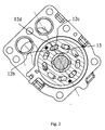
- Fig. 2: a sectional view along line E-E in Fig. 1 and
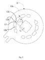
- Fig. 3: a plan view of the control plate used in the pump of Fig 1.
- The axial piston pump 1 illustrated in Fig. 1 is accommodated in a machine housing, not shown, and substantially consists of a driving
flange 2, rotatably mounted in the machine housing, acylinder drum 4 mechanically connected to thedriving flange 2 by atripod joint 3 and a housing 5, not rotatable relative to the machine housing, but pivotable about a fixed machine housing axis A over a pivoting angle range α. - The
cylinder drum 4 is rotatably mounted about the axis B via an antifriction bearing 6 on abearing journal 7 protruding from the housing 5. A plurality ofpistons cylinder chambers 4a, parallel in axis, of thecylinder drum 4 are held on the drivingflange 2 by means of aball joint 10 and during rotation of thecylinder drum 4 perform a stroke movement dependent as to its size on the set pivoting angle α. In Fig. 1 thepiston 8 is situated at its lowest position, wherein the entire usable operating fluid is forced out of thecylinder chamber 4a through a cylinder chamber opening 4b. Thepiston 9 is correspondingly situated in the diametrically opposite cylinder chamber at its highest position, wherein the cylinder chamber is completely filled with operating fluid. The delivery volume of the axial piston pump therefore depends on the set pivoting angle α of the housing 5. - In order to adjust the delivery volume the housing 5 together with the
cylinder drum 4 is swivelled about the axis A running perpendicularly to the plane of Fig. 1 into a desired position within the available pivoting angle range α. In this case, by increasing the pivoting angle the stroke of thepistons cylinder chambers 4a, twocontrol passages - A
bearing plate 11 and acontrol plate 12 are arranged between thecylinder drum 4 and the housing 5. Thebearing plate 11 is connected, secured against rotation, to thecylinder drum 4. It serves as an axial bearing of thecylinder drum 4 and is provided withopenings 11a, which correspond to thecylinder chamber openings 4b in size and position. Thecontrol plate 12 is connected, secured against rotation, to the housing 5 and can be easily replaced for maintenance reasons as well as for adaptation to various operating conditions. It is provided with a kidney-shaped control passage 12a consisting ofcontrol passage sections bridges 12d and serve to control the flow of the operating fluid into and out of thecylinder chambers 4a. - During operation of the axial piston pump with the drum moved into the pivot position illustrated in Fig. 1, the operating fluid is pumped from the
chamber 4a via the cylinder chamber opening 4b, theopenings 11 a in thebearing plate 11 and thecontrol passage sections control plate 12 to thecontrol passage 5b of the housing 5, until it reaches the lowest position shown of thepiston 8. From there the operating fluid flows to a port, not illustrated, where it can be removed. Another port, likewise not illustrated, serves to feed the operating fluid back to the axial piston pump 1 via thecontrol passage 5a of the housing 5. - Due to the rotation of the
cylinder drum 4 about thebearing journal 7 during operation, as is evident from the geometry of Fig. 2, the free cross section available for the flow of the operating fluid varies constantly, as a result of the constantly changing position of thecontrol passage sections control plate 12 relative to theopenings 11a in thebearing plate 11. Thus, a corresponding variation of the pressure and flow-rate parameters of the operating fluid also takes place. With conventional axial piston machines the hydrostatic pressure below thebridges 12d falls away steeply and gas and/or water vapour bubbles form due to the high and varying overflow-rates of the operating fluid. These bubbles are carried by the flowing fluid into regions of higher pressure, predominantly to the edges of thecontrol passages control plate 12 with the housing 5, and implode there. These implosions lead to pressure peaks, which cause erosion of the material surface at the edges of thecontrol passages - According to the invention, as is evident from Figs. 2 and 3, in order to improve the pressure and flow behaviour in the
bridges 12d, apressure balance opening 13 is provided between thecontrol passage sections control passages cylinder chamber 4a or the cylinder chamber opening 4b occurs. - So that the
bridge 12d between the adjacentcontrol passage sections control passage section 12b and the distance D to thecontrol passage section 12c should be selected as large as possible. This results in an expedient arrangement of the pressure balance opening 13 in the inside or outside boundary region of thebridge 12d. - In the present exemplary embodiment the size and position of the
pressure balance opening 13 was specified for a certain size with defined operating parameters. The pressure balance opening 13 thereby lies on the inner side of thebridge 12d. For other operating parameters (size, pressure level, number of cylinders, speed of revolution of the cylinder drum, piston stroke), position, size and shaping of thepressure balance opening 13 can be adapted. - The inventive arrangement of the control plate is suitable not only for the operation of an axial piston pump, but also for an axial piston motor. In this case, the position and design of the
pressure balance opening 13 should be adapted, based on the change in the direction of pumping or rotation.
Claims (5)
- An axial piston pump or motor (1), of the swashplate or bent axis type, wherein a fixed control plate (12), which comprises at least one control passage (12a), consisting of a plurality of control passage sections (12b, 12c) separated from each other by bridges (12d), is arranged between a cylinder drum (4), rotatable in both directions of rotation, and a fixed housing (5), characterized in that the at least one control passage (12a) in the region at least of one bridge (12d) is provided with a pressure balance opening (13) connecting the surfaces of the control plate (12) with one another.
- An axial piston machine according to Claim 1, characterized in that the pressure balance opening (13) is provided as a bore through the control plate.
- An axial pump or motor according to Claims 1 and 2, characterized in that the position of the pressure balance opening (13) is dependent on operating parameters such as piston displacement, speed of revolution, load, operating fluid etc.
- An axial pump or motor according to any one of Claims 1 to 3, characterized in that the diameter of the pressure balance opening (13) is dependent on operating parameters such as piston displacement, speed of revolution, load, operating fluid etc.
- An axial pump or motor according to Claim 1 or 2, characterized in that the pressure balance opening (13), according to operating conditions, is placed at an angle to the plane of the control plate (12).
Applications Claiming Priority (1)
| Application Number | Priority Date | Filing Date | Title |
|---|---|---|---|
| GB0614188A GB2440155A (en) | 2006-07-18 | 2006-07-18 | An axial piston pump or machine of the swashplate or bent axis type |
Publications (2)
| Publication Number | Publication Date |
|---|---|
| EP1881196A1 true EP1881196A1 (en) | 2008-01-23 |
| EP1881196B1 EP1881196B1 (en) | 2010-09-08 |
Family
ID=36955797
Family Applications (1)
| Application Number | Title | Priority Date | Filing Date |
|---|---|---|---|
| EP07010929A Active EP1881196B1 (en) | 2006-07-18 | 2007-06-02 | Axial piston pump or motor of the swashplate or bent axis type |
Country Status (4)
| Country | Link |
|---|---|
| US (1) | US8128380B2 (en) |
| EP (1) | EP1881196B1 (en) |
| DE (1) | DE602007008991D1 (en) |
| GB (1) | GB2440155A (en) |
Cited By (1)
| Publication number | Priority date | Publication date | Assignee | Title |
|---|---|---|---|---|
| CN107278242A (en) * | 2014-11-08 | 2017-10-20 | 蒙尼有限公司 | Hydraulic machine with improved oscillating axial cylinder |
Families Citing this family (5)
| Publication number | Priority date | Publication date | Assignee | Title |
|---|---|---|---|---|
| KR101297868B1 (en) * | 2007-09-19 | 2013-08-19 | 가부시키가이샤 고마쓰 세이사쿠쇼 | Hydraulic pump-motor and method of preventing pulsation of hydraulic pump-motor |
| EP2246566A2 (en) | 2009-04-20 | 2010-11-03 | Innas B.V. | Axial bearing for use in a hydraulic device, a hydraulic transformer and a vehicle with a hydraulic drive system |
| DE102018217303A1 (en) * | 2018-10-10 | 2020-04-16 | Robert Bosch Gmbh | Distribution plate for a hydrostatic axial piston machine and hydrostatic axial piston machine |
| US11898582B1 (en) | 2023-03-09 | 2024-02-13 | Dana Motion Systems Italia S.R.L. | System for a bent axis motor |
| US12516662B2 (en) | 2023-03-22 | 2026-01-06 | Dana Motion Systems Italia S.R.L. | Actuation system for a motor |
Citations (4)
| Publication number | Priority date | Publication date | Assignee | Title |
|---|---|---|---|---|
| FR1288771A (en) * | 1961-02-09 | 1962-03-30 | Council Scient Ind Res | Volumetric hydraulic machine |
| US3585901A (en) * | 1969-02-19 | 1971-06-22 | Sundstrand Corp | Hydraulic pump |
| DE10206958A1 (en) * | 2002-02-19 | 2003-08-21 | Linde Ag | Hydrostatic displacement unit has reversing aperture in form of control groove in control element |
| DE102004007933B3 (en) * | 2004-02-18 | 2005-06-16 | Sauer-Danfoss (Neumünster) GmbH & Co OHG | Axial piston engine and associated control system to dampen peak gas flow impulses by an inertia regulation passage |
Family Cites Families (11)
| Publication number | Priority date | Publication date | Assignee | Title |
|---|---|---|---|---|
| GB1031735A (en) * | 1962-10-11 | 1966-06-02 | Lely Nv C Van Der | Improvements in or relating to hydraulic pumps and motors |
| GB1082807A (en) * | 1964-11-19 | 1967-09-13 | Serck R & D Ltd | Hydraulic machines with reciprocatory pistons |
| US3633463A (en) * | 1968-12-25 | 1972-01-11 | Komatsu Mfg Co Ltd | Plunger pump or motor |
| US3699845A (en) * | 1970-07-24 | 1972-10-24 | Lucas Industries Ltd | Rotary hydraulic pumps and motors |
| US4075933A (en) * | 1976-06-04 | 1978-02-28 | Gresen Manufacturing Company | Hydraulic pump or motor |
| US4550645A (en) * | 1984-04-27 | 1985-11-05 | Sundstrand Corporation | Thin valve plate for a hydraulic unit |
| JP2606758Y2 (en) * | 1992-12-22 | 2001-01-09 | 株式会社小松製作所 | Hydraulic pump / motor cylinder chamber pressure control device |
| JPH11210878A (en) * | 1998-01-20 | 1999-08-03 | Honda Motor Co Ltd | Hydraulic control device for variable displacement hydraulic transmission |
| EP1013928A3 (en) * | 1998-12-22 | 2000-11-08 | Parker Hannifin GmbH | Swash plate axial piston pump with pulsation damping means |
| DE10034857A1 (en) * | 2000-07-18 | 2002-01-31 | Liebherr Machines Bulle S A | Hydrostatic axial piston machine |
| US7500424B2 (en) * | 2004-04-07 | 2009-03-10 | The United States Of America As Represented By The Administrator Of The U.S. Environmental Protection Agency | Hydraulic machine having pressure equalization |
-
2006
- 2006-07-18 GB GB0614188A patent/GB2440155A/en not_active Withdrawn
-
2007
- 2007-05-30 US US11/755,077 patent/US8128380B2/en not_active Expired - Fee Related
- 2007-06-02 EP EP07010929A patent/EP1881196B1/en active Active
- 2007-06-02 DE DE602007008991T patent/DE602007008991D1/en active Active
Patent Citations (4)
| Publication number | Priority date | Publication date | Assignee | Title |
|---|---|---|---|---|
| FR1288771A (en) * | 1961-02-09 | 1962-03-30 | Council Scient Ind Res | Volumetric hydraulic machine |
| US3585901A (en) * | 1969-02-19 | 1971-06-22 | Sundstrand Corp | Hydraulic pump |
| DE10206958A1 (en) * | 2002-02-19 | 2003-08-21 | Linde Ag | Hydrostatic displacement unit has reversing aperture in form of control groove in control element |
| DE102004007933B3 (en) * | 2004-02-18 | 2005-06-16 | Sauer-Danfoss (Neumünster) GmbH & Co OHG | Axial piston engine and associated control system to dampen peak gas flow impulses by an inertia regulation passage |
Cited By (1)
| Publication number | Priority date | Publication date | Assignee | Title |
|---|---|---|---|---|
| CN107278242A (en) * | 2014-11-08 | 2017-10-20 | 蒙尼有限公司 | Hydraulic machine with improved oscillating axial cylinder |
Also Published As
| Publication number | Publication date |
|---|---|
| EP1881196B1 (en) | 2010-09-08 |
| US20070289441A1 (en) | 2007-12-20 |
| GB2440155A (en) | 2008-01-23 |
| GB0614188D0 (en) | 2006-08-23 |
| US8128380B2 (en) | 2012-03-06 |
| DE602007008991D1 (en) | 2010-10-21 |
Similar Documents
| Publication | Publication Date | Title |
|---|---|---|
| JP6697379B2 (en) | Axial piston pump | |
| CN107288836B (en) | Axial plunger pump | |
| EP1881196B1 (en) | Axial piston pump or motor of the swashplate or bent axis type | |
| US9341170B2 (en) | Axial piston machine | |
| KR101587945B1 (en) | Sliding vane pump | |
| US8276503B2 (en) | Axial piston machine | |
| KR100682695B1 (en) | Valve plate and hydraulic device having same | |
| JPH07506649A (en) | Hydrostatic machine with leakage oil evacuation device | |
| CN204283776U (en) | Hydrostatic piston engine | |
| CN110388308B (en) | Axial piston machine with pressure relief to pass through drive space | |
| EP3364026B1 (en) | Variable displacement pump | |
| US7437873B2 (en) | Connection block for a hydrostatic piston machine | |
| CN112483344B (en) | Hydrostatic piston engine unit | |
| US11619203B2 (en) | Hydrostatic axial piston machine | |
| CN105089961A (en) | Hydrostatic piston machine | |
| CN110360076B (en) | Hydrostatic axial piston machine | |
| US20050180872A1 (en) | Axial piston machine having a pilot control device for damping flow pulsations and manufacturing method | |
| US2103474A (en) | Reversible planetary piston pump | |
| US20070101857A1 (en) | Hydrostatic piston machine with two hydraulic circuits | |
| US8387514B2 (en) | Hydrostatic piston machine with output volume flow in the circumferential direction | |
| US9394893B2 (en) | Oscillating slide machine that pumps different fluid mediums at different pressures | |
| CN107795448B (en) | Hydrostatic Axial Piston Machine | |
| JP6179359B2 (en) | Hydraulic piston pump / motor | |
| CN106979134B (en) | Hydrostatic axial piston engine with control disc | |
| US4117770A (en) | Axial-piston hydraulic machine |
Legal Events
| Date | Code | Title | Description |
|---|---|---|---|
| PUAI | Public reference made under article 153(3) epc to a published international application that has entered the european phase |
Free format text: ORIGINAL CODE: 0009012 |
|
| AK | Designated contracting states |
Kind code of ref document: A1 Designated state(s): AT BE BG CH CY CZ DE DK EE ES FI FR GB GR HU IE IS IT LI LT LU LV MC MT NL PL PT RO SE SI SK TR |
|
| AX | Request for extension of the european patent |
Extension state: AL BA HR MK YU |
|
| 17P | Request for examination filed |
Effective date: 20080723 |
|
| 17Q | First examination report despatched |
Effective date: 20080822 |
|
| AKX | Designation fees paid |
Designated state(s): DE FR GB IT |
|
| GRAP | Despatch of communication of intention to grant a patent |
Free format text: ORIGINAL CODE: EPIDOSNIGR1 |
|
| GRAS | Grant fee paid |
Free format text: ORIGINAL CODE: EPIDOSNIGR3 |
|
| GRAA | (expected) grant |
Free format text: ORIGINAL CODE: 0009210 |
|
| AK | Designated contracting states |
Kind code of ref document: B1 Designated state(s): DE FR GB IT |
|
| REG | Reference to a national code |
Ref country code: GB Ref legal event code: FG4D |
|
| REF | Corresponds to: |
Ref document number: 602007008991 Country of ref document: DE Date of ref document: 20101021 Kind code of ref document: P |
|
| PLBE | No opposition filed within time limit |
Free format text: ORIGINAL CODE: 0009261 |
|
| STAA | Information on the status of an ep patent application or granted ep patent |
Free format text: STATUS: NO OPPOSITION FILED WITHIN TIME LIMIT |
|
| 26N | No opposition filed |
Effective date: 20110609 |
|
| REG | Reference to a national code |
Ref country code: DE Ref legal event code: R097 Ref document number: 602007008991 Country of ref document: DE Effective date: 20110609 |
|
| REG | Reference to a national code |
Ref country code: FR Ref legal event code: PLFP Year of fee payment: 10 |
|
| REG | Reference to a national code |
Ref country code: FR Ref legal event code: PLFP Year of fee payment: 11 |
|
| REG | Reference to a national code |
Ref country code: FR Ref legal event code: PLFP Year of fee payment: 12 |
|
| PGFP | Annual fee paid to national office [announced via postgrant information from national office to epo] |
Ref country code: GB Payment date: 20180620 Year of fee payment: 12 Ref country code: IT Payment date: 20180622 Year of fee payment: 12 |
|
| GBPC | Gb: european patent ceased through non-payment of renewal fee |
Effective date: 20190602 |
|
| PG25 | Lapsed in a contracting state [announced via postgrant information from national office to epo] |
Ref country code: IT Free format text: LAPSE BECAUSE OF NON-PAYMENT OF DUE FEES Effective date: 20190602 Ref country code: GB Free format text: LAPSE BECAUSE OF NON-PAYMENT OF DUE FEES Effective date: 20190602 |
|
| PGFP | Annual fee paid to national office [announced via postgrant information from national office to epo] |
Ref country code: FR Payment date: 20210622 Year of fee payment: 15 |
|
| REG | Reference to a national code |
Ref country code: DE Ref legal event code: R084 Ref document number: 602007008991 Country of ref document: DE |
|
| PG25 | Lapsed in a contracting state [announced via postgrant information from national office to epo] |
Ref country code: FR Free format text: LAPSE BECAUSE OF NON-PAYMENT OF DUE FEES Effective date: 20220630 |
|
| P01 | Opt-out of the competence of the unified patent court (upc) registered |
Effective date: 20230518 |
|
| PGFP | Annual fee paid to national office [announced via postgrant information from national office to epo] |
Ref country code: DE Payment date: 20250618 Year of fee payment: 19 |