EP1880918A2 - Variable steering angle ratio mechanism for a vehicle steering system - Google Patents
Variable steering angle ratio mechanism for a vehicle steering system Download PDFInfo
- Publication number
- EP1880918A2 EP1880918A2 EP07111847A EP07111847A EP1880918A2 EP 1880918 A2 EP1880918 A2 EP 1880918A2 EP 07111847 A EP07111847 A EP 07111847A EP 07111847 A EP07111847 A EP 07111847A EP 1880918 A2 EP1880918 A2 EP 1880918A2
- Authority
- EP
- European Patent Office
- Prior art keywords
- toothed portion
- steering
- angle ratio
- gear
- toothed
- Prior art date
- Legal status (The legal status is an assumption and is not a legal conclusion. Google has not performed a legal analysis and makes no representation as to the accuracy of the status listed.)
- Withdrawn
Links
- 238000005242 forging Methods 0.000 claims abstract description 9
- 238000010438 heat treatment Methods 0.000 description 6
- 238000003754 machining Methods 0.000 description 6
- 238000003466 welding Methods 0.000 description 6
- 238000005520 cutting process Methods 0.000 description 5
- 238000010586 diagram Methods 0.000 description 5
- 238000010791 quenching Methods 0.000 description 5
- 230000000171 quenching effect Effects 0.000 description 5
- 230000005540 biological transmission Effects 0.000 description 3
- 238000010273 cold forging Methods 0.000 description 2
- 238000004519 manufacturing process Methods 0.000 description 2
- 238000000034 method Methods 0.000 description 2
- 244000145845 chattering Species 0.000 description 1
- 230000003247 decreasing effect Effects 0.000 description 1
- 238000000465 moulding Methods 0.000 description 1
- 230000036346 tooth eruption Effects 0.000 description 1
Images

Classifications
-
- B—PERFORMING OPERATIONS; TRANSPORTING
- B62—LAND VEHICLES FOR TRAVELLING OTHERWISE THAN ON RAILS
- B62D—MOTOR VEHICLES; TRAILERS
- B62D5/00—Power-assisted or power-driven steering
- B62D5/008—Changing the transfer ratio between the steering wheel and the steering gear by variable supply of energy, e.g. by using a superposition gear
Definitions
- the present invention relates to a vehicle steering system including a angle variable mechanism for changing an angle ratio of a steering angle of a steering member to a turning angle of a steering mechanism for turning left and right steered wheels.
- a variable angle ratio mechanism included in a vehicle steering system is made up of a first sun gear which is connected to a steering member such as a steering wheel, a second sun gear which is disposed coaxially with the first sun gear and is connected to a steering mechanism, a first planetary gear which meshes with the first sun gear, a second planetary gear which meshes with the second sun gear and rotates together with the first planetary gear, a carrier which supports the first and second planetary gears in such a manner as to freely rotate about their own axes and revolve around the sun gears, and an electric motor for rotating the carrier, and is configured to rotate the second sun gear via the first sun gear, the first planetary gear and the second planetary gear and also to rotate the second sun gear at increased speeds via the carrier by virtue of driving by the electric motor, so as to change the angle ratio of steering angle to turning angle (for example, JP-A-2005-343205 ).
- a connecting shaft is press fitted in shaft holes opened in their rotational centers of the first and second planetary gears for
- a vehicle steering system which includes such a variable angle ratio mechanism in which one ends of the first and second planetary gears which are formed by cutting are butted against each other, and the butted portion is welded so as to integrally connect the first and second planetary gears together.
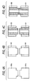
- Figs. 4A to 4D are explanatory drawings which show steps of connecting first and second planetary gears 100, 101 through welding.
- Gear wheel materials 100a, 101a each having a large diameter portion and a small diameter portion which continuously connects to the large diameter portion are molded by molds (Fig. 4A), teeth are cut into the large diameter portions of the gear wheel materials 100a, 101a by a hobbing machine (Fig.
- strain is generated in the connecting portion due to heat being applied to the planetary gears which is generated in association with welding, which causes a circumferential phase deviation between the first and second planetary gears, leading to a problem of increasing a difference between a backlash amount at a meshing portion between the first sun gear and the first planetary gear and a backlash amount at a meshing portion between the second sun gear and the second planetary gear.
- the small diameter portions of the first and second planetary gears need to be formed relatively long so as to secure a space necessary for welding, the overall length in the tooth face width direction of the planetary gear is increased, leading to a problem the variable angle ratio mechanism has to be made large in size.
- the invention was made in view of the situations, and a main object thereof is to provide a vehicle steering system which can decrease the number of machining steps of producing a planetary gear, eliminate the circumferential phase deviation in the planetary gears and decrease the overall length in the tooth face width direction of the same.
- a vehicle steering system including a variable angle ratio mechanism for changing an angle ratio of a steering angle of a steering member to a turning angle of a steering mechanism, the variable angle ratio mechanism including, in turn, a first sun gear connected to the steering member, a second sun gear connected to the steering mechanism, and planetary gears each having a first toothed portion and a second toothed portion which are adapted to mesh with the first and second sun gears, respectively, and are arranged to be spaced apart from each other in a tooth face width direction, the first toothed portion and the second toothed portion being formed integrally through forging.
- a vehicle steering system according to the first aspect of the invention, wherein the first toothed portion and the second toothed portion are formed from respective end edges in the tooth face width direction towards a center of the planetary gear.
- the first toothed portion and the second toothed portion of the planetary gear are formed integrally through forging, the number of machining steps of the planetary gear can be reduced, whereby the production costs of the planetary gears and hence the vehicle steering system can be reduced.
- the toothed portions are formed integrally through forging, the circumferential phase deviation between the first toothed portion and the second toothed portion can be eliminated, and the backlash amounts at the meshing portions with the first and second sun gears can be made even, thereby making it possible to reduce chattering due to backlash.
- a non-toothed portion between the first toothed portion and the second toothed portion can be reduced, and hence, the overall length in the tooth face width direction of the planetary gear can be made short, whereby the planetary gear and hence the vehicle steering system which incorporates therein the planetary gear can be made small in size.
- tooth surfaces of the first toothed portion and the second toothed portion can be pressure hardened, the heat treatment such as quenching can be omitted.
- the tooth surfaces so pressure hardened are made smoother than tooth surfaces which are formed by cutting, sliding noise can be reduced which is generated when tooth surfaces of the toothed portions are brought into sliding contact with each other.
- Fig. 1 is an exemplary diagram showing the configuration of a vehicle steering system according to the invention
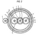
- Fig. 2 is a sectional view taken along the line II-II in Fig. 1.
- This vehicle steering system includes a steering column 1, to an upper end of which a steering wheel (the steering member) is connected, and a variable angle ratio mechanism A, which is provided between an upper end of a transmission shaft or pinion shaft 3 of a steering mechanism 2 which includes a pinion 21 connected to the other end of the pinion shaft 3 and a turning shaft or rack shaft 22 having rack teeth 22a adapted to mesh with the pinion 21 and adapted to move in axially longitudinal directions and a lower end of the steering column 1 for changing an angle ratio of a steering angle of the steering column 1 to a turning angle of the steering mechanism 2, whereby steered road wheels B, B which are supported on both end portions of the rack shaft 22, respectively, can be steered as a result of turning of the steering column 1.
- the variable angle ratio mechanism A includes a first sun gear 4 which is provided at the lower end of the steering column 1, a second sun gear 5 which is disposed coaxially with the first sun gear 4 and is provided at the upper end of the pinion shaft 3, a plurality of planetary gears 6 each having a first toothed portion 61 adapted to mesh with the first sun gear 4 and a second toothed portion 62 adapted to mesh with the second sun gear 5, a carrier 7 which supports the planetary gears 6 in such a manner as to freely rotate about their own axes and revolve around the sun gears, an externally toothed element 8 which is provided on an outer circumferential portion of the carrier 7, and an electric motor 10 having a first drive gear 9 which meshes with the externally toothed element 8 and functioning as a differential actuator for rotating the carrier 7.
- the vehicle steering system includes a transmission gear 11 provided in an intermediate position along the steering column 1 and an electric motor 13 having a second drive gear 12 which meshes with the transmission gear 11 and functioning as a torque varying actuator for changing torque applied to the steering column 1.
- the steering column 1 and the pinion shaft 3 are supported rotatably on a stationary member via bearings, and the first and second sun gears 4, 5 face coaxially the steering column 1 and the pinion shaft 3, respectively.
- a torque sensor (not shown) is provided on an outer periphery of the steering column 1 for detecting a torque applied to the steering column 1, and a control unit 14 is provided for controlling drive circuits 10a, 13a of the electric motors 10, 13 based on the torque detected by the torque sensor or the like.
- the first toothed portion 61 which constitutes a straight-tooth spur gear portion and the second toothed portion 62 which constitutes a straight-tooth spur gear portion are disposed in such a manner as to be spaced apart in the tooth face direction, the numbers of teeth of the first toothed portion 61 and the second toothed portion 62 differ from each other.
- This planetary gear 6 is cold forged by means of a first die C having a first forming portion which corresponds to the first toothed portion 61 and a second die D having a second forming portion which corresponds to the second toothed portion 62.
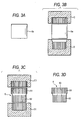
- Figs. 3A through 3D are explanatory diagrams showing a machining method.
- a gear wheel material 6a (Fig. 3A) that is formed by cutting a wire material to a predetermined length is disposed between a first performing die C and a second performing die D (Fig. 3B), and the second die D is moved vertically a plurality of times to beat the gear wheel material, so as to forge a first toothed portion 61 and a second toothed portion 62 at both end portions of the gear wheel material 6a.
- a finish forging is given to the first toothed portion 61 and the second toothed portion 62 by a first finishing die C1 and a second finishing case die D1, respectively (Fig.
- a shaft hole 63 is opened in a central portion of a resulting forged gear 6 by a boring machine (Fig. 3D).
- a draft angle is set on first forming portions of the first dies C, C1 and second forming portions of the second dies D, D1. Consequently, tooth surfaces, tooth tip surfaces and tooth root surfaces of the first toothed portion 61 and the second toothed portion 62 are slightly inclined relative to a center axis of the gear 6 as a result of the provision of the draft angle in such a way as to correspond thereto.
- the heat treatment of quenching may only have to be carried out as required and, hence, can be omitted.
- the carrier 7 has a first disc-shaped plate portion 7a which is rotatably fitted to be supported on an outer circumferential portion of the steering column 1 via a needle bearing, a second disc-shaped plate portion 7b which is rotatably fitted to be supported on an outer circumferential portion of the pinion shaft 3 via a needle bearing, and a cylindrical connecting portion 7c which connects together the first plate portion 7a and the second plate portion 7b by means of connecting means such as bolts, and the annular externally toothed element 8 having a plurality of teeth is provided integrally on an outer circumferential portion of the cylindrical connecting portion 7c.
- a first fitting hole 71 is provided in a rotational center portion of each of the first plate portion 7a and the second plate portion 7b, and two second fitting holes 72, 72 are also provided in each of the first and second plate portions in positions which are deflected from the rotational center portion and are located in such a manner as to divide the circumference of the plate portion into two equally. End portions of shaft elements 15 of the planetary gears 6 are fitted in the second fitting holes 72, 72 via needle bearings, respectively.
- the electric motor 10 for differential actuator is driven by a command signal that is outputted to the drive circuit 10a from the control unit 14, whereby the carrier 7 is rotated via the first drive gear 9 and the externally toothed element 8, the pinion shaft 3 is then rotated at increased speeds via the first toothed portions 61 and the second toothed portions 62 of the planetary gears 6 and the sun gear 5, and the angle ratio of the steering angle of the steering column 1 to the turning angle of the steering mechanism 2 is changed.
- the electric motor 13 for torque changing is driven by a command signal outputted to the drive circuit 13a from the control unit 14 according to the torque applied to the steering column 1 or the like, thereby making it possible to maintain the torque applied to the steering column 1 at the predetermined value.
- first toothed portion 61 and the second toothed portion 62 of the planetary gear 6 are formed integrally through cold forging, the number of machining steps of the planetary gear 6 can be decreased. Since the tooth surfaces of the first toothed portion 61 and the second toothed portion 62 which are formed through forging are pressure hardened, the heat treatment of quenching can be omitted.
- the length of the non-toothed portion between the first toothed portion 61 and the second toothed portion 62 can be made shorter than that of the conventional planetary gear in which the two gear wheels are welded together, whether a planetary gear is formed through forging or cutting can easily be determined by looking at the tooth surfaces and the non-toothed portion.
- the planetary gear 6 is described as having the first toothed portion 61 and the second toothed portion 62 whose teeth are straight, the first toothed portion 61 and the second toothed portion 62 may have helical teeth.
- a vehicle steering system which includes a variable angle ratio mechanism for changing an angle ratio of a steering angle of a steering member to a turning angle of a steering mechanism, the variable angle ratio mechanism including a first sun gear connected to a steering column, a second sun gear connected to the steering mechanism, and planetary gears each having a first toothed portion and a second toothed portion which are adapted to mesh with the first and second sun gears respectively, and are arranged to be spaced apart from each other in a tooth face width direction, the first toothed portion and the second toothed portion being formed integrally through forging.
Landscapes
- Engineering & Computer Science (AREA)
- Chemical & Material Sciences (AREA)
- Combustion & Propulsion (AREA)
- Transportation (AREA)
- Mechanical Engineering (AREA)
- Power Steering Mechanism (AREA)
- Retarders (AREA)
- Steering Controls (AREA)
Abstract
A vehicle steering system is provided which includes a variable angle ratio mechanism (A) for changing an angle ratio of a steering angle of a steering member to a turning angle of a steering mechanism (2), the variable angle ratio mechanism including a first sun gear (4) connected to a steering column, a second sun gear (5) connected to the steering mechanism, and planetary gears (6) each having a first toothed portion (61) and a second toothed portion (62) which are adapted to mesh with the first and second sun gears respectively, and are arranged to be spaced apart from each other in a tooth face width direction, the first toothed portion (61) and the second toothed portion (62) being formed integrally through forging.
Description
- The present invention relates to a vehicle steering system including a angle variable mechanism for changing an angle ratio of a steering angle of a steering member to a turning angle of a steering mechanism for turning left and right steered wheels.
- A variable angle ratio mechanism included in a vehicle steering system is made up of a first sun gear which is connected to a steering member such as a steering wheel, a second sun gear which is disposed coaxially with the first sun gear and is connected to a steering mechanism, a first planetary gear which meshes with the first sun gear, a second planetary gear which meshes with the second sun gear and rotates together with the first planetary gear, a carrier which supports the first and second planetary gears in such a manner as to freely rotate about their own axes and revolve around the sun gears, and an electric motor for rotating the carrier, and is configured to rotate the second sun gear via the first sun gear, the first planetary gear and the second planetary gear and also to rotate the second sun gear at increased speeds via the carrier by virtue of driving by the electric motor, so as to change the angle ratio of steering angle to turning angle (for example,
JP-A-2005-343205 - There is known a vehicle steering system which includes such a variable angle ratio mechanism in which one ends of the first and second planetary gears which are formed by cutting are butted against each other, and the butted portion is welded so as to integrally connect the first and second planetary gears together. Figs. 4A to 4D are explanatory drawings which show steps of connecting first and second
planetary gears Gear wheel materials gear wheel materials planetary gears planetary gears - In a variable angle ratio mechanism in which first and second planetary gears are connected together by a connecting shaft as done in
JP-A-2005-343205 - In addition, in a variable angle ratio mechanism in which two planetary gears are connected together through welding, since there are necessary the steps of molding two gear wheel materials, cutting teeth in the gear wheel materials, applying a heat treatment to the same, opening shaft holes therein, grinding them and welding together the resulting gear wheels, the number of machining steps is increased, leading to a problem that the production costs of planetary gears and hence a vehicle steering system are increased. In addition, strain is generated in the connecting portion due to heat being applied to the planetary gears which is generated in association with welding, which causes a circumferential phase deviation between the first and second planetary gears, leading to a problem of increasing a difference between a backlash amount at a meshing portion between the first sun gear and the first planetary gear and a backlash amount at a meshing portion between the second sun gear and the second planetary gear. In addition, since the small diameter portions of the first and second planetary gears need to be formed relatively long so as to secure a space necessary for welding, the overall length in the tooth face width direction of the planetary gear is increased, leading to a problem the variable angle ratio mechanism has to be made large in size.
- The invention was made in view of the situations, and a main object thereof is to provide a vehicle steering system which can decrease the number of machining steps of producing a planetary gear, eliminate the circumferential phase deviation in the planetary gears and decrease the overall length in the tooth face width direction of the same.
- According to a first aspect of the invention, there is provided a vehicle steering system including a variable angle ratio mechanism for changing an angle ratio of a steering angle of a steering member to a turning angle of a steering mechanism, the variable angle ratio mechanism including, in turn, a first sun gear connected to the steering member, a second sun gear connected to the steering mechanism, and planetary gears each having a first toothed portion and a second toothed portion which are adapted to mesh with the first and second sun gears, respectively, and are arranged to be spaced apart from each other in a tooth face width direction, the first toothed portion and the second toothed portion being formed integrally through forging.
- According to a second aspect of the invention, there is provided a vehicle steering system according to the first aspect of the invention, wherein the first toothed portion and the second toothed portion are formed from respective end edges in the tooth face width direction towards a center of the planetary gear.
- According to the first and second aspects of the invention, since the first toothed portion and the second toothed portion of the planetary gear are formed integrally through forging, the number of machining steps of the planetary gear can be reduced, whereby the production costs of the planetary gears and hence the vehicle steering system can be reduced. Moreover, since the toothed portions are formed integrally through forging, the circumferential phase deviation between the first toothed portion and the second toothed portion can be eliminated, and the backlash amounts at the meshing portions with the first and second sun gears can be made even, thereby making it possible to reduce chattering due to backlash. In addition, since a non-toothed portion between the first toothed portion and the second toothed portion can be reduced, and hence, the overall length in the tooth face width direction of the planetary gear can be made short, whereby the planetary gear and hence the vehicle steering system which incorporates therein the planetary gear can be made small in size. Additionally, since tooth surfaces of the first toothed portion and the second toothed portion can be pressure hardened, the heat treatment such as quenching can be omitted. Furthermore, since the tooth surfaces so pressure hardened are made smoother than tooth surfaces which are formed by cutting, sliding noise can be reduced which is generated when tooth surfaces of the toothed portions are brought into sliding contact with each other.
-
- Fig. 1 is an exemplary diagram showing the configuration of a vehicle steering system according to the invention.
- Fig. 2 is a sectional view taken along the line II-II in Fig. 1.
- Figs. 3A through 3D are explanatory diagrams showing a machining method of a planetary gear for the vehicle steering system according to the invention.
- Figs. 4A through 4D are explanatory diagrams illustrating steps of connecting through welding planetary gear wheels for a conventional vehicle steering system.
- Hereinafter, an embodiment of the invention will be described in detail based on the drawings. Fig. 1 is an exemplary diagram showing the configuration of a vehicle steering system according to the invention, and Fig. 2 is a sectional view taken along the line II-II in Fig. 1.
- This vehicle steering system includes a
steering column 1, to an upper end of which a steering wheel (the steering member) is connected, and a variable angle ratio mechanism A, which is provided between an upper end of a transmission shaft or pinion shaft 3 of a steering mechanism 2 which includes apinion 21 connected to the other end of the pinion shaft 3 and a turning shaft orrack shaft 22 havingrack teeth 22a adapted to mesh with thepinion 21 and adapted to move in axially longitudinal directions and a lower end of thesteering column 1 for changing an angle ratio of a steering angle of thesteering column 1 to a turning angle of the steering mechanism 2, whereby steered road wheels B, B which are supported on both end portions of therack shaft 22, respectively, can be steered as a result of turning of thesteering column 1. - The variable angle ratio mechanism A includes a
first sun gear 4 which is provided at the lower end of thesteering column 1, asecond sun gear 5 which is disposed coaxially with thefirst sun gear 4 and is provided at the upper end of the pinion shaft 3, a plurality ofplanetary gears 6 each having a firsttoothed portion 61 adapted to mesh with thefirst sun gear 4 and a secondtoothed portion 62 adapted to mesh with thesecond sun gear 5, acarrier 7 which supports theplanetary gears 6 in such a manner as to freely rotate about their own axes and revolve around the sun gears, an externallytoothed element 8 which is provided on an outer circumferential portion of thecarrier 7, and anelectric motor 10 having afirst drive gear 9 which meshes with the externallytoothed element 8 and functioning as a differential actuator for rotating thecarrier 7. - In addition, the vehicle steering system includes a
transmission gear 11 provided in an intermediate position along thesteering column 1 and anelectric motor 13 having asecond drive gear 12 which meshes with thetransmission gear 11 and functioning as a torque varying actuator for changing torque applied to thesteering column 1. - The
steering column 1 and the pinion shaft 3 are supported rotatably on a stationary member via bearings, and the first andsecond sun gears steering column 1 and the pinion shaft 3, respectively. A torque sensor (not shown) is provided on an outer periphery of thesteering column 1 for detecting a torque applied to thesteering column 1, and acontrol unit 14 is provided for controllingdrive circuits electric motors - In the
planetary gear 6, the firsttoothed portion 61 which constitutes a straight-tooth spur gear portion and the secondtoothed portion 62 which constitutes a straight-tooth spur gear portion are disposed in such a manner as to be spaced apart in the tooth face direction, the numbers of teeth of the firsttoothed portion 61 and the secondtoothed portion 62 differ from each other. Thisplanetary gear 6 is cold forged by means of a first die C having a first forming portion which corresponds to the firsttoothed portion 61 and a second die D having a second forming portion which corresponds to thesecond toothed portion 62. - Figs. 3A through 3D are explanatory diagrams showing a machining method. In cold forging a
planetary gear 6, agear wheel material 6a (Fig. 3A) that is formed by cutting a wire material to a predetermined length is disposed between a first performing die C and a second performing die D (Fig. 3B), and the second die D is moved vertically a plurality of times to beat the gear wheel material, so as to forge a firsttoothed portion 61 and asecond toothed portion 62 at both end portions of thegear wheel material 6a. Thereafter, a finish forging is given to thefirst toothed portion 61 and thesecond toothed portion 62 by a first finishing die C1 and a second finishing case die D1, respectively (Fig. 3C) . After a heat treatment such as quenching is given to thegear wheel material 6a so finished, ashaft hole 63 is opened in a central portion of a resulting forgedgear 6 by a boring machine (Fig. 3D). A draft angle is set on first forming portions of the first dies C, C1 and second forming portions of the second dies D, D1. Consequently, tooth surfaces, tooth tip surfaces and tooth root surfaces of thefirst toothed portion 61 and thesecond toothed portion 62 are slightly inclined relative to a center axis of thegear 6 as a result of the provision of the draft angle in such a way as to correspond thereto. - In addition, the heat treatment of quenching may only have to be carried out as required and, hence, can be omitted.
- The
carrier 7 has a first disc-shaped plate portion 7a which is rotatably fitted to be supported on an outer circumferential portion of thesteering column 1 via a needle bearing, a second disc-shaped plate portion 7b which is rotatably fitted to be supported on an outer circumferential portion of the pinion shaft 3 via a needle bearing, and a cylindrical connectingportion 7c which connects together thefirst plate portion 7a and thesecond plate portion 7b by means of connecting means such as bolts, and the annular externallytoothed element 8 having a plurality of teeth is provided integrally on an outer circumferential portion of the cylindrical connectingportion 7c. - A
first fitting hole 71 is provided in a rotational center portion of each of thefirst plate portion 7a and thesecond plate portion 7b, and twosecond fitting holes shaft elements 15 of theplanetary gears 6 are fitted in thesecond fitting holes - In the vehicle steering system configured as has been described heretofore, when the
steering column 1 is operated to be turned by the steering wheel, the pinion shaft 3 is rotated via thefirst sun gear 4, the firsttoothed portions 61 and the secondtoothed portions 62 of theplanetary gears 6, and thesecond sun gear 5. In addition, theelectric motor 10 for differential actuator is driven by a command signal that is outputted to thedrive circuit 10a from thecontrol unit 14, whereby thecarrier 7 is rotated via thefirst drive gear 9 and the externallytoothed element 8, the pinion shaft 3 is then rotated at increased speeds via the firsttoothed portions 61 and the secondtoothed portions 62 of theplanetary gears 6 and thesun gear 5, and the angle ratio of the steering angle of thesteering column 1 to the turning angle of the steering mechanism 2 is changed. - When a torque being applied to the steering column is changed from a predetermined value due to the pinion shaft 3 being rotated at increased speeds, the
electric motor 13 for torque changing is driven by a command signal outputted to thedrive circuit 13a from thecontrol unit 14 according to the torque applied to thesteering column 1 or the like, thereby making it possible to maintain the torque applied to thesteering column 1 at the predetermined value. - In addition, since the
first toothed portion 61 and the secondtoothed portion 62 of theplanetary gear 6 are formed integrally through cold forging, the number of machining steps of theplanetary gear 6 can be decreased. Since the tooth surfaces of the firsttoothed portion 61 and the secondtoothed portion 62 which are formed through forging are pressure hardened, the heat treatment of quenching can be omitted. In addition, since the pressure hardened tooth surfaces are made smooth and moreover, the length of the non-toothed portion between the firsttoothed portion 61 and the secondtoothed portion 62 can be made shorter than that of the conventional planetary gear in which the two gear wheels are welded together, whether a planetary gear is formed through forging or cutting can easily be determined by looking at the tooth surfaces and the non-toothed portion. - Note that while in the embodiment that has been described heretofore, the
planetary gear 6 is described as having the firsttoothed portion 61 and the secondtoothed portion 62 whose teeth are straight, the firsttoothed portion 61 and the secondtoothed portion 62 may have helical teeth. - The present application is based on
Japanese Patent Application No. 2006-196146 filed on July 18, 2007 - A vehicle steering system is provided which includes a variable angle ratio mechanism for changing an angle ratio of a steering angle of a steering member to a turning angle of a steering mechanism, the variable angle ratio mechanism including a first sun gear connected to a steering column, a second sun gear connected to the steering mechanism, and planetary gears each having a first toothed portion and a second toothed portion which are adapted to mesh with the first and second sun gears respectively, and are arranged to be spaced apart from each other in a tooth face width direction, the first toothed portion and the second toothed portion being formed integrally through forging.
Claims (2)
- A vehicle steering system comprising:a variable angle ratio mechanism for changing an angle ratio of a steering angle of a steering member to a turning angle of a steering mechanism, the variable angle ratio mechanism comprising:a first sun gear connected to the steering member;a second sun gear connected to the steering mechanism; andplanetary gears each having a first toothed portion anda second toothed portion which are adapted to mesh with the first and second sun gears, respectively, and are arranged to be spaced apart from each other in a tooth face width direction, the first toothed portion and the second toothed portion being formed integrally through forging.
- A vehicle steering system according to Claim 1, wherein the first toothed portion and the second toothed portion are formed from respective end edges in the tooth face width direction towards a center of the planetary gear.
Applications Claiming Priority (1)
| Application Number | Priority Date | Filing Date | Title |
|---|---|---|---|
| JP2006196146A JP2008024059A (en) | 2006-07-18 | 2006-07-18 | Vehicle steering system |
Publications (1)
| Publication Number | Publication Date |
|---|---|
| EP1880918A2 true EP1880918A2 (en) | 2008-01-23 |
Family
ID=38669366
Family Applications (1)
| Application Number | Title | Priority Date | Filing Date |
|---|---|---|---|
| EP07111847A Withdrawn EP1880918A2 (en) | 2006-07-18 | 2007-07-05 | Variable steering angle ratio mechanism for a vehicle steering system |
Country Status (4)
| Country | Link |
|---|---|
| US (1) | US7665572B2 (en) |
| EP (1) | EP1880918A2 (en) |
| JP (1) | JP2008024059A (en) |
| CN (1) | CN101108629A (en) |
Families Citing this family (19)
| Publication number | Priority date | Publication date | Assignee | Title |
|---|---|---|---|---|
| IT1392732B1 (en) * | 2009-01-27 | 2012-03-16 | Palmarix Ltd | SYSTEM FOR CONTROL OF THE DRIVING OF A VEHICLE. |
| DE102009011352B3 (en) * | 2009-03-05 | 2010-07-15 | Bourns, Inc., Riverside | Torsion angle sensor for measuring torsion angle of two shafts coupled with each other, has torsion bar, by which two shafts are connected with each other, housing and rotational position sensor |
| DE102009029532B8 (en) * | 2009-04-27 | 2016-09-01 | Ford Global Technologies, Llc | Steering valve with planetary gear |
| JP4955737B2 (en) * | 2009-07-14 | 2012-06-20 | 株式会社日本自動車部品総合研究所 | Steering control device |
| US8833508B2 (en) * | 2009-12-23 | 2014-09-16 | Automotive Research & Testing Center | Electrical auxiliary module for a vehicle steering system |
| JP2012086633A (en) * | 2010-10-18 | 2012-05-10 | Ntn Corp | Power-assisted bicycle |
| CN103832467B (en) * | 2012-11-26 | 2016-05-18 | 上海汽车集团股份有限公司 | Compact electric power-assisted steering tubular column, pipe column type electric power steering gear and automobile |
| CN103253297B (en) * | 2013-05-29 | 2015-11-18 | 长城汽车股份有限公司 | For vehicle steering swivel system and there is the vehicle of this steering swivel system |
| JP2016159895A (en) * | 2015-03-05 | 2016-09-05 | 株式会社ショーワ | Reaction force actuator and steering device |
| KR101637819B1 (en) * | 2015-03-20 | 2016-07-07 | 현대자동차주식회사 | Afs system for vehicle |
| US10589774B2 (en) | 2015-05-01 | 2020-03-17 | Steering Solutions Ip Holding Corporation | Counter rotation steering wheel |
| US20160375931A1 (en) | 2015-06-25 | 2016-12-29 | Steering Solutions Ip Holding Corporation | Rotation control system for a steering wheel and method |
| US9845106B2 (en) * | 2015-08-31 | 2017-12-19 | Steering Solutions Ip Holding Corporation | Overload protection for belt drive mechanism |
| US10160472B2 (en) | 2015-10-20 | 2018-12-25 | Steering Solutions Ip Holding Corporation | Steering column with stationary hub |
| KR101806682B1 (en) * | 2016-04-12 | 2017-12-07 | 현대자동차주식회사 | Adaptive Front Steering system for vehicle |
| US10160473B2 (en) | 2016-09-13 | 2018-12-25 | Steering Solutions Ip Holding Corporation | Steering column decoupling system |
| KR102657328B1 (en) * | 2016-11-23 | 2024-04-15 | 현대자동차주식회사 | Steering apparatus for steer by wire system |
| US11459014B2 (en) * | 2017-11-10 | 2022-10-04 | Same Deutz-Fahr Italia S.P.A. | Adjustment assembly of a hydraulic steering system of a vehicle |
| KR102642206B1 (en) * | 2018-09-12 | 2024-03-04 | 엘지이노텍 주식회사 | Motor |
Family Cites Families (6)
| Publication number | Priority date | Publication date | Assignee | Title |
|---|---|---|---|---|
| JPH02190643A (en) * | 1989-01-13 | 1990-07-26 | Daishowa Seiki Co Ltd | Transmission gear |
| DE10160717A1 (en) * | 2001-12-11 | 2003-06-18 | Mercedes Benz Lenkungen Gmbh | Steering for motor vehicle with planetary gearbox and drive for superimposing torque on steering wheel has drive for applying torque directly to steering column |
| JP4147836B2 (en) * | 2002-06-21 | 2008-09-10 | 株式会社ジェイテクト | Vehicle steering system |
| DE10300641A1 (en) * | 2003-01-09 | 2004-07-22 | Siemens Ag | Servomotor drive e.g. for actuating motor vehicle parking brake, has first and second toothed wheels engaging with first and second toothed rings respectively, having non-identical number of teeth |
| US7244214B2 (en) * | 2004-02-03 | 2007-07-17 | Nissan Motor Co., Ltd. | Speed change device and steering system |
| JP4484038B2 (en) | 2004-05-31 | 2010-06-16 | 株式会社ジェイテクト | Vehicle steering system |
-
2006
- 2006-07-18 JP JP2006196146A patent/JP2008024059A/en active Pending
-
2007
- 2007-07-02 US US11/772,430 patent/US7665572B2/en not_active Expired - Fee Related
- 2007-07-05 EP EP07111847A patent/EP1880918A2/en not_active Withdrawn
- 2007-07-16 CN CNA2007101358324A patent/CN101108629A/en active Pending
Also Published As
| Publication number | Publication date |
|---|---|
| JP2008024059A (en) | 2008-02-07 |
| CN101108629A (en) | 2008-01-23 |
| US7665572B2 (en) | 2010-02-23 |
| US20080017435A1 (en) | 2008-01-24 |
Similar Documents
| Publication | Publication Date | Title |
|---|---|---|
| US7665572B2 (en) | Vehicle steering system | |
| DE102010017540B4 (en) | Steering control system | |
| US7669691B2 (en) | Steering device for vehicle | |
| EP1207095B1 (en) | Electric power steering apparatus and method of manufacturing gear used therefor | |
| US4624283A (en) | Rotary control valve of power steering system and method of producing spool valve member | |
| EP2937265A1 (en) | Rack shaft and method for manufacturing rack shaft | |
| EP2943390B1 (en) | Angle superimposition apparatus for a vehicle steering device | |
| EP3271614B1 (en) | Strain wave gear requiring reduced radial installation space | |
| US20090000120A1 (en) | Worm gear unit and method of producing same | |
| DE3830654A1 (en) | Differential-action steering system | |
| EP3643582B1 (en) | Shaft for steering device, method for manufacturing shaft for steering device, and electric power steering device | |
| JP2009041674A (en) | Gear member, gear mechanism, and manufacturing method of gear member | |
| US20080022798A1 (en) | Running Gear And Production Method | |
| JP4134701B2 (en) | Electric power steering device | |
| EP2090495A1 (en) | Vehicle steering device | |
| DE102011051531A1 (en) | Steering system for commercial vehicle, has steering gear and electric drive motor for generating driving torque and servo gear to step down driving torque | |
| WO2018193919A1 (en) | Rack shaft and method for manufacturing rack shaft | |
| JP4361350B2 (en) | Vehicle gear mechanism | |
| EP3072785B1 (en) | Steering column assist system | |
| KR102537011B1 (en) | Electric power steering apparatus | |
| JP2024045301A (en) | Steering Assistance Device | |
| JPH11124045A (en) | Electric power steering device | |
| JP2008215558A (en) | Worm gear device and worm wheel manufacturing method | |
| JP2010188821A (en) | Steering device for vehicle | |
| EP1431161B1 (en) | Steering system for a vehicle |
Legal Events
| Date | Code | Title | Description |
|---|---|---|---|
| PUAI | Public reference made under article 153(3) epc to a published international application that has entered the european phase |
Free format text: ORIGINAL CODE: 0009012 |
|
| AK | Designated contracting states |
Kind code of ref document: A2 Designated state(s): AT BE BG CH CY CZ DE DK EE ES FI FR GB GR HU IE IS IT LI LT LU LV MC MT NL PL PT RO SE SI SK TR |
|
| AX | Request for extension of the european patent |
Extension state: AL BA HR MK YU |
|
| STAA | Information on the status of an ep patent application or granted ep patent |
Free format text: STATUS: THE APPLICATION HAS BEEN WITHDRAWN |
|
| 18W | Application withdrawn |
Effective date: 20101111 |